EP1533671B1 - Appareil pour corriger une position apprise - Google Patents
Appareil pour corriger une position apprise Download PDFInfo
- Publication number
- EP1533671B1 EP1533671B1 EP04027316A EP04027316A EP1533671B1 EP 1533671 B1 EP1533671 B1 EP 1533671B1 EP 04027316 A EP04027316 A EP 04027316A EP 04027316 A EP04027316 A EP 04027316A EP 1533671 B1 EP1533671 B1 EP 1533671B1
- Authority
- EP
- European Patent Office
- Prior art keywords
- robot
- vision sensor
- mechanical unit
- teaching
- correcting device
- Prior art date
- Legal status (The legal status is an assumption and is not a legal conclusion. Google has not performed a legal analysis and makes no representation as to the accuracy of the status listed.)
- Active
Links
- 230000004438 eyesight Effects 0.000 claims description 88
- 238000012545 processing Methods 0.000 claims description 28
- 230000008859 change Effects 0.000 claims description 16
- 238000003860 storage Methods 0.000 claims description 10
- 238000003384 imaging method Methods 0.000 claims description 7
- 239000012636 effector Substances 0.000 claims description 6
- 238000000034 method Methods 0.000 description 20
- 238000004891 communication Methods 0.000 description 9
- 238000010586 diagram Methods 0.000 description 9
- 238000012937 correction Methods 0.000 description 7
- 238000003466 welding Methods 0.000 description 7
- 239000011159 matrix material Substances 0.000 description 6
- 238000005259 measurement Methods 0.000 description 6
- 230000000007 visual effect Effects 0.000 description 6
- 238000004519 manufacturing process Methods 0.000 description 5
- 230000008901 benefit Effects 0.000 description 4
- 230000006870 function Effects 0.000 description 4
- 238000006243 chemical reaction Methods 0.000 description 3
- 230000007246 mechanism Effects 0.000 description 3
- 230000008569 process Effects 0.000 description 3
- 238000004364 calculation method Methods 0.000 description 2
- 239000002184 metal Substances 0.000 description 2
- 238000010521 absorption reaction Methods 0.000 description 1
- 238000004458 analytical method Methods 0.000 description 1
- 238000012790 confirmation Methods 0.000 description 1
- 230000007423 decrease Effects 0.000 description 1
- 230000003247 decreasing effect Effects 0.000 description 1
- 230000000694 effects Effects 0.000 description 1
- 239000004973 liquid crystal related substance Substances 0.000 description 1
- 238000012986 modification Methods 0.000 description 1
- 230000004048 modification Effects 0.000 description 1
- 230000002093 peripheral effect Effects 0.000 description 1
- 238000002360 preparation method Methods 0.000 description 1
- 238000007634 remodeling Methods 0.000 description 1
- 230000009466 transformation Effects 0.000 description 1
Images


Classifications
-
- G—PHYSICS
- G05—CONTROLLING; REGULATING
- G05B—CONTROL OR REGULATING SYSTEMS IN GENERAL; FUNCTIONAL ELEMENTS OF SUCH SYSTEMS; MONITORING OR TESTING ARRANGEMENTS FOR SUCH SYSTEMS OR ELEMENTS
- G05B19/00—Programme-control systems
- G05B19/02—Programme-control systems electric
- G05B19/18—Numerical control [NC], i.e. automatically operating machines, in particular machine tools, e.g. in a manufacturing environment, so as to execute positioning, movement or co-ordinated operations by means of programme data in numerical form
- G05B19/408—Numerical control [NC], i.e. automatically operating machines, in particular machine tools, e.g. in a manufacturing environment, so as to execute positioning, movement or co-ordinated operations by means of programme data in numerical form characterised by data handling or data format, e.g. reading, buffering or conversion of data
- G05B19/4083—Adapting programme, configuration
-
- B—PERFORMING OPERATIONS; TRANSPORTING
- B25—HAND TOOLS; PORTABLE POWER-DRIVEN TOOLS; MANIPULATORS
- B25J—MANIPULATORS; CHAMBERS PROVIDED WITH MANIPULATION DEVICES
- B25J9/00—Programme-controlled manipulators
- B25J9/16—Programme controls
- B25J9/1679—Programme controls characterised by the tasks executed
- B25J9/1692—Calibration of manipulator
-
- G—PHYSICS
- G05—CONTROLLING; REGULATING
- G05B—CONTROL OR REGULATING SYSTEMS IN GENERAL; FUNCTIONAL ELEMENTS OF SUCH SYSTEMS; MONITORING OR TESTING ARRANGEMENTS FOR SUCH SYSTEMS OR ELEMENTS
- G05B2219/00—Program-control systems
- G05B2219/30—Nc systems
- G05B2219/36—Nc in input of data, input key till input tape
- G05B2219/36504—Adapt program to real coordinates, shape, dimension of tool, offset path
-
- G—PHYSICS
- G05—CONTROLLING; REGULATING
- G05B—CONTROL OR REGULATING SYSTEMS IN GENERAL; FUNCTIONAL ELEMENTS OF SUCH SYSTEMS; MONITORING OR TESTING ARRANGEMENTS FOR SUCH SYSTEMS OR ELEMENTS
- G05B2219/00—Program-control systems
- G05B2219/30—Nc systems
- G05B2219/37—Measurements
- G05B2219/37555—Camera detects orientation, position workpiece, points of workpiece
-
- G—PHYSICS
- G05—CONTROLLING; REGULATING
- G05B—CONTROL OR REGULATING SYSTEMS IN GENERAL; FUNCTIONAL ELEMENTS OF SUCH SYSTEMS; MONITORING OR TESTING ARRANGEMENTS FOR SUCH SYSTEMS OR ELEMENTS
- G05B2219/00—Program-control systems
- G05B2219/30—Nc systems
- G05B2219/39—Robotics, robotics to robotics hand
- G05B2219/39024—Calibration of manipulator
-
- G—PHYSICS
- G05—CONTROLLING; REGULATING
- G05B—CONTROL OR REGULATING SYSTEMS IN GENERAL; FUNCTIONAL ELEMENTS OF SUCH SYSTEMS; MONITORING OR TESTING ARRANGEMENTS FOR SUCH SYSTEMS OR ELEMENTS
- G05B2219/00—Program-control systems
- G05B2219/30—Nc systems
- G05B2219/39—Robotics, robotics to robotics hand
- G05B2219/39057—Hand eye calibration, eye, camera on hand, end effector
Definitions
- the present invention relates to a teaching position correcting device for a robot.
- the invention relates to a teaching position correcting device that is used to correct a teaching position of a motion program for a robot when at least one of the robot and an object to be worked is moved.
- the above method of changing the robot program according touchup is based on positional data of the workpiece or the holder obtained by measuring their positions before and after the move using the touchup of the robot.
- the finally obtained program cannot easily achieve high-precision work because of presence of both or one of a setting error of the TCP of the robot and a positioning error of the touchup to the reference points.
- the robot is manually operated by jog feed or the like, and the TCP of the robot is matched with a target point.
- the TCP setting and the positioning have different precision levels depending on the orientation of the robot when TCP setting and positioning are carried out or depending on operator's skill.
- positioning is carried out based on visual measurement, even a skilled operator cannot achieve high-precision work. Therefore, it becomes essential to correct each teaching position after the shifting.
- the present invention has been made to solve the above problems, and has an object of providing a device that can easily correct in high precision teaching positions after a shifting and can reduce load on an operator who corrects the teaching associated with the shifting.
- a teaching position correcting device that corrects a teaching position of a motion program for a robot equipped with a robot mechanical unit.
- the teaching position correcting device includes: a storage that stores the teaching position of the motion program; a vision sensor that is provided at a predetermined part of the robot mechanical unit, and measures a position and orientation of the vision sensor relative to the predetermined part and a three-dimensional position of each of at least three sites not aligned in a straight line on an object to be worked by the robot; a position calculator that obtains a three-dimensional position of each of the at least three sites before and after a change respectively of a position of the robot mechanical unit relative to the object to be worked, based on measured data obtained by the vision sensor; and a robot control device that corrects the teaching position of the motion program stored in the storage, based on a change in the relative position obtained by the position calculator.
- the robot mechanical unit has an end effector that works the object, and the vision sensor can be attached to the end effector.
- the teaching position correcting device includes: a storage that stores the teaching position of the motion program; a vision sensor that is provided at a predetermined part of other than the robot mechanical unit, and measures a three-dimensional position of each of at least three sites not aligned in a straight line on an object to be worked by the robot and a three-dimensional position of each of at least three sites not aligned in a straight line on the robot mechanical unit; a position calculator that obtains a three-dimensional position of each of the at least three sites of the object to be worked and a three-dimensional position of each of the at least three sites of the robot mechanical unit before and after a change respectively of a position of the robot mechanical unit relative to the object to be worked, based on measured data obtained by the vision sensor; and a robot control device that corrects the teaching position of the motion program stored in the storage, based on a change
- the vision sensor is attached to another robot mechanical unit of a second robot different from the above robot.
- the vision sensor is detachably attached to the robot mechanical unit, and can be detached from the robot mechanical unit when the vision sensor stops measuring of the three-dimensional positions of the at least three sites of the object.
- a position and orientation of the vision sensor relative to the robot mechanical unit can be obtained by measuring a reference object at a predetermined position from plural different points, each time when the vision sensor is attached to the robot mechanical unit.
- the at least three sites of the object can be shape characteristics that the object has.
- the at least three sites of the object can be reference marks formed on the object.
- the vision sensor can have a camera that carries out an image processing, and the camera can obtain a three-dimensional position of a measured site by imaging the measured part at plural different positions.
- This camera can be an industrial television camera, for example.
- the vision sensor can be a three-dimensional vision sensor.
- the three-dimensional vision sensor can be a combination of an industrial television camera and a projector.
- the vision sensor mounted on the robot mechanical unit measures three-dimensional positions of plural specific sites on the object to be worked. Based on three-dimensional positions measured before and after the shifting respectively, a coordinate conversion necessary to correct the teaching position is obtained. By working the coordinate conversion on the teaching position data of the motion program, the teaching position of the program is corrected.
- the teaching position correcting device is designed to correct a teaching position of a motion program for a robot when at least one of the robot having a robot mechanical unit and an object to be worked by the robot is moved.
- the teaching position correcting device has: a storage that stores the teaching position of the motion program; a vision sensor that is configured to measure a three-dimensional position of each of at least three sites not aligned in a straight line on the object to be worked by the robot; a position calculator that obtains a three-dimensional position of each of the at least three sites before and after a change respectively of a position of the robot mechanical unit relative to the object to be worked, based on measured data obtained by the vision sensor; and a robot control device that corrects the teaching position of the motion program stored in the storage, based on a change in the relative position obtained by the position calculator.
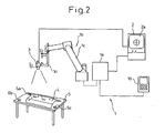
- Fig. 2 is a total configuration diagram of a robot system according to an embodiment of the present invention.
- a reference numeral 1 denotes a known representative robot.
- the robot 1 has a robot control device 1a having a system configuration shown in Fig. 3 , and a robot mechanical unit 1b of which operation is controlled by the robot control device 1a.
- the robot control device 1a has a main CPU (a main central processing unit; hereinafter, simply referred to as a CPU) 11, a bus 17 that is connected to the CPU 11, a storage or a memory 12 connected to the bus 17 consisting of a RAM (random access memory), a ROM (read-only memory) and a non-volatile memory, a teaching board interface 13, an input/output interface 16 for external units, a servo control 15, and a communication interface 14.
- a main CPU a main central processing unit; hereinafter, simply referred to as a CPU
- a bus 17 that is connected to the CPU 11
- a storage or a memory 12 connected to the bus 17 consisting of a RAM (random access memory), a ROM (read-only memory) and a non-volatile memory
- teaching board interface 13 an input/output interface 16 for external units
- a servo control 15 a communication interface 14.
- a teaching board 18 that is connected to the teaching board interface 13 can have a usual display function.
- An operator prepares, corrects, and registers a motion program for a robot by manually operating the teaching board 18.
- the operator also sets various parameters, operates the robot based on the taught motion program, jog feeds, in the manual mode.
- a system program that supports the basic function of the robot and the robot control device is stored in the ROM of the memory 12.
- the motion program (in this case, a spot welding) of the robot taught according to the application and relevant set data are stored in the non-volatile memory of the memory 12.
- a program and parameters used to carry out the processing relevant to the correction of the teaching position data to be described later are also stored in the non-volatile memory of the memory 12.
- the RAM of the memory 12 is used for a storage area to temporarily store various data processed by the CPU 11.
- the servo control 15 has servo controllers #1 to #n, where n is a total number of axes of the robot, and n is assumed to be equal to 6 in this case.
- the servo control 15 receives a shift command prepared through operations (such as a path plan preparation, and interpolation and an inverse transformation based on the plan) to control the robot.
- the servo control 15 outputs torque commands to servo amplifiers A1 to An based on the shift command and feedback signals received from pulse coders not shown belonging to the axes.
- the servo amplifiers A1 to An supply currents to servomotors of the respective axes based on the torque commands, thereby driving the servomotors.
- the communication interface 14 is connected to the position calculator, that is, an image processing unit 2 shown in Fig. 2 .
- the robot control device 1a exchanges commands relevant to measurement and measured data described later with the image processing unit 2 via the communication interface 14.
- the image processing unit 2 has a block configuration as shown in Fig. 4 .
- the image processing unit 2 has a CPU 20 including microprocessors, and also has a ROM 21, an image processor 22, a camera interface 23, a monitor interface 24, an input/output (I/O) unit 25, a frame memory (i.e., an image memory) 26, a non-volatile memory 27, a RAM 28, and a communication interface 29, that are connected to the CPU 20 via a bus line 30, respectively.
- a CPU 20 including microprocessors, and also has a ROM 21, an image processor 22, a camera interface 23, a monitor interface 24, an input/output (I/O) unit 25, a frame memory (i.e., an image memory) 26, a non-volatile memory 27, a RAM 28, and a communication interface 29, that are connected to the CPU 20 via a bus line 30, respectively.
- I/O input/output
- a camera as an imaging unit of a vision sensor 3, that is, a CCD (charge-coupled device) camera in this case, is connected to the camera interface 23.
- the camera receives an imaging command via the camera interface 23
- the camera picks up an image using an electronic shutter function incorporated in the camera.
- the camera sends a picked-up video signal to the frame memory 26 via the camera interface 23, and the frame memory 26 stores the video signal in the form of a grayscale signal.
- a display such as a CRT (cathode ray tube) or an LCD (liquid crystal display) is connected to the monitor interface 24, as a monitor 2a (refer to Fig. 2 and Fig. 6 ).
- the monitor 2a displays images currently picked up by the camera, past images stored in the frame memory 26, or images processed by the image processor 22, according to need.
- the image processor 22 analyses the video signal of the workpiece stored in the frame memory 26.
- the image processor 22 recognizes selected reference marks 6a, 6b, and 6c, not aligned in a straight line, that indicate positions of three sites on a holder 5. Based on this recognition, a three-dimensional position of each of the marks 6a, 6b, and 6c is obtained, as described later in detail.
- a program and parameters for this purpose are stored in the non-volatile memory 27.
- the RAM 28 temporarily stores data that the CPU 20 uses to execute various processing.
- the communication interface 29 is connected to the robot control device via the communication interface 14 at the robot control device side.
- an end effector such as a work tool 1d (a welding gun for spot welding in the present example) is fitted to a front end of a robot arm 1c that the robot mechanical unit 1b of the robot 1 has.
- the robot 1 carries out a welding to a workpiece 4 (a sheet metal to be welded in the present example).
- the workpiece 4 is held on the holder 5.
- the workpiece 4 and the holder 5 keep a constant relative positional relationship between them. This relative relationship does not change after a shift to be described later.
- a representative holder 5 is a fixture having a clamp mechanism that fixes the sheet metal.
- the object to be worked (hereinafter simply referred to as an object) according to the present embodiment is the workpiece 4, or the workpiece 4 and the. holder 5 when the holder 5 is used.
- the motion program for the robot that carries out a welding is taught in advance, and is stored in the robot control device 1a.
- the vision sensor (i.e., a sensor head) 3 is connected to the image processing unit 2.
- the image processing unit 2 processes an image input from the vision sensor 3, and detects a specific point or a position of a shape characteristic within the sensor image.
- the vision sensor 3 is the CCD camera that picks up a two-dimensional image.
- the vision sensor 3 is detachably attached to a predetermined part such as the work tool 1d of the robot, with suitable fitting means, such as absorption utilizing a permanent magnet or clamping using a vise function, for example.
- the vision sensor 3 can be once detached from the work tool 1d after a measuring before the shifting described later, and mounted again after the shifting. Otherwise, the work tool 1d can be shifted in a state of being mounted with the vision sensor 3, when this has no problem. In the former case, one vision sensor can be used to correct teaching positions of plural robots.
- a relative relationship between a coordinate system ⁇ f of a mechanical interface on a final link of the robot 1 and a reference coordinate system ⁇ c of the vision sensor can be set in advance, or can be set by calibration when the vision sensor 3 is fitted to the work tool 1d.
- the vision sensor 3 is once detached after the measuring before the shifting, calibration is also carried out after the shifting.
- the vision sensor is calibrated according to a known technique, which is briefly explained later.
- the teaching position of the motion program for the welding robot can be completely corrected easily and accurately.
- a processing procedure described in a flowchart shown in Fig. 5 is executed.
- the processing at steps 100 to 105 concerns the measuring before the shifting.
- the measuring is prepared, and three-dimensional positions of the three reference marks formed on the holder 5 are measure, at these steps.
- the processing concerns the measuring after the shifting.
- the measuring is prepared, and three-dimensional positions of the three reference marks are measured, at steps 200 to 205.
- steps 300 to 302 a move distance of the holder from the robot is calculated based on the mark positions before and after the shifting, and the teaching position of the motion program for the robot, taught before the shifting, is corrected.
- parentheses [ ] are used as a symbol that represents a matrix.
- Step 100 The vision sensor (i.e., CCD camera) 3 is fitted to the work tool 1d.
- the vision sensor 3 has a sensor head equipped with a camera and a projector, this sensor head is fitted to the work tool 1d.
- the vision sensor 3 is detachably fitted, and is once detached later (refer to step 150).
- Step 101 A sensor fitting position and orientation is calibrated to obtain a relative position and orientation relationship between the coordinate system ⁇ f of a final link of the robot and the reference coordinate system ⁇ c of the fitted vision sensor (i.e., camera).
- a known calibration method can be suitably used.
- Fig. 6 shows an example of the disposition when one of the calibration methods is employed.
- a reference object R used for calibration which includes plural dots d arrayed in a known interval, is placed within a robot work area. This reference object R is the one that is generally used to calibrate the vision sensor.
- the operator shifts, in a manual mode like jog feed, the robot to a first position A1 where the reference object R is within the field of vision of the vision sensor.
- the operator operates the keyboard of the image processing unit, to instruct the input of an image for a first calibration.
- the image processing unit 2 picks up an image from the vision sensor.
- the image processing unit analyzes the reference object R for calibration, and obtains data of a position and orientation [D1] of the reference object R viewed from the sensor coordinate system ⁇ c, from the positions of the dots on the image, dot intervals, and a dot layout.
- the image processing unit fetches a position and orientation [A1] of the coordinate system ⁇ f of the final link at the imaging time, from the robot control device via the communication interface, and stores [D1] and [A1] into the memory of the image processing unit.
- the robot is moved to a separate position A2, and [D2] and [A2] are stored. Further, the robot is moved to a position A3 that is not aligned in a straight line connecting between A1 and A2, and [D3] and [A3] are stored. In general, [Di] and [Ai] are obtained at three or more different positions not aligned in a straight line.
- the image processing unit calculates a position and orientation [S] of the sensor coordinate system ⁇ c relative to the final link ⁇ f, from plural pairs of [Di] and [Ai] obtained in this way, and stores the calculates result [S].
- the relationship between the coordinate system ⁇ f of a final link and the reference coordinate system ⁇ c of the vision sensor is set by calibration.
- a camera fitting fixture is designed to be able to fit the vision sensor to the final link of the robot in the same position and orientation each time, calibration can be omitted and a relationship between ⁇ c and ⁇ f known in advance can be set to the image processing unit from the input unit like the keyboard.
- Steps 102, 103, 104 and 105 After ending the calibration, three-dimensional positions of the first to the third reference marks (refer to 6a to 6c in Fig. 2 ) formed on the holder 5 that holds the workpiece 4 are measured.
- the three reference marks are selected at positions not aligned in a straight line.
- Each of these reference marks is formed in a circle or a cross shape, and is prepared or posted to the workpiece or the holder, when the workpiece or the holder has no feature that the vision sensor can easily detect, such as a plane sheet.
- ready-made parts having a shape characteristic can be used. Holes and corners of which positions can be accurately obtained by image processing are preferable for these parts. There is no particular limit to the parts so long as they have a feature of which position the vision sensor can detect.
- a part of or the whole reference marks, or alternative shape characteristics or characteristic parts, may be provided on the workpiece 4.
- the operator operates the robot to move the robot to a position B1 at which the first reference mark 6a is in the vision field of the vision sensor.
- the operator instructs to input an image from the keyboard of the image processing unit.
- the image processing unit picks up the image from the sensor, and detects the position of the first reference mark 6a on the image.
- the image processing unit fetches a position [B1] of the final link ⁇ f at the imaging time, from the robot control device via the communication interface.
- the image processing unit picks up the image of the sensor based on the instruction from the operator, detects the position of the first reference mark 6a on the image, and fetches a robot position [B1'], in a similar manner to that of fetching the position at B1.
- the position of the sensor coordinate system ⁇ c at [B1] and [B1'] in the robot coordinate system is obtained from [B1], [B1'], and the position and orientation [S] of the sensor coordinate system ⁇ c relative to the final link ⁇ f obtained by the calibration.
- a three-dimensional position P1(x1, y1, z1) of the mark 6a in the robot coordinate system can be obtained, based on a known stereo view principle.
- the vision sensor is a three-dimensional vision sensor using a projector
- the position P1(x1, y1, z1) of each reference mark can be measured by imaging at one robot position.
- the obtained position P1(x1, y1, z1) is sent to the robot control device via the communication interface, and is stored in the memory within the robot control device.
- the resolution of a general vision sensor is from 1/500 to 1/1000 or above of the range of the field of vision. Therefore, the vision sensor can measure positions of the reference marks in substantially higher precision than that achieved by visual observation.
- the operator shifts the robot to positions where the second and third reference marks 6b and 6c are within the field of vision of the sensor respectively, measures three-dimensional positions P2(x2, y2, z2) and P3(x3, y3, z3) of the second and third marks respectively, and stores these three-dimensional positions in the memory within the robot control device.
- the operator can manually shift the robot by jog feed.
- a robot motion program to measure the mark measuring positions is prepared in advance, and each measuring position is taught to the motion program.
- the measured positions of the three reference marks can be stored in the memory of the image processing unit.
- Step 150 After the reference marks are measured before the shifting, the vision sensor can be detached or does not need to be detached from the work tool.
- the robot 1 and the holder 5 are shifted to separate positions, and are set up again.
- Steps 200 and 201 After the shifting, the vision sensor is fitted to the front end of the robot work tool again, and calibration is carried out again in the same process as that before the shifting. When the vision sensor is kept fitted to the front end of the robot work tool, these steps can be omitted.
- Steps 202, 203, 204 and 205 In the layout after the shifting, positions of the reference marks 6a, 6b and 6c on the holder are measured again in the same process as that before the shifting. Obtained mark positions after the shifting, P1'(x1', y1', z1'), P2'(x2', y2', z2') and P3'(x3', y3', z3') are stored.
- the reference mark positions before the shifting P1(x1, y1, z1), P2(x2, y2, z2) and P3(x3, y3, z3), and the reference mark positions after the shifting, P1'(x1', y1', z1'), P2'(x2', y2', z2') and P3'(x3', y3', z3'), for the three reference marks on the holder 5 are stored in the memory of the robot control device.
- the operator operates the robot teaching board 18 to instruct the motion program of which teaching positions should be corrected.
- the operator instructs the memory area in which the positions of the three reference marks before and after the shifting respectively are stored, and instructs to correct the teaching positions of the motion program.
- Step 300 The robot control device calculates a matrix [W1] that expresses the position and orientation of the holder before the shifting, from the reference mark positions P1, P2 and P3 before the shifting.
- Step 301 The robot control device calculates a matrix [W2] that expresses the position and orientation of the holder after the shifting, from the reference mark positions P1', P2' and P3' after the shifting.
- Step 302 Coordinate conversion is carried to each teaching position of the assigned motion program, using the above expression (2). As a result, the teaching position after correcting the relative positional deviation between the robot and the object due to the shifting can be obtained.
- a second robot 1' including another robot mechanical unit 1b' can be provided in addition to the robot 1 that carries out the work, as shown in Fig. 8 .
- the robot mechanical unit 1b' has the vision sensor 3 that measures three-dimensional positions of the reference marks 6a to 6c or alternative shape characteristics. In this case, it is necessary to obtain the position of the robot mechanical unit 1b that works the object, in addition to the position of the object.
- reference marks 7a to 7c are set to at least three sites (three sites in the example) that are not aligned in a straight line, on a robot base 8 of the robot mechanical unit 1b, and these position coordinates before and after the shifting can be measured using the vision sensor 3 mounted on the robot mechanical unit 1b', in a similar manner to that when the three reference marks 6a to 6c on the holder 5 are measured.
- the reference marks 7a to 7c on the robot mechanical unit 1b are set to sites that do not move when the orientation of the robot mechanical unit 1b changes, like the robot base 8.
- the robot mechanical unit 1b takes the same orientation at the measuring time before the shifting and at the measuring time after the shifting.
- the robot mechanical unit 1b takes a different orientation, it is necessary to obtain a change in the position of the robot after the shifting by taking the difference of orientations into consideration. This requires a complex calculation, and can easily generate error.
- a position of the robot mechanical unit 1b relative to the other robot mechanical unit 1b' mounted with the vision sensor is calculated based on the three reference marks 7a to 7c of the robot mechanical unit 1b.
- This relative position is calculated in the same method as that used to calculate the position based on the reference marks 6a to 6c in the above embodiment, and therefore, a detailed explanation of this calculation is omitted.
- a position (i.e., a matrix) of the holder 5 relative to the robot mechanical unit 1b is calculated using the obtained position of the robot mechanical unit 1b.
- the teaching position is shifted at step 300 and after in the same method as that used in the above embodiment (where the measuring robot and the robot of which teaching positions are corrected are the same).
- the number of steps of teaching correction work due to the shifting can be decreased by taking advantage of the following effects (1) and (2).
Claims (13)
- Dispositif de correction de position d'apprentissage qui corrige une position d'apprentissage d'un programme de déplacement d'un robot (1) équipé d'une unité mécanique de robot (1b) comprenant :une unité de mémorisation (12) qui mémorise la position d'apprentissage du programme de déplacement ;un capteur de vision (3) qui mesure une position en trois dimensions de chacun d'au moins trois éléments (6a, 6b, 6c) non alignés en ligne droite sur un objet (4, 5) devant être usiné par le robot (1) ;un calculateur de position (2) qui obtient une position en trois dimensions de chacun des au moins trois éléments (6a, 6b, 6c) avant et après un changement respectivement d'une position de l'unité mécanique de robot (1b) par rapport à l'objet (4, 5) devant être usiné, sur la base de données mesurées obtenues par le capteur de vision (3) avant et après le changement ; et un dispositif de commande de robot (1a) qui corrige la position d'apprentissage du programme de déplacement mémorisé dans l'unité de mémorisation (12), sur la base d'un changement dans la position relative obtenue par le calculateur de position (2).
- Dispositif de correction de position d'apprentissage selon la revendication 1, dans lequel le capteur de vision (3) est prévu au niveau d'un composant prédéterminé de l'unité mécanique de robot (1b) et mesure une position et orientation du capteur de vision (3) par rapport au composant prédéterminé, et
dans lequel le calculateur de position obtient la position en trois dimensions de chacun des au moins trois éléments (6a, 6b, 6c) en utilisant la position et l'orientation du capteur de vision (3) par rapport au composant prédéterminé. - Dispositif de correction de position d'apprentissage selon la revendication 2, dans lequel l'unité mécanique de robot (1b) comprend un organe terminal effecteur (1d) qui usine l'objet (4, 5), et le capteur de vision (3) est attaché à l'organe terminal effecteur (1d).
- Dispositif de correction de position d'apprentissage selon la revendication 2, dans lequel le capteur de vision (3) est attaché de manière détachable à l'unité mécanique de robot (1b) et peut être détaché de l'unité mécanique de robot (1b) lorsque le capteur de vision (3) arrête de mesurer les positions en trois dimensions des au moins trois éléments (6a, 6b, 6c) de l'objet (4, 5).
- Dispositif de correction de position d'apprentissage selon la revendication 2, dans lequel une position et une orientation du capteur de vision (3) par rapport à l'unité mécanique de robot (1b) sont obtenues en mesurant un objet de référence (R) au niveau d'une position prédéterminée depuis plusieurs points différents, chaque fois que le capteur de vision (3) est attaché à l'unité mécanique de robot (1b).
- Dispositif de correction de position d'apprentissage selon la revendication 1, dans lequel le capteur de vision (3) est prévu au niveau d'un composant prédéterminé d'une autre unité que l'unité mécanique de robot (1b) et mesure une position en trois dimensions de chacun des au moins trois éléments (7a, 7b, 7c) non alignés en ligne droite sur l'unité mécanique de robot (1b) ; et dans lequel
le calculateur de position (2) obtient une position en trois dimensions de chacun des au moins trois éléments (7a, 7b, 7c) de l'unité mécanique de robot (1b) avant et après le changement respectivement de la position de l'unité mécanique de robot (1b) par rapport à l'objet (4, 5) devant être usiné. - Dispositif de correction de position d'apprentissage selon la revendication 6, dans lequel le capteur de vision (3) est attaché à une autre unité mécanique de robot (1b') d'un deuxième robot (1') différent du robot (1).
- Dispositif de correction de position d'apprentissage selon la revendication 7, dans lequel le capteur de vision (3) est attaché de manière détachable à l'unité mécanique de robot (1b') du deuxième robot (1') et peut être détaché de l'unité mécanique de robot (1b') du deuxième robot (1') lorsque le capteur de vision (3) arrête de mesurer les positions en trois dimensions des au moins trois éléments (6a, 6b, 6c) de l'objet (4, 5).
- Dispositif de correction de position d'apprentissage selon la revendication 7, dans lequel une position et une orientation du capteur de vision (3) par rapport à l'unité mécanique de robot (1b') du deuxième robot (1') sont obtenues en mesurant un objet de référence (R) au niveau d'une position prédéterminée depuis plusieurs points différents, chaque fois que le capteur de vision (3) est attaché à l'unité mécanique de robot (1b') du deuxième robot (1').
- Dispositif de correction de position d'apprentissage selon l'une quelconque des revendications 1 à 9, dans lequel les au moins trois éléments (6a, 6b, 6c) de l'objet (4, 5) sont des caractéristiques de forme de l'objet (4, 5).
- Dispositif de correction de position d'apprentissage selon l'une quelconque des revendications 1 à 9, dans lequel les au moins trois éléments (6a, 6b, 6c) de l'objet (4, 5) sont des marques de référence formées sur l'objet (4, 5).
- Dispositif de correction de position d'apprentissage selon l'une quelconque des revendications 1 à 9, dans lequel le capteur de vision (3) est un appareil photo qui réalise un traitement d'image, et l'appareil photo obtient une position en trois dimensions d'un élément mesuré en réalisant un traitement d'image du composant mesuré au niveau de plusieurs positions différentes.
- Dispositif de correction de position d'apprentissage selon l'une quelconque des revendications 1 à 9, dans lequel le capteur de vision (3) est un capteur de vision en trois dimensions.
Applications Claiming Priority (2)
| Application Number | Priority Date | Filing Date | Title |
|---|---|---|---|
| JP2003388160 | 2003-11-18 | ||
| JP2003388160A JP3733364B2 (ja) | 2003-11-18 | 2003-11-18 | 教示位置修正方法 |
Publications (2)
| Publication Number | Publication Date |
|---|---|
| EP1533671A1 EP1533671A1 (fr) | 2005-05-25 |
| EP1533671B1 true EP1533671B1 (fr) | 2008-04-16 |
Family
ID=34431547
Family Applications (1)
| Application Number | Title | Priority Date | Filing Date |
|---|---|---|---|
| EP04027316A Active EP1533671B1 (fr) | 2003-11-18 | 2004-11-17 | Appareil pour corriger une position apprise |
Country Status (4)
| Country | Link |
|---|---|
| US (2) | US20050107920A1 (fr) |
| EP (1) | EP1533671B1 (fr) |
| JP (1) | JP3733364B2 (fr) |
| DE (1) | DE602004013107T2 (fr) |
Families Citing this family (111)
| Publication number | Priority date | Publication date | Assignee | Title |
|---|---|---|---|---|
| JP3819883B2 (ja) * | 2003-08-27 | 2006-09-13 | ファナック株式会社 | ロボットプログラム位置修正装置 |
| JP4137909B2 (ja) * | 2005-04-13 | 2008-08-20 | ファナック株式会社 | ロボットプログラム補正装置 |
| JP2006346790A (ja) * | 2005-06-15 | 2006-12-28 | Toyota Motor Corp | ロボットと干渉判別方法と干渉判別装置 |
| JP2007090481A (ja) * | 2005-09-28 | 2007-04-12 | Fanuc Ltd | ロボットシミュレーション装置 |
| US20070075048A1 (en) * | 2005-09-30 | 2007-04-05 | Nachi-Fujikoshi Corp. | Welding teaching point correction system and calibration method |
| DE102005048136B4 (de) * | 2005-10-06 | 2010-01-21 | Kuka Roboter Gmbh | Verfahren zum Bestimmen eines virtuellen Tool-Center-Points |
| JP4174517B2 (ja) | 2006-03-13 | 2008-11-05 | ファナック株式会社 | 教示位置修正装置および教示位置修正方法 |
| JP2007319938A (ja) * | 2006-05-30 | 2007-12-13 | Toyota Motor Corp | ロボット装置及び物体の三次元形状の取得方法 |
| US8560047B2 (en) | 2006-06-16 | 2013-10-15 | Board Of Regents Of The University Of Nebraska | Method and apparatus for computer aided surgery |
| JP4221014B2 (ja) * | 2006-06-20 | 2009-02-12 | ファナック株式会社 | ロボット制御装置 |
| JP4267005B2 (ja) * | 2006-07-03 | 2009-05-27 | ファナック株式会社 | 計測装置及びキャリブレーション方法 |
| KR101340990B1 (ko) * | 2006-12-15 | 2013-12-13 | 엘지디스플레이 주식회사 | 기판 로딩 장치 |
| SG152090A1 (en) * | 2007-10-23 | 2009-05-29 | Hypertronics Pte Ltd | Scan head calibration system and method |
| DE102007056773B4 (de) * | 2007-11-23 | 2015-08-13 | Kuka Roboter Gmbh | Verfahren zum automatischen Bestimmen eines virtuellen Arbeitspunktes |
| CN101559568B (zh) * | 2008-04-16 | 2013-04-24 | 鸿富锦精密工业(深圳)有限公司 | 机床 |
| DE102008021624A1 (de) * | 2008-04-30 | 2008-12-18 | Daimler Ag | Verfahren zum Einrichten eines Messpunktes für einen Sensor |
| JP2009279663A (ja) * | 2008-05-19 | 2009-12-03 | Kawada Kogyo Kk | ロボット用位置同定方法および装置 |
| DE102008039428B4 (de) | 2008-08-23 | 2021-07-08 | Carl Zeiss Fixture Systems Gmbh | Vorrichtung zur Bildung von Referenzmarkierungen im Objektfeld einer optischen Längenmesseinrichtung |
| JP5272617B2 (ja) * | 2008-09-26 | 2013-08-28 | 株式会社Ihi | ロボット装置及びロボット装置の制御方法 |
| CN106994684B (zh) * | 2009-02-03 | 2021-04-09 | 范努克机器人技术美国有限公司 | 控制机器人工具的方法 |
| JP5436460B2 (ja) | 2009-02-12 | 2014-03-05 | 三菱電機株式会社 | 産業用ロボットシステム |
| JP5549129B2 (ja) * | 2009-07-06 | 2014-07-16 | セイコーエプソン株式会社 | 位置制御方法、ロボット |
| JP4763074B2 (ja) | 2009-08-03 | 2011-08-31 | ファナック株式会社 | ロボットのツール先端点の位置の計測装置および計測方法 |
| DE102009041734B4 (de) * | 2009-09-16 | 2023-11-02 | Kuka Roboter Gmbh | Vermessung eines Manipulators |
| JP4850956B2 (ja) | 2010-02-19 | 2012-01-11 | ファナック株式会社 | 学習制御機能を備えたロボット |
| JP5715809B2 (ja) | 2010-03-29 | 2015-05-13 | 株式会社ダイヘン | ロボットの作業プログラム作成方法、ロボットの作業プログラム作成装置、及びロボット制御システム |
| US9393694B2 (en) | 2010-05-14 | 2016-07-19 | Cognex Corporation | System and method for robust calibration between a machine vision system and a robot |
| JP5418915B2 (ja) * | 2010-05-20 | 2014-02-19 | 株式会社安川電機 | ロボット、状態呈示装置及び状態呈示方法並びにロボットの教示方法 |
| DE202010008191U1 (de) * | 2010-07-30 | 2010-11-04 | Walter Maschinenbau Gmbh | Vorrichtung zum Einlernen einer Greifeinrichtung |
| US9731419B2 (en) * | 2010-08-03 | 2017-08-15 | Praxair S.T. Technology, Inc. | System and method for programming robots |
| DE102011008174A1 (de) * | 2011-01-10 | 2012-07-12 | EngRoTec - Solutions GmbH | Verfahren und Vorrichtung zum Verbinden zweier Formteile zu einem Bauteil, wie einer Tür oder einer Haube einer Fahrzeugkarosse |
| JP5383756B2 (ja) * | 2011-08-17 | 2014-01-08 | ファナック株式会社 | 学習制御機能を備えたロボット |
| US8886359B2 (en) * | 2011-05-17 | 2014-11-11 | Fanuc Corporation | Robot and spot welding robot with learning control function |
| JP5480198B2 (ja) * | 2011-05-17 | 2014-04-23 | ファナック株式会社 | 学習制御機能を備えたスポット溶接ロボット |
| US9498231B2 (en) | 2011-06-27 | 2016-11-22 | Board Of Regents Of The University Of Nebraska | On-board tool tracking system and methods of computer assisted surgery |
| CN103764061B (zh) | 2011-06-27 | 2017-03-08 | 内布拉斯加大学评议会 | 工具承载的追踪系统和计算机辅助外科方法 |
| US11911117B2 (en) | 2011-06-27 | 2024-02-27 | Board Of Regents Of The University Of Nebraska | On-board tool tracking system and methods of computer assisted surgery |
| CN102909728B (zh) * | 2011-08-05 | 2015-11-25 | 鸿富锦精密工业(深圳)有限公司 | 机器人工具中心点的视觉校正方法 |
| JP2013099815A (ja) * | 2011-11-08 | 2013-05-23 | Fanuc Ltd | ロボットプログラミング装置 |
| DE102011086941B4 (de) * | 2011-11-23 | 2016-01-21 | Kuka Roboter Gmbh | Industrieroboter |
| JP5912627B2 (ja) * | 2012-02-14 | 2016-04-27 | 川崎重工業株式会社 | 撮像検査装置ならびにその制御装置および制御方法 |
| JP5628873B2 (ja) * | 2012-08-31 | 2014-11-19 | ファナック株式会社 | パラレルリンクロボット |
| US9393686B1 (en) | 2013-03-15 | 2016-07-19 | Industrial Perception, Inc. | Moveable apparatuses having robotic manipulators and conveyors to facilitate object movement |
| US10105149B2 (en) | 2013-03-15 | 2018-10-23 | Board Of Regents Of The University Of Nebraska | On-board tool tracking system and methods of computer assisted surgery |
| JP5713047B2 (ja) * | 2013-04-18 | 2015-05-07 | 株式会社安川電機 | 移動ロボット、移動ロボットの位置決めシステム、及び、移動ロボットの位置決め方法 |
| KR101459479B1 (ko) * | 2013-07-01 | 2014-11-07 | 현대자동차 주식회사 | 올인원 지그리스 프로젝션 로딩 시스템 및 이를 이용한 차체 부품 조립 방법 |
| JP5970434B2 (ja) * | 2013-08-30 | 2016-08-17 | 株式会社神戸製鋼所 | 教示データ作成システムおよびプログラム |
| CN105792996B (zh) * | 2013-11-28 | 2017-07-25 | 三菱电机株式会社 | 机器人系统以及机器人系统的控制方法 |
| JP5815761B2 (ja) * | 2014-01-23 | 2015-11-17 | ファナック株式会社 | 視覚センサのデータ作成システム及び検出シミュレーションシステム |
| JP5850962B2 (ja) | 2014-02-13 | 2016-02-03 | ファナック株式会社 | ビジュアルフィードバックを利用したロボットシステム |
| ES2754039T3 (es) * | 2014-04-30 | 2020-04-15 | Abb Schweiz Ag | Procedimiento para calibrar un punto central de una herramienta para un sistema de robot industrial |
| US20150338213A1 (en) * | 2014-05-20 | 2015-11-26 | Par Systems, Inc. | Adaptive Manufacturing System |
| JP6466661B2 (ja) * | 2014-07-03 | 2019-02-06 | 川崎重工業株式会社 | ロボットの教示点変換方法、装置、及びロボットセル |
| US9327406B1 (en) | 2014-08-19 | 2016-05-03 | Google Inc. | Object segmentation based on detected object-specific visual cues |
| CN104476549B (zh) * | 2014-11-20 | 2016-04-27 | 北京卫星环境工程研究所 | 基于视觉测量的机械臂运动路径补偿方法 |
| TWI577484B (zh) * | 2014-11-20 | 2017-04-11 | 財團法人工業技術研究院 | 三維雷射加工裝置及定位誤差校正方法 |
| DE102015104587B4 (de) | 2015-03-26 | 2022-04-28 | Pi4_Robotics Gmbh | Verfahren zum Kalibrieren eines Roboters an einem Arbeitsbereich und System zum Durchführen des Verfahrens |
| GB201509341D0 (en) | 2015-05-29 | 2015-07-15 | Cambridge Medical Robotics Ltd | Characterising robot environments |
| US10016892B2 (en) * | 2015-07-23 | 2018-07-10 | X Development Llc | System and method for determining tool offsets |
| WO2017033352A1 (fr) * | 2015-08-25 | 2017-03-02 | 川崎重工業株式会社 | Système de robot industriel à commande à distance |
| JP6407826B2 (ja) | 2015-09-03 | 2018-10-17 | ファナック株式会社 | 座標系設定方法、座標系設定装置、及び座標系設定装置を備えたロボットシステム |
| DE102016116702B4 (de) * | 2015-09-14 | 2019-01-24 | Fanuc Corporation | Messsystem zum Kalibrieren der mechanischen Parameter eines Roboters |
| KR20180015774A (ko) * | 2015-09-25 | 2018-02-14 | 두산로보틱스 주식회사 | 로봇 제어 방법 및 장치 |
| US9751211B1 (en) | 2015-10-08 | 2017-09-05 | Google Inc. | Smart robot part |
| DE202015105595U1 (de) * | 2015-10-21 | 2016-01-14 | Fft Produktionssysteme Gmbh & Co. Kg | Absolutes robotergestütztes Positionsverfahren |
| JP6812095B2 (ja) * | 2015-10-22 | 2021-01-13 | キヤノン株式会社 | 制御方法、プログラム、記録媒体、ロボット装置、及び物品の製造方法 |
| FR3043004B1 (fr) * | 2015-10-29 | 2017-12-22 | Airbus Group Sas | Procede d'orientation d'un effecteur portant un outil d'assemblage par rapport a une surface |
| DE102015222167A1 (de) * | 2015-11-11 | 2017-05-11 | Kuka Roboter Gmbh | Verfahren zum vereinfachten ändern von applikationsprogrammen zur steuerung einer industrieanlage |
| DE102015222164A1 (de) | 2015-11-11 | 2017-05-11 | Kuka Roboter Gmbh | Verfahren und Computerprogramm zur Erzeugung einer grafischen Benutzerschnittstelle eines Manipulatorprogramms |
| DE102015222168B4 (de) | 2015-11-11 | 2024-02-22 | Kuka Roboter Gmbh | Verfahren und computerprogramm zur korrektur von fehlern eines manipulatorsystems |
| JP6348097B2 (ja) | 2015-11-30 | 2018-06-27 | ファナック株式会社 | ワーク位置姿勢算出装置およびハンドリングシステム |
| US9757859B1 (en) * | 2016-01-21 | 2017-09-12 | X Development Llc | Tooltip stabilization |
| US9744665B1 (en) | 2016-01-27 | 2017-08-29 | X Development Llc | Optimization of observer robot locations |
| US10059003B1 (en) | 2016-01-28 | 2018-08-28 | X Development Llc | Multi-resolution localization system |
| CN108701430B (zh) | 2016-03-28 | 2020-12-01 | Abb瑞士股份有限公司 | 确定用于焊缝点校准的搜索参数的方法、系统和装置 |
| CN107538486B (zh) * | 2016-06-29 | 2020-12-01 | 沈阳新松机器人自动化股份有限公司 | 一种关节力控制平台装置、方法及相关装置 |
| JP6500852B2 (ja) * | 2016-07-11 | 2019-04-17 | 株式会社安川電機 | ロボットシステム、ロボットの制御方法、ロボットコントローラ |
| DE102016213663A1 (de) * | 2016-07-26 | 2018-02-01 | Siemens Aktiengesellschaft | Verfahren zum Steuern eines Endelementes einer Werkzeugmaschine und eine Werkzeugmaschine |
| AT519176B1 (de) | 2016-10-14 | 2019-02-15 | Engel Austria Gmbh | Robotersystem |
| CN108000499B (zh) * | 2016-10-27 | 2020-07-31 | 达明机器人股份有限公司 | 机器人视觉坐标的编程方法 |
| JP6922204B2 (ja) * | 2016-12-09 | 2021-08-18 | セイコーエプソン株式会社 | 制御装置、ロボットおよびロボットシステム |
| CN106737683A (zh) * | 2017-01-11 | 2017-05-31 | 吉林省凯迪科技有限公司 | 校正工业机器人离线编程在现场中的误差的方法 |
| JP6964989B2 (ja) * | 2017-02-09 | 2021-11-10 | キヤノン株式会社 | 制御方法、ロボットシステム、物品の製造方法、プログラム、及び記録媒体 |
| JP6860843B2 (ja) * | 2017-02-20 | 2021-04-21 | 株式会社安川電機 | ロボットシステム、ロボット制御装置、及びロボット制御方法 |
| WO2018209592A1 (fr) * | 2017-05-17 | 2018-11-22 | 深圳配天智能技术研究院有限公司 | Procédé de commande de mouvement pour robot, robot et dispositif de commande |
| JP6572262B2 (ja) * | 2017-06-06 | 2019-09-04 | ファナック株式会社 | 教示位置修正装置および教示位置修正方法 |
| JP6457587B2 (ja) * | 2017-06-07 | 2019-01-23 | ファナック株式会社 | ワークの動画に基づいて教示点を設定するロボットの教示装置 |
| JP6568172B2 (ja) * | 2017-09-22 | 2019-08-28 | ファナック株式会社 | キャリブレーションを行うロボット制御装置、計測システム及びキャリブレーション方法 |
| JP6626065B2 (ja) * | 2017-10-31 | 2019-12-25 | ファナック株式会社 | 教示点又は教示線の位置ずれを警告又は修正するロボット教示装置 |
| KR102583530B1 (ko) | 2017-11-16 | 2023-10-05 | 인튜어티브 서지컬 오퍼레이션즈 인코포레이티드 | 원격조작을 위한 마스터/슬레이브 정합 및 제어 |
| WO2019103954A1 (fr) | 2017-11-21 | 2019-05-31 | Intuitive Surgical Operations, Inc. | Systèmes et procédés d'enregistrement et de commande maître/outil pour un mouvement intuitif |
| JP7080068B2 (ja) | 2018-02-16 | 2022-06-03 | 日本電産サンキョー株式会社 | ロボットの位置情報復元方法 |
| JP7097722B2 (ja) | 2018-03-20 | 2022-07-08 | 日本電産サンキョー株式会社 | ロボットの位置情報復元方法 |
| CN108582069A (zh) * | 2018-04-17 | 2018-09-28 | 上海达野智能科技有限公司 | 机器人拖动示教系统和方法、存储介质、操作系统 |
| CN109002008A (zh) * | 2018-04-23 | 2018-12-14 | 西安工业大学 | 一种基于单目视觉的十字滑台自动校准系统 |
| CN110682285A (zh) * | 2018-07-06 | 2020-01-14 | 康硕电子(苏州)有限公司 | 机械手臂校正系统以及校正方法 |
| CN111801198B (zh) * | 2018-08-01 | 2023-07-04 | 深圳配天智能技术研究院有限公司 | 一种手眼标定方法、系统及计算机存储介质 |
| WO2020086345A1 (fr) | 2018-10-22 | 2020-04-30 | Intuitive Surgical Operations, Inc. | Systèmes et procédés de recalage de maître/outil et de commande pour un mouvement intuitif |
| CN109590181A (zh) * | 2018-11-15 | 2019-04-09 | 株洲飞鹿高新材料技术股份有限公司 | 一种基于双目视觉的工件喷涂方法、喷涂装置及喷涂系统 |
| JP7337495B2 (ja) * | 2018-11-26 | 2023-09-04 | キヤノン株式会社 | 画像処理装置およびその制御方法、プログラム |
| US11707842B2 (en) | 2018-11-27 | 2023-07-25 | Fanuc Corporation | Robot system and coordinate conversion method |
| CN109579766B (zh) * | 2018-12-24 | 2020-08-11 | 苏州瀚华智造智能技术有限公司 | 一种产品外形自动检测方法及系统 |
| US11623339B1 (en) * | 2019-05-16 | 2023-04-11 | Amazon Technologies, Inc. | Portable robotic manipulation systems |
| CN114800460B (zh) * | 2021-01-18 | 2023-12-22 | 泰科电子(上海)有限公司 | 机器人操纵器和使用机器人操纵器制造产品的方法 |
| DE102021112768B4 (de) | 2021-05-18 | 2023-03-23 | Dr. Ing. H.C. F. Porsche Aktiengesellschaft | Vorrichtung und Verfahren zum Bolzenschweißen an einem Karosseriebauteil einer Kraftfahrzeugkarosserie |
| DE102021114264A1 (de) | 2021-06-02 | 2022-12-08 | Bayerische Motoren Werke Aktiengesellschaft | Robotervorrichtung eingerichtet zur Ermittlung einer Interaktionsmaschinenlage zumindest eines Elements einer vorbestimmten Interaktionsmaschine und Verfahren |
| DE102021114265A1 (de) | 2021-06-02 | 2022-12-08 | Bayerische Motoren Werke Aktiengesellschaft | Robotervorrichtung eingerichtet zur Ermittlung einer Zielobjektlage eines vorbestimmten Zielobjekts und Verfahren |
| DE102021114268A1 (de) | 2021-06-02 | 2022-12-08 | Bayerische Motoren Werke Aktiengesellschaft | Robotervorrichtung eingerichtet zur Ermittlung einer Infrastrukturobjektlage eines vorbestimmten Infrastrukturobjekts und Verfahren |
| CN113102882B (zh) * | 2021-06-16 | 2021-08-24 | 杭州景业智能科技股份有限公司 | 几何误差补偿模型的训练方法和几何误差补偿方法 |
| CN117677476A (zh) * | 2021-08-03 | 2024-03-08 | 发那科株式会社 | 机器人系统、控制装置、诊断方法以及诊断程序 |
| CN116619395B (zh) * | 2023-07-26 | 2023-12-22 | 深圳优艾智合机器人科技有限公司 | 一种机械臂的控制方法、移动机器人及存储介质 |
Family Cites Families (8)
| Publication number | Priority date | Publication date | Assignee | Title |
|---|---|---|---|---|
| JPS59189415A (ja) * | 1983-04-13 | 1984-10-27 | Hitachi Ltd | 工業用ロボツトの動作教示方法および装置 |
| US5374830A (en) * | 1984-10-12 | 1994-12-20 | Sensor Adaptive Machines, Inc. | Target based determination of robot and sensor alignment |
| US5297238A (en) * | 1991-08-30 | 1994-03-22 | Cimetrix Incorporated | Robot end-effector terminal control frame (TCF) calibration method and device |
| JP3012463B2 (ja) * | 1993-12-22 | 2000-02-21 | 松下電工株式会社 | 組立装置 |
| US6321137B1 (en) * | 1997-09-04 | 2001-11-20 | Dynalog, Inc. | Method for calibration of a robot inspection system |
| AU742980B2 (en) * | 1999-10-13 | 2002-01-17 | Kawasaki Jukogyo Kabushiki Kaisha | Random work arranging device |
| AU2003239171A1 (en) * | 2002-01-31 | 2003-09-02 | Braintech Canada, Inc. | Method and apparatus for single camera 3d vision guided robotics |
| CA2369845A1 (fr) * | 2002-01-31 | 2003-07-31 | Braintech, Inc. | Methode et appareil pour robotique guidee a vision 3d a camera simple |
-
2003
- 2003-11-18 JP JP2003388160A patent/JP3733364B2/ja not_active Expired - Lifetime
-
2004
- 2004-11-17 DE DE602004013107T patent/DE602004013107T2/de active Active
- 2004-11-17 US US10/989,432 patent/US20050107920A1/en not_active Abandoned
- 2004-11-17 EP EP04027316A patent/EP1533671B1/fr active Active
-
2008
- 2008-07-31 US US12/222,002 patent/US20080300723A1/en not_active Abandoned
Also Published As
| Publication number | Publication date |
|---|---|
| US20080300723A1 (en) | 2008-12-04 |
| DE602004013107T2 (de) | 2009-07-02 |
| JP2005149299A (ja) | 2005-06-09 |
| DE602004013107D1 (de) | 2008-05-29 |
| US20050107920A1 (en) | 2005-05-19 |
| JP3733364B2 (ja) | 2006-01-11 |
| EP1533671A1 (fr) | 2005-05-25 |
Similar Documents
| Publication | Publication Date | Title |
|---|---|---|
| EP1533671B1 (fr) | Appareil pour corriger une position apprise | |
| US9050728B2 (en) | Apparatus and method for measuring tool center point position of robot | |
| EP1875991B1 (fr) | Système de mesure et procédé d'étalonnage | |
| EP1555508B1 (fr) | Système de mesure | |
| KR102280663B1 (ko) | 비전 가이드 로봇 암 교정 방법 | |
| US7376488B2 (en) | Taught position modification device | |
| EP1607194B1 (fr) | Système robotisé comprenant plusieurs robots munis de moyens pour calibrer leur position relative | |
| JP3665353B2 (ja) | ロボットの教示位置データの3次元位置補正量取得方法及びロボットシステム | |
| EP1936458B1 (fr) | Dispositif, procédé, programme, support d'enregistrement pour la programmation de robot hors ligne | |
| CN108994876B (zh) | 示教位置修正装置和示教位置修正方法 | |
| EP3542969B1 (fr) | Procédé de correction de position de travail et robot de travail | |
| JP5618770B2 (ja) | ロボットの校正装置および校正方法 | |
| JP3644991B2 (ja) | ロボット−センサシステムにおける座標系結合方法 | |
| TWI699264B (zh) | 視覺導引機器手臂校正方法 | |
| JP6912529B2 (ja) | 視覚誘導ロボットアームの補正方法 | |
| JP2004261881A (ja) | ワーク溶接システム、ワーク溶接方法、および、ワーク溶接プログラム | |
| US20230031819A1 (en) | Positioning method and positioning device |
Legal Events
| Date | Code | Title | Description |
|---|---|---|---|
| PUAI | Public reference made under article 153(3) epc to a published international application that has entered the european phase |
Free format text: ORIGINAL CODE: 0009012 |
|
| AK | Designated contracting states |
Kind code of ref document: A1 Designated state(s): AT BE BG CH CY CZ DE DK EE ES FI FR GB GR HU IE IS IT LI LU MC NL PL PT RO SE SI SK TR |
|
| AX | Request for extension of the european patent |
Extension state: AL HR LT LV MK YU |
|
| 17P | Request for examination filed |
Effective date: 20050524 |
|
| AKX | Designation fees paid |
Designated state(s): DE |
|
| GRAP | Despatch of communication of intention to grant a patent |
Free format text: ORIGINAL CODE: EPIDOSNIGR1 |
|
| GRAS | Grant fee paid |
Free format text: ORIGINAL CODE: EPIDOSNIGR3 |
|
| GRAA | (expected) grant |
Free format text: ORIGINAL CODE: 0009210 |
|
| AK | Designated contracting states |
Kind code of ref document: B1 Designated state(s): DE |
|
| REF | Corresponds to: |
Ref document number: 602004013107 Country of ref document: DE Date of ref document: 20080529 Kind code of ref document: P |
|
| PLBE | No opposition filed within time limit |
Free format text: ORIGINAL CODE: 0009261 |
|
| STAA | Information on the status of an ep patent application or granted ep patent |
Free format text: STATUS: NO OPPOSITION FILED WITHIN TIME LIMIT |
|
| 26N | No opposition filed |
Effective date: 20090119 |
|
| REG | Reference to a national code |
Ref country code: DE Ref legal event code: R082 Ref document number: 602004013107 Country of ref document: DE Representative=s name: WUESTHOFF & WUESTHOFF PATENT- UND RECHTSANWAEL, DE |
|
| REG | Reference to a national code |
Ref country code: DE Ref legal event code: R082 Ref document number: 602004013107 Country of ref document: DE Representative=s name: WUESTHOFF & WUESTHOFF PATENT- UND RECHTSANWAEL, DE Effective date: 20111116 Ref country code: DE Ref legal event code: R081 Ref document number: 602004013107 Country of ref document: DE Owner name: FANUC CORPORATION, OSHINO-MURA, JP Free format text: FORMER OWNER: FANUC LTD., YAMANASHI, JP Effective date: 20111116 Ref country code: DE Ref legal event code: R082 Ref document number: 602004013107 Country of ref document: DE Representative=s name: WUESTHOFF & WUESTHOFF, PATENTANWAELTE PARTG MB, DE Effective date: 20111116 |
|
| REG | Reference to a national code |
Ref country code: DE Ref legal event code: R082 Ref document number: 602004013107 Country of ref document: DE Representative=s name: WUESTHOFF & WUESTHOFF PATENT- UND RECHTSANWAEL, DE Effective date: 20120202 Ref country code: DE Ref legal event code: R081 Ref document number: 602004013107 Country of ref document: DE Owner name: FANUC CORPORATION, OSHINO-MURA, JP Free format text: FORMER OWNER: FANUC CORP., YAMANASHI, JP Effective date: 20120202 Ref country code: DE Ref legal event code: R082 Ref document number: 602004013107 Country of ref document: DE Representative=s name: WUESTHOFF & WUESTHOFF, PATENTANWAELTE PARTG MB, DE Effective date: 20120202 |
|
| PGFP | Annual fee paid to national office [announced via postgrant information from national office to epo] |
Ref country code: DE Payment date: 20230929 Year of fee payment: 20 |