EP1533125B1 - Tintenpatrone, Tintenpatroneneinheit sowie Tintenstrahldruckkopf - Google Patents
Tintenpatrone, Tintenpatroneneinheit sowie Tintenstrahldruckkopf Download PDFInfo
- Publication number
- EP1533125B1 EP1533125B1 EP03026434A EP03026434A EP1533125B1 EP 1533125 B1 EP1533125 B1 EP 1533125B1 EP 03026434 A EP03026434 A EP 03026434A EP 03026434 A EP03026434 A EP 03026434A EP 1533125 B1 EP1533125 B1 EP 1533125B1
- Authority
- EP
- European Patent Office
- Prior art keywords
- ink cartridge
- ink
- orifice
- housing
- outlet
- Prior art date
- Legal status (The legal status is an assumption and is not a legal conclusion. Google has not performed a legal analysis and makes no representation as to the accuracy of the status listed.)
- Expired - Lifetime
Links
- 238000007789 sealing Methods 0.000 claims abstract description 16
- 239000011148 porous material Substances 0.000 claims description 2
- 238000007641 inkjet printing Methods 0.000 claims 5
- 230000000284 resting effect Effects 0.000 claims 2
- 229920001971 elastomer Polymers 0.000 claims 1
- 239000000806 elastomer Substances 0.000 claims 1
- 239000012858 resilient material Substances 0.000 claims 1
- 239000013013 elastic material Substances 0.000 abstract 1
- 238000003780 insertion Methods 0.000 description 8
- 230000037431 insertion Effects 0.000 description 8
- 239000006260 foam Substances 0.000 description 4
- 239000004033 plastic Substances 0.000 description 3
- 239000004743 Polypropylene Substances 0.000 description 2
- 239000000835 fiber Substances 0.000 description 2
- 239000000463 material Substances 0.000 description 2
- -1 polypropylene Polymers 0.000 description 2
- 229920001155 polypropylene Polymers 0.000 description 2
- 238000005086 pumping Methods 0.000 description 2
- 238000009423 ventilation Methods 0.000 description 2
- 239000000853 adhesive Substances 0.000 description 1
- 230000001070 adhesive effect Effects 0.000 description 1
- 238000004891 communication Methods 0.000 description 1
- 238000011109 contamination Methods 0.000 description 1
- 238000013270 controlled release Methods 0.000 description 1
- 230000000994 depressogenic effect Effects 0.000 description 1
- 239000003365 glass fiber Substances 0.000 description 1
- 230000013011 mating Effects 0.000 description 1
- 239000002184 metal Substances 0.000 description 1
- 239000002245 particle Substances 0.000 description 1
- 230000000149 penetrating effect Effects 0.000 description 1
- 229920000728 polyester Polymers 0.000 description 1
- 229920002725 thermoplastic elastomer Polymers 0.000 description 1
Images


Classifications
-
- B—PERFORMING OPERATIONS; TRANSPORTING
- B41—PRINTING; LINING MACHINES; TYPEWRITERS; STAMPS
- B41J—TYPEWRITERS; SELECTIVE PRINTING MECHANISMS, i.e. MECHANISMS PRINTING OTHERWISE THAN FROM A FORME; CORRECTION OF TYPOGRAPHICAL ERRORS
- B41J2/00—Typewriters or selective printing mechanisms characterised by the printing or marking process for which they are designed
- B41J2/005—Typewriters or selective printing mechanisms characterised by the printing or marking process for which they are designed characterised by bringing liquid or particles selectively into contact with a printing material
- B41J2/01—Ink jet
- B41J2/17—Ink jet characterised by ink handling
- B41J2/175—Ink supply systems ; Circuit parts therefor
- B41J2/17503—Ink cartridges
- B41J2/17553—Outer structure
-
- B—PERFORMING OPERATIONS; TRANSPORTING
- B41—PRINTING; LINING MACHINES; TYPEWRITERS; STAMPS
- B41J—TYPEWRITERS; SELECTIVE PRINTING MECHANISMS, i.e. MECHANISMS PRINTING OTHERWISE THAN FROM A FORME; CORRECTION OF TYPOGRAPHICAL ERRORS
- B41J2/00—Typewriters or selective printing mechanisms characterised by the printing or marking process for which they are designed
- B41J2/005—Typewriters or selective printing mechanisms characterised by the printing or marking process for which they are designed characterised by bringing liquid or particles selectively into contact with a printing material
- B41J2/01—Ink jet
- B41J2/17—Ink jet characterised by ink handling
- B41J2/175—Ink supply systems ; Circuit parts therefor
- B41J2/17503—Ink cartridges
- B41J2/17513—Inner structure
Definitions
- the invention relates to an ink cartridge and to an ink cartridge unit and to an inkjet printhead, each comprising such an ink cartridge for use in an inkjet printer.
- a sealing ring is arranged on the outside of the neck with an otherwise similar design, which cooperates with the collar which receives the neck.
- the sealing ring is relatively difficult to install at the bottom of the receiving compartment.
- it must be slightly compressed with inserted ink cartridge so that the seal works reliably. Therefore, a relatively large friction between the sealing ring and the collar to overcome during removal and insertion of the ink cartridge, which makes these operations difficult.
- the ink path in the adapter can be easily interrupted, since there are larger cavities between the advanced, closed by a porous plate receiving opening and a built-in between the same and the nozzle plate screen. Therefore, a pump element is also required here, which makes the ink cartridge more expensive and difficult to operate.
- the invention is based on the object to provide a generic ink cartridge, which can cooperate with a simple design adapter so that the ink path is reliably sealed so that no disturbing contamination can occur and that it is also easy to use and removable.
- This object is solved by the features in the characterizing part of claim 1.
- the ink cartridge according to the invention can be used in a simple manner by means of straight, substantially friction-free insertion.
- the ink path to the adapter is thus made without further measures. Nevertheless, leakage of ink is reliably prevented.
- the ink cartridge according to the invention can also be removed very easily.
- the invention also provides an ink cartridge unit in which the outlet port is reliably sealed in a very simple manner so that it can be safely and easily transported and stored.
- an inkjet printhead is described which, in addition to the ink cartridge according to the invention, comprises an adapter with nozzle plate to which it can be fastened.
- the adapter has a very simple structure and cooperates with the ink cartridge according to the invention in such a way that the ink path is reliably sealed and interruption thereof can not occur.
- the ink cartridge 1 has (FIGS. 1, 5, 6) a housing 2 which surrounds a chamber which contains a foam-filled storage body 3 of open-pored foam and which is closed by a cover 4 with a ventilation opening 5.
- the ventilation opening 5 opens at the top of the lid 4 in a meander-shaped depression, which widens at the end.
- the depression with the exception of the extension at the end, be covered by, for example, an adhesive label and forms a Expansion room, which absorbs ink if necessary.
- an ink outlet 6 is provided at the bottom of the housing 2.
- the housing has an opening 7 (FIG. 5) in which a seal 8 is inserted.
- the seal 8 comprises an approximately square contact plate 9, whose upper side rests against the underside of the housing 2 and the underside of which forms an exposed sealing surface 10 and at its upper side to the contact plate 9 subsequent, integral with it ring 11.
- the Contact plate 9 shortened slightly at one corner and abuts there on a projecting from the bottom of the housing 2 cams.
- In the center of the sealing surface 10 there is an outlet opening 12, to which a passage surrounded by the ring 11 connects, which connects it to the chamber in the interior of the housing 2.
- the ring 11 has at the upper end a radially outwardly projecting circumferential collar 13 which projects on the inside of the housing 2 on the slightly depressed edge of the opening 7 and so the seal 8 is snap-locked in the same, so that it is not removable without deformation , At the same time the collar 13 improves the seal between the edge of the opening 7 and the outside of the ring 11.
- a guide element 14 connected to the seal 8, a round plate made of porous material, e.g. made of open-cell foam or of parallel fibers, which lead axially from the interior of the chamber to the outside exists.
- the housing 2 On the side walls, the housing 2 has two opposing spherical cap-shaped flat locking cams 15 and each slightly below it, not far away from the lower edge, rectangular recesses 16.
- the housing 2 and the lid 4 are made of plastic, preferably made of polypropylene.
- the storage body 3 may consist of PUR and the guide element 14, if it is designed as a foam body, also, if it is formed as a fiber bundle, made of polyester.
- the contact plate 9 and the ring 11 are made of a material which is elastic and softer than the material of the housing 2, for example of a thermoplastic elastomer.
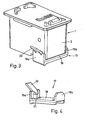
- the ink cartridge 1 is supplemented by (Fig. 3, 4) a closure member 17 to an ink cartridge unit.
- the one-piece closure member 17 comprises a rectangular closure plate 18 and at its opposite ends approximately at right angles protruding parallel retaining wings 19a, b, of which the retaining wing 19a has an obliquely projecting tab 20.
- Die Lasche 20 ist in der Ausbloodung 17 des Geouses 19a anorg.
- Each of the retaining wings 19a, b carries a protruding nose 21 against the respectively opposite retaining wing 19b.
- the closure part 17 is fastened by snap-locking to the housing 2 of the ink cartridge 1 by the lugs 21 engaging with the depressions 16.
- the top of the closure plate 18 presses against the sealing surface 10, so that the outlet opening 12 is reliably and tightly closed.
- the closure member 17 is made of a relatively stiff elastic plastic, e.g. Polypropylene.
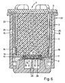
- the ink cartridge 1 forms with an adapter 22 (Figs. 2, 5, 6) an ink jet printhead as used in ink jet printers.
- the adapter 22 has a housing 23, which forms a receptacle 24 open at the top, into which the ink cartridge 1 can be inserted.
- the side walls of the housing 23 are facing each other opposite round detent holes 25, with which the locking cam 15 engage, so that the inserted ink cartridge 1 is locked to the adapter 22.
- the housing 23 carries a nozzle plate (not shown) for the controlled release of ink droplets. Nozzle plates and their control are well known.
- the adapter 22 has a receiving opening 27 surrounded by a stepped frame, in which a sieve-like filter 28 is arranged, which is e.g. formed as a braid of metal wires and the interception of larger particles is used, which could otherwise clog the nozzle of the nozzle plate, with which the receiving opening 27 via a connecting thereto the same cavity 29 and (not shown) lines in communication.
- the effective between the adapter 22 and the ink cartridge 1 latching connection is designed so that the sealing surface 10 presses frontally against the frame of the receiving opening 27, such that of the chamber of the ink cartridge 1 through the outlet opening 12 and the receiving opening 27 to the cavity 29 leading Ink path against the outside, that is sealed against the surrounding areas of the receiving compartment 24, and the ink is passed from the storage body 3 to the nozzle plate without the flow of ink are interrupted by penetrating from the surrounding region of the receiving compartment 24 air or vice versa ink escape into the receptacle 24 could.
- the housing 23 of the adapter 22 is also made of plastic, eg glass fiber reinforced PET.
- the ink cartridge 1 is very easy to use by a rectilinear movement in the receiving compartment 24.
- the sealing of the ink path results automatically and without the insertion of the ink cartridge 1 friction between the seal and mating surfaces, with which it interacts, would arise, which could hinder the insertion. Effortless insertion of a seal on the bottom of the receiving compartment is not required.
- the ink cartridge may be suitable for color printing and may have several, e.g. have three or four separate chambers, each with a storage body, which is impregnated with an ink of a different color and an ink outlet.
- the adapter must then be designed accordingly, with several receiving openings and suitable nozzle plate and control.
- it may be provided with three or four storage compartments each having a receiving opening, each suitable for receiving a single-chamber ink cartridge containing ink of a particular color.
Landscapes
- Ink Jet (AREA)
Description
- Die Erfindung betrifft eine Tintenpatrone sowie eine Tintenpatroneneinheit und einen Tintenstrahldruckkopf, welche jeweils eine derartige Tintenpatrone umfassen für den Einsatz in einem Tintenstrahldrucker.
- Aus der US-6 149 267 A ist eine gattungsgemässe Tintenpatrone bekannt, bei welcher als Tintenauslass lediglich eine Oeffnung in der Wand der Kammer vorgesehen ist. Wird die Tintenpatrone in einen passenden Adapter eingesetzt, so liegt ein Stutzen desselben mit etwas seitlichem Spiel in der Oeffnung. Dies hat den Nachteil, dass dort neben dem Stutzen Tinte austreten kann, welche den Adapter verschmutzt. Umgekehrt kann beim Einsetzen der Tintenpatrone Luft eingeschlossen werden, was u.U. zu einer Unterbrechung des Tintenpfades führt. Daher ist es erforderlich, an der dem Tintenauslass entgegengesetzten Seite des Gehäuses ein Pumpelement vorzusehen, mittels dessen Druck in der Kammer aufgebaut und die Tinte durch die Auslassöffnung getrieben werden kann. Ein solches Pumpelement verteuert jedoch die Tintenpatrone. Ausserdem ist es lästig, dass die nach dem Einsetzen meist schlecht zugängliche Tintenpatrone noch durch Pumpen gebrauchsfertig gemacht werden muss.
- Bei einer im übrigen ähnlichen Lösung (US-5 784 088 A) ist daher der Stutzen des Adapters an seiner Basis von einem Dichtungsring umgeben, der gegen das Gehäuse der Tintenpatrone drückt. Auch diese Lösung ist nicht befriedigend, da der zwischen dem Speicherkörper und dem Dichtungsring liegende Zwischenraum zwischen dem Stutzen und einem ihn aufnehmenden Kragen der Tintenpatrone trotzdem verschmutzen kann. Ausserdem ist der Dichtungsring nur schwer zu montieren, wenn der Adapter ein Aufnahmefach für die Tintenpatrone aufweist, wie es im Hinblick auf eine sichere Befestigung und Führung derselben beim Einsetzen wünschenswert ist.
- Gemäss US-5 767 881 A ist bei sonst ähnlicher Ausbildung an der Aussenseite des Stutzens ein Dichtungsring angeordnet, der mit dem Kragen, der den Stutzen aufnimmt, zusammenwirkt. Der Dichtungsring ist jedoch am Grund des Aufnahmefachs verhältnismässig schwer zu montieren. Ausserdem muss er bei eingesetzter Tintenpatrone etwas zusammengepresst sein, damit die Dichtung zuverlässig wirkt. Daher ist beim Entfernen und beim Einsetzen der Tintenpatrone eine verhältnismässig grosse Reibung zwischen dem Dichtungsring und dem Kragen zu überwinden, was diese Vorgänge erschwert. Der Tintenpfad im Adapter kann leicht unterbrochen werden, da zwischen der vorgeschobenen, von einer porösen Platte verschlossenen Aufnahmeöffnung und einem zwischen derselben und der Düsenplatte eingebauten Sieb grössere Hohlräume liegen. Daher ist auch hier ein Pumpelement erforderlich, das die Tintenpatrone verteuert und ihre Bedienung erschwert.
- Der Erfindung liegt die Aufgabe zu Grunde, eine gattungsgemässe Tintenpatrone anzugeben, welche mit einem einfach aufgebauten Adapter so zusammenwirken kann, dass der Tintenpfad zuverlässig abgedichtet ist, so dass keine störenden Verschmutzungen auftreten können und dass sie zugleich leicht einsetzbar und entfernbar ist. Diese Aufgabe wird durch die Merkmale im Kennzeichen des Anspruchs 1 gelöst.
- Die erfindungsgemässe Tintenpatrone kann durch gerades, im wesentlichen reibungsfreies Einschieben auf einfache Weise eingesetzt werden. Der Tintenpfad zum Adapter ist damit ohne weitere Massnahmen hergestellt. Trotzdem ist ein Austreten von Tinte zuverlässig unterbunden. Die erfindungsgemässe Tintenpatrone kann auch sehr leicht wieder entfernt werden.
- Die Erfindung gibt ausserdem eine Tintenpatroneneinheit an, bei welcher die Auslassöffnung auf sehr einfache Weise zuverlässig verschlossen ist, so dass sie sicher und problemlos transportiert und gelagert werden kann. Zudem wird ein Tintenstrahldruckkopf beschrieben, welcher neben der erfindungsgemässen Tintenpatrone einen Adapter mit Düsenplatte umfasst, an welchem dieselbe befestigbar ist. Der Adapter ist sehr einfach aufgebaut und wirkt so mit der erfindungsgemässen Tintenpatrone zusammen, dass der Tintenpfad zuverlässig abgedichtet ist und eine Unterbrechung desselben nicht eintreten kann.
- Im folgenden wird die Erfindung anhand von Figuren, welche lediglich ein Ausführungsbeispiel darstellen, näher erläutert. Es zeigen
- Fig. 1
- eine Explosionsdarstellung einer erfindungsgemässen Tintenpatrone,
- Fig. 2
- einen Adapter eines erfindungsgemässen Tintenstrahldruckkopfs,
- Fig. 3
- eine erfindungsgemässe Tintenpatroneneinheit,
- Fig. 4
- ein Verschlussteil der Tintenpatroneneinheit nach Fig. 3,
- Fig. 5
- einen erfindungsgemässen Tintenstrahldruckkopf, teilweise geschnitten und
- Fig. 6
- einen Schnitt durch den Tintenstrahldruckkopf nach Fig. 5.
- Die erfindungsgemässe Tintenpatrone 1 weist (Fig. 1, 5, 6) ein Gehäuse 2 auf, das eine Kammer umgibt, welche einen mit Tinte vollgesogenen Speicherkörper 3 aus offenporigem Schaumstoff enthält und die durch einen Deckel 4 mit einer Lüftungsöffnung 5 verschlossen ist. Die Lüftungsöffnung 5 mündet an der Oberseite des Deckels 4 in eine mäanderförmige Vertiefung, die sich am Ende erweitert. Die Vertiefung kann, mit Ausnahme der Erweiterung am Ende, durch z.B. ein Klebeetikett abgedeckt sein und bildet einen Ausdehnungsraum, der erforderlichenfalls Tinte aufnimmt. Am Boden des Gehäuses 2 ist ein Tintenauslass 6 vorgesehen. Dazu weist das Gehäuse dort eine Oeffnung 7 (Fig. 5) auf, in welche eine Dichtung 8 eingesetzt ist.
- Die Dichtung 8 umfasst eine etwa quadratische Kontaktplatte 9, deren Oberseite an der Unterseite des Gehäuses 2 anliegt und deren Unterseite eine freiliegende Dichtfläche 10 bildet sowie einen an deren Oberseite an die Kontaktplatte 9 anschliessenden, mit ihr einstückigen Ring 11. Zur Sicherung gegen Verdrehung ist die Kontaktplatte 9 an einer Ecke etwas verkürzt und stösst dort an einen von der Unterseite des Gehäuse 2 abstehenden Nocken. Im Zentrum der Dichtfläche 10 liegt eine Auslassöffnung 12, an die ein vom Ring 11 umgebener Durchlass anschliesst, der sie mit der Kammer im Inneren des Gehäuses 2 verbindet. Der Ring 11 weist am oberen Ende einen radial nach aussen vorstehenden umlaufenden Kragen 13 auf, welcher an der Innenseite des Gehäuses 2 über den etwas eingesenkten Rand der Oeffnung 7 ragt und so die Dichtung 8 in derselben schnappverriegelt, so dass sie nicht ohne Deformation entfernbar ist. Zugleich verbessert der Kragen 13 die Abdichtung zwischen dem Rand der Oeffnung 7 und der Aussenseite des Ringes 11. In der Auslassöffnung 12 liegt ein mit der Dichtung 8 verbundenes Leitelement 14, ein rundes Plättchen, das aus porösem Material, z.B. aus offenporigem Schaumstoff oder aus parallelen Fasern, die axial vom Inneren der Kammer nach aussen führen, besteht.
- An den Seitenwänden weist das Gehäuse 2 zwei einander gegenüberliegende kugelkalottenförmige flache Rastnocken 15 auf sowie jeweils etwas unterhalb davon, nicht weit von der Unterkante entfernt, rechteckige Vertiefungen 16. Das Gehäuse 2 und der Deckel 4 bestehen aus Kunststoff, vorzugsweise aus Polypropylen. Der Speicherkörper 3 kann aus PUR bestehen und das Leitelement 14, falls es als Schaumstoffkörper ausgebildet ist, ebenfalls, falls es als Faserbündel ausgebildet ist, aus Polyester. Die Kontaktplatte 9 und der Ring 11 bestehen aus einem Material, das elastisch ist und weicher als das Material des Gehäuses 2, z.B. aus einem thermoplastischen Elastomer.
- Für Versand und Lagerung ist die Tintenpatrone 1 durch (Fig. 3, 4) ein Verschlussteil 17 zu einer Tintenpatroneneinheit ergänzt. Das einstückige Verschlussteil 17 umfasst eine rechteckige Verschlussplatte 18 sowie an deren gegenüberliegenden Enden etwa rechtwinklig abstehende parallele Halteflügel 19a,b, von denen der Halteflügel 19a eine schräg abstehende Lasche 20 aufweist. Jeder der Halteflügel 19a,b trägt eine gegen den jeweils gegenüberliegenden Halteflügel 19b;a vorspringende Nase 21. Das Verschlussteil 17 ist durch Schnappverriegelung am Gehäuse 2 der Tintenpatrone 1 befestigt, indem die Nasen 21 mit den Vertiefungen 16 eingreifen. Die Oberseite der Verschlussplatte 18 drückt dabei gegen die Dichtfläche 10, so dass die Auslassöffnung 12 zuverlässig und dicht verschlossen ist. Durch Druck gegen die Oberseite der Lasche 20 kann die Schnappverriegelung gelöst und das Verschlussteil 17 abgenommen werden. Das Verschlussteil 17 besteht aus einem verhältnismässig steifen elastischen Kunststoff, z.B. Polypropylen.
- Die Tintenpatrone 1 bildet mit einem Adapter 22 (Fig. 2, 5, 6) einen Tintenstrahldruckkopf, wie er in Tintenstrahldruckern verwendet wird. Der Adapter 22 weist ein Gehäuse 23 auf, das ein oben offenes Aufnahmefach 24 bildet, in welches die Tintenpatrone 1 einsetzbar ist. Die Seitenwände des Gehäuses 23 weisen einander gegenüberliegende runde Rastlöcher 25 auf, mit welchen die Rastnocken 15 eingreifen, so dass die eingesetzte Tintenpatrone 1 mit dem Adapter 22 verrastet ist. Am oberen Rand weisen sie ausserdem halbkreisförmige Ausnehmungen 26 auf, welche das Einsetzen und Entfernen der Tintenpatrone 1 erleichtern.
- An der Unterseite trägt das Gehäuse 23 eine Düsenplatte (nicht dargestellt) zur gesteuerten Abgabe von Tintentropfen. Düsenplatten und ihre Steuerung sind wohlbekannt. Am Grund des Aufnahmefaches 24 weist der Adapter 22 eine von einem abgesetzten Rahmen umgebene Aufnahmeöffnung 27 auf, in welcher ein siebartiger Filter 28 angeordnet ist, der z.B. als Geflecht aus Metalldrähten ausgebildet ist und dem Abfangen grösserer Partikel dient, die sonst die Düsen der Düsenplatte verstopfen könnten, mit denen die Aufnahmeöffnung 27 über einen an dieselbe anschliessenden Hohlraum 29 und (nicht dargestellte) Leitungen in Verbindung steht.
- Die zwischen dem Adapter 22 und der Tintenpatrone 1 wirksame Rastverbindung ist so angelegt, dass die Dichtfläche 10 frontal gegen den Rahmen der Aufnahmeöffnung 27 drückt, derart, dass der von der Kammer der Tintenpatrone 1 durch die Auslassöffnung 12 und die Aufnahmeöffnung 27 zum Hohlraum 29 führende Tintenpfad gegen aussen, d.h. gegen die umgebenden Bereiche des Aufnahmefachs 24, zuverlässig abgedichtet ist und die Tinte vom Speicherkörper 3 zur Düsenplatte geleitet wird, ohne dass der Tintenfluss durch aus dem umgebenden Bereich des Aufnahmefachs 24 eindringende Luft unterbrochen werden oder umgekehrt Tinte ins Aufnahmefach 24 austreten könnte. Das Gehäuse 23 des Adapters 22 besteht ebenfalls aus Kunststoff, z.B. glasfaserverstärktem PET.
- Die Tintenpatrone 1 ist sehr einfach durch eine geradlinige Bewegung in das Aufnahmefach 24 einsetzbar. Die Abdichtung des Tintenpfades ergibt sich dabei von selbst und ohne dass beim Einsetzen der Tintenpatrone 1 Reibung zwischen der Dichtung und Gegenflächen, mit denen sie zusammenwirkt, entstünde, welche das Einsetzen behindern könnte. Mühsames Einsetzen einer Dichtung auf dem Grund des Aufnahmefachs ist nicht erforderlich.
- Die beschriebene Tintenpatrone sowie das Verschlussteil und der Adapter können vielfach abgewandelt werden. Insbesondere kann die Tintenpatrone für Farbdruck geeignet sein und mehrere, z.B. drei oder vier getrennte Kammern aufweisen, jede mit einem Speicherkörper, der mit einer Tinte einer anderen Farbe getränkt ist und einem Tintenauslass. Der Adapter muss dann entsprechend ausgebildet sein, mit mehreren Aufnahmeöffnungen und geeigneter Düsenplatte und Steuerung. Alternativ kann er mit drei oder vier Aufnahmefächern mit jeweils einer Aufnahmeöffnung versehen sein, die jeweils zur Aufnahme einer Tintenpatrone mit einer einzigen Kammer, welche Tinte einer bestimmten Farbe enthält, geeignet sind.
-
- 1
- Tintenpatrone
- 2
- Gehäuse
- 3
- Speicherkörper
- 4
- Deckel
- 5
- Lüftungsöffnung
- 6
- Tintenauslass
- 7
- Oeffnung
- 8
- Dichtung
- 9
- Kontaktplatte
- 10
- Dichtfläche
- 11
- Ring
- 12
- Auslassöffnung
- 13
- Kragen
- 14
- Leitelement
- 15
- Rastnocken
- 16
- Vertiefung
- 17
- Verschlussteil
- 18
- Verschlussplatte
- 19a,b
- Halteflügel
- 20
- Lasche
- 21
- Nase
- 22
- Adapter
- 23
- Gehäuse
- 24
- Aufnahmefach
- 25
- Rastloch
- 26
- Ausnehmung
- 27
- Aufnahmeöffnung
- 28
- Filter
- 29
- Hohlraum
Claims (15)
- Tintenpatrone (1) für einen Tintenstrahldrucker, mit einem Gehäuse (2), welches mindestens eine Kammer umschliesst, die an einer Unterseite einen Tintenauslass (6) mit einer Oeffnung (7) aufweist sowie an einer Oberseite eine Lüftungsöffnung (5) und welche durch einen porösen Speicherkörper (3) zur Aufnahme von Tinte ausgefüllt ist, dadurch gekennzeichnet, dass der Tintenauslass (6) eine in die Oeffnung (7) eingesetzte ringartige Dichtung (8) aus weichem elastischen Material umfasst, die eine an der Aussenseite des Gehäuses (2) liegende, eine Auslassöffnung (12) umgebende Dichtfläche (10) bildet.
- Tintenpatrone nach Anspruch 1, dadurch gekennzeichnet, dass die Dichtung (8) eine an der Aussenseite des Gehäuses (2) anliegende Kontaktplatte (9) umfasst sowie einen an der dem Gehäuse (2) zugewandten Seite anschliessenden Ring (11), der einen an die Auslassöffnung (12) anschliessenden Durchlass umgibt und dessen Aussenseite am Rand der Oeffnung (7) anliegt, während er an seinem von der Kontaktplatte (9) abgewandten Ende einen nach aussen vorstehenden, vorzugsweise als umlaufender Kragen (13) ausgebildeten Vorsprung aufweist, welcher an der Innenseite des Gehäuses (2) den Rand der Oeffnung (7) überkragt, so dass die Dichtung (8) in der Oeffnung (7) schnappverriegelt ist.
- Tintenpatrone nach Anspruch 2, dadurch gekennzeichnet, dass die Kontaktplatte (9) im wesentlichen rechteckig, insbesondere quadratisch ist.
- Tintenpatrone nach einem der Ansprüche 1 bis 3, dadurch gekennzeichnet, dass die Dichtung (8) aus einem Elastomer besteht.
- Tintenpatrone nach einem der Ansprüche 1 bis 4, dadurch gekennzeichnet, dass in der Auslassöffnung (12) ein Leitelement (14) aus porösem Material liegt.
- Tintenpatrone nach Anspruch 5, dadurch gekennzeichnet, dass das Leitelement (14) mit der Dichtung (8) verbunden ist.
- Tintenpatrone nach Anspruch 5 oder 6, dadurch gekennzeichnet, dass das Leitelement (14) im wesentlichen aus vom Inneren der Kammer nach aussen gerichteten parallelen Fasern besteht.
- Tintenpatroneneinheit mit einer Tintenpatrone nach einem der Ansprüche 1 bis 7, dadurch gekennzeichnet, dass sie ausserdem ein Verschlussteil (17) umfasst, welches derart abnehmbar an der Tintenpatrone (1) befestigt ist, dass es die Auslassöffnung (12) verschliesst und an der Dichtfläche (10) anliegt.
- Tintenpatroneneinheit nach Anspruch 8, dadurch gekennzeichnet, dass das Verschlussteil (17) elastisch ist und mittels einer Schnappverriegelung an der Tintenpatrone (1) befestigt ist.
- Tintenpatroneneinheit nach Anspruch 9, dadurch gekennzeichnet, dass das Verschlussteil (17) klammerartig ausgebildet ist mit einer die Auslassöffnung (12) verschliessenden Verschlussplatte (18) und zwei etwa parallel von derselben abstehenden Halteflügeln (19a, 19b), welche an entgegengesetzten Seiten des Gehäuses (2) der Tintenpatrone (1) anliegen.
- Tintenstrahldruckkopf mit mindestens einer Tintenpatrone (1) nach einem der Ansprüche 1 bis 7, dadurch gekennzeichnet, dass er einen Adapter (22) umfasst, an welchem die Tintenpatrone (1) befestigbar ist, mit, an einer Unterseite, einer mit Düsenöffnungen versehenen Düsenplatte und mit einer Aufnahmeöffnung (27) für Tinte, welche mit mindestens einem Teil der Düsenöffnungen in Verbindung steht und welche von einem Rahmen umgeben ist, der bei befestigter Tintenpatrone (1) die Auslassöffnung (12) umgebend an deren Dichtfläche (10) anliegt.
- Tintenstrahldruckkopf nach Anspruch 11, dadurch gekennzeichnet, dass der Adapter (22) ein Aufnahmefach (24) aufweist, in welche die Tintenpatrone (1) einsetzbar ist und an dessen Grund die Aufnahmeöffnung (27) angeordnet ist.
- Tintenstrahldruckkopf nach Anspruch 11 oder 12, dadurch gekennzeichnet, dass im Adapter (22) zwischen der Aufnahmeöffnung (27) und der Düsenplatte ein insbesondere siebartiger Filter (28) liegt.
- Tintenstrahldruckkopf nach Anspruch 13, dadurch gekennzeichnet, dass der Filter (28) in der Aufnahmeöffnung (27) angeordnet ist.
- Tintenstrahldruckkopf nach einem der Ansprüche 11 bis 14, dadurch gekennzeichnet, dass die Tintenpatrone (1) mit dem Adapter (22) verrastet ist.
Priority Applications (14)
| Application Number | Priority Date | Filing Date | Title |
|---|---|---|---|
| AT03026434T ATE333371T1 (de) | 2003-11-19 | 2003-11-19 | Tintenpatrone, tintenpatroneneinheit sowie tintenstrahldruckkopf |
| EP03026434A EP1533125B3 (de) | 2003-11-19 | 2003-11-19 | Tintenpatrone, Tintenpatroneneinheit sowie Tintenstrahldruckkopf |
| DE50304298T DE50304298D1 (de) | 2003-11-19 | 2003-11-19 | Tintenpatrone, Tintenpatroneneinheit sowie Tintenstrahldruckkopf |
| ES03026434T ES2268261T7 (es) | 2003-11-19 | 2003-11-19 | Cartucho de tinta, grupo del cartucho de tinta y cabezal de impresion por chorro de tinta. |
| US10/985,952 US7625078B2 (en) | 2003-11-19 | 2004-11-12 | Ink cartridge, ink cartridge unit and inkjet printing head |
| AU2004229077A AU2004229077B2 (en) | 2003-11-19 | 2004-11-12 | Ink cartridge, ink cartridge unit and inkjet printing head |
| TW093134912A TWI255234B (en) | 2003-11-19 | 2004-11-15 | Ink cartridge, ink cartridge unit and inkjet printing head |
| JP2004334271A JP2005145074A (ja) | 2003-11-19 | 2004-11-18 | インクカートリッジ、インクカートリッジユニットおよびインクジェットプリントヘッド |
| ZA200409188A ZA200409188B (en) | 2003-11-19 | 2004-11-18 | Ink cartridge, ink cartridge unit and inkjet printing head. |
| KR1020040095332A KR100730505B1 (ko) | 2003-11-19 | 2004-11-19 | 잉크 카트리지, 잉크 카트리지 유닛, 및 잉크젯 프린팅 헤드 |
| BR0405103-3A BRPI0405103A (pt) | 2003-11-19 | 2004-11-19 | Cartucho de tinta, unidade de cartucho de tinta e cabeçote de impressão a jato de tinta |
| MYPI20044797A MY129388A (en) | 2003-11-19 | 2004-11-19 | Ink catridge, ink cartridge unit and inkjet printing head |
| MXPA04011541A MXPA04011541A (es) | 2003-11-19 | 2004-11-19 | Cartucho de tinta, unidad de cartucho de tinta y cabeza de impresion de chorro de tinta. |
| CNB2004100949802A CN100346977C (zh) | 2003-11-19 | 2004-11-19 | 墨盒、墨盒单元与喷墨打印头 |
Applications Claiming Priority (1)
| Application Number | Priority Date | Filing Date | Title |
|---|---|---|---|
| EP03026434A EP1533125B3 (de) | 2003-11-19 | 2003-11-19 | Tintenpatrone, Tintenpatroneneinheit sowie Tintenstrahldruckkopf |
Publications (3)
| Publication Number | Publication Date |
|---|---|
| EP1533125A1 EP1533125A1 (de) | 2005-05-25 |
| EP1533125B1 true EP1533125B1 (de) | 2006-07-19 |
| EP1533125B3 EP1533125B3 (de) | 2008-12-17 |
Family
ID=34429384
Family Applications (1)
| Application Number | Title | Priority Date | Filing Date |
|---|---|---|---|
| EP03026434A Expired - Lifetime EP1533125B3 (de) | 2003-11-19 | 2003-11-19 | Tintenpatrone, Tintenpatroneneinheit sowie Tintenstrahldruckkopf |
Country Status (14)
| Country | Link |
|---|---|
| US (1) | US7625078B2 (de) |
| EP (1) | EP1533125B3 (de) |
| JP (1) | JP2005145074A (de) |
| KR (1) | KR100730505B1 (de) |
| CN (1) | CN100346977C (de) |
| AT (1) | ATE333371T1 (de) |
| AU (1) | AU2004229077B2 (de) |
| BR (1) | BRPI0405103A (de) |
| DE (1) | DE50304298D1 (de) |
| ES (1) | ES2268261T7 (de) |
| MX (1) | MXPA04011541A (de) |
| MY (1) | MY129388A (de) |
| TW (1) | TWI255234B (de) |
| ZA (1) | ZA200409188B (de) |
Cited By (1)
| Publication number | Priority date | Publication date | Assignee | Title |
|---|---|---|---|---|
| CN101618634B (zh) * | 2008-06-30 | 2011-05-04 | 兄弟工业株式会社 | 用于墨盒的转接器 |
Families Citing this family (9)
| Publication number | Priority date | Publication date | Assignee | Title |
|---|---|---|---|---|
| DE102006036716B3 (de) * | 2006-06-02 | 2007-09-27 | Artech Gmbh Design + Production In Plastic | Vorrichtung und Verfahren zur Umrüstung eines Druckers |
| CN200954714Y (zh) * | 2006-09-30 | 2007-10-03 | 聂瑞权 | 一种头盒分体式打印头墨盒 |
| CN200984864Y (zh) * | 2006-12-18 | 2007-12-05 | 刘春云 | 一种带有打印头的再生墨盒 |
| CN200995522Y (zh) * | 2007-01-09 | 2007-12-26 | 聂瑞权 | 一种打印头墨盒用固定压盖 |
| CN102161278B (zh) * | 2008-06-30 | 2014-03-05 | 兄弟工业株式会社 | 用于墨盒的转接器 |
| JP5724398B2 (ja) * | 2011-01-14 | 2015-05-27 | セイコーエプソン株式会社 | 容器ユニット、及び、液体噴射システム |
| AU2015100932B4 (en) * | 2015-07-14 | 2015-11-26 | The Trustee For Rihac Trading Trust | Improved Ink Refill Cartridge for all-in-one Printhead-ink Cartridge |
| CN105034600A (zh) * | 2015-08-27 | 2015-11-11 | 石立公 | 一种无刚性内芯的随机打标头 |
| CN110027324A (zh) * | 2019-05-06 | 2019-07-19 | 珠海艾派克微电子有限公司 | 喷嘴墨盒、喷墨组件及电路基板 |
Citations (3)
| Publication number | Priority date | Publication date | Assignee | Title |
|---|---|---|---|---|
| US5767881A (en) * | 1995-05-10 | 1998-06-16 | Pelikan Produktions Ag | Print head for an ink jet printer |
| US5784088A (en) * | 1993-07-20 | 1998-07-21 | Canon Kabushiki Kaisha | Ink jet recording apparatus using recording unit with ink cartridge having ink inducing element |
| US6149267A (en) * | 1992-03-10 | 2000-11-21 | Pelikan Produktions Ag | Ink cartridge for a printing head of an ink jet printer |
Family Cites Families (26)
| Publication number | Priority date | Publication date | Assignee | Title |
|---|---|---|---|---|
| IT1232551B (it) | 1989-07-13 | 1992-02-19 | Olivetti & Co Spa | Testina di stampa per una stampante termica a getto d'inchiostro |
| US5790158A (en) * | 1992-01-28 | 1998-08-04 | Seiko Epson Corporation | Ink-jet recording apparatus and ink tank cartridge therefor |
| US5359356A (en) * | 1992-09-30 | 1994-10-25 | Ecklund Joel E | Collapsible jet-ink container assembly and method |
| JP3199092B2 (ja) * | 1993-11-05 | 2001-08-13 | セイコーエプソン株式会社 | プリンタ用のインクカートリッジ |
| US6188417B1 (en) * | 1994-10-31 | 2001-02-13 | Hewlett-Packard Company | Fluidic adapter for use with an inkjet print cartridge having an internal pressure regulator |
| US5793396A (en) * | 1994-12-12 | 1998-08-11 | Brother Kogyo Kabushiki Kaisha | Ink-supply connecting member and ink ejection system |
| US5745139A (en) * | 1994-12-12 | 1998-04-28 | Brother Kogyo Kabushiki Kaisha | Ink feed connecting member |
| JPH08192518A (ja) | 1995-01-18 | 1996-07-30 | Matsushita Electric Ind Co Ltd | インクタンクおよびインクジェット記録装置 |
| PT745480E (pt) * | 1995-05-16 | 2000-06-30 | Dynamic Cassette Int | Cartucho de tinta para impressora de jacto de tinta |
| US5793356A (en) * | 1995-07-31 | 1998-08-11 | Microsoft Corporation | System and method for the software emulation of a computer joystick |
| US5917525A (en) * | 1995-10-30 | 1999-06-29 | Pelikan Produktions Ag | Ink cartridge for a print head of an ink-jet printer |
| JP3687706B2 (ja) | 1996-09-13 | 2005-08-24 | 富士ゼロックス株式会社 | プリンタおよびインクタンク |
| JPH10250104A (ja) * | 1997-03-12 | 1998-09-22 | Seiko Epson Corp | インクジェット式記録装置用インクカートリッジ、及びその製造方法 |
| JPH10272782A (ja) * | 1997-03-31 | 1998-10-13 | Brother Ind Ltd | インクジェット記録装置 |
| JPH10329329A (ja) | 1997-06-03 | 1998-12-15 | S T Sangyo Kk | インクジェット記録装置用インクカートリッジ |
| JP3823588B2 (ja) * | 1998-08-05 | 2006-09-20 | ブラザー工業株式会社 | インクジェット記録装置 |
| JP2000062259A (ja) * | 1998-08-19 | 2000-02-29 | Ricoh Co Ltd | インクジェット記録装置 |
| JP3897490B2 (ja) * | 1999-08-24 | 2007-03-22 | キヤノン株式会社 | 被覆ゴム部材、記録ヘッド、保管箱およびインクジェット記録装置 |
| JP2001260172A (ja) | 2000-03-17 | 2001-09-25 | Canon Inc | 複数の樹脂材料から構成した成形品、及び収容容器、成形品の材料回収方法、成形品の分離方法、成形品の利用方法、成形品の成形方法、ならびに、記録材料収容容器のキャップ部材 |
| US6935730B2 (en) * | 2000-04-03 | 2005-08-30 | Unicorn Image Products Co. Ltd. Of Zhuhai | One-way valve, valve unit assembly, and ink cartridge using the same |
| TW503183B (en) * | 2000-06-19 | 2002-09-21 | Ind Tech Res Inst | Ink cartridge |
| CN1165432C (zh) * | 2000-07-31 | 2004-09-08 | 珠海飞马耗材有限公司 | 一种在出墨口设置有密封件的墨盒装置 |
| US20020075366A1 (en) * | 2000-12-20 | 2002-06-20 | Xerox Corporation. | Liquid ink tank with integral capillary |
| US6854836B2 (en) * | 2001-10-05 | 2005-02-15 | Canon Kabushiki Kaisha | Liquid container, liquid supply system, liquid using apparatus, ink tank, ink supply system, inkjet print head and print apparatus |
| US7128380B2 (en) * | 2002-04-10 | 2006-10-31 | Canon Kabushiki Kaisha | Recording liquid container, ink jet recording apparatus, and cartridge collecting apparatus |
| US6648458B2 (en) * | 2002-04-23 | 2003-11-18 | Hewlett-Packard Development Company, L.P. | Pinch seal providing fluid interconnects between fluid delivery system components |
-
2003
- 2003-11-19 EP EP03026434A patent/EP1533125B3/de not_active Expired - Lifetime
- 2003-11-19 AT AT03026434T patent/ATE333371T1/de active
- 2003-11-19 ES ES03026434T patent/ES2268261T7/es active Active
- 2003-11-19 DE DE50304298T patent/DE50304298D1/de not_active Expired - Lifetime
-
2004
- 2004-11-12 AU AU2004229077A patent/AU2004229077B2/en not_active Ceased
- 2004-11-12 US US10/985,952 patent/US7625078B2/en not_active Expired - Fee Related
- 2004-11-15 TW TW093134912A patent/TWI255234B/zh not_active IP Right Cessation
- 2004-11-18 JP JP2004334271A patent/JP2005145074A/ja active Pending
- 2004-11-18 ZA ZA200409188A patent/ZA200409188B/xx unknown
- 2004-11-19 MX MXPA04011541A patent/MXPA04011541A/es active IP Right Grant
- 2004-11-19 KR KR1020040095332A patent/KR100730505B1/ko not_active Expired - Fee Related
- 2004-11-19 CN CNB2004100949802A patent/CN100346977C/zh not_active Expired - Fee Related
- 2004-11-19 BR BR0405103-3A patent/BRPI0405103A/pt not_active IP Right Cessation
- 2004-11-19 MY MYPI20044797A patent/MY129388A/en unknown
Patent Citations (3)
| Publication number | Priority date | Publication date | Assignee | Title |
|---|---|---|---|---|
| US6149267A (en) * | 1992-03-10 | 2000-11-21 | Pelikan Produktions Ag | Ink cartridge for a printing head of an ink jet printer |
| US5784088A (en) * | 1993-07-20 | 1998-07-21 | Canon Kabushiki Kaisha | Ink jet recording apparatus using recording unit with ink cartridge having ink inducing element |
| US5767881A (en) * | 1995-05-10 | 1998-06-16 | Pelikan Produktions Ag | Print head for an ink jet printer |
Cited By (1)
| Publication number | Priority date | Publication date | Assignee | Title |
|---|---|---|---|---|
| CN101618634B (zh) * | 2008-06-30 | 2011-05-04 | 兄弟工业株式会社 | 用于墨盒的转接器 |
Also Published As
| Publication number | Publication date |
|---|---|
| ES2268261T3 (es) | 2007-03-16 |
| MXPA04011541A (es) | 2005-05-23 |
| BRPI0405103A (pt) | 2005-07-19 |
| KR20050048533A (ko) | 2005-05-24 |
| AU2004229077B2 (en) | 2006-11-23 |
| US7625078B2 (en) | 2009-12-01 |
| EP1533125A1 (de) | 2005-05-25 |
| EP1533125B3 (de) | 2008-12-17 |
| ATE333371T1 (de) | 2006-08-15 |
| KR100730505B1 (ko) | 2007-06-22 |
| CN1618613A (zh) | 2005-05-25 |
| CN100346977C (zh) | 2007-11-07 |
| AU2004229077A1 (en) | 2005-06-02 |
| TWI255234B (en) | 2006-05-21 |
| TW200531844A (en) | 2005-10-01 |
| MY129388A (en) | 2007-03-30 |
| DE50304298D1 (de) | 2006-08-31 |
| JP2005145074A (ja) | 2005-06-09 |
| US20060001709A1 (en) | 2006-01-05 |
| ZA200409188B (en) | 2005-07-12 |
| ES2268261T7 (es) | 2009-06-18 |
Similar Documents
| Publication | Publication Date | Title |
|---|---|---|
| DE602004011978T2 (de) | Ventil, Tintenpatrone mit diesem Ventil und Tintenversorgungsverfahren | |
| EP1533125B1 (de) | Tintenpatrone, Tintenpatroneneinheit sowie Tintenstrahldruckkopf | |
| DE102009006430A1 (de) | Austragvorrichtung | |
| DE60030662T2 (de) | Tintenstrahlaufzeichnungsgerät | |
| EP0800869A1 (de) | Austragvorrichtung für Medien | |
| DE8411409U1 (de) | Entgasungsventil fuer lager- und/oder transportbehaelter | |
| EP0662351A2 (de) | Austragvorrichtung für Medien | |
| DE602004002507T2 (de) | Tintenstrahlaufzeichnungsgerät und Tintenpatrone | |
| EP1987888B1 (de) | Austragvorrichtung | |
| EP0780234B1 (de) | Flüssigkeitspatrone und Druckkopf für einen Ink-Jet-Printer | |
| DE102008034509A1 (de) | Zerstäuber | |
| WO2005025875A1 (de) | Tintenpatrone | |
| EP2110606A2 (de) | Gewerbliches Gargerät, insbesondere Heissluftdämpfer | |
| DE102011010277A1 (de) | Funktionskopf für einen Duftstoffbehälter | |
| EP1609643B1 (de) | Luftverbesserungsvorrichtung zur Verwendung in Kraftfahrzeugen und Kartusche für die Luftverbesserungsvorrichtung | |
| DE19614364B4 (de) | Druckkopf für einen Ink-Jet-Printer | |
| DE102019005326A1 (de) | Filtervorrichtung | |
| DE10220469A1 (de) | Behälteranordnung zum Entnehmen und Applizieren von Teilmengen eines flüssigen Produkts | |
| DE102014003486A1 (de) | Filterpatrone für eine Sicherheitswerkbank und Sicherheitswerkbank mit mindestens einer Filterpatrone | |
| EP2121331A1 (de) | Vorrichtung zur wiederbefüllung einer tintenpatrone für einen tintenstrahldrucker | |
| EP0966331B1 (de) | Kolben zum Einsetzen in eine gefüllte Kartusche | |
| EP0173939A1 (de) | Deckel für die Düsen eines Unterdrucktintendruckkopfes | |
| EP3311928B1 (de) | Kartuschenkolben mit entlüftungsventil | |
| DE4434186A1 (de) | Druckkopf für einen Tintenstrahldrucker und Vorrichtung zum Wiederbefüllen eines derartigen Druckkopfs | |
| EP2214908A1 (de) | Tintenpatrone, insbesondere für einen tintenstrahldrucker |
Legal Events
| Date | Code | Title | Description |
|---|---|---|---|
| PUAI | Public reference made under article 153(3) epc to a published international application that has entered the european phase |
Free format text: ORIGINAL CODE: 0009012 |
|
| AK | Designated contracting states |
Kind code of ref document: A1 Designated state(s): AT BE BG CH CY CZ DE DK EE ES FI FR GB GR HU IE IT LI LU MC NL PT RO SE SI SK TR |
|
| AX | Request for extension of the european patent |
Extension state: AL LT LV MK |
|
| 17P | Request for examination filed |
Effective date: 20050922 |
|
| GRAP | Despatch of communication of intention to grant a patent |
Free format text: ORIGINAL CODE: EPIDOSNIGR1 |
|
| AKX | Designation fees paid |
Designated state(s): AT BE BG CH CY CZ DE DK EE ES FI FR GB GR HU IE IT LI LU MC NL PT RO SE SI SK TR |
|
| GRAS | Grant fee paid |
Free format text: ORIGINAL CODE: EPIDOSNIGR3 |
|
| GRAA | (expected) grant |
Free format text: ORIGINAL CODE: 0009210 |
|
| AK | Designated contracting states |
Kind code of ref document: B1 Designated state(s): AT BE BG CH CY CZ DE DK EE ES FI FR GB GR HU IE IT LI LU MC NL PT RO SE SI SK TR |
|
| PG25 | Lapsed in a contracting state [announced via postgrant information from national office to epo] |
Ref country code: IT Free format text: LAPSE BECAUSE OF FAILURE TO SUBMIT A TRANSLATION OF THE DESCRIPTION OR TO PAY THE FEE WITHIN THE PRESCRIBED TIME-LIMIT;WARNING: LAPSES OF ITALIAN PATENTS WITH EFFECTIVE DATE BEFORE 2007 MAY HAVE OCCURRED AT ANY TIME BEFORE 2007. THE CORRECT EFFECTIVE DATE MAY BE DIFFERENT FROM THE ONE RECORDED. Effective date: 20060719 Ref country code: IE Free format text: LAPSE BECAUSE OF FAILURE TO SUBMIT A TRANSLATION OF THE DESCRIPTION OR TO PAY THE FEE WITHIN THE PRESCRIBED TIME-LIMIT Effective date: 20060719 Ref country code: SK Free format text: LAPSE BECAUSE OF FAILURE TO SUBMIT A TRANSLATION OF THE DESCRIPTION OR TO PAY THE FEE WITHIN THE PRESCRIBED TIME-LIMIT Effective date: 20060719 Ref country code: SI Free format text: LAPSE BECAUSE OF FAILURE TO SUBMIT A TRANSLATION OF THE DESCRIPTION OR TO PAY THE FEE WITHIN THE PRESCRIBED TIME-LIMIT Effective date: 20060719 Ref country code: FI Free format text: LAPSE BECAUSE OF FAILURE TO SUBMIT A TRANSLATION OF THE DESCRIPTION OR TO PAY THE FEE WITHIN THE PRESCRIBED TIME-LIMIT Effective date: 20060719 Ref country code: RO Free format text: LAPSE BECAUSE OF FAILURE TO SUBMIT A TRANSLATION OF THE DESCRIPTION OR TO PAY THE FEE WITHIN THE PRESCRIBED TIME-LIMIT Effective date: 20060719 |
|
| REG | Reference to a national code |
Ref country code: GB Ref legal event code: FG4D Free format text: NOT ENGLISH |
|
| REG | Reference to a national code |
Ref country code: CH Ref legal event code: EP |
|
| REG | Reference to a national code |
Ref country code: IE Ref legal event code: FG4D Free format text: LANGUAGE OF EP DOCUMENT: GERMAN |
|
| REF | Corresponds to: |
Ref document number: 50304298 Country of ref document: DE Date of ref document: 20060831 Kind code of ref document: P |
|
| REG | Reference to a national code |
Ref country code: CH Ref legal event code: NV Representative=s name: ZIMMERLI, WAGNER & PARTNER AG |
|
| PG25 | Lapsed in a contracting state [announced via postgrant information from national office to epo] |
Ref country code: BG Free format text: LAPSE BECAUSE OF FAILURE TO SUBMIT A TRANSLATION OF THE DESCRIPTION OR TO PAY THE FEE WITHIN THE PRESCRIBED TIME-LIMIT Effective date: 20061019 Ref country code: SE Free format text: LAPSE BECAUSE OF FAILURE TO SUBMIT A TRANSLATION OF THE DESCRIPTION OR TO PAY THE FEE WITHIN THE PRESCRIBED TIME-LIMIT Effective date: 20061019 Ref country code: DK Free format text: LAPSE BECAUSE OF FAILURE TO SUBMIT A TRANSLATION OF THE DESCRIPTION OR TO PAY THE FEE WITHIN THE PRESCRIBED TIME-LIMIT Effective date: 20061019 |
|
| GBT | Gb: translation of ep patent filed (gb section 77(6)(a)/1977) |
Effective date: 20060928 |
|
| PG25 | Lapsed in a contracting state [announced via postgrant information from national office to epo] |
Ref country code: BE Free format text: LAPSE BECAUSE OF NON-PAYMENT OF DUE FEES Effective date: 20061130 Ref country code: MC Free format text: LAPSE BECAUSE OF NON-PAYMENT OF DUE FEES Effective date: 20061130 |
|
| PG25 | Lapsed in a contracting state [announced via postgrant information from national office to epo] |
Ref country code: PT Free format text: LAPSE BECAUSE OF FAILURE TO SUBMIT A TRANSLATION OF THE DESCRIPTION OR TO PAY THE FEE WITHIN THE PRESCRIBED TIME-LIMIT Effective date: 20061219 |
|
| ET | Fr: translation filed | ||
| REG | Reference to a national code |
Ref country code: IE Ref legal event code: FD4D |
|
| REG | Reference to a national code |
Ref country code: ES Ref legal event code: FG2A Ref document number: 2268261 Country of ref document: ES Kind code of ref document: T3 |
|
| PLBE | No opposition filed within time limit |
Free format text: ORIGINAL CODE: 0009261 |
|
| 26N | No opposition filed |
Effective date: 20070420 |
|
| BERE | Be: lapsed |
Owner name: 3T SUPPLIES A.G. Effective date: 20061130 |
|
| PLCP | Request for limitation filed |
Free format text: ORIGINAL CODE: EPIDOSNLIM1 |
|
| PLCQ | Request for limitation of patent found admissible |
Free format text: ORIGINAL CODE: 0009231 |
|
| LIM1 | Request for limitation found admissible |
Free format text: SEQUENCE NO: 1; FILED AFTER OPPOSITION PERIOD Filing date: 20080225 |
|
| PG25 | Lapsed in a contracting state [announced via postgrant information from national office to epo] |
Ref country code: GR Free format text: LAPSE BECAUSE OF FAILURE TO SUBMIT A TRANSLATION OF THE DESCRIPTION OR TO PAY THE FEE WITHIN THE PRESCRIBED TIME-LIMIT Effective date: 20061020 |
|
| PG25 | Lapsed in a contracting state [announced via postgrant information from national office to epo] |
Ref country code: EE Free format text: LAPSE BECAUSE OF FAILURE TO SUBMIT A TRANSLATION OF THE DESCRIPTION OR TO PAY THE FEE WITHIN THE PRESCRIBED TIME-LIMIT Effective date: 20060719 |
|
| PLCR | Communication despatched that request for limitation of patent was allowed |
Free format text: ORIGINAL CODE: 0009245 |
|
| PG25 | Lapsed in a contracting state [announced via postgrant information from national office to epo] |
Ref country code: LU Free format text: LAPSE BECAUSE OF NON-PAYMENT OF DUE FEES Effective date: 20061119 Ref country code: HU Free format text: LAPSE BECAUSE OF FAILURE TO SUBMIT A TRANSLATION OF THE DESCRIPTION OR TO PAY THE FEE WITHIN THE PRESCRIBED TIME-LIMIT Effective date: 20070120 Ref country code: TR Free format text: LAPSE BECAUSE OF FAILURE TO SUBMIT A TRANSLATION OF THE DESCRIPTION OR TO PAY THE FEE WITHIN THE PRESCRIBED TIME-LIMIT Effective date: 20060719 |
|
| PLCN | Payment of fee for limitation of patent |
Free format text: ORIGINAL CODE: EPIDOSNRAL3 |
|
| PUAM | (expected) publication of b3 document |
Free format text: ORIGINAL CODE: 0009410 |
|
| STAA | Information on the status of an ep patent application or granted ep patent |
Free format text: STATUS: THE PATENT HAS BEEN LIMITED |
|
| PG25 | Lapsed in a contracting state [announced via postgrant information from national office to epo] |
Ref country code: CY Free format text: LAPSE BECAUSE OF FAILURE TO SUBMIT A TRANSLATION OF THE DESCRIPTION OR TO PAY THE FEE WITHIN THE PRESCRIBED TIME-LIMIT Effective date: 20060719 |
|
| REG | Reference to a national code |
Ref country code: CH Ref legal event code: AEN Free format text: BESCHRAENKUNGANTRAG GUTGEHEISSEN |
|
| REG | Reference to a national code |
Ref country code: CH Ref legal event code: PFA Owner name: 3T SUPPLIES AG Free format text: 3T SUPPLIES AG#CHALTENBODENSTRASSE 6#8834 SCHINDELLEGI (CH) -TRANSFER TO- 3T SUPPLIES AG#CHALTENBODENSTRASSE 6#8834 SCHINDELLEGI (CH) |
|
| REG | Reference to a national code |
Ref country code: CH Ref legal event code: NV Representative=s name: WAGNER PATENT AG, CH |
|
| PGFP | Annual fee paid to national office [announced via postgrant information from national office to epo] |
Ref country code: CH Payment date: 20141120 Year of fee payment: 12 Ref country code: ES Payment date: 20141120 Year of fee payment: 12 Ref country code: CZ Payment date: 20141110 Year of fee payment: 12 |
|
| PGFP | Annual fee paid to national office [announced via postgrant information from national office to epo] |
Ref country code: NL Payment date: 20141120 Year of fee payment: 12 Ref country code: AT Payment date: 20141119 Year of fee payment: 12 |
|
| PGFP | Annual fee paid to national office [announced via postgrant information from national office to epo] |
Ref country code: IT Payment date: 20141124 Year of fee payment: 12 |
|
| REG | Reference to a national code |
Ref country code: FR Ref legal event code: PLFP Year of fee payment: 13 |
|
| REG | Reference to a national code |
Ref country code: CH Ref legal event code: PL |
|
| REG | Reference to a national code |
Ref country code: AT Ref legal event code: MM01 Ref document number: 333371 Country of ref document: AT Kind code of ref document: T Effective date: 20151119 |
|
| PG25 | Lapsed in a contracting state [announced via postgrant information from national office to epo] |
Ref country code: CZ Free format text: LAPSE BECAUSE OF NON-PAYMENT OF DUE FEES Effective date: 20151119 Ref country code: IT Free format text: LAPSE BECAUSE OF NON-PAYMENT OF DUE FEES Effective date: 20151119 Ref country code: LI Free format text: LAPSE BECAUSE OF NON-PAYMENT OF DUE FEES Effective date: 20151130 Ref country code: CH Free format text: LAPSE BECAUSE OF NON-PAYMENT OF DUE FEES Effective date: 20151130 |
|
| REG | Reference to a national code |
Ref country code: NL Ref legal event code: MM Effective date: 20151201 |
|
| PG25 | Lapsed in a contracting state [announced via postgrant information from national office to epo] |
Ref country code: AT Free format text: LAPSE BECAUSE OF NON-PAYMENT OF DUE FEES Effective date: 20151119 |
|
| PG25 | Lapsed in a contracting state [announced via postgrant information from national office to epo] |
Ref country code: NL Free format text: LAPSE BECAUSE OF NON-PAYMENT OF DUE FEES Effective date: 20151201 |
|
| REG | Reference to a national code |
Ref country code: FR Ref legal event code: PLFP Year of fee payment: 14 |
|
| REG | Reference to a national code |
Ref country code: ES Ref legal event code: FD2A Effective date: 20161228 |
|
| PG25 | Lapsed in a contracting state [announced via postgrant information from national office to epo] |
Ref country code: ES Free format text: LAPSE BECAUSE OF NON-PAYMENT OF DUE FEES Effective date: 20151120 |
|
| REG | Reference to a national code |
Ref country code: FR Ref legal event code: PLFP Year of fee payment: 15 |
|
| PGFP | Annual fee paid to national office [announced via postgrant information from national office to epo] |
Ref country code: DE Payment date: 20191114 Year of fee payment: 17 |
|
| PGFP | Annual fee paid to national office [announced via postgrant information from national office to epo] |
Ref country code: FR Payment date: 20201119 Year of fee payment: 18 Ref country code: GB Payment date: 20201123 Year of fee payment: 18 |
|
| REG | Reference to a national code |
Ref country code: DE Ref legal event code: R119 Ref document number: 50304298 Country of ref document: DE |
|
| PG25 | Lapsed in a contracting state [announced via postgrant information from national office to epo] |
Ref country code: DE Free format text: LAPSE BECAUSE OF NON-PAYMENT OF DUE FEES Effective date: 20210601 |
|
| GBPC | Gb: european patent ceased through non-payment of renewal fee |
Effective date: 20211119 |
|
| PG25 | Lapsed in a contracting state [announced via postgrant information from national office to epo] |
Ref country code: GB Free format text: LAPSE BECAUSE OF NON-PAYMENT OF DUE FEES Effective date: 20211119 |
|
| PG25 | Lapsed in a contracting state [announced via postgrant information from national office to epo] |
Ref country code: FR Free format text: LAPSE BECAUSE OF NON-PAYMENT OF DUE FEES Effective date: 20211130 |