EP1609643B1 - Luftverbesserungsvorrichtung zur Verwendung in Kraftfahrzeugen und Kartusche für die Luftverbesserungsvorrichtung - Google Patents
Luftverbesserungsvorrichtung zur Verwendung in Kraftfahrzeugen und Kartusche für die Luftverbesserungsvorrichtung Download PDFInfo
- Publication number
- EP1609643B1 EP1609643B1 EP05011917A EP05011917A EP1609643B1 EP 1609643 B1 EP1609643 B1 EP 1609643B1 EP 05011917 A EP05011917 A EP 05011917A EP 05011917 A EP05011917 A EP 05011917A EP 1609643 B1 EP1609643 B1 EP 1609643B1
- Authority
- EP
- European Patent Office
- Prior art keywords
- cartridge
- recited
- housing
- deodorizing device
- opening
- Prior art date
- Legal status (The legal status is an assumption and is not a legal conclusion. Google has not performed a legal analysis and makes no representation as to the accuracy of the status listed.)
- Expired - Lifetime
Links
Images


Classifications
-
- B—PERFORMING OPERATIONS; TRANSPORTING
- B60—VEHICLES IN GENERAL
- B60H—ARRANGEMENTS OF HEATING, COOLING, VENTILATING OR OTHER AIR-TREATING DEVICES SPECIALLY ADAPTED FOR PASSENGER OR GOODS SPACES OF VEHICLES
- B60H3/00—Other air-treating devices
- B60H3/0007—Adding substances other than water to the air, e.g. perfume, oxygen
- B60H3/0014—Adding substances other than water to the air, e.g. perfume, oxygen characterised by the location of the substance adding device
- B60H3/0028—Adding substances other than water to the air, e.g. perfume, oxygen characterised by the location of the substance adding device on or near an air outlet
-
- A—HUMAN NECESSITIES
- A61—MEDICAL OR VETERINARY SCIENCE; HYGIENE
- A61L—METHODS OR APPARATUS FOR STERILISING MATERIALS OR OBJECTS IN GENERAL; DISINFECTION, STERILISATION OR DEODORISATION OF AIR; CHEMICAL ASPECTS OF BANDAGES, DRESSINGS, ABSORBENT PADS OR SURGICAL ARTICLES; MATERIALS FOR BANDAGES, DRESSINGS, ABSORBENT PADS OR SURGICAL ARTICLES
- A61L9/00—Disinfection, sterilisation or deodorisation of air
- A61L9/015—Disinfection, sterilisation or deodorisation of air using gaseous or vaporous substances, e.g. ozone
- A61L9/04—Disinfection, sterilisation or deodorisation of air using gaseous or vaporous substances, e.g. ozone using substances evaporated in the air without heating
- A61L9/12—Apparatus, e.g. holders, therefor
-
- B—PERFORMING OPERATIONS; TRANSPORTING
- B60—VEHICLES IN GENERAL
- B60H—ARRANGEMENTS OF HEATING, COOLING, VENTILATING OR OTHER AIR-TREATING DEVICES SPECIALLY ADAPTED FOR PASSENGER OR GOODS SPACES OF VEHICLES
- B60H3/00—Other air-treating devices
- B60H3/0007—Adding substances other than water to the air, e.g. perfume, oxygen
- B60H3/0014—Adding substances other than water to the air, e.g. perfume, oxygen characterised by the location of the substance adding device
- B60H3/0021—Adding substances other than water to the air, e.g. perfume, oxygen characterised by the location of the substance adding device in the air-conditioning housing
-
- B—PERFORMING OPERATIONS; TRANSPORTING
- B60—VEHICLES IN GENERAL
- B60H—ARRANGEMENTS OF HEATING, COOLING, VENTILATING OR OTHER AIR-TREATING DEVICES SPECIALLY ADAPTED FOR PASSENGER OR GOODS SPACES OF VEHICLES
- B60H3/00—Other air-treating devices
- B60H3/0007—Adding substances other than water to the air, e.g. perfume, oxygen
- B60H2003/0057—Servicing means therefor, e.g. for renewal of substances
Definitions
- the invention relates to an air freshening device for use in motor vehicles and to a cartridge for the air freshening device.
- Air freshening devices typically contain a perfume or fragrance oil that is slowly released to the environment to cover undesirable odors. Often, these devices consist of an aerosol container that expels tiny droplets of a fragrance solution into the air. Furthermore, trays are used with gelatinous masses from which the fragrances are released to the environment during drying and shrinking. Furthermore, air freshening devices are known, which consist of a solid support, for example of cardboard or plastic, which is impregnated or coated with a vaporizable fragrance.
- Such air freshening devices are only partially suitable for use in motor vehicles. They are generally not integrated in the vehicle body, but arranged loosely in the vehicle interior, and thus represent a risk of injury to the vehicle occupants in a vehicle accident. In aerosol container with liquid perfume solutions is basically a risk of breakage, so that the perfume solution can leak into the vehicle interior. The remaining air freshening devices are generally not closable, so that a regulation of perfume delivery is not possible. Moreover, when changing the fragrance carrier, skin contact with the fragrances may occur.
- an air freshening device is shown with a housing disposed in a vehicle interior part and connected to a ventilation opening.
- the housing two filled with perfume cartridges are arranged.
- Each cartridge has outflow openings, through which the perfume can emerge into a respective receiving space in the housing.
- a control mechanism with a movable control ring which can selectively connect a receiving space with the ventilation opening and thus allows the escape of perfume in the ventilation opening.
- the invention in contrast, provides an air freshening device for use in motor vehicles, which is integrated in the vehicle body, allows easy handling and in which the fragrance delivery is regulated.
- the air freshening device according to the invention allows a replacement of the perfume carrier without skin contact.
- an air freshening device for use in motor vehicles, with a housing and a cartridge inserted into the housing for receiving a fragrance carrier, wherein the housing is arranged on the rear side of an instrument panel of the motor vehicle and has at least one flow opening, which with a ventilation opening in the instrument panel is in flow communication, and wherein the cartridge has at least one corresponding to the flow opening in the housing discharge opening and is arranged in the housing, that the cartridge is movable from a closed position in which the outflow opening is completely covered, in an open position, in the the flow-through opening lies above the outflow opening.
- the air freshening device of the present invention allows a solid fragrance carrier impregnated with a perfume or other fragrance to be delivered within a cartridge and installed in the vehicle. After consumption of the perfume or perfume, the entire cartridge can be replaced so that no skin contact with the perfume or perfume must be made. Since the cartridge is movable, fragrance delivery by the vehicle occupant can be affected. In addition, control of perfume delivery is possible by adjusting positions of the perfume cartridge between the closed position and the open position. In the closed position, however, the discharge opening in the cartridge closed, so that the perfume delivery by the vehicle occupants can be completely prevented.
- the cartridge is rotatably mounted in the housing.
- the cartridge preferably comprises a cylindrical cartridge housing with radially opposite in the longitudinal direction of the cartridge extending outflow openings.
- the outflow openings are arranged substantially over the entire length of the cartridge and separated by webs.
- the remote from the instrument panel free end of the cartridge housing is preferably closed with a lid.
- the lid can be firmly connected to the cartridge housing, for example via a latching connection.
- the cover is removable without destruction either manually or with a tool. This allows easy replacement of the spent fragrance carrier and thus the provision of a recyclable perfume cartridge.
- the cartridge housing preferably has an end portion which is fixedly connected to the end portion cross-head.
- connection between the cartridge housing and the head part can take place, for example, in that at least one recess, for example a longitudinal slot, is provided in the end section, into which a projection in the head part engages, so that the head section engaging over the end section is firmly clamped onto the end section.
- at least one recess for example a longitudinal slot
- the head part preferably has a cylindrical portion and a radially projecting from the cylindrical portion flange portion and is connected to the cylindrical portion and the attached cartridge housing through an opening in the instrument panel, so that the flange portion is frontally adjacent to the instrument panel and the cartridge housing is inserted into the housing located behind the opening.
- the cylindrical portion may have at its end facing the cartridge housing at least one radially projecting attachment point, which is pressed by a force acting on the cartridge housing spring element against the vehicle interior remote from the back of the instrument panel.
- a mark may be arranged on a point of the flange portion opposite the attachment point. In this way, a simple access of the vehicle occupant to the air-conditioning device is made possible.
- the respective position of the perfume cartridge can be seen at any time.
- the headboard and the perfume cartridge is securely fixed to the instrument panel.
- the protruding into the vehicle interior cylindrical portion of the head part may still be provided with a closure cap, which can be adapted to the structure of the instrument panel.
- the cap When the cap covers the flange portion, the cap may carry a mark corresponding to the mark on the flange portion.
- the housing receiving the perfume cartridge has an end opening corresponding to the opening in the instrument panel and into which the perfume cartridge is inserted from the vehicle interior. This allows for easy replacement of the perfume cartridge as soon as the perfume is consumed.
- the cartridge housing may comprise sealing lips arranged on the outside, which may be sprayed onto the cartridge and which reliably seal the outflow opening in the closed position against the flow-through opening in the housing.
- the invention further relates to a replaceable cartridge with the features of claim 21, for use in an air freshening device of the type described above.
- Advantageous embodiments of the air improvement device and the cartridge are specified in the subclaims.
- a motor vehicle air freshening device 10 shown in a schematic view comprises a housing 12, which is arranged on the rear side of an instrument panel 14 or an attachment which faces away from the vehicle interior.
- a cartridge 16 for receiving a fragrance carrier (not shown here) is used.
- the perfume carrier is usually a solid or molded article impregnated with a fragrance oil or perfume.
- the housing 12 has at least one, here laterally arranged through-flow opening 18, which is in flow connection with a ventilation opening 20 in the instrument panel 12 and the interior of the motor vehicle.
- the cartridge 16 has a discharge opening 22 corresponding to the flow opening 18 in the housing 12 and is arranged in the housing 12 such that the cartridge is movable from an open position in which the discharge opening 22 is completely covered by the housing 12 to an open position. in which the flow-through opening 18 is above the outflow opening 22 and thus allows the fragrance to be dispensed from the fragrance carrier contained in the cartridge 16 into the vehicle interior.
- cartridge 16 has a cylindrical cartridge housing 24, in which the outflow openings 22 are arranged axially adjacent to each other.
- the outflow openings are distributed substantially over the entire length of the cartridge 16 and the cartridge housing 24 and separated by webs 26 from each other. The webs contribute to the stability of the cartridge housing.
- the cartridge housing 16 is also constructed symmetrically, ie, there are mutually radially opposite pairs of outflow openings 22. Between the pairs of outflow openings 22 is in each case a closed wall portion 23 of the cartridge housing 24. In the preferred rotatable arrangement of the cartridge 16 in the housing 12 can thus a easy transition from the closed position of the cartridge 16 can be achieved in the open position.
- the cartridge housing 24 is closed with a cover 28.
- the connection between the cover 28 and the cartridge housing 24 takes place in the embodiment shown here via a latching connection formed by the end of the cartridge housing latching hook 30, which engage in corresponding openings 32 and set the lid on the cartridge housing 24.
- the latching connection is designed so that the cover 28 can be opened manually or by means of a tool for an exchange of introduced into the cartridge housing 24 perfume carrier. As a result, the reusability of the cartridge 16 is achieved after the consumption of the perfume carrier, since the lid 28 can be removed without destruction.
- the cartridge housing 24 has an integrally formed cylindrical end section 34 into which a longitudinal slot 36 is inserted.
- the end portion 34 has a smaller diameter compared to the cartridge case 24.
- a head portion 38 engages over the end portion 34, wherein a head portion 38 arranged projection or pin engages in the longitudinal slots 36 at the end portion 34 so that a firm connection between the head portion 38 and the end portion 34 of the cartridge housing 24 is.
- the end portion 34 further includes a shoulder portion 40 adjacent to a stop (not shown) in the head portion 38.
- a closure cap 42 is also placed, which may be provided on its inner surface with projections not shown here, which can engage in corresponding recesses 44 on the front or side surface of the head part 38 and so a better power transmission from the cap 42 the head part 38 or connected to the head part cartridge housing 24 allow.
- the headboard 38 and the closure cap 42 also integrally with each other, for example, as a two-component injection molded part, be formed.
- the head part 38 has a cylindrical section 46 and a flange section 48 projecting radially from the cylindrical section.
- the cylindrical portion 46 is guided with the cartridge 16 mounted therein over the end portion 34 through an opening 50 in the instrument panel 14 and adjacent with two radially projecting attachment points 52 which are integrally formed on the cartridge housing 24 end facing to the Rear of the instrument panel.
- the insertion of the cartridge 16 with the attachment points 52 on the head part 38 in the opening 50 of the instrument panel 14 is permitted by recesses 54 at the edge of the opening 50, which correspond to the attachment points 52 in size and shape.
- the recesses 54 are concealed by the flange portion 48 adjacent to the instrument panel 14.
- the cartridge 16 When installed, the cartridge 16 is acted upon by an introduced into the housing 12 spring element 56, such as a coil spring or a leaf spring, against the instrument panel 14 with force.
- spring element 56 such as a coil spring or a leaf spring
- the attachment points 52 on the cylindrical portion 46 of the head portion 38 are pressed against the back of the instrument panel 14, and the cartridge 16 is held securely in position similar to a bayonet lock.
- locking points 58 On the back of the instrument panel 14 also locking points 58 may be provided in which the fastening points 52 engage in the operation of the head part 38 through the cap 42 and thus define predetermined positions of the cartridge 16 and the outflow openings 22.
- a mark 60 in the form of a radially and / or axially projecting projection is also provided, which engages in a corresponding, introduced into the cap 42 recess (not shown here) whose Position is provided with a mark 61.
- the markers 60 and 61 can thus the vehicle occupant the position of Cartridge 16 and the outlet openings 22 reliably detect.
- the upward pointing mark 61 may indicate the closed position of the cartridge 16 in which the discharge ports 22 are completely covered by the housing 12.
- the open position of the cartridge 16 with exposed outflow openings 22 is accordingly indicated by a rotation of the closure cap 90 degrees clockwise and then a correspondingly pointing to the right mark 61.
- the cartridge housing 24 is provided with a sealing lip 62 which adjoins the outflow opening 22 in the longitudinal direction and reliably seals it in the closed position from the vehicle interior, so that no unintentional release of fragrances from the in the cartridge 16 contained perfume carrier takes place.
- housing 12 has a hollow cylindrical portion 64, in which the cartridge 16 is rotatably received, and laterally projecting from the hollow cylindrical portion 64 tubular extensions 66, the flow connection between the ventilation openings 20 in the instrument panel 14 and the outflow openings 22 in the Make cartridge 16.
- the housing further has a closed bottom portion 67, on which the spring element 56 of the cartridge 16 is supported.
- the ventilation openings 20 are provided at the rear in a known manner with ventilation flaps 68, which allow a controllable air supply to the vehicle interior.
- the housing 12 may be integrated in the instrument panel 14 or a corresponding attachment or preferably be designed as a separate component.
- FIG. 5a shows the air freshening device 10 in the closed position.
- the inserted into the housing 12 cartridge 16 with the fragrance carrier contained therein is arranged so that the outflow openings 22 are completely covered by the housing 12.
- the flow openings 18 in the housing 12 are here covered by the closed wall portion 23 of the cartridge housing 24.
- the extending in the axial direction sealing lips 62 seal the outlet openings 22 and the flow openings 18 completely from the vehicle interior, so that no release of fragrances can be done in the vehicle interior.
- the attached to the cap 42 mark 62 shows in FIG. 5a upwards and thus allows the closed position of the cartridge 16 recognize.
- FIGS. 6 to 9 Another embodiment of the air freshening device 10 according to the invention is shown in FIGS FIGS. 6 to 9 shown.
- Components which perform the same function as in the above-described first embodiment of the air freshening device 10 according to the invention are given the same reference numerals. In that regard, reference is made to the above description.
- the cartridge 16 comprises the cylindrical cartridge housing 24 and additionally a receiving sleeve 70 for the Cartridge housing 24.
- the receiving sleeve 70 is provided on its outer circumference with a longitudinal rib 72 which engages in the installed state in a corresponding groove 74 in the housing 12 and fixed the receiving sleeve 70 immovably in the housing 12.
- two opposing longitudinal ribs 72 and in the housing 12 two corresponding grooves 74 are formed on the receiving sleeve 70.
- the receiving sleeve 70 further comprises at least one longitudinally extending passage opening 76, which may be divided by webs 78 into a plurality of opening portions.
- two opposing through openings 76 are formed in the receiving sleeve 70, which correspond to the outflow openings 22 in the cartridge housing 24 and are also arranged in the installed state in alignment with the throughflow opening 18 in the housing 12.
- the cylindrical cartridge housing 24 is rotatably disposed in the receiving sleeve 70 and can be moved from the closed position in which the outflow openings 22 of the cartridge housing 24 are completely, here by a continuous wall portion of the receiving sleeve 70, in an open position, in which Passage opening 76 is above the outflow openings 22 and thus the delivery of a fragrance from the received in the cartridge housing 24 perfume carrier 79 (FIGS. FIG. 10 ) in the vehicle interior allows.
- the receiving sleeve 70 may finally at one of its free ends a stopper 80 which arranged with a near the end portion 34 on the cartridge housing 24, radially projecting Nose 82 interacts.
- FIGS. 10a to 10c the operation of the air-conditioning device 10 according to the embodiment described here is shown.
- the perfume cartridge 16 is inserted into the housing 12 in its closed position through an opening in the instrument panel (not shown).
- the outflow openings 22 of the continuous wall portions of the receiving sleeve 70 completely covered.
- the wall 23 of the cartridge housing 24 is located in front of the passage openings 76 in the receiving sleeve 70.
- the cartridge housing 24 is sealed relative to the receiving sleeve by the sealing lips 62 so that no perfume from the arranged in the cartridge housing 64 perfume carrier via the flow openings 18 in the housing 12th can get into the vehicle interior.
Landscapes
- Engineering & Computer Science (AREA)
- Mechanical Engineering (AREA)
- Health & Medical Sciences (AREA)
- Epidemiology (AREA)
- Life Sciences & Earth Sciences (AREA)
- Animal Behavior & Ethology (AREA)
- General Health & Medical Sciences (AREA)
- Public Health (AREA)
- Veterinary Medicine (AREA)
- Disinfection, Sterilisation Or Deodorisation Of Air (AREA)
- Air-Conditioning For Vehicles (AREA)
- Packaging Of Annular Or Rod-Shaped Articles, Wearing Apparel, Cassettes, Or The Like (AREA)
- Exhaust Gas After Treatment (AREA)
- Respiratory Apparatuses And Protective Means (AREA)
Description
- Die Erfindung betrifft eine Luftverbesserungsvorrichtung zur Verwendung in Kraftfahrzeugen sowie eine Kartusche für die Luftverbesserungsvorrichtung.
- Luftverbesserungsvorrichtungen enthalten üblicherweise ein Parfum oder Duftöl, das langsam an die Umgebung abgegeben wird und so unerwünschte Gerüche überdeckt. Häufig bestehen diese Vorrichtungen aus einem AerosolBehälter, der winzige Tröpfchen einer Duftstofflösung in die Luft austreibt. Des weiteren werden Schalen mit gelatineartigen Massen eingesetzt, aus denen beim Trocknen und Schrumpfen die Duftstoffe an die Umgebung abgegeben werden. Des weiteren sind Luftverbesserungsvorrichtungen bekannt, die aus einem festen Träger, beispielsweise aus Pappe oder Kunststoff bestehen, der mit einem verdampfbaren Duftstoff getränkt oder beschichtet ist.
- Derartige Luftverbesserungsvorrichtungen sind zur Verwendung in Kraftfahrzeugen nur bedingt geeignet. Sie sind im allgemeinen nicht in den Fahrzeugaufbau integriert, sondern lose im Fahrzeuginnenraum angeordnet, und stellen damit bei einem Fahrzeugunfall eine Verletzungsgefahr für die Fahrzeuginsassen dar. Bei Aerosolbehältem mit flüssigen Duftstofflösungen besteht grundsätzlich Bruchgefahr, so daß die Duftstofflösung in den Fahrzeuginnenraum auslaufen kann. Die übrigen Luftverbesserungsvorrichtungen sind im allgemeinen nicht verschließbar, so daß eine Regelung der Duftstoffabgabe nicht möglich ist. Beim Wechseln der Duftstoffträger kann es im übrigen zu einem Hautkontakt mit den Duftstoffen kommen.
- In der
EP 1 431 089 A1 ist eine Luftverbesserungsvorrichtung mit einem Gehäuse gezeigt, das in einem Fahrzeuginnenraumteil angeordnet und mit einer Belüftungsöffnung verbunden ist. In dem Gehäuse sind zwei mit Duftstoff gefüllte Kartuschen angeordnet. Jede Kartusche weist Abströmöffnungen auf, durch die der Duftstoff in jeweils einen Aufnahmeraum im Gehäuse austreten kann. Es ist ein Steuermechanismus mit einem beweglichen Steuerkranz vorgesehen, der wahlweise einen Aufnahmeraum mit der Belüftungsöffnung verbinden kann und somit ein Austreten von Duftstoff in die Belüftungsöffnung ermöglicht. - Die Erfindung schafft demgegenüber eine Luftverbesserungsvorrichtung zur Verwendung in Kraftfahrzeugen, die in den Fahrzeugaufbau integriert ist, eine einfache Handhabung ermöglicht und bei der die Duftstoffabgabe regelbar ist. Darüber hinaus gestattet die erfindungsgemäße Luftverbesserungsvorrichtung eine Auswechslung des Duftstoffträgers ohne Hautkontakt.
- Erfindungsgemäß wird hierzu eine Luftverbesserungsvorrichtung zur Verwendung in Kraftfahrzeugen bereitgestellt, mit einem Gehäuse und einer in das Gehäuse eingesetzten Kartusche zur Aufnahme eines Duftstoffträgers, wobei das Gehäuse rückseitig an einer Instrumententafel des Kraftfahrzeugs angeordnet ist und wenigstens eine Durchströmöffnung aufweist, die mit einer Belüftungsöffnung in der Instrumententafel in Strömungsverbindung steht, und wobei die Kartusche wenigstens eine mit der Durchströmöffnung im Gehäuse korrespondierende Abströmöffnung aufweist und so im Gehäuse angeordnet ist, daß die Kartusche von einer geschlossenen Stellung, in der die Abströmöffnung vollständig bedeckt ist, in eine offene Stellung beweglich ist, in der die Durchströmöffnung über der Abströmöffnung liegt.
- Die erfindungsgemäße Luftverbesserungsvorrichtung ermöglicht, daß ein mit einem Parfum oder einem anderen Duftstoff getränkter fester Duftstoffträger innerhalb einer Kartusche geliefert und ins Fahrzeug eingebaut werden kann. Nach einem Verbrauch des Parfums oder Duftstoffs kann die gesamte Kartusche ausgewechselt werden, so daß kein Hautkontakt mit dem Parfum oder Duftstoff hergestellt werden muß. Da die Kartusche beweglich ist, kann die Duftstoffabgabe durch den Fahrzeuginsassen beeinflußt werden. Außerdem ist eine Regelung der Duftstoffabgabe durch Einstellung von Positionen der Duftstoffkartusche zwischen der geschlossenen Stellung und der offenen Stellung möglich. In der geschlossenen Stellung ist dagegen die Abströmöffnung in der Kartusche verschlossen, so daß die Duftstoffabgabe durch den Fahrzeuginsassen auch vollständig unterbunden werden kann.
- Bei einer bevorzugten Ausführungsform ist die Kartusche im Gehäuse drehbeweglich angeordnet. Dies ermöglicht eine einfache und optisch ansprechende Gestaltung der Luftverbesserungsvorrichtung. Hierzu umfaßt die Kartusche vorzugsweise ein zylinderförmiges Kartuschengehäuse mit radial gegenüberliegenden sich in Längsrichtung der Kartusche erstreckenden Abströmöffnungen. Ganz besonders bevorzugt sind die Abströmöffnungen im wesentlichen über die Gesamtlänge der Kartusche angeordnet und durch Stege voneinander getrennt. Hierdurch stehen besonders große Abströmöffnungen zur Verfügung, die eine variable Einstellung der Duftstoffabgabe in den Fahrzeuginnenraum ermöglichen.
- Das von der Instrumententafel abgewandte freie Ende des Kartuschengehäuses ist vorzugsweise mit einem Deckel verschlossen. Damit ist der in der Kartusche angeordnete Duftstoffträger sicher vor Beschädigungen und unbeabsichtigten Hautkontakten geschützt. Der Deckel kann mit dem Kartuschengehäuse beispielsweise über eine Rastverbindung fest verbunden sein. Bei einer besonders bevorzugten Ausführungsform ist vorgesehen, daß der Deckel entweder manuell oder mit einem Werkzeug zerstörungsfrei abnehmbar ist. Dies ermöglicht einen einfachen Austausch des verbrauchten Duftstoffträgers und damit die Bereitstellung einer recyclingfähigen Duftstoffkartusche. An seinem der Instrumententafel zugewandten freien Ende weist das Kartuschengehäuse vorzugsweise einen Endabschnitt auf, der fest mit einem den Endabschnitt übergreifenden Kopfteil verbunden ist. Die Verbindung zwischen Kartuschengehäuse und Kopfteil kann beispielsweise dadurch erfolgen, daß im Endabschnitt wenigstens eine Ausnehmung, beispielsweise ein Längsschlitz, vorgesehen ist, in die ein Vorsprung im Kopfteil eingreift, so daß das den Endabschnitt übergreifende Kopfteil fest auf den Endabschnitt aufgeklemmt ist.
- Das Kopfteil hat bevorzugt einen zylindrischen Abschnitt und einen radial vom zylindrischen Abschnitt vorstehen Flanschabschnitt und ist mit dem zylindrischen Abschnitt und dem daran befestigten Kartuschengehäuse durch eine Öffnung in der Instrumententafel geführt, so daß der Flanschabschnitt vorderseitig an die Instrumententafel angrenzt und das Kartuschengehäuse in das hinter der Öffnung liegende Gehäuse eingesetzt ist. Der zylindrische Abschnitt kann an seinem dem Kartuschengehäuse zugewandten Ende wenigstens einen radial vorstehenden Befestigungspunkt aufweisen, der von einem auf das Kartuschengehäuse wirkenden Federelement gegen die vom Fahrzeuginnenraum abgewandte Rückseite der Instrumententafel gedrückt wird. Zusätzlich kann auf einer dem Befestigungspunkt gegenüberliegenden Stelle des Flanschabschnitts eine Markierung angeordnet sein. Auf diese Weise wird ein einfacher Zugriff des Fahrzeuginsassen auf die Luftverbesserungsvorrichtung ermöglicht. An der Markierung auf dem Flanschabschnitt ist die jeweilige Position der Duftstoffkartusche jederzeit zu erkennen. Über den Befestigungspunkt ist das Kopfteil und die Duftstoffkartusche sicher an der Instrumententafel fixiert. Aus optischen Gründen kann der in den Fahrzeuginnenraum hineinragende zylindrische Abschnitts des Kopfteils noch mit einer Verschlußkappe versehen sein, die an die Struktur der Instrumententafel angepaßt werden kann. Wenn die Verschlußkappe den Flanschabschnitt überdeckt, kann die Verschlußkappe eine Markierung tragen, die mit der Markierung am Flanschabschnitt korrespondiert.
- Das die Duftstoffkartusche aufnehmende Gehäuse weist eine stirnseitige Öffnung auf, die mit der Öffnung in der Instrumententafel korrespondiert und in die die Duftstoffkartusche, vom Fahrzeuginnenraum aus, eingesetzt ist. Dies ermöglicht ein einfaches Auswechseln der Duftstoffkartusche, sobald der Duftstoff verbraucht ist.
- Zur besseren Abdichtung kann das Kartuschengehäuse außenseitig angeordnete Dichtlippen umfassen, die auf die Kartusche aufgespritzt sein können und die die Abströmöffnung in der geschlossenen Stellung gegen die Durchströmöffnung im Gehäuse zuverlässig abdichten.
- Gegenstand der Erfindung ist weiter eine auswechselbare Kartusche mit den Merkmalen von Anspruch 21, zur Verwendung in einer Luftverbesserungsvorrichtung der oben beschriebenen Art. Vorteilhafte Ausgestaltungen der Luftverbesserungsvorrichtung und der Kartusche sind in den Unteransprüchen angegeben.
- Die Erfindung wird nachfolgend anhand bevorzugter Ausführungsformen unter Bezugnahme auf die beigefügte Zeichnung beschrieben. In der Zeichnung zeigen:
-
Figur 1 eine schematische Ansicht der erfindungsgemäßen Luftverbesserungsvorrichtung; -
Figur 2 eine perspektivische Ansicht von Einzelteilen der Luftverbesserungsvorrichtung ausFigur 1 ; -
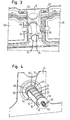
Figur 3 eine schematische Ansicht der Luftverbesserungsvorrichtung ausFigur 1 , gesehen von der Rückseite der Instrumententafel; -
Figur 4 eine schematische Rückansicht der Luftverbesserungsvorrichtung ausFigur 1 , ohne Gehäuse; -
Figur 5a, 5b und 5c schematische Ansichten der Luftverbesserungsvorrichtung ausFigur 1 in einer geschlossenen Stellung, einer Zwischenstellung und einer offenen Stellung; -
Figur 6 eine perspektivische Ansicht von Einzelteilen der Luftverbesserungsvorrichtung gemäß einer weiteren Ausführungsform; -
Figur 7 eine perspektivische Ansicht der Luftverbesserungsvorrichtung ausFigur 6 in zusammengebauten Zustand; -
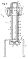
Figur 8 eine Schnittansicht der Luftverbesserungsvorrichtung ausFigur 6 ; -
Figur 9 eine weitere Schnittansicht der Luftverbesserungsvorrichtung ausFigur 6 ; und -
Figur 10a, 10b und10c Schnittansichten der Luftverbesserungsvorrichtung ausFigur 6 in verschiedenen Stellungen. - Die in
Figur 1 in schematischer Ansicht gezeigte Luftverbesserungsvorrichtung 10 für Kraftfahrzeuge umfaßt ein Gehäuse 12, das an der dem Fahrzeuginnenraum abgewandten Rückseite einer Instrumententafel 14 oder einem Anbauteil angeordnet ist. In das Gehäuse 12 ist eine Kartusche 16 zur Aufnahme eines Duftstoffträgers (hier nicht dargestellt) eingesetzt. Der Duftstoffträger ist üblicherweise ein Feststoff oder Formkörper, der mit einem Duftöl oder Parfum getränkt ist. Das Gehäuse 12 weist wenigstens eine, hier seitlich angeordnete Durchströmöffnung 18 auf, die mit einer Belüftungsöffnung 20 in der Instrumententafel 12 und dem Innenraum des Kraftfahrzeugs in Strömungsverbindung steht. Die Kartusche 16 hat eine mit der Durchströmöffnung 18 im Gehäuse 12 korrespondierende Abströmöffnung 22 und ist so im Gehäuse 12 angeordnet, daß die Kartusche von einer geschlossenen Stellung, in der die Abströmöffnung 22 vollständig vom Gehäuse 12 bedeckt ist, in eine offene Stellung beweglich ist, in der die Durchströmöffnung 18 über der Abströmöffnung 22 liegt und somit eine Abgabe des Duftstoffs von dem in der Kartusche 16 enthaltenen Duftstoffträger in den Fahrzeuginnenraum ermöglicht. - Die in
Figur 2 in Einzelteilen in perspektivischer Ansicht gezeigte Kartusche 16 hat ein zylinderförmiges Kartuschengehäuse 24, in dem die Abströmöffnungen 22 axial nebeneinander angeordnet sind. Bei der hier gezeigten Ausführungsform sind die Abströmöffnungen im wesentlichen über die Gesamtlänge der Kartusche 16 bzw. des Kartuschengehäuses 24 verteilt und durch Stege 26 voneinander getrennt. Die Stege tragen zur Stabilität des Kartuschengehäuses bei. Das Kartuschengehäuse 16 ist darüber hinaus symmetrisch aufgebaut, d. h. es sind einander radial gegenüberliegende Paare von Abströmöffnungen 22 vorhanden. Zwischen den Paaren von Abströmöffnungen 22 befindet sich jeweils ein geschlossener Wandabschnitt 23 des Kartuschengehäuses 24. Bei der bevorzugten drehbeweglichen Anordnung der Kartusche 16 im Gehäuse 12 kann somit ein einfacher Übergang von der geschlossenen Stellung der Kartusche 16 in die offene Stellung erreicht werden. - An seinem im eingebauten Zustand (
Figur 4 ) von der Instrumententafel abgewandten Ende ist das Kartuschengehäuse 24 mit einem Deckel 28 verschlossen. Die Verbindung zwischen dem Deckel 28 und dem Kartuschengehäuse 24 erfolgt bei der hier gezeigten Ausführungsform über eine Rastverbindung durch an das Ende des Kartuschengehäuses angeformt Rasthaken 30, die in entsprechende Öffnungen 32 eingreifen und den Deckel am Kartuschengehäuse 24 festlegen. Die Rastverbindung ist dabei so ausgelegt, daß der Deckel 28 für einen Austausch des in das Kartuschengehäuse 24 eingebrachten Duftstoffträgers manuell oder mittels eines Werkzeugs geöffnet werden kann. Hierdurch wird die Wiederverwertbarkeit der Kartusche 16 nach dem Verbrauch des Duftstoffträgers erreicht, da der Deckel 28 zerstörungsfrei abgenommen werden kann. - An seinem dem Deckel 28 gegenüberliegenden Ende weist das Kartuschengehäuse 24 einen angeformten zylindrischen Endabschnitt 34 auf, in den ein Längsschlitz 36 eingebracht ist. Der Endabschnitt 34 hat einen im Vergleich zum Kartuschengehäuse 24 geringeren Durchmesser. Im eingebauten Zustand der Kartusche 16 übergreift ein Kopfteil 38 den Endabschnitt 34, wobei ein im Kopfteil 38 angeordneter Vorsprung oder Zapfen in die Längsschlitze 36 am Endabschnitt 34 eingreift, so daß eine feste Verbindung zwischen Kopfteil 38 und dem Endabschnitt 34 des Kartuschengehäuses 24 besteht. Bei der hier gezeigten Ausführungsform weist der Endabschnitt 34 weiter einen Schulterabschnitt 40 auf der an einen Anschlag (hier nicht dargestellt) im Kopfteil 38 angrenzt. Auf das Kopfteil 38 ist ferner eine Verschlußkappe 42 aufgesetzt, die an ihrer Innenfläche mit hier nicht dargestellten Vorsprüngen versehen sein kann, welche in korrespondierende Aussparungen 44 an der Stirn- oder Seitenfläche des Kopfteils 38 eingreifen können und so eine bessere Kraftübertragung von der Verschlußkappe 42 auf das Kopfteil 38 bzw. das mit dem Kopfteil verbundene Kartuschengehäuse 24 ermöglichen. Alternativ dazu können das Kopfteil 38 und die Verschlußkappe 42 auch einstückig miteinander, beispielsweise als Zweikomponenten-Spritzteil, gebildet sein.
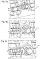
- Das Kopfteil 38 weist einen zylindrischen Abschnitt 46 und einen vom zylindrischen Abschnitt radial vorstehenden Flanschabschnitt 48 auf. Wie in
Figur 4 zu erkennen ist, ist der zylindrische Abschnitt 46 mit der darin über den Endabschnitt 34 befestigten Kartusche 16 durch eine Öffnung 50 in der Instrumententafel 14 geführt und grenzt mit zwei radial vorstehenden Befestigungspunkten 52, die an dem dem Kartuschengehäuse 24 zugewandten Ende angeformt sind, an die Rückseite der Instrumententafel an. Das Einführen der Kartusche 16 mit den Befestigungspunkten 52 am Kopfteil 38 in die Öffnung 50 der Instrumententafel 14 wird durch Aussparungen 54 am Rand der Öffnung 50 gestattet, die in Größe und Form den Befestigungspunkten 52 entsprechen. An der vorderen Seite der Instrumententafel 14 werden die Aussparungen 54 durch den an die Instrumententafel 14 angrenzenden Flanschabschnitt 48 verdeckt. - Im eingebauten Zustand wird die Kartusche 16 durch ein in das Gehäuse 12 eingebrachtes Federelement 56, beispielsweise eine Spiralfeder oder eine Blattfeder, gegen die Instrumententafel 14 mit Kraft beaufschlagt. Dadurch werden die Befestigungspunkte 52 am zylindrischen Abschnitt 46 des Kopfteils 38 gegen die Rückseite der Instrumententafel 14 gedrückt, und die Kartusche 16 wird ähnlich wie mit einem Bajonettverschluß sicher in Position gehalten. An der Rückseite der Instrumententafel 14 können zudem noch Rastpunkte 58 vorgesehen sein in welche die Befestigungspunkte 52 bei der Betätigung des Kopfteils 38 durch die Verschlußkappe 42 einrasten und somit vorbestimmte Positionen der Kartusche 16 und der Abströmöffnungen 22 definieren.
- An der einem Befestigungspunkt 52 gegenüberliegenden Stelle des Flanschabschnitts 48 im Kopfteil 38 ist darüber hinaus eine Markierung 60 in Form eines radial und/oder axial vorstehenden Vorsprungs vorgesehen, der in eine entsprechende, in die Verschlußkappe 42 eingebrachte Aussparung (hier nicht gezeigt) eingreift, deren Position mit einer Markierung 61 versehen ist. Über die Markierungen 60 bzw. 61 kann somit der Fahrzeuginsasse die Stellung der Kartusche 16 und der Abströmöffnungen 22 sicher erkennen. Beispielweise kann die nach oben zeigende Markierung 61 die geschlossene Stellung der Kartusche 16 anzeigen, in der die Abströmöffnungen 22 vollständig vom Gehäuse 12 bedeckt sind. Die offene Stellung der Kartusche 16 mit freiliegenden Abströmöffnungen 22 wird dementsprechend durch eine Drehung der Verschlußkappe um 90 Grad im Uhrzeigersinn und eine dann entsprechend nach rechts weisende Markierung 61 angezeigt.
- Zur besseren Abdichtung der Abströmöffnungen 22 gegenüber dem Fahrzeuginnenraum ist das Kartuschengehäuse 24 mit einer Dichtlippe 62 versehen, die in Längsrichtung an die Abströmöffnung 22 angrenzt und diese in der geschlossenen Stellung zuverlässig vom Fahrzeuginnenraum abdichtet, so daß keine unbeabsichtigte Abgabe von Duftstoffen aus dem in der Kartusche 16 enthaltenen Duftstoffträger erfolgt.
- Das in
Figur 3 in rückseitiger Ansicht gezeigte Gehäuse 12 weist einen hohlzylindrischen Abschnitt 64 auf, in den die Kartusche 16 drehbeweglich aufgenommen ist, sowie seitlich vom hohlzylindrischen Abschnitt 64 abstehende rohrförmige Ansatzstücke 66, die eine Strömungsverbindung zwischen den Belüftungsöffnungen 20 in der Instrumententafel 14 und den Abströmöffnungen 22 in der Kartusche 16 herstellen. Das Gehäuse hat ferner einen geschlossenen Bodenabschnitt 67, an dem sich das Federelement 56 der Kartusche 16 abstützt. Die Belüftungsöffnungen 20 sind rückseitig in bekannter Weise mit Lüftungsklappen 68 versehen, die eine regelbare Luftzufuhr zum Fahrzeuginnenraum gestatten. Das Gehäuse 12 kann in die Instrumententafel 14 oder ein entsprechendes Anbauteil integriert oder vorzugsweise als separates Bauteil ausgeführt sein. - Im Folgenden soll die Funktionsweise der erfindungsgemäßen Luftverbesserungsvorrichtung 10 anhand der
Figuren 5a bis 5c näher erläutert werden. -
Figur 5a zeigt die Luftverbesserungsvorrichtung 10 in der geschlossenen Stellung. Die in das Gehäuse 12 eingesetzte Kartusche 16 mit dem darin enthaltenen Duftstoffträger ist so angeordnet, daß die Abströmöffnungen 22 vollständig vom Gehäuse 12 bedeckt sind. Die Durchströmöffnungen 18 im Gehäuse 12 sind hier von dem geschlossenen Wandbereich 23 des Kartuschengehäuses 24 verdeckt. Die sich in axialer Richtung erstreckenden Dichtlippen 62 dichten die Abströmöffnungen 22 bzw. die Durchströmöffnungen 18 vollständig vom Fahrzeuginnenraum ab, so daß keine Abgabe von Duftstoffen in den Fahrzeuginnenraum erfolgen kann. Die an der Kappe 42 angebrachte Markierung 62 zeigt inFigur 5a nach oben und läßt somit die geschlossene Stellung der Kartusche 16 erkennen. - Durch eine Drehung der Kappe 42 um ca. 20° nach rechts wird die in
Figur 5b erreichte Zwischenstellung erreicht, bei der die Abströmöffnungen 22 noch teilweise vom Gehäuse 12 verdeckt werden. Da in dieser Stellung ein geringerer Strömungsquerschnitt zur Verfügung steht, ist die Abgabe von Duftstoffen in den Fahrzeuginnenraum reduziert. - Bei der in
Figur 5c gezeigten offenen Stellung der Kartusche 16 liegt die Durchströmöffnung 18 vollständig über den Abströmöffnungen 22. In dieser Stellung ist der größtmögliche Strömungsquerschnitt erreicht und die Abgabe des Duftstoffs in den Fahrzeuginnenraum erfolgt mit größter Intensität. - Eine weitere Ausführungsform der erfindungsgemäßen Luftverbesserungsvorrichtung 10 ist in den
Figuren 6 bis 9 dargestellt. Bauteile, welche die gleiche Funktion wie in der oben beschriebenen ersten Ausführungsform der erfindungsgemäßen Luftverbesserungsvorrichtung 10 erfüllen, sind mit den gleichen Bezugszeichen versehen. Insoweit wird auf die obige Beschreibung verwiesen. - Bei der hier dargestellten Ausführungsform der erfindungsgemäßen Luftverbesserungsvorrichtung 10 umfaßt die Kartusche 16 das zylinderförmige Kartuschengehäuse 24 sowie zusätzlich eine Aufnahmehülse 70 für das Kartuschengehäuse 24. Die Aufnahmehülse 70 ist an ihrem Außenumfang mit einer Längsrippe 72 versehen, die im eingebauten Zustand in eine korrespondierende Nut 74 im Gehäuse 12 eingreift und die Aufnahmehülse 70 unbeweglich im Gehäuse 12 fixiert. Bevorzugt sind an der Aufnahmehülse 70 zwei einander gegenüberliegende Längsrippen 72 und im Gehäuse 12 zwei entsprechende Nuten 74 ausgebildet. Die Aufnahmehülse 70 umfaßt ferner wenigstens eine sich in Längsrichtung erstreckende Durchtrittsöffnung 76, die durch Stege 78 in mehrere Öffnungsabschnitte unterteilt sein kann. Vorzugsweise sind in der Aufnahmehülse 70 zwei einander gegenüberliegende Durchtrittsöffnungen 76 ausgebildet, die mit den Abströmöffnungen 22 im Kartuschengehäuse 24 korrespondieren und im eingebauten Zustand außerdem fluchtend zur Durchströmöffnung 18 im Gehäuse 12 angeordnet sind.
- Das zylinderförmige Kartuschengehäuse 24 ist drehbeweglich in der Aufnahmehülse 70 angeordnet und kann von der geschlossenen Stellung, in der die Abströmöffnungen 22 des Kartuschengehäuses 24 vollständig, hier von einem durchgehenden Wandabschnitt der Aufnahmehülse 70, bedeckt sind, in eine offene Stellung bewegt werden, in der die Durchtrittsöffnung 76 über den Abströmöffnungen 22 liegt und damit die Abgabe eines Duftstoffs von dem im Kartuschengehäuse 24 aufgenommenen Duftstoffträger 79 (
Figur 10 ) in den Fahrzeuginnenraum ermöglicht. Zur Begrenzung der Drehbewegung des Kartuschengehäuses 24 in der Aufnahmehülse 70 und zur Definition der offenen Stellung und der geschlossenen Stellung kann die Aufnahmehülse 70 schließlich an einem ihrer freien Enden einen Anschlag 80 aufweisen, der mit einer nahe des Endabschnitts 34 am Kartuschengehäuse 24 angeordneten, radial vorstehenden Nase 82 zusammenwirkt. - In den
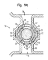
Figuren 10a bis 10c ist die Funktionsweise der Luftverbesserungsvorrichtung 10 gemäß der hier beschriebenen Ausführungsform dargestellt. Die Parfumkartusche 16 wird in ihrer geschlossenen Stellung durch eine Öffnung in der Instrumententafel (hier nicht dargestellt) in das Gehäuse 12 eingesetzt. In der geschlossenen Stellung sind die Abströmöffnungen 22 von den durchgehenden Wandabschnitten der Aufnahmehülse 70 vollständig bedeckt. Des weiteren liegt die Wand 23 des Kartuschengehäuses 24 vor den Durchtrittsöffnungen 76 in der Aufnahmehülse 70. Außerdem ist das Kartuschengehäuse 24 gegenüber der Aufnahmehülse durch die Dichtlippen 62 so abgedichtet, daß kein Duftstoff aus dem im Kartuschengehäuse 64 angeordneten Duftstoffträger über die Durchströmöffnungen 18 im Gehäuse 12 in das Fahrzeuginnere gelangen kann. - Durch eine geringfügige Drehung in Richtung des Pfeils A (
Figur 10b ) wird der Befestigungspunkt 52 (Figur 9 ) rückseitig in Anlage an die Instrumententafel 14 gebracht und die Kartusche 16 wie bei einem Bajonettverschluß verrastet. Auch in dieser Position befindet sich die Kartusche 16 noch in der geschlossenen Stellung. Durch Drücken und Drehen des für den Fahrzeuginsassen zugänglichen, aus Kopfteil 38 und Verschlußkappe 42 gebildeten Bedienknopfes kann die Kartusche 16 so nach einem Verbrauch des Duftstoffes leicht wieder entfernt und durch eine neue Kartusche 16 ersetzt werden. - Durch eine weitere Drehung in Richtung des Pfeils A (
Figur 10b ) werden schließlich die Abströmöffnungen 22 freigegeben (Figur 10c ) und der Duftstoff kann von dem Duftstoffträger 79 aus den Abströmöffnungen 22 und der darüber liegenden Durchtrittsöffnung 76 über die Durchströmöffnung 18 im Gehäuse 12 in das Fahrzeuginnere abgegeben werden. Die Endposition dieser offenen Stellung der Kartusche 16 kann durch den Anschlag 80 an der Aufnahmehülse 70 und die Nase 82 am Kartuschengehäuse 24 (Figur 9 ) festgelegt werden. Über Zwischenstellungen zwischen der geschlossenen und der offenen Stellung läßt sich die in den Fahrzeuginnenraum abgegebene Menge des Duftstoffs nach den Wünschen des Fahrzeuginsassen regulieren.
Claims (34)
- Luftverbesserungsvorrichtung (10) zur Verwendung in Kraftfahrzeugen, mit einem Gehäuse (12) und einer in das Gehäuse (16) eingesetzten Kartusche (16) zur Aufnahme eines Duftstoffträgers (79), wobei das Gehäuse (12) rückseitig an einer Instrumententafel (14) des Kraftfahrzeugs angeordnet ist und wenigstens eine Durchströmöffnung (18) aufweist, die mit Belüftungsöffnungen (20) in der Instrumententafel (14) in Strömungsverbindung steht, und wobei die Kartusche (16) wenigstens eine mit der Durchströmöffnung (18) im Gehäuse (12) korrespondierende Abströmöffnung (22) aufweist, wobei die Luftverbesserungsvorrichtung dadurch gekennzeichnet ist, dass die Kartusche derart im Gehäuse (12) angeordnet ist, daß die Kartusche (16) von einer geschlossenen Stellung, in der die Abströmöffnung (22) vollständig bedeckt ist, in eine offene Stellung beweglich ist, in der die Durchströmöffnung (18) über der Abströmöffnung (22) liegt.
- Luftverbesserungsvorrichtung (10) nach Anspruch 1, dadurch gekennzeichnet, daß die Kartusche (16) im Gehäuse (12) drehbeweglich angeordnet ist.
- Luftverbesserungsvorrichtung (10) nach Anspruch 1 oder 2, dadurch gekennzeichnet, daß die Kartusche (16) ein zylinderförmiges Kartuschengehäuse (24) umfaßt.
- Luftverbesserungsvorrichtung (10) nach einem der Ansprüche 1 bis 3, dadurch gekennzeichnet, daß die Kartusche (16) radial gegenüberliegende, sich in Längsrichtung der Kartusche (16) erstreckende Abströmöffnungen (22) aufweist.
- Luftverbesserungsvorrichtung (10) nach einem der Ansprüche 1 bis 4, dadurch gekennzeichnet, daß die Abströmöffnungen (22) im wesentlichen über die Gesamtlänge der Kartusche (16) angeordnet und durch Stege (26) voneinander getrennt sind.
- Luftverbesserungsvorrichtung (10) nach einem der Ansprüche 1 bis 5, dadurch gekennzeichnet, daß das von der Instrumententafel (14) abgewandte Ende der Kartusche (16) einen Deckel (28) umfaßt.
- Luftverbesserungsvorrichtung (10) nach Anspruch 6, dadurch gekennzeichnet, daß der Deckel (28) zerstörungsfrei abnehmbar ist.
- Luftverbesserungsvorrichtung (10) nach einem der Ansprüche 1 bis 7, dadurch gekennzeichnet, daß die Kartusche (16) einen Endabschnitt (34) aufweist, der fest mit einem Kopfteil (38) verbunden ist.
- Luftverbesserungsvorrichtung (10) nach Anspruch 8, dadurch gekennzeichnet, daß der Endabschnitt (34) der Kartusche (16) eine Ausnehmung (36) aufweist, in die ein Vorsprung im Kopfteil (38) eingreift, so daß das Kopfteil (38) auf den Endabschnitt (34) aufgeklemmt ist.
- Luftverbesserungsvorrichtung (10) nach Anspruch 8 oder 9, dadurch gekennzeichnet, daß das Kopfteil (38) einen zylindrischen Abschnitt (46) und einen radial vom zylindrischen Abschnitt (46) vorstehenden Flanschabschnitt (48) aufweist und mit dem zylindrischen Abschnitt (46) durch eine Öffnung (50) in der Instrumententafel (14) geführt ist, so daß der Flanschabschnitt (48) vorderseitig an die Instrumententafel (14) angrenzt.
- Luftverbesserungsvorrichtung (10) nach Anspruch 10, dadurch gekennzeichnet, daß der zylindrische Abschnitt (46) an seinem der Kartusche (16) zugewandten Ende wenigstens einen radial vorstehenden Befestigungspunkt (52) aufweist, der von einem auf die Kartusche (16) wirkenden Federelement (56) gegen die Rückseite der Instrumententafel (16) gedrückt wird.
- Luftverbesserungsvorrichtung (10) nach Anspruch 11, dadurch gekennzeichnet, daß auf einer dem Befestigungspunkt (52) gegenüberliegenden Stelle des Flanschabschnitts (48) eine Markierung (60) angeordnet ist.
- Luftverbesserungsvorrichtung (10) nach einem der Ansprüche 10 bis 12, dadurch gekennzeichnet, daß das der zylindrische Abschnitt (46) an seinem der Kartusche (16) abgewandten Ende mit einer Kappe (42) versehen ist.
- Luftverbesserungsvorrichtung (10) nach einem der Ansprüche 1 bis 13, dadurch gekennzeichnet, daß das Gehäuse (12) eine stirnseitige Öffnung umfaßt, die mit einer Öffnung (50) in der Instrumententafel (14) korrespondiert und in die die Kartusche (16) auswechselbar eingesetzt ist.
- Luftverbesserungsvorrichtung (10) nach einem der Ansprüche 1 bis 14, dadurch gekennzeichnet, daß die Kartusche (16) außenseitig angeordnete Dichtlippen (62) umfaßt, die die Abströmöffnungen (22) in der geschlossenen Stellung gegen die Durchströmöffnung (18) im Gehäuse (12) abdichten.
- Luftverbesserungsvorrichtung (10) nach einem der Ansprüche 1 bis 15, dadurch gekennzeichnet, daß die Kartusche (16) ein zylinderförmiges Kartuschengehäuse (24) und eine Aufnahmehülse (70) für das Kartuschengehäuse (24) umfaßt, wobei die Aufnahmehülse (70) gegenüber dem Gehäuse (12) unbeweglich angeordnet und das Kartuschengehäuse (24) in der Aufnahmehülse (70) drehbeweglich angeordnet ist.
- Luftverbesserungsvorrichtung (10) nach Anspruch 16, dadurch gekennzeichnet, daß die Aufnahmehülse (70) an ihrem Außenumfang wenigstens eine Längsrippe (72) aufweist, die in eine korrespondierende Nut (74) im Gehäuse (12) eingreift und die Aufnahmehülse (70) im Gehäuse (12) fixiert.
- Luftverbesserungsvorrichtung (10) nach Anspruch 16 oder 17, dadurch gekennzeichnet, daß die Aufnahmehülse (70) wenigstens eine in Längsrichtung angeordnete Durchtrittsöffnung (76) aufweist, die fluchtend mit der Durchströmöffnung (18) im Gehäuse (12) angeordnet ist.
- Luftverbesserungsvorrichtung (10) nach Anspruch 18, dadurch gekennzeichnet, daß die Durchtrittsöffnung (76) durch Stege (78) unterteilt ist.
- Luftverbesserungsvorrichtung (10) nach einem der Ansprüche 16 bis 19, dadurch gekennzeichnet, daß die Aufnahmehülse (70) an ihrem der Instrumententafel (14) zugewandten Ende einen Anschlag (80) zur Begrenzung der Drehbewegung des Kartuschengehäuses (24) aufweist.
- Kartusche (16) zur Verwendung in einer Luftverbesserungsvorrichtung (10) gemäß einem der vorhergehenden Ansprüche, mit einem zylinderförmigen Kartuschengehäuse (24) zur Aufnahme eines Duftstoffträgers und in Längsrichtung des Kartuschengehäuses (24) angeordneten Abströmöffnungen (22), dadurch gekennzeichnet, daß die Abströmöffnungen (22) im wesentlichen über die Gesamtlänge der Kartusche (16) angeordnet und durch Stege (26) voneinander getrennt sind.
- Kartusche (16) nach Anspruch 21, dadurch gekennzeichnet, daß ein freies Ende des Kartuschengehäuses (24) mit einem Deckel (28) verschlossen ist.
- Kartusche (16) nach Anspruch 22, dadurch gekennzeichnet, daß der Deckel (28) zerstörungsfrei abnehmbar ist.
- Kartusche (16) nach Anspruch 22 oder 23, dadurch gekennzeichnet, daß das Kartuschengehäuse (24) an seinem dem Deckel (28) gegenüberliegenden Ende einen angeformten Endabschnitt (34) aufweist, der fest mit einem den Endabschnitt (34) übergreifenden Kopfteil (38) verbunden ist.
- Kartusche (16) nach Anspruch 24, dadurch gekennzeichnet, daß der Endabschnitt (34) des Kartuschengehäuses (24) eine Ausnehmung (36) aufweist, in die ein Vorsprung im Kopfteil (38) eingreift, so daß das Kopfteil (38) auf den Endabschnitt (34) aufgeklemmt ist.
- Kartusche (16) nach Anspruch 24 oder 25, dadurch gekennzeichnet, daß das Kopfteil (38) einen zylindrischen Abschnitt (46) und einen radial vom zylindrischen Abschnitt (46) vorstehenden Flanschabschnitt (48) aufweist.
- Kartusche (16) nach Anspruch 26, dadurch gekennzeichnet, daß der zylindrische Abschnitt (46) an seinem dem Kartuschengehäuse (24) zugewandten Ende wenigstens einen radial vorstehenden Befestigungspunkt (52) zur Fixierung der Kartusche (16) aufweist.
- Kartusche (16) nach Anspruch 27, dadurch gekennzeichnet, daß auf einer dem Befestigungspunkt (52) gegenüberliegenden Stelle des Flanschabschnitts (48) eine Markierung (60) angeordnet ist.
- Kartusche (16) nach einem der Ansprüche 26 bis 28, dadurch gekennzeichnet, daß der zylindrische Abschnitt (46) an seinem dem Kartuschengehäuse (24) abgewandten Ende mit einer Kappe (42) versehen ist.
- Kartusche (16) nach einem der Ansprüche 21 bis 29, dadurch gekennzeichnet, daß das Kartuschengehäuse (24) außenseitig angeordnete und in axialer Richtung verlaufende Dichtlippen (62) umfaßt.
- Kartusche (16) nach einem der Ansprüche 21 bis 30, dadurch gekennzeichnet, daß die Kartusche (16) ferner eine Aufnahmehülse (70) für das Kartuschengehäuse (24) mit wenigstens einer in Längsrichtung angeordneten Durchtrittsöffnung (76) umfaßt, wobei das Kartuschengehäuse (24) in der Aufnahmehülse (70) drehbeweglich angeordnet und von einer geschlossenen Stellung, in der die Abströmöffnungen (22) vollständig von der Aufnahmehülse (70) bedeckt sind, in eine offene Stellung beweglich ist, in der die Durchtrittsöffnung (76) über den Abströmöffnungen (22) liegt.
- Kartusche (16) nach Anspruch 31, dadurch gekennzeichnet, daß die Aufnahmehülse (70) an ihrem Außenumfang wenigstens eine Längsrippe (72) zur Fixierung der Aufnahmehülse (70) aufweist.
- Kartusche (16) nach Anspruch 31 oder 32, dadurch gekennzeichnet, daß die Durchtrittsöffnung (76) durch Stege (78) unterteilt ist.
- Kartusche (16) nach einem der Ansprüche 31 bis 33, dadurch gekennzeichnet, daß die Aufnahmehülse (70) an einem ihrer freien Enden einen Anschlag (80) zur Begrenzung der Drehbewegung des Kartuschengehäuses (24) aufweist.
Priority Applications (1)
| Application Number | Priority Date | Filing Date | Title |
|---|---|---|---|
| PL05011917T PL1609643T3 (pl) | 2004-06-25 | 2005-06-02 | Urządzenie do polepszania powietrza, do stosowania w samochodach, i wkład do urządzenia do polepszania powietrza |
Applications Claiming Priority (2)
| Application Number | Priority Date | Filing Date | Title |
|---|---|---|---|
| DE202004010015U DE202004010015U1 (de) | 2004-06-25 | 2004-06-25 | Luftverbesserungsvorrichtung zur Verwendung in Kraftfahrzeugen und Kartusche für die Luftverbesserungsvorrichtung |
| DE202004010015U | 2004-06-25 |
Publications (3)
| Publication Number | Publication Date |
|---|---|
| EP1609643A2 EP1609643A2 (de) | 2005-12-28 |
| EP1609643A3 EP1609643A3 (de) | 2006-07-12 |
| EP1609643B1 true EP1609643B1 (de) | 2010-03-03 |
Family
ID=33395315
Family Applications (1)
| Application Number | Title | Priority Date | Filing Date |
|---|---|---|---|
| EP05011917A Expired - Lifetime EP1609643B1 (de) | 2004-06-25 | 2005-06-02 | Luftverbesserungsvorrichtung zur Verwendung in Kraftfahrzeugen und Kartusche für die Luftverbesserungsvorrichtung |
Country Status (6)
| Country | Link |
|---|---|
| EP (1) | EP1609643B1 (de) |
| AT (1) | ATE459498T1 (de) |
| DE (2) | DE202004010015U1 (de) |
| ES (1) | ES2341111T3 (de) |
| PL (1) | PL1609643T3 (de) |
| RU (1) | RU2383446C2 (de) |
Cited By (1)
| Publication number | Priority date | Publication date | Assignee | Title |
|---|---|---|---|---|
| DE102020201192A1 (de) | 2020-01-31 | 2021-08-05 | Mahle International Gmbh | Selbstschließende Duftkartusche und Bedufter |
Families Citing this family (13)
| Publication number | Priority date | Publication date | Assignee | Title |
|---|---|---|---|---|
| DE102004017067A1 (de) * | 2004-04-07 | 2005-10-27 | Daimlerchrysler Ag | Belüftungseinrichtung für ein Kraftfahrzeug |
| ES2263354B1 (es) * | 2004-11-02 | 2007-11-01 | Maier, S. Coop. | Sistema ambientador integrado en el aireador de un vehiculo. |
| JP4531571B2 (ja) * | 2005-01-04 | 2010-08-25 | 株式会社ヴァレオサーマルシステムズ | 抗菌剤を封入した容器の固定機構及びその容器 |
| FR2887616B1 (fr) * | 2005-06-22 | 2013-03-01 | Valeo Systemes Thermiques | Dispositif de traitement antimicrobien par diffusion d'un agent traitant volatil pour une installation de ventilation, de chauffage et/ou de climatisation, d'un vehicule notamment |
| DE102005041985A1 (de) | 2005-09-05 | 2007-03-22 | GM Global Technology Operations, Inc., Detroit | Dosierbares Duftstoffgerät zur Anwendung in einem Kraftfahrzeug |
| FR2904227B1 (fr) * | 2006-07-27 | 2008-09-05 | Bourbon Automobile Soc Par Act | Cartouche de diffusion de parfum pour aerateur a parfum et procede de fabrication de cette cartouche |
| FR2918317B1 (fr) * | 2007-07-02 | 2014-06-27 | Valeo Systemes Thermiques | Dispositif de diffusion d'agent volatil muni d'un bouchon pour vehicule automobile |
| FR2918318B1 (fr) * | 2007-07-02 | 2009-10-23 | Valeo Systemes Thermiques | Dispositif de diffusion d'agent volatil muni d'un moyen d'extraction de cartouche |
| EP2269850B1 (de) * | 2009-07-02 | 2014-10-15 | Behr GmbH & Co. KG | Beduftungssystem |
| JP5574777B2 (ja) * | 2010-03-26 | 2014-08-20 | 富士重工業株式会社 | 効能成分供給装置 |
| FR3026306B1 (fr) * | 2014-09-30 | 2016-10-21 | Valeo Systemes Thermiques | Systeme de verrouillage de cartouche amovible dans un boitier |
| FR3026307B1 (fr) * | 2014-09-30 | 2017-11-24 | Valeo Systemes Thermiques | Dispositif de diffusion et cartouche amovible pour ledit dispositif |
| CN111216519B (zh) * | 2018-11-26 | 2023-08-04 | 蔚来(安徽)控股有限公司 | 车载香氛装置、车载香氛系统、车载香氛更换方法及车辆 |
Family Cites Families (7)
| Publication number | Priority date | Publication date | Assignee | Title |
|---|---|---|---|---|
| JPS63222919A (ja) * | 1987-03-13 | 1988-09-16 | Matsushita Electric Works Ltd | 芳香発生装置 |
| US5314669A (en) * | 1992-06-15 | 1994-05-24 | Randy Hamilton | Method and apparatus for dispensing a scent into the air |
| RU2092190C1 (ru) * | 1995-07-11 | 1997-10-10 | Павел Иванович Козьменко | Устройство для ароматизации воздуха в помещении |
| KR100382155B1 (ko) * | 2001-04-12 | 2003-05-09 | 조성호 | 수납식 송풍그릴 프레임을 갖는 자동차용 송풍구 |
| FR2833534B1 (fr) * | 2001-12-13 | 2004-06-18 | Valeo Climatisation | Dispositif d'odorisation de l'habitacle d'un vehicule automobile |
| FR2833887B1 (fr) * | 2001-12-20 | 2004-02-27 | Valeo Climatisation | Dispositif d'odorisation de l'habitacle d'un vehicule automobile |
| FR2848915B1 (fr) | 2002-12-20 | 2005-03-18 | Peugeot Citroen Automobiles Sa | Dispositif de diffusion d'au moins un parfum dans un habitacle d'un vehicule automobile. |
-
2004
- 2004-06-25 DE DE202004010015U patent/DE202004010015U1/de not_active Expired - Lifetime
-
2005
- 2005-06-02 PL PL05011917T patent/PL1609643T3/pl unknown
- 2005-06-02 AT AT05011917T patent/ATE459498T1/de not_active IP Right Cessation
- 2005-06-02 EP EP05011917A patent/EP1609643B1/de not_active Expired - Lifetime
- 2005-06-02 ES ES05011917T patent/ES2341111T3/es not_active Expired - Lifetime
- 2005-06-02 DE DE502005009119T patent/DE502005009119D1/de not_active Expired - Lifetime
- 2005-06-24 RU RU2005119749/11A patent/RU2383446C2/ru not_active IP Right Cessation
Cited By (1)
| Publication number | Priority date | Publication date | Assignee | Title |
|---|---|---|---|---|
| DE102020201192A1 (de) | 2020-01-31 | 2021-08-05 | Mahle International Gmbh | Selbstschließende Duftkartusche und Bedufter |
Also Published As
| Publication number | Publication date |
|---|---|
| EP1609643A2 (de) | 2005-12-28 |
| RU2383446C2 (ru) | 2010-03-10 |
| DE502005009119D1 (de) | 2010-04-15 |
| EP1609643A3 (de) | 2006-07-12 |
| PL1609643T3 (pl) | 2010-08-31 |
| DE202004010015U1 (de) | 2004-10-28 |
| RU2005119749A (ru) | 2006-12-27 |
| ES2341111T3 (es) | 2010-06-15 |
| ATE459498T1 (de) | 2010-03-15 |
Similar Documents
| Publication | Publication Date | Title |
|---|---|---|
| EP1609643B1 (de) | Luftverbesserungsvorrichtung zur Verwendung in Kraftfahrzeugen und Kartusche für die Luftverbesserungsvorrichtung | |
| EP2164531B1 (de) | Beduftungsvorrichtung, insbesondere für ein kraftfahrzeug | |
| DE69101873T2 (de) | Flüssigkeitsspender mit Abgabevorrichtung zur Erzeugung eines Ansaugluftstroms. | |
| DE60201488T2 (de) | Duftdiffusionsmittel für einen Fahrzeuginnenraum | |
| EP2218518B1 (de) | Mehrkomponentenkartusche zur einmaligen Verwendung | |
| EP2747898B1 (de) | System aus kartuschen und mischern | |
| WO2012129709A1 (de) | Beduftungsvorrichtung für ein fahrzeug | |
| DE102018002101A1 (de) | Abgabespeicher und Spender | |
| WO1988003881A1 (fr) | Dispositif pour vaporiser un agent dans le milieu ambiant pour le conditionner | |
| DE69915783T2 (de) | Spender | |
| EP3741396A1 (de) | Mehrzweckbehälter zum bereitstellen von tüchern mit einer lufterfrischungsfunktion | |
| DE102005025409A1 (de) | Luftverbesserungsvorrichtung zur Verwendung in Kraftfahrzeugen und Kartusche für die Luftverbesserungsvorrichtung | |
| EP4144384B1 (de) | Beduftungsvorrichtung für ein fahrzeug | |
| EP1533125B3 (de) | Tintenpatrone, Tintenpatroneneinheit sowie Tintenstrahldruckkopf | |
| WO2010145889A1 (de) | Mehrkomponentenkartusche zur einmaligen verwendung | |
| DE20212778U1 (de) | Luftdüse mit Duftspender | |
| DE19847651A1 (de) | Anordnung eines Duftspenders im Luftstrom einer Belüftungs- oder Klimaanlage | |
| EP4144385B1 (de) | Beduftungsvorrichtung für ein fahrzeug | |
| DE202004006316U1 (de) | Lüftungsdüse mit Duftspender | |
| WO2005100063A1 (de) | Belüftungseinrichtung für ein kraftfahrzeug | |
| DE102013212530A1 (de) | Beduftungsvorrichtung | |
| DE102005025755A1 (de) | Vorrichtung zur Verteilung von Geruchsstoffen | |
| EP4144383B1 (de) | Beduftungsvorrichtung für ein fahrzeug | |
| EP1759899B1 (de) | Dosierbares Duftstoffgerät zur Anwendung in einem Kraftfahrzeug | |
| DE102015205304A1 (de) | Beduftungsvorrichtung |
Legal Events
| Date | Code | Title | Description |
|---|---|---|---|
| PUAI | Public reference made under article 153(3) epc to a published international application that has entered the european phase |
Free format text: ORIGINAL CODE: 0009012 |
|
| AK | Designated contracting states |
Kind code of ref document: A2 Designated state(s): AT BE BG CH CY CZ DE DK EE ES FI FR GB GR HU IE IS IT LI LT LU MC NL PL PT RO SE SI SK TR |
|
| AX | Request for extension of the european patent |
Extension state: AL BA HR LV MK YU |
|
| PUAL | Search report despatched |
Free format text: ORIGINAL CODE: 0009013 |
|
| AK | Designated contracting states |
Kind code of ref document: A3 Designated state(s): AT BE BG CH CY CZ DE DK EE ES FI FR GB GR HU IE IS IT LI LT LU MC NL PL PT RO SE SI SK TR |
|
| AX | Request for extension of the european patent |
Extension state: AL BA HR LV MK YU |
|
| 17P | Request for examination filed |
Effective date: 20061107 |
|
| AKX | Designation fees paid |
Designated state(s): AT BE BG CH CY CZ DE DK EE ES FI FR GB GR HU IE IS IT LI LT LU MC NL PL PT RO SE SI SK TR |
|
| RAP1 | Party data changed (applicant data changed or rights of an application transferred) |
Owner name: TRW AUTOMOTIVE ELECTRONICS & COMPONENTS GMBH |
|
| 17Q | First examination report despatched |
Effective date: 20080428 |
|
| GRAP | Despatch of communication of intention to grant a patent |
Free format text: ORIGINAL CODE: EPIDOSNIGR1 |
|
| GRAS | Grant fee paid |
Free format text: ORIGINAL CODE: EPIDOSNIGR3 |
|
| GRAA | (expected) grant |
Free format text: ORIGINAL CODE: 0009210 |
|
| AK | Designated contracting states |
Kind code of ref document: B1 Designated state(s): AT BE BG CH CY CZ DE DK EE ES FI FR GB GR HU IE IS IT LI LT LU MC NL PL PT RO SE SI SK TR |
|
| REG | Reference to a national code |
Ref country code: GB Ref legal event code: FG4D Free format text: NOT ENGLISH |
|
| REG | Reference to a national code |
Ref country code: CH Ref legal event code: EP |
|
| REG | Reference to a national code |
Ref country code: IE Ref legal event code: FG4D |
|
| REF | Corresponds to: |
Ref document number: 502005009119 Country of ref document: DE Date of ref document: 20100415 Kind code of ref document: P |
|
| REG | Reference to a national code |
Ref country code: SE Ref legal event code: TRGR Ref country code: ES Ref legal event code: FG2A Ref document number: 2341111 Country of ref document: ES Kind code of ref document: T3 |
|
| REG | Reference to a national code |
Ref country code: NL Ref legal event code: VDEP Effective date: 20100303 |
|
| REG | Reference to a national code |
Ref country code: HU Ref legal event code: AG4A Ref document number: E007637 Country of ref document: HU |
|
| PG25 | Lapsed in a contracting state [announced via postgrant information from national office to epo] |
Ref country code: LT Free format text: LAPSE BECAUSE OF FAILURE TO SUBMIT A TRANSLATION OF THE DESCRIPTION OR TO PAY THE FEE WITHIN THE PRESCRIBED TIME-LIMIT Effective date: 20100303 |
|
| LTIE | Lt: invalidation of european patent or patent extension |
Effective date: 20100303 |
|
| PG25 | Lapsed in a contracting state [announced via postgrant information from national office to epo] |
Ref country code: SI Free format text: LAPSE BECAUSE OF FAILURE TO SUBMIT A TRANSLATION OF THE DESCRIPTION OR TO PAY THE FEE WITHIN THE PRESCRIBED TIME-LIMIT Effective date: 20100303 Ref country code: FI Free format text: LAPSE BECAUSE OF FAILURE TO SUBMIT A TRANSLATION OF THE DESCRIPTION OR TO PAY THE FEE WITHIN THE PRESCRIBED TIME-LIMIT Effective date: 20100303 |
|
| REG | Reference to a national code |
Ref country code: PL Ref legal event code: T3 |
|
| REG | Reference to a national code |
Ref country code: IE Ref legal event code: FD4D |
|
| PG25 | Lapsed in a contracting state [announced via postgrant information from national office to epo] |
Ref country code: RO Free format text: LAPSE BECAUSE OF FAILURE TO SUBMIT A TRANSLATION OF THE DESCRIPTION OR TO PAY THE FEE WITHIN THE PRESCRIBED TIME-LIMIT Effective date: 20100303 Ref country code: CY Free format text: LAPSE BECAUSE OF FAILURE TO SUBMIT A TRANSLATION OF THE DESCRIPTION OR TO PAY THE FEE WITHIN THE PRESCRIBED TIME-LIMIT Effective date: 20100303 Ref country code: EE Free format text: LAPSE BECAUSE OF FAILURE TO SUBMIT A TRANSLATION OF THE DESCRIPTION OR TO PAY THE FEE WITHIN THE PRESCRIBED TIME-LIMIT Effective date: 20100303 Ref country code: GR Free format text: LAPSE BECAUSE OF FAILURE TO SUBMIT A TRANSLATION OF THE DESCRIPTION OR TO PAY THE FEE WITHIN THE PRESCRIBED TIME-LIMIT Effective date: 20100604 Ref country code: IE Free format text: LAPSE BECAUSE OF FAILURE TO SUBMIT A TRANSLATION OF THE DESCRIPTION OR TO PAY THE FEE WITHIN THE PRESCRIBED TIME-LIMIT Effective date: 20100303 Ref country code: NL Free format text: LAPSE BECAUSE OF FAILURE TO SUBMIT A TRANSLATION OF THE DESCRIPTION OR TO PAY THE FEE WITHIN THE PRESCRIBED TIME-LIMIT Effective date: 20100303 |
|
| PG25 | Lapsed in a contracting state [announced via postgrant information from national office to epo] |
Ref country code: SK Free format text: LAPSE BECAUSE OF FAILURE TO SUBMIT A TRANSLATION OF THE DESCRIPTION OR TO PAY THE FEE WITHIN THE PRESCRIBED TIME-LIMIT Effective date: 20100303 Ref country code: IS Free format text: LAPSE BECAUSE OF FAILURE TO SUBMIT A TRANSLATION OF THE DESCRIPTION OR TO PAY THE FEE WITHIN THE PRESCRIBED TIME-LIMIT Effective date: 20100703 Ref country code: BG Free format text: LAPSE BECAUSE OF FAILURE TO SUBMIT A TRANSLATION OF THE DESCRIPTION OR TO PAY THE FEE WITHIN THE PRESCRIBED TIME-LIMIT Effective date: 20100603 |
|
| BERE | Be: lapsed |
Owner name: TRW AUTOMOTIVE ELECTRONICS & COMPONENTS G.M.B.H. Effective date: 20100630 |
|
| PLBE | No opposition filed within time limit |
Free format text: ORIGINAL CODE: 0009261 |
|
| STAA | Information on the status of an ep patent application or granted ep patent |
Free format text: STATUS: NO OPPOSITION FILED WITHIN TIME LIMIT |
|
| PG25 | Lapsed in a contracting state [announced via postgrant information from national office to epo] |
Ref country code: PT Free format text: LAPSE BECAUSE OF FAILURE TO SUBMIT A TRANSLATION OF THE DESCRIPTION OR TO PAY THE FEE WITHIN THE PRESCRIBED TIME-LIMIT Effective date: 20100705 Ref country code: MC Free format text: LAPSE BECAUSE OF NON-PAYMENT OF DUE FEES Effective date: 20100630 Ref country code: DK Free format text: LAPSE BECAUSE OF FAILURE TO SUBMIT A TRANSLATION OF THE DESCRIPTION OR TO PAY THE FEE WITHIN THE PRESCRIBED TIME-LIMIT Effective date: 20100303 |
|
| REG | Reference to a national code |
Ref country code: CH Ref legal event code: PL |
|
| 26N | No opposition filed |
Effective date: 20101206 |
|
| PG25 | Lapsed in a contracting state [announced via postgrant information from national office to epo] |
Ref country code: LI Free format text: LAPSE BECAUSE OF NON-PAYMENT OF DUE FEES Effective date: 20100630 Ref country code: CH Free format text: LAPSE BECAUSE OF NON-PAYMENT OF DUE FEES Effective date: 20100630 |
|
| PG25 | Lapsed in a contracting state [announced via postgrant information from national office to epo] |
Ref country code: BE Free format text: LAPSE BECAUSE OF NON-PAYMENT OF DUE FEES Effective date: 20100630 |
|
| PGFP | Annual fee paid to national office [announced via postgrant information from national office to epo] |
Ref country code: SE Payment date: 20110629 Year of fee payment: 7 |
|
| PG25 | Lapsed in a contracting state [announced via postgrant information from national office to epo] |
Ref country code: AT Free format text: LAPSE BECAUSE OF NON-PAYMENT OF DUE FEES Effective date: 20100602 |
|
| PG25 | Lapsed in a contracting state [announced via postgrant information from national office to epo] |
Ref country code: LU Free format text: LAPSE BECAUSE OF NON-PAYMENT OF DUE FEES Effective date: 20100602 |
|
| PG25 | Lapsed in a contracting state [announced via postgrant information from national office to epo] |
Ref country code: TR Free format text: LAPSE BECAUSE OF FAILURE TO SUBMIT A TRANSLATION OF THE DESCRIPTION OR TO PAY THE FEE WITHIN THE PRESCRIBED TIME-LIMIT Effective date: 20100303 |
|
| REG | Reference to a national code |
Ref country code: SE Ref legal event code: EUG |
|
| PG25 | Lapsed in a contracting state [announced via postgrant information from national office to epo] |
Ref country code: SE Free format text: LAPSE BECAUSE OF NON-PAYMENT OF DUE FEES Effective date: 20120603 |
|
| PGFP | Annual fee paid to national office [announced via postgrant information from national office to epo] |
Ref country code: CZ Payment date: 20130529 Year of fee payment: 9 |
|
| PGFP | Annual fee paid to national office [announced via postgrant information from national office to epo] |
Ref country code: PL Payment date: 20130523 Year of fee payment: 9 Ref country code: HU Payment date: 20130529 Year of fee payment: 9 |
|
| PG25 | Lapsed in a contracting state [announced via postgrant information from national office to epo] |
Ref country code: CZ Free format text: LAPSE BECAUSE OF NON-PAYMENT OF DUE FEES Effective date: 20140602 |
|
| PG25 | Lapsed in a contracting state [announced via postgrant information from national office to epo] |
Ref country code: HU Free format text: LAPSE BECAUSE OF NON-PAYMENT OF DUE FEES Effective date: 20140603 |
|
| REG | Reference to a national code |
Ref country code: PL Ref legal event code: LAPE |
|
| PG25 | Lapsed in a contracting state [announced via postgrant information from national office to epo] |
Ref country code: PL Free format text: LAPSE BECAUSE OF NON-PAYMENT OF DUE FEES Effective date: 20140602 |
|
| REG | Reference to a national code |
Ref country code: FR Ref legal event code: PLFP Year of fee payment: 12 |
|
| REG | Reference to a national code |
Ref country code: GB Ref legal event code: 732E Free format text: REGISTERED BETWEEN 20160915 AND 20160921 |
|
| REG | Reference to a national code |
Ref country code: DE Ref legal event code: R082 Ref document number: 502005009119 Country of ref document: DE Representative=s name: MEISSNER BOLTE PATENTANWAELTE RECHTSANWAELTE P, DE Ref country code: DE Ref legal event code: R082 Ref document number: 502005009119 Country of ref document: DE Representative=s name: HAUCK PATENTANWALTSPARTNERSCHAFT MBB, DE |
|
| REG | Reference to a national code |
Ref country code: FR Ref legal event code: PLFP Year of fee payment: 13 |
|
| REG | Reference to a national code |
Ref country code: DE Ref legal event code: R082 Ref document number: 502005009119 Country of ref document: DE Representative=s name: MEISSNER BOLTE PATENTANWAELTE RECHTSANWAELTE P, DE Ref country code: DE Ref legal event code: R082 Ref document number: 502005009119 Country of ref document: DE Representative=s name: HAUCK PATENTANWALTSPARTNERSCHAFT MBB, DE Ref country code: DE Ref legal event code: R081 Ref document number: 502005009119 Country of ref document: DE Owner name: ILLINOIS TOOL WORKS INC. (N.D.GES.D. STAATES D, US Free format text: FORMER OWNER: TRW AUTOMOTIVE ELECTRONICS & COMPONENTS GMBH, 78315 RADOLFZELL, DE |
|
| PGFP | Annual fee paid to national office [announced via postgrant information from national office to epo] |
Ref country code: GB Payment date: 20170627 Year of fee payment: 13 |
|
| PGFP | Annual fee paid to national office [announced via postgrant information from national office to epo] |
Ref country code: IT Payment date: 20170622 Year of fee payment: 13 |
|
| REG | Reference to a national code |
Ref country code: GB Ref legal event code: 732E Free format text: REGISTERED BETWEEN 20170810 AND 20170816 |
|
| REG | Reference to a national code |
Ref country code: FR Ref legal event code: TP Owner name: ITW FASTENER PRODUCTS GMBH, DE Effective date: 20171002 |
|
| REG | Reference to a national code |
Ref country code: FR Ref legal event code: PLFP Year of fee payment: 14 |
|
| PGFP | Annual fee paid to national office [announced via postgrant information from national office to epo] |
Ref country code: FR Payment date: 20180626 Year of fee payment: 14 |
|
| PGFP | Annual fee paid to national office [announced via postgrant information from national office to epo] |
Ref country code: DE Payment date: 20180627 Year of fee payment: 14 |
|
| GBPC | Gb: european patent ceased through non-payment of renewal fee |
Effective date: 20180602 |
|
| REG | Reference to a national code |
Ref country code: DE Ref legal event code: R082 Ref document number: 502005009119 Country of ref document: DE Representative=s name: MEISSNER BOLTE PATENTANWAELTE RECHTSANWAELTE P, DE |
|
| PG25 | Lapsed in a contracting state [announced via postgrant information from national office to epo] |
Ref country code: GB Free format text: LAPSE BECAUSE OF NON-PAYMENT OF DUE FEES Effective date: 20180602 Ref country code: IT Free format text: LAPSE BECAUSE OF NON-PAYMENT OF DUE FEES Effective date: 20180602 |
|
| REG | Reference to a national code |
Ref country code: ES Ref legal event code: FD2A Effective date: 20190916 |
|
| PG25 | Lapsed in a contracting state [announced via postgrant information from national office to epo] |
Ref country code: ES Free format text: LAPSE BECAUSE OF NON-PAYMENT OF DUE FEES Effective date: 20180603 |
|
| REG | Reference to a national code |
Ref country code: DE Ref legal event code: R119 Ref document number: 502005009119 Country of ref document: DE |
|
| PG25 | Lapsed in a contracting state [announced via postgrant information from national office to epo] |
Ref country code: DE Free format text: LAPSE BECAUSE OF NON-PAYMENT OF DUE FEES Effective date: 20200101 |
|
| PG25 | Lapsed in a contracting state [announced via postgrant information from national office to epo] |
Ref country code: FR Free format text: LAPSE BECAUSE OF NON-PAYMENT OF DUE FEES Effective date: 20190630 |