EP1528655A2 - Gegossener Motor - Google Patents
Gegossener Motor Download PDFInfo
- Publication number
- EP1528655A2 EP1528655A2 EP04016138A EP04016138A EP1528655A2 EP 1528655 A2 EP1528655 A2 EP 1528655A2 EP 04016138 A EP04016138 A EP 04016138A EP 04016138 A EP04016138 A EP 04016138A EP 1528655 A2 EP1528655 A2 EP 1528655A2
- Authority
- EP
- European Patent Office
- Prior art keywords
- tees
- molded
- straight core
- motor according
- motor
- Prior art date
- Legal status (The legal status is an assumption and is not a legal conclusion. Google has not performed a legal analysis and makes no representation as to the accuracy of the status listed.)
- Withdrawn
Links
Images


Classifications
-
- H—ELECTRICITY
- H02—GENERATION; CONVERSION OR DISTRIBUTION OF ELECTRIC POWER
- H02K—DYNAMO-ELECTRIC MACHINES
- H02K1/00—Details of the magnetic circuit
- H02K1/06—Details of the magnetic circuit characterised by the shape, form or construction
- H02K1/12—Stationary parts of the magnetic circuit
- H02K1/14—Stator cores with salient poles
- H02K1/146—Stator cores with salient poles consisting of a generally annular yoke with salient poles
- H02K1/148—Sectional cores
-
- H—ELECTRICITY
- H02—GENERATION; CONVERSION OR DISTRIBUTION OF ELECTRIC POWER
- H02K—DYNAMO-ELECTRIC MACHINES
- H02K3/00—Details of windings
- H02K3/46—Fastening of windings on the stator or rotor structure
- H02K3/52—Fastening salient pole windings or connections thereto
- H02K3/521—Fastening salient pole windings or connections thereto applicable to stators only
- H02K3/522—Fastening salient pole windings or connections thereto applicable to stators only for generally annular cores with salient poles
-
- Y—GENERAL TAGGING OF NEW TECHNOLOGICAL DEVELOPMENTS; GENERAL TAGGING OF CROSS-SECTIONAL TECHNOLOGIES SPANNING OVER SEVERAL SECTIONS OF THE IPC; TECHNICAL SUBJECTS COVERED BY FORMER USPC CROSS-REFERENCE ART COLLECTIONS [XRACs] AND DIGESTS
- Y10—TECHNICAL SUBJECTS COVERED BY FORMER USPC
- Y10T—TECHNICAL SUBJECTS COVERED BY FORMER US CLASSIFICATION
- Y10T29/00—Metal working
- Y10T29/49—Method of mechanical manufacture
- Y10T29/49002—Electrical device making
- Y10T29/49009—Dynamoelectric machine
Definitions
- This invention relates to a molded motor.
- a stator for a molded motor is made by a common method in which an annular stator core is used, or a method in which a linear stator core (usually called a straight core) is bent into an annular shape.
- a linear stator core usually called a straight core
- the prior art involving a straight core is disclosed in Japanese Patent Publications JP-A-9-308143, JP-A-10-136589 and JP-A-10-271715.
- This invention therefore, provides an invention which ensures the manufacture of a molded motor using a straight core.
- the invention according to claim 1 is a molded motor having a motor frame molded by covering a stator composed by a straight core with a molding resin, the straight core comprising a stack of laminas each having a plurality of tees projecting from one long side of a belt-shaped back yoke and a V-shaped cut formed between every two adjoining tees along the back yoke and on its side from which the tees project, the straight core having an insulating layer formed by pre-molding from an insulating resin on its portions excluding at least the inner periphery of each tee, the straight core further having a winding wound about each tee having the insulating layer formed thereon, the stator being formed by bending the straight core at the cuts into an arcuate or annular shape, and joining the opposite ends of the back yokes to each other by welding or adhesion.
- the invention according to claim 2 is a molded motor as set forth in claim 1, in which the joined ends of each back yoke are shaped like a crank.
- the invention according to claim 3 is a molded motor as set forth in claim 1, in which the motor frame is molded about the longitudinal axis of the stator by covering the entire outline of the stator excluding its inside diametrical portion with the molding resin.
- the invention according to claim 4 is a molded motor as set forth in claim 1, in which the molding resin is an insulating resin, or premix.
- the invention according to claim 5 is a molded motor as set forth in claim 1, in which a wiring circuit board is embedded in the motor frame.
- the invention according to claim 6 is a molded motor as set forth in claim 1, in which a wiring circuit board is embedded in the motor frame and the straight core has a plurality of supports, as well as the insulating layer, pre-molded on one side thereof for mounting the wiring circuit board.
- the invention according to claim 7 is a molded motor as set forth in claim 6, in which positioning projections protrude from the supports for positioning the wiring circuit board held therebetween.
- the invention according to claim 8 is a molded motor as set forth in claim 1, in which the straight core has a covering, as well as the insulating layer, pre-molded on one side thereof, a plurality of binding pins projecting from the covering for wiring the winding.
- the invention according to claim 9 is a molded motor as set forth in claim 8, in which the binding pins are formed on the outer periphery of the first to third tees from the tee at either end of the straight core.
- the invention according to claim 10 is a molded motor as set forth in claim 8, in which the binding pins include a neutral point binding pin formed on the back yoke situated on the outer periphery of one of the first to third tees from the tee at one end of the straight core, while the binding pin for each phase is formed on the back yoke situated on the outer periphery of one of the first to third tees from the tee at the other end of the straight core, or a plurality of such tees.
- the invention according to claim 11 is a molded motor as set forth in claim 1, in which it is a brushless DC motor.
- the invention according to claim 12 is a molded motor as set forth in claim 1, in which the number of the tees is 12.
- the invention according to claim 13 is a molded motor as set forth in claim 11, in which the brushless DC motor is a three-phase one, the number of the tees is 12, and a U-phase winding is wound about the first, fourth, seventh and tenth tees from the tee at either end of the straight core, a V-phase winding about the second, fifth, eighth and eleventh tees and a W-phase winding about the third, sixth, ninth and twelfth tees.
- the invention according to claim 14 is a molded motor as set forth in claim 1, in which it is a motor for an air conditioner, pump, washing machine, or air cleaner.
- the invention according to claim 1 ensures the manufacture of a molded motor using a straight core.
- the invention according to claim 2 makes it possible to reduce any winding defect caused by welding and improve the flow of a magnetic flux across the joined ends of the back yoke.
- the joined ends of the back yoke are welded together from its outer periphery by using e.g. a laser, there is no fear that any coil on the inner periphery of the back yoke may burn out, even if there may be a gap between its joined ends, since a laser beam strikes against the crank-shaped bent surface therebetween.
- the invention according to claim 3 eliminates the necessity for a motor frame, since the molding resin forms a motor frame, and thereby eliminates the necessity for one bracket.
- the elimination of the necessity for one bracket makes it possible to shorten the distance between the winding and the bracket and thereby reduce the thickness of the motor.
- the resin molding based on the inside diameter makes it possible to achieve coincidence between the inside diameter of the stator core and the longitudinal axes of the housing and socket portion and thereby improve the characteristics of the motor.
- the motor frame formed from the resin enables the motor to have a long life without being deteriorated even if it may be used in a highly humid environment, since the winding is covered with the insulating resin.
- the resin covering the stator and forming the bracket makes it possible to reduce the thickness of the motor.
- the resin covering the coils protects them from rubbing against each other irrespective of the vibration of the motor and makes them strong against wear and vibration-proof.
- the winding covered with the insulating resin and the elimination of the necessity for one bracket make it possible to shorten the distance between the winding and the bracket and thereby reduce the thickness of the motor.
- the invention according to claim 5 provides a compact motor as the control board is embedded therein.
- the invention according to claim 12 or 13 provides a structure which comparatively facilitates the work for the installation of the winding, etc. and gives a motor of good performance.
- the invention according to claim 14 withstands a long period of use without getting rusty even in a highly humid place.
- a three-phase brushless DC motor 50 according to the first embodiment of the invention and a process for manufacturing it will first be described with reference to Figs. 1 to 8.
- Fig. 1 is a sectional view of the motor 50.
- the motor 50 comprises a motor frame 53, a rotor 56, a bracket 54 and two bearings 55.
- the motor frame 53 formed from an insulating molding resin 52 has a stator 10 and a wiring circuit board 51 embedded therein.
- the rotor 56 comprises a rotary shaft 57, a permanent magnet 60 and a yoke 58.
- the rotor 56 is held in the socket portion 59 of the motor frame 53 and the bracket 54 rotatably by a bearing 55.
- the bracket 54 is press fitted in the socket portion 59 of the motor frame 53.
- the motor 50 constructed as described is suitable as a motor used in a highly humid environment, since a stator core 7, a winding 8 and the wiring circuit board 51 having a control circuit are covered with the insulating molding resin 52 and there is no fear of any water reaching the stator core 7 or the winding 8.
- the molding resin 52 is an insulating resin, or premix.
- the molding resin 52 covering the winding 8 and the wiring circuit board 51 makes a vibration-proof motor.
- the molding resin 52 covering the winding 8 permits a reduction in the distance between a charging portion and the bracket 54 made of a steel sheet.
- the elimination of one bracket makes a motor having a small thickness along the rotary shaft.
- the embedded wiring circuit board 51 makes a compact motor.
- the motor 50 is most suitable as a source of a driving force for rotating a fan or impeller in an air conditioner, pump, washing machine, air cleaner, or the like.
- the stator core 7 is formed by stacking laminas 1 formed by punching a thin belt-shaped steel sheet (hereinafter called a hoop) 5, as shown in Fig. 2.
- a plurality of (for example, eight) laminas 1 may be formed in parallel to one another across the width of the belt-shaped hoop 5, as shown in Fig. 2.
- Each lamina 1 is formed by a belt-shaped back yoke 2 and 12 tees 3 extending from one long side 2a of the back yoke 2 at right angles thereto.
- a V-shaped cut 4 is formed midway between every two adjoining tees 3 and on the long side 2a of the back yoke 2 from which the tees 3 extend.
- Each tee 3 is T-shaped and is composed of a tee body 3a on which the wiring 8 is wound, and a horn-shaped converging portion 3b for causing magnetism to converge.
- a belt-shaped hoop 5 is unwound from a coil.
- stop portions 21 are formed at specific intervals in the unwound hoop 5.
- the hoop 5 is transferred onto the punching table of a punching device.
- laminas 1 as described above are cut out by a punch and allowed to drop into the receiving hole made in the punching table.
- One dropping lamina 1 is stacked on another immediately preceding lamina 1 and the laminas 1 as stacked are secured to each other at the stop portions 21 when pressed by the punch.
- the laminas 1 are stacked one upon another as described.
- a plurality of laminas 1 can be stacked at one time, since a plurality of laminas 1 are formed in parallel to one another across the width of the belt-shaped hoop 5.
- the insulating layers 12 are formed where they are required on the laminas 1 stacked as described above. This is due to the necessity for electrical insulation made between the stator core 7 and the winding 8.
- the insulating layers 12 are formed by pre-molding from an insulating resin on the stacked laminas 1 held in a resin mold.
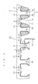
- the insulating layers 12 are formed on the portions excluding the outer periphery of the back yokes 2 and the inner periphery of the tees 3, as shown in Fig. 3. In other words, they are formed on the long side portions 2a of the back yokes 2, both sides of the tee bodies 3a and the outer peripheral surfaces of the converging portions 3b.
- Upper coverings 14, four upper supports 15 and positioning projections 19 are formed at the top of the back yokes 2 integrally therewith at the same time with the insulating layers 12, as shown in Figs. 4 and 5.
- Lower coverings 20 are also formed at the bottom of the back yokes 2 integrally therewith at the same time with the insulating layers 12.
- the upper coverings 14 have securing holes formed for securing binding pins 17 and 18 as will be described below.
- the four upper supports 15 protrude from the upper coverings 14 and define a table for mounting the wiring circuit board 51 and the positioning projections 19 protrude integrally from the upper supports 15.
- the upper supports 15 are formed on the fourth, sixth, tenth and twelfth tees 3 from the left end of the straight core 16, as shown in Fig. 4.
- a stack of laminas 1 having the insulating layers 12 formed thereon is called straight core 16.
- Three phase binding pins 17 each for one phase are first inserted in the securing hole of an upper covering 14 on or near the outer periphery of the back yokes 2 in the straight core 16 and caused to protrude from the straight core 16, as shown in Fig. 4. More specifically, the three phase binding pins 17 are caused to protrude from the outer periphery of one of the first, second and third tees 3 from the right end of the straight core 16. It is alternatively possible to cause the U-phase, V-phase and W-phase binding pins 17 to protrude from the first, second and third tees, respectively, from the right end of the straight core 16.
- a neutral point binding pin 18 is inserted in the securing hole of another upper covering 14 on or near the outer periphery of the back yokes 2 in the straight core 16 and caused to protrude from the straight core 16, as shown in Figs. 4 and 5. More specifically, the neutral point binding pin 18 is caused to protrude from the outer periphery of one of the first, second and third tees 3 from the left end of the straight core 16. (2-4) Winding Steps
- a nozzle 9 having a winding 8 passed therethrough is moved around each tee body 3a of the stator core 7 to have the winding 8 wound about the tee body 3a, as shown in Fig. 3.
- the winding is carried out on the tees 3 juxtaposed in parallel to one another.
- stator 10 has 12 tees 3
- three nozzles 9 are juxtaposed so as to correspond to three tees 3, respectively, and carry out winding about them simultaneously. After their winding, the nozzles are moved to other slots and such winding is repeated four times, whereby winding is carried out in all of the 12 slots.
- the winding for the U phase is carried out in the first, fourth, seventh and tenth slots from the left end of the straight core 16, the winding for the V phase in the second, fifth, eighth and eleventh slots, and the winding for the W phase in the third, sixth, ninth and twelfth slots.
- the windings 8 put about the tees 3 juxtaposed in parallel to one another achieve an improved ratio of occupation in each slot 6.
- the distance between either end of the converging portion 3b of one tee 3 and the adjacent end of the converging portion 3b of each adjoining tee 3 or the width of each opening 11 and the area of each slot 6 are greater than the width of each opening 11 and the area of each slot 6 which occur after the back yokes 2 are bent as will hereinafter be described.
- stator core 7 having 12 tees 3 does not have a large number of slots, it allows an efficient winding job and makes a motor having a good balance between its fabrication efficiency and characteristics.
- the U-phase winding 8 is bound with the U-phase binding pin 17 at one end and with the neutral point binding pin 18 at the other end.
- the V-phase winding 8 is bound with the V-phase binding pin 17 at one end and with the neutral point binding pin 18 at the other end.
- the W-phase winding 8 is bound with the W-phase binding pin 17 at one end and with the neutral point binding pin 18 at the other end.
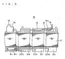
- the wiring for connecting the winding 8 for each phase to the neutral point binding pin 18 is made as shown in Fig. 5. More specifically, the other end of the U-phase winding 8 put around the tee 3 for the U phase is drawn to the top of the tee 3, then to the outer periphery of the upper covering 14 through its upper slot 14a and then to the neutral point binding pin 18 along the outer periphery of the upper covering 14 and is fastened to the neutral point binding pin 18. The same is repeated for the windings 8 for the other two phases.
- the wiring for connecting the winding 8 for each phase to the binding pin 17 for each phase is made as shown in Fig. 5. More specifically, one end of the U-phase winding 8 put around the tee 3 for the U phase is drawn to the bottom of the tee 3, then to the outer periphery of the lower covering 20 through its lower slot 20u and then to the U-phase binding pin 17 along the outer periphery of the lower covering 20 and is fastened to the U-phase binding pin 17. The same is repeated for the windings 8 for the other two phases.
- the lower slot 20u for the U phase, the lower slot 20v for the V phase and the lower slot 20w for the W phase have a greater depth in their order, so that the windings 8 for the three phases may lie in parallel to one another along the outer periphery of the lower covering 20 and not contact one another.
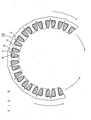
- the straight core 16 having the windings put thereon is bent at each cut 4 so that the tees 3 may be radially directed, as shown in Figs. 6 and 7.
- the back yokes 2 are bent into an annular shape.
- the opposite ends of the back yokes 2 are joined to each other by welding or with an adhesive.
- the inner rotor type stator 10 is formed.
- the cuts 4 have a cut angle which allows the opposite slanting surfaces of each cut 4 to contact each other when the back yokes 2 are formed into an annular shape.
- An insulator 13 is inserted between the winding 8 put around one tee 3 and the winding 8 put around any adjoining tee 3 in the event that they are likely to contact each other.
- the wiring circuit board 51 is disk-shaped and has a bushing 25 attached to its outer periphery.
- the bushing is made from a synthetic resin and is used for guiding a plurality of cords 26 from the wiring circuit board 51 to outside the motor 50.
- the disk-shaped wiring circuit board 51 is placed on the upper supports 15 of the stator 10 as shown in Fig. 8.
- the wiring circuit board 51 has four cut-off portions 23 made on its outer periphery and the four positioning projections 19 are fitted on the four cut-off portions 23, respectively, to position the wiring circuit board 51 relative to the stator 10.
- the four upper supports 15 formed on the fourth, sixth, tenth and twelfth tees 3 from the left end of the straight core 16 are arranged in a diametrically opposite relation, as shown in Fig. 8, to provide a stable mount for the wiring circuit board 51, while the positioning proj ections 19 ensure the coaxial positioning of the wiring circuit board 51 with the stator 10.
- the four positioning projections 19 situated in a diametrically opposite relation hold the wiring circuit board 51 against being pushed out by a molding resin during molding as will be described below.
- the wiring circuit board 51 has wiring patterns 24 and four connecting holes made for receiving the binding pins 17 for the three phases and the binding pin 18 for the neutral point, respectively.
- the binding pins 17 for the three phases and the binding pin 18 for the neutral point are inserted through the four connecting holes, respectively, and are soldered to the wiring patterns.
- the windings 8 for the three phases and the winding 8 for the neutral point can be connected to the wiring circuit board 51 easily.
- the motor frame 53 will now be described.
- the axis of the stator core 7 based on its inside diameter does not coincide with its axis based on its outside diameter, since the outside diameter of the stator 10 is not of a true circle. It is, therefore, difficult to assemble a motor by relying upon the outer periphery of the stator 10.
- a reduction in the mounting accuracy of rotary bearings, etc. on a motor frame made of a steel plate gives a product of low performance.
- the motor frame 53 is formed by molding from an insulating resin, or premix (hereinafter called the molding resin) by employing the inside diameter of the stator 10 as a standard for molding. More specifically, the inside diametrical portion of the stator 10 holding the wiring circuit board 51 as described above is fitted about a core in a resin mold not shown, and after the mold is closed, the molding resin is supplied at a high pressure into the mold. As a result, the stator core 7, wiring circuit board 51, etc. are integrally covered with the molding resin 52 to give a molded motor frame 53.
- the molding resin insulating resin
- the housing for holding the bearing 55 for supporting the rotor 56 and the socket portion 59 for holding the bracket 54 are formed at the same time by employing the inside diameter of the stator core 7 as a standard for molding, the axis of the stator core 7 based on its inside diameter, the axis of the housing and the axis of the socket portion 59 coincide with one another to give a motor of high accuracy having a uniform air gap.
- the bearing housing is coaxial with the stator 10, as it can be formed integrally with the motor frame 53 by employing the inside diameter of the stator 10 as a standard.
- the socket portion 59 with which the bracket 54 engages is also coaxial with the stator 10, as it is also formed with the motor frame 53.
- themotor frame 53 ensures a high accuracy of assembly.
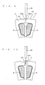
- Fig. 9 is an enlarged front elevational view of the joined ends 44 of a back yoke 2 according to the embodiment under description and their vicinity
- Fig. 10 is an enlarged front elevational view of the joined ends 44 of the back yoke 2 having a gap formed therebetween and their vicinity.
- a stator 10 is made by bending a straight core 16 into an annular shape, as stated with reference to the first embodiment.
- the opposite ends 44 of the back yokes 2 in the straight core 16 are crank-shaped as viewed from the axis of rotation.
- the back yokes 2 have projections 45a and 45b on their outer periphery at their opposite ends, respectively.
- the back yokes 2 are bent to have their projections 45a and 45b engage each other and a laser 46 is brought close to the projections 45a and 45b for welding them together.
- the structure as described ensures that even if any gap may be formed between the joined ends 44 of the back yokes 2 as shown in Fig. 10, bent surfaces 44a formed midway between the joined ends 44 form a wall preventing a laser beam from reaching the inside of the back yokes 2 and damaging the windings 8. Even if some gap or other may be formed between the joined ends 44 of the back yokes 2, the bent surfaces 44a of the joined ends 44 remain joined to each other, so that a magnetic path may be maintained as shown by an arrow in Fig. 10 to ensure a good flow of a magnetic flux.
- crank-shaped joined ends 44 mean that the back yokes 2 are joined at two points, i.e. the welded joint (projections 45a and 45b) and the bent surfaces 44a of the joined ends 44.
- the joined ends 44 are so high in rigidity as not to undergo resonance easily.
- the stator 10 is improved in its strength against a molding pressure prevailing in the event of the molding of the motor frame from a molding resin, and does not easily get separated at the joined ends 44.
- the joined ends 44 of the stator 10 may alternatively be formed by adhesion.
Landscapes
- Engineering & Computer Science (AREA)
- Power Engineering (AREA)
- Manufacture Of Motors, Generators (AREA)
- Insulation, Fastening Of Motor, Generator Windings (AREA)
- Iron Core Of Rotating Electric Machines (AREA)
Applications Claiming Priority (2)
| Application Number | Priority Date | Filing Date | Title |
|---|---|---|---|
| US10/699,093 US7015619B2 (en) | 2003-10-31 | 2003-10-31 | Molded motor |
| US699093 | 2003-10-31 |
Publications (2)
| Publication Number | Publication Date |
|---|---|
| EP1528655A2 true EP1528655A2 (de) | 2005-05-04 |
| EP1528655A3 EP1528655A3 (de) | 2005-10-12 |
Family
ID=34423434
Family Applications (1)
| Application Number | Title | Priority Date | Filing Date |
|---|---|---|---|
| EP04016138A Withdrawn EP1528655A3 (de) | 2003-10-31 | 2004-07-08 | Gegossener Motor |
Country Status (2)
| Country | Link |
|---|---|
| US (1) | US7015619B2 (de) |
| EP (1) | EP1528655A3 (de) |
Cited By (7)
| Publication number | Priority date | Publication date | Assignee | Title |
|---|---|---|---|---|
| EP1748531A1 (de) * | 2005-07-28 | 2007-01-31 | Siemens Aktiengesellschaft | Verfahren zur Herstellung eines Statorpaketes mit radial nach innen gerichteten Statorzähnen |
| WO2006113215A3 (en) * | 2005-04-15 | 2007-04-05 | Capital Formation Inc | Over molded stator |
| EP1783880A3 (de) * | 2005-11-04 | 2013-04-17 | Denso Corporation | Elektrischer Motor und Kraftstoffpumpe mit demselben |
| CN104081628A (zh) * | 2011-12-05 | 2014-10-01 | 菲舍尔和佩克尔应用有限公司 | 电机 |
| EP2356734B1 (de) * | 2008-11-14 | 2015-09-16 | Robert Bosch GmbH | Segmentierte stator-/rotorelemente von elektromotoren |
| CN104081628B (zh) * | 2011-12-05 | 2016-11-30 | 菲舍尔和佩克尔应用有限公司 | 电机 |
| US12374970B2 (en) | 2018-04-25 | 2025-07-29 | Borgwarner Sweden Ab | Stator |
Families Citing this family (24)
| Publication number | Priority date | Publication date | Assignee | Title |
|---|---|---|---|---|
| JP4631382B2 (ja) * | 2004-10-04 | 2011-02-16 | 日本電産株式会社 | ブラシレスモータ |
| JP4281733B2 (ja) * | 2005-11-21 | 2009-06-17 | トヨタ自動車株式会社 | 電気モータの分割ステータ |
| CN101461126B (zh) * | 2006-04-13 | 2016-01-27 | 雷勃电气美国公司 | 电机、用于电机的定子组件及其制造方法 |
| JP4316626B2 (ja) * | 2007-01-30 | 2009-08-19 | 三菱電機株式会社 | 回転電機 |
| WO2008123370A1 (ja) * | 2007-04-04 | 2008-10-16 | Kabushiki Kaisha Yaskawa Denki | 環状ステータコアとその製造方法、およびモールドモータ |
| TWI396362B (zh) * | 2009-06-09 | 2013-05-11 | Sunonwealth Electr Mach Ind Co | 馬達定子及其製造方法 |
| CN101931289B (zh) * | 2009-06-19 | 2014-03-26 | 建准电机工业股份有限公司 | 马达定子及其制造方法 |
| EP2580850B1 (de) | 2010-06-14 | 2021-11-10 | Black & Decker, Inc. | Steuereinheit für einen bürstenlosen motor in einem stromwerkzeug |
| US8410643B2 (en) * | 2010-07-22 | 2013-04-02 | Globe Motors, Inc. | Frameless electric motor assembly |
| JP5289521B2 (ja) * | 2010-12-29 | 2013-09-11 | 日本電産テクノモータ株式会社 | モールドモータ |
| CN103314506B (zh) * | 2011-01-18 | 2015-11-25 | 三菱电机株式会社 | 模制电动机和空调机 |
| TWI437799B (zh) * | 2011-07-21 | 2014-05-11 | Sunonwealth Electr Mach Ind Co | 封膠定子 |
| KR20150049036A (ko) * | 2013-10-29 | 2015-05-08 | 삼성전자주식회사 | 모터 및 스테이터 코일의 권선방법 |
| JP6578180B2 (ja) * | 2015-09-30 | 2019-09-18 | 日本電産サンキョー株式会社 | ステータ、モータおよびポンプ装置 |
| CN105553156B (zh) * | 2016-01-22 | 2018-11-13 | 珠海格力电器股份有限公司 | 一种用于电机定子的绝缘骨架及电机定子 |
| JP6844168B2 (ja) * | 2016-09-20 | 2021-03-17 | アイシン精機株式会社 | ステータおよびステータ製造方法 |
| CN110268604B (zh) * | 2017-02-14 | 2021-05-28 | 日本电产三协株式会社 | 电动机及泵装置 |
| JP6783198B2 (ja) * | 2017-07-18 | 2020-11-11 | 愛三工業株式会社 | ブラシレスモータ |
| JP2019068570A (ja) * | 2017-09-29 | 2019-04-25 | 日本電産株式会社 | モータ、及び、ステータ |
| JP6622774B2 (ja) * | 2017-10-10 | 2019-12-18 | ファナック株式会社 | ステータ及び電動機 |
| JP6967985B2 (ja) * | 2018-01-29 | 2021-11-17 | 三菱電機株式会社 | 回転電機のステータ、回転電機、回転電機のステータの製造方法、および、回転電機の製造方法 |
| JP7063092B2 (ja) * | 2018-04-27 | 2022-05-09 | 日本電産株式会社 | ステータユニット、モータ、及び送風装置 |
| JP6827098B1 (ja) * | 2019-12-26 | 2021-02-10 | 山洋電気株式会社 | 回転電動機及び一般電気機器 |
| US20260001262A1 (en) * | 2022-03-24 | 2026-01-01 | Nhk Spring Co., Ltd. | Stator manufacturing method |
Family Cites Families (18)
| Publication number | Priority date | Publication date | Assignee | Title |
|---|---|---|---|---|
| US4365180A (en) * | 1981-06-25 | 1982-12-21 | General Motors Corporation | Strip wound dynamoelectric machine core |
| US4651039A (en) * | 1985-02-08 | 1987-03-17 | Mitsubishi Denki Kabushiki Kaisha | Molded-type underwater motor |
| US4752707A (en) * | 1986-02-06 | 1988-06-21 | Morrill Wayne J | Three-phase, one-third pitch motor |
| JP2888142B2 (ja) * | 1993-11-08 | 1999-05-10 | 三菱電機株式会社 | 回転電動機並びにその製造方法 |
| US5489811A (en) * | 1992-06-11 | 1996-02-06 | Generac Corporation | Permanent magnet alternator |
| JP3541470B2 (ja) * | 1994-12-28 | 2004-07-14 | 株式会社安川電機 | モールドモータのコイル端末固定方法 |
| US6673463B1 (en) * | 1995-08-02 | 2004-01-06 | Matsushita Electric Industrial Co., Ltd. | Structure material and molded product using the same and decomposing method thereof |
| JPH09308143A (ja) | 1996-05-08 | 1997-11-28 | Matsushita Electric Ind Co Ltd | 回転電機のコア素材およびコアの製造方法 |
| JP3681487B2 (ja) | 1996-10-29 | 2005-08-10 | 日本電産シバウラ株式会社 | モールドモータ |
| JPH10271715A (ja) | 1997-03-25 | 1998-10-09 | Shibaura Eng Works Co Ltd | 固定子コア |
| TW411653B (en) * | 1997-04-11 | 2000-11-11 | Toshiba Corp | Stator for dynamoelectric machine and method of making the same |
| JP3359863B2 (ja) * | 1998-04-08 | 2002-12-24 | 三菱電機株式会社 | 固定子鉄芯の製造方法 |
| JPH11356022A (ja) * | 1998-06-03 | 1999-12-24 | Mitsubishi Electric Corp | モールドモータ |
| JP3318531B2 (ja) * | 1998-08-04 | 2002-08-26 | ミネベア株式会社 | 回転電機及びその軸受構造 |
| FR2804552B1 (fr) * | 2000-01-28 | 2003-01-03 | Leroy Somer | Procede de fabrication d'un circuit de machine electrique |
| JP2002176753A (ja) * | 2000-12-07 | 2002-06-21 | Matsushita Electric Ind Co Ltd | 電動機固定子の製造方法及びその固定子 |
| US6590310B2 (en) * | 2001-02-21 | 2003-07-08 | Kabushiki Kaisha Moric | Stator coil structure for revolving-field electrical machine and method of manufacturing same |
| JP2003244908A (ja) * | 2002-02-20 | 2003-08-29 | Mitsubishi Electric Corp | モールド電動機及び基板固定部品及び送風機及び空気調和機及びモールド電動機の製造方法及びモールド金型 |
-
2003
- 2003-10-31 US US10/699,093 patent/US7015619B2/en not_active Expired - Lifetime
-
2004
- 2004-07-08 EP EP04016138A patent/EP1528655A3/de not_active Withdrawn
Cited By (7)
| Publication number | Priority date | Publication date | Assignee | Title |
|---|---|---|---|---|
| WO2006113215A3 (en) * | 2005-04-15 | 2007-04-05 | Capital Formation Inc | Over molded stator |
| EP1748531A1 (de) * | 2005-07-28 | 2007-01-31 | Siemens Aktiengesellschaft | Verfahren zur Herstellung eines Statorpaketes mit radial nach innen gerichteten Statorzähnen |
| EP1783880A3 (de) * | 2005-11-04 | 2013-04-17 | Denso Corporation | Elektrischer Motor und Kraftstoffpumpe mit demselben |
| EP2356734B1 (de) * | 2008-11-14 | 2015-09-16 | Robert Bosch GmbH | Segmentierte stator-/rotorelemente von elektromotoren |
| CN104081628A (zh) * | 2011-12-05 | 2014-10-01 | 菲舍尔和佩克尔应用有限公司 | 电机 |
| CN104081628B (zh) * | 2011-12-05 | 2016-11-30 | 菲舍尔和佩克尔应用有限公司 | 电机 |
| US12374970B2 (en) | 2018-04-25 | 2025-07-29 | Borgwarner Sweden Ab | Stator |
Also Published As
| Publication number | Publication date |
|---|---|
| US7015619B2 (en) | 2006-03-21 |
| EP1528655A3 (de) | 2005-10-12 |
| US20050093379A1 (en) | 2005-05-05 |
Similar Documents
| Publication | Publication Date | Title |
|---|---|---|
| US7015619B2 (en) | Molded motor | |
| US6992419B2 (en) | Brushless direct-current motor of radial core type having a structure of double rotors and method for making the same | |
| US7348706B2 (en) | Stator assembly for an electric machine and method of manufacturing the same | |
| KR100545848B1 (ko) | 레이디얼 코어타입 더블 로터 방식의 비엘디씨 모터 및그의 제조방법 | |
| US9130426B2 (en) | Permanent magnet rotors and methods of assembling the same | |
| US20100141059A1 (en) | Capacitor motor and process for producing the same | |
| JP6843271B2 (ja) | 電動機及び空気調和機 | |
| US10923971B2 (en) | Stator, method of manufacturing stator, motor, and air conditioning apparatus | |
| US20080048529A1 (en) | Manufacturing method for stator core and for stepping motor, and stepping motor | |
| JP4942806B2 (ja) | 電動機の回転子及び電動機及び空気調和機及び電動機の製造方法 | |
| EP3306784B1 (de) | Bürstenloser motor und wickelverfahren für stator | |
| CN108475947B (zh) | 定子、马达以及定子的制造方法 | |
| US7084544B2 (en) | Brushless DC motor | |
| EP3324518B1 (de) | Anker, dynamoelektrische maschine, querstromlüfter | |
| CN108292872B (zh) | 转子、马达、空调装置及转子的制造方法 | |
| KR200338385Y1 (ko) | 몰드 모터 | |
| KR100724537B1 (ko) | 몰드 모터 | |
| JP4885616B2 (ja) | 3相回転電機 | |
| JPH10210688A (ja) | 電動機の固定子鉄心 | |
| WO2018074088A1 (ja) | 回転電機のステータとその製造方法 | |
| JPH10164788A (ja) | 永久磁石形同期電動機 | |
| JP2001112196A (ja) | 電動送風機 | |
| JP2015006069A (ja) | 回転電機及び回転電機の製造方法 | |
| JP2007116867A (ja) | ブラシレスモータ |
Legal Events
| Date | Code | Title | Description |
|---|---|---|---|
| PUAI | Public reference made under article 153(3) epc to a published international application that has entered the european phase |
Free format text: ORIGINAL CODE: 0009012 |
|
| AK | Designated contracting states |
Kind code of ref document: A2 Designated state(s): AT BE BG CH CY CZ DE DK EE ES FI FR GB GR HU IE IT LI LU MC NL PL PT RO SE SI SK TR |
|
| AX | Request for extension of the european patent |
Extension state: AL HR LT LV MK |
|
| PUAL | Search report despatched |
Free format text: ORIGINAL CODE: 0009013 |
|
| AK | Designated contracting states |
Kind code of ref document: A3 Designated state(s): AT BE BG CH CY CZ DE DK EE ES FI FR GB GR HU IE IT LI LU MC NL PL PT RO SE SI SK TR |
|
| AX | Request for extension of the european patent |
Extension state: AL HR LT LV MK |
|
| 17P | Request for examination filed |
Effective date: 20060320 |
|
| AKX | Designation fees paid |
Designated state(s): DE ES FR GB IT |
|
| 17Q | First examination report despatched |
Effective date: 20070522 |
|
| STAA | Information on the status of an ep patent application or granted ep patent |
Free format text: STATUS: THE APPLICATION IS DEEMED TO BE WITHDRAWN |
|
| 18D | Application deemed to be withdrawn |
Effective date: 20071002 |