EP1528625A2 - Antennenanordnung - Google Patents
Antennenanordnung Download PDFInfo
- Publication number
- EP1528625A2 EP1528625A2 EP04025557A EP04025557A EP1528625A2 EP 1528625 A2 EP1528625 A2 EP 1528625A2 EP 04025557 A EP04025557 A EP 04025557A EP 04025557 A EP04025557 A EP 04025557A EP 1528625 A2 EP1528625 A2 EP 1528625A2
- Authority
- EP
- European Patent Office
- Prior art keywords
- earphone
- line
- branch
- antenna device
- antenna
- Prior art date
- Legal status (The legal status is an assumption and is not a legal conclusion. Google has not performed a legal analysis and makes no representation as to the accuracy of the status listed.)
- Granted
Links
Images


Classifications
-
- H—ELECTRICITY
- H01—ELECTRIC ELEMENTS
- H01Q—ANTENNAS, i.e. RADIO AERIALS
- H01Q1/00—Details of, or arrangements associated with, antennas
- H01Q1/27—Adaptation for use in or on movable bodies
- H01Q1/273—Adaptation for carrying or wearing by persons or animals
-
- H—ELECTRICITY
- H01—ELECTRIC ELEMENTS
- H01Q—ANTENNAS, i.e. RADIO AERIALS
- H01Q1/00—Details of, or arrangements associated with, antennas
- H01Q1/44—Details of, or arrangements associated with, antennas using equipment having another main function to serve additionally as an antenna, e.g. means for giving an antenna an aesthetic aspect
Definitions
- the present invention relates to an antenna device for a compact wireless equipment, and more particularly, to an antenna device which is incorporated in an earphone connected to a compact wireless equipment.
- a portable FM radio may be used with an earphone which incorporates an antenna.
- the use of an earphone with a built-in antenna contributes to improved portability of FM radio because an antenna need not be additionally provided.
- an antenna built-in earphone for use with a portable FM radio a cable of the entire earphone from an earphone jack is utilized as an antenna.
- the earphone for use with a compact wireless equipment such as a portable FM radio typically has a cable of one to two meters long. Therefore, the antenna incorporated in the earphone can readily achieve a desired impedance and gain in a frequency band with long wavelengths such as the VHF band (the wavelength of which is on the order of ten to one meter).
- An earphone may be used with a mobile telephone in some cases, as disclosed in JP-04-200047-A where such an earphone incorporates an antenna.
- a mobile telephone described in JP-04-200047-A has an antenna disposed in a head unit, thereby enabling the user to set the mobile telephone at an arbitrary place when the earphone is used.
- the mobile telephone described in JP-04-200047-A has two antennas in the head unit such that one of the antennas can be selected by a switch for connection to the mobile telephone through a connection cord. This switching is intended to acquire a sufficient field strength by selecting an antenna which presents a higher field strength.
- the portable FM radio may be used with the earphone, the cable of which may be partially wound up, or partially placed in a pocket. Such a use would result in variations in impedance and gain of the antenna incorporated in the earphone, possibly failing to sufficiently manifest the effect of the antenna.
- one of the antennas disposed in the head unit is connected to the mobile telephone through the switch and connection cord.
- the entirety from the antenna in the head unit to the connection cord appears to be continuous, and functions as an antenna. Therefore, the antenna would experience variations in impedance and degraded characteristics if it is used with the wound-up connection cord or if it is placed in a pocket or a bag in its use.
- the antenna device of the present invention is integrated with an earphone for generating sound from an ear receiver, and connected to a radio through a connector to transmit an audio signal applied from the radio to the connector through a plurality of earphone signal lines.
- the antenna device includes an antenna element, a branch, and a coaxial line.
- the antenna element lies between the ear receiver and an intermediate position of an earphone signal line for transmitting the audio signal from the connector to the ear receiver.
- the branch is disposed at the intermediate position for preventing a high frequency signal on each of the plurality of earphone signal lines from passing therethrough, and for passing the audio signal therethrough to extract a signal received by the antenna element.
- a coaxial line transmits the signal received by the antenna element and extracted by the branch to the connector through the core line possessed thereby.
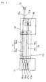
- Fig. 1 is a diagram illustrating an antenna device according to the first embodiment.
- the antenna device of this embodiment is integrated with an earphone which is connected to a compact wireless equipment.
- the antenna device comprises earphone cable 10, connector 11, branch 12, earphone signal line pair 15, and ear receiver 13.
- Connector 11 is connected to branch 12 through earphone cable 10.
- Branch 12 is connected to ear receiver 13 through earphone signal line pair 15.
- Earphone cable 10 comprises coaxial line 14 composed of shield line 14a and core line 14b; earphone signal line pair 19 composed of earphone audio line 19b and earphone GND line 19a; and a single sheath which covers both coaxial line 14 and earphone signal line pair 19.
- Connector 11 comprises antenna terminal 16a, antenna GND terminal 16b, earphone terminal 17a, and earphone GND terminal 17b.
- Earphone signal line pair 15 comprises earphone audio line 15b, and earphone GND line 15a.
- Branch 12 has high frequency separator 18.
- antenna terminal 16a is connected to core line 14b; antenna GND terminal 16b is connected to shield line 14a; earphone terminal 17b is connected to earphone audio line 19b; and earphone GND terminal 17a is connected to earphone GND line 19a.
- core line 14b is connected to earphone audio line 15b.
- Shield line 14a is open toward branch 12.
- earphone audio line 15b is connected to earphone audio line 19b through high frequency separator 18.
- Earphone GND line 15a is also connected to earphone GND line 19a through high frequency separator 18.
- High frequency separator 18 has inductor 18b connected in series between earphone audio line 15b and earphone audio line 19b; and inductor 18a connected in series between earphone GND line 15a and earphone GND line 19a. Inductance values of inductors 18a, 18b are determined to be sufficiently low over a frequency range of audio signals, and to be sufficiently high over a frequency range of high frequency signals received by the antenna device.
- Connector 11 which is inserted into a receptacle of a compact wireless equipment (not shown) for an earphone which also functions as an antenna, transmits an audio signal from the compact wireless equipment to earphone signal line pair 19, and transmit high frequency signals received by the antenna device to the compact wireless equipment.
- Ear receiver 13 which has a speaker, is mounted on an ear of the user of the compact radio, and generates sound in accordance with an audio signal applied thereto.
- An audio signal applied between earphone terminal 17b and earphone GND terminal 17a from the compact wireless equipment reaches ear receiver 13 through earphone signal line pair 19, high frequency separator 18, and earphone signal line pair 15. Since the audio signal has low frequencies, it passes through high frequency separator 18. With the audio signal reaching ear receiver 13, sound is generated from ear receiver 13.
- earphone audio line 15b between branch 12 and ear receiver 13 functions as an antenna element.
- a signal received by this antenna element is transmitted over coaxial line 14, and applied to the compact wireless equipment from antenna terminal 16a.
- coaxial line 14 is in close proximity to earphone signal line pair 19, capacitive coupling occurs therebetween.
- inductors 18a, 18b are inserted both in the earphone audio line 19b and earphone GND line 19a, a high frequency signal generated on earphone signal line pair 19 due to capacitive coupling in earphone cable 10 is blocked by high frequency separator 18, and is prevented from flowing to ear receiver 13.
- the antenna device of this embodiment uses earphone audio line 15b as an antenna element, transmits a signal received by this antenna element from branch 12 to connector 11 through coaxial line 14, and removes high frequency noise due to capacitive coupling between coaxial line 14 and earphone audio line 19b and earphone GND line 19a by high frequency separator 18 of branch 12. Consequently, during a communication using the earphone, radio waves can be received only by earphone audio line 15b near ear receiver 13 which would never be wound up or placed in a pocket, with few fluctuations in impedance and reduction in gain. Also, since high frequency separator 18 removes the influence of the capacitive coupling between coaxial line 14 and earphone audio line 19b and earphone GND line 19a on an audio signal, high quality sound can be generated from ear receiver 13.
- earphone audio line 19b and earphone GND line 19a could be passed through shield line 14a together with core line 14b.
- earphone audio line 19b and earphone GND line 19a are preferably passed outside of shield line 14a in consideration of impedance matching and reduced gain.
- earphone cable 10 which has coaxial line 14 and earphone signal line pair 19 covered with a single sheath
- a cable in another structure may be used instead of the illustrated one.
- Fig. 2 is a diagram illustrating an example which employs a twin cable as earphone cable 10 between connector 11 and branch 12. Referring to Fig. 2, earphone cable 10 implemented by the twin cable has coaxial line 14 and earphone signal line pair 19 which are each covered with an individual sheath, and are joined together.
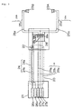
- Fig. 3 is a diagram illustrating an antenna device according to the second embodiment.
- the antenna device of this embodiment differs from the first embodiment in that the antenna device is integrated with a stereo-type earphone.
- the antenna device comprises earphone cable 20, connector 21, branch 22, earphone signal line pairs 25A, 25B, and ear receivers 23A, 23B.
- Connector 21 is connected to branch 22 through earphone cable 20.
- Branch 22 is connected to ear receiver 23A through earphone signal line pair 25A, while branch 22 is connected to ear receiver 23B through earphone signal line pair 25B.
- Earphone cable 20 comprises coaxial line 24 composed of shield line 24a and core line 24b; earphone signal lines 29 composed of earphone L-ch audio line 29a, earphone R-ch audio line 29b, and earphone GND line 29c; and a single sheath which covers both coaxial line 24 and earphone signal lines 29.
- L-ch indicates the left channel of the stereo, while R-ch indicates the right channel of the same.
- Earphone GND line 29c is shared by L-ch and R-ch.
- Connector 21 comprises antenna terminal 26a, antenna GND terminal 26b, earphone L-ch terminal 27a, earphone R-ch terminal 27b, and earphone GND terminal 27c.
- Earphone signal line pair 25A comprises earphone L-ch audio line 25a and earphone L-ch GND line 25b.
- Earphone signal line pair 25B comprises earphone R-ch audio line 25c and earphone R-ch GND line 25d.
- Branch 22 has high frequency separator 28.
- antenna terminal 26a is connected to core line 24b; antenna GND terminal 26b is connected to shield line 24a; earphone L-ch terminal 27a is connected to earphone L-ch audio line 29a; earphone R-ch terminal 27b is connected to earphone R-ch audio line 29b; and earphone GND terminal 27c is connected to earphone GND line 29c.
- core line 24b is connected to earphone L-ch audio line 25a and to earphone R-ch audio line 25c.
- Shield line 24a is open toward branch line 22.
- earphone L-ch audio line 25a is connected to earphone L-ch audio line 29a through high-frequency separator 28.
- Earphone R-ch audio line 25c is connected to earphone R-ch audio line 29b through high frequency separator 28.
- Earphone L-ch GND line 25b and earphone R-ch GND line 25d which are connected in common, is connected to earphone GND line 29c through high frequency separator 28.
- High frequency separator 28 has inductor 28a connected in series between earphone L-ch audio line 25a and earphone L-ch audio line 29a; inductor 28b connected in series between earphone R-ch audio line 25c and earphone R-ch audio line 29b; and inductor 28c connected in series between a juncture of earphone L-ch GND line 25b and earphone R-ch GND line 25d and earphone GND line 29c.
- the inductance values of inductors 28a, 28b, 28c are determined such that the impedance values are sufficiently low over a frequency range of audio signals and sufficiently high over a frequency range of high frequency signal received by the antenna device.
- Connector 21 which is inserted into a receptacle of a compact wireless equipment (not shown) for an earphone which also functions as an antenna, transmits an L-ch audio signal from the compact wireless equipment to earphone L-ch audio line 29a; an R-ch audio signal to earphone R-ch audio line 29b; and a high-frequency signal received by the antenna from coaxial line 24 to the compact wireless equipment.
- Ear receivers 23A, 23B each of which has a speaker, are mounted on the respective ears of the user of the compact wireless equipment, and generate sound in accordance with each of L-ch and R-ch audio signals applied thereto.
- An L-ch audio signal applied between earphone L-ch terminal 27a and earphone GND terminal 27c from the compact wireless equipment reaches ear receiver 23A through earphone L-ch audio line 29a, high frequency separator 28, and earphone signal line pair 25A.
- an R-ch audio signal applied between earphone R-ch terminal 27b and earphone GND terminal 27c from the compact wireless equipment reaches ear receiver 23B through earphone R-ch audio line 29b, high frequency separator 28, and earphone signal line pair 25B. Since L-ch and R-ch audio signals have low frequencies, they pass through high frequency separator 28. With the audio signals reaching ear receivers 23A, 23B, sound is generated from ear receivers 23A, 23B.
- both earphone L-ch audio line 25a between branch 22 and ear receiver 23A, and earphone R-ch audio line 25c between branch line 22 and ear receiver 23B function as an antenna element.
- the antenna device of the second embodiment can take a longer antenna element than that of the first embodiment, thus providing more satisfactory antenna characteristics.
- a signal received by the antenna element is transmitted through coaxial line 24 and applied to the compact wireless equipment from antenna terminal 26a.
- coaxial line 24 is in close proximity to earphone signal lines 29, capacitive coupling occurs therebetween.
- inductors 28a - 28c are inserted in all of the earphone L-ch, R-ch audio lines and earphone GND line, a high frequency signal generated on earphone signal lines 29 due to capacitive coupling in earphone cable 20 is blocked by high frequency separator 28, and is prevented from flowing to ear receivers 23A, 23B.
- the antenna device of the second embodiment can take a longer antenna element, in addition to similar advantages offered by the first embodiment, thus providing further satisfactory antenna characteristics.
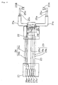
- An antenna device of the third embodiment is similar to the second embodiment in that the antenna device is integrated with a stereo-type earphone.
- the third embodiment differs from the second embodiment in that coaxial lines are used between branch 22 and ear receivers 23A, 23B, and shield lines of the coaxial lines function as antenna elements. In this way, L-ch and R-ch audio signals and signals received by the antenna elements can be separated between branch 22 and ear receivers 23A, 23B.
- Fig. 4 is a diagram illustrating the antenna device according to the third embodiment.
- Branch 22 is connected to ear receiver 23A through a coaxial line which has earphone L-ch audio line 25a and earphone L-ch GND line 25b passing through earphone L-ch shield line 31 a.
- branch 22 is connected to ear receiver 23B through a coaxial line which has earphone R-ch audio line 25c and earphone R-ch GND line 25d passing through earphone R-ch shield line 31 b.
- core line 24b is connected to earphone L-ch shield line 31 a and to earphone R-ch shield line 31 b.
- Earphone L-ch shield line 31 a is open toward ear receiver 23A, as is earphone R-ch shield line 31 b open toward ear receiver 23B.
- the rest of Fig. 4 is identical to Fig. 3.
- the antenna device of the third embodiment since audio signals are separated from signals received by the antenna elements between branch 22 and ear receivers 23A, 23B, the antenna device can further reduce noise possibly introduced into the audio signal, in addition to similar advantages offered by the second embodiment.
- An antenna device of the fourth embodiment is also similar to the second and third embodiments in that the antenna device is integrated with a stereo-type earphone.
- the fourth embodiment differs from the second embodiment in that GND lines between a branch and ear receivers function as an antenna element, and that a lumped-constant matching circuit is provided in the branch for achieving impedance matching between the antenna element and a core line between the connector and branch. With this configuration, it is possible to prevent a degraded gain due to impedance mismatch in the branch.
- Fig. 5 is a diagram illustrating an antenna device according to the fourth embodiment.
- Branch 41 has a predetermined lumped-constant matching circuit 42 other than high frequency separator 28.
- core line 24b of coaxial line 24 between connector 21 and branch 41 is connected to earphone both L-ch GND line 25b and earphone R-ch GND line 25d, which function as an antenna element, through matching circuit 42.
- the antenna device of the fourth embodiment since impedance matching can be achieved between core line 24b of coaxial line 24 and the antenna element by matching circuit 42, in addition to similar advantages offered by the second embodiment, the antenna device can prevent a reduced gain caused by impedance mismatch.
- the antenna device of the fifth embodiment is also similar to the second to fourth embodiments in that the antenna device is integrated with a stereo-type earphone, and is also similar to the fourth embodiment in that the GND lines between the branch and ear receivers function as an antenna element.
- the fifth embodiment differs from the fourth embodiment in that impedance matching between the antenna element and a core line between the connector and branch is achieved by a distributed-constant stub circuit.
- the fifth embodiment is identical to the fourth embodiment in that it is intended to prevent a reduced gain caused by impedance mismatch.
- Fig. 6 is a diagram illustrating the antenna device according to the fifth embodiment.
- Stub circuit 52 is covered with a sheath together with coaxial line 24 and earphone signal lines 29, and contained in earphone cable 50.
- Branch 51 has a wiring structure for connecting coaxial line 24 to stub circuit 52 instead of a matching circuit.
- the antenna device of the fifth embodiment can provide similar operational advantages to the fourth embodiment.
- An antenna device of the sixth embodiment is again similar to the second to fifth embodiments in that the antenna device is integrated with a stereo-type earphone, and is also similar to the fourth and fifth embodiments in that GND lines between a branch and ear receivers are used as an antenna element.
- Fig. 7 is a diagram illustrating the antenna device according to the sixth embodiment.
- relay 62 is provided between connector 21 and branch 61.
- Relay 62 simply passes L-ch and R-ch audio signals on earphone signal lines 29 therethrough.
- relay 62 has a matching adjuster 63 between coaxial line 24A, which is connected between connector 21 and relay 62, and coaxial line 24B,which is connected between relay 62 and branch 61.
- Matching adjuster 63 achieves impedance matching between connector 21 and branch 61 with a predetermined lumped constant.
- the lumped constant is determined to be a value which satisfactorily adjusts the impedance characteristics, when viewed from connector 21, in consideration of the impedance characteristics in branch 61.
Landscapes
- Input Circuits Of Receivers And Coupling Of Receivers And Audio Equipment (AREA)
- Headphones And Earphones (AREA)
- Details Of Aerials (AREA)
- Support Of Aerials (AREA)
Priority Applications (1)
| Application Number | Priority Date | Filing Date | Title |
|---|---|---|---|
| EP08000951A EP1947735A3 (de) | 2003-10-29 | 2004-10-27 | Antennenvorrichtung |
Applications Claiming Priority (2)
| Application Number | Priority Date | Filing Date | Title |
|---|---|---|---|
| JP2003368862A JP3880571B2 (ja) | 2003-10-29 | 2003-10-29 | アンテナ装置 |
| JP2003368862 | 2003-10-29 |
Related Child Applications (1)
| Application Number | Title | Priority Date | Filing Date |
|---|---|---|---|
| EP08000951A Division EP1947735A3 (de) | 2003-10-29 | 2004-10-27 | Antennenvorrichtung |
Publications (3)
| Publication Number | Publication Date |
|---|---|
| EP1528625A2 true EP1528625A2 (de) | 2005-05-04 |
| EP1528625A3 EP1528625A3 (de) | 2005-07-13 |
| EP1528625B1 EP1528625B1 (de) | 2008-08-27 |
Family
ID=34420162
Family Applications (2)
| Application Number | Title | Priority Date | Filing Date |
|---|---|---|---|
| EP04025557A Expired - Lifetime EP1528625B1 (de) | 2003-10-29 | 2004-10-27 | Antennenanordnung |
| EP08000951A Withdrawn EP1947735A3 (de) | 2003-10-29 | 2004-10-27 | Antennenvorrichtung |
Family Applications After (1)
| Application Number | Title | Priority Date | Filing Date |
|---|---|---|---|
| EP08000951A Withdrawn EP1947735A3 (de) | 2003-10-29 | 2004-10-27 | Antennenvorrichtung |
Country Status (5)
| Country | Link |
|---|---|
| US (1) | US7292705B2 (de) |
| EP (2) | EP1528625B1 (de) |
| JP (1) | JP3880571B2 (de) |
| CN (1) | CN1328822C (de) |
| DE (1) | DE602004016101D1 (de) |
Cited By (2)
| Publication number | Priority date | Publication date | Assignee | Title |
|---|---|---|---|---|
| EP2088804A1 (de) * | 2008-02-06 | 2009-08-12 | Starkey Laboratories, Inc. | Antenne, die in Verbindung mit den Leitern verwendet wird, für einen Audiowandler |
| EP1971179A4 (de) * | 2005-12-19 | 2010-05-19 | Ad Plan Co Ltd | Mit ohrhörer ausgestattete antenne und ohrhörer |
Families Citing this family (47)
| Publication number | Priority date | Publication date | Assignee | Title |
|---|---|---|---|---|
| JP4026648B2 (ja) | 2004-04-19 | 2007-12-26 | ソニー株式会社 | イヤホンアンテナ及びこのイヤホンアンテナを備えた携帯型無線機 |
| JP3933148B2 (ja) | 2004-06-04 | 2007-06-20 | ソニー株式会社 | イヤホンアンテナ及びこのイヤホンアンテナを備えた携帯型無線機 |
| WO2006046714A1 (ja) * | 2004-10-28 | 2006-05-04 | Matsushita Electric Industrial Co., Ltd. | 放送用受信機付き携帯電話 |
| WO2006081260A2 (en) * | 2005-01-25 | 2006-08-03 | Siport, Inc. | Mobile device multi-antenna system |
| JP4372154B2 (ja) * | 2005-02-02 | 2009-11-25 | パナソニック株式会社 | 接続ケーブル一体型アンテナ装置及び無線機器 |
| WO2006102631A2 (en) | 2005-03-24 | 2006-09-28 | Siport, Inc. | Low power digital media broadcast receiver with time division |
| US20070025579A1 (en) * | 2005-07-27 | 2007-02-01 | Kolton Timothy V | Interchangeable personal audio device cables and cable covers |
| US8335484B1 (en) | 2005-07-29 | 2012-12-18 | Siport, Inc. | Systems and methods for dynamically controlling an analog-to-digital converter |
| JP4123262B2 (ja) | 2005-10-07 | 2008-07-23 | ソニー株式会社 | イヤホンアンテナ |
| JP4569449B2 (ja) * | 2005-11-22 | 2010-10-27 | ソニー株式会社 | 受信機 |
| JP2007150386A (ja) * | 2005-11-24 | 2007-06-14 | Mitsumi Electric Co Ltd | イヤホンアンテナ |
| JP5180058B2 (ja) * | 2006-02-14 | 2013-04-10 | パナソニック株式会社 | イヤホン接続ケーブル及び該イヤホン接続ケーブルを備えた携帯機器 |
| JP2007221366A (ja) * | 2006-02-15 | 2007-08-30 | Matsushita Electric Ind Co Ltd | 接続ケーブルおよび携帯端末 |
| US7706849B2 (en) * | 2006-02-22 | 2010-04-27 | Mediatek Inc. | Mobile communication devices with internal antennas |
| JP4800817B2 (ja) * | 2006-03-31 | 2011-10-26 | 京セラ株式会社 | 携帯端末機 |
| US8094673B2 (en) * | 2006-04-10 | 2012-01-10 | Microsoft Corporation | Cable user interface |
| JP4715603B2 (ja) * | 2006-04-12 | 2011-07-06 | ソニー株式会社 | アンテナ装置 |
| JP4904895B2 (ja) * | 2006-04-12 | 2012-03-28 | ソニー株式会社 | アンテナ装置 |
| WO2007138669A1 (ja) * | 2006-05-29 | 2007-12-06 | Panasonic Corporation | Acアダプタ及び携帯端末装置 |
| JP4743148B2 (ja) * | 2007-04-10 | 2011-08-10 | ソニー株式会社 | 受信装置及びアンテナ |
| US8199769B2 (en) | 2007-05-25 | 2012-06-12 | Siport, Inc. | Timeslot scheduling in digital audio and hybrid audio radio systems |
| US8934984B2 (en) | 2007-05-31 | 2015-01-13 | Cochlear Limited | Behind-the-ear (BTE) prosthetic device with antenna |
| CN101359764B (zh) * | 2007-07-30 | 2013-08-28 | 宏达国际电子股份有限公司 | 耳机天线 |
| TWI366947B (en) * | 2007-07-30 | 2012-06-21 | Htc Corp | Headset antenna and connector thereof |
| WO2009083812A1 (en) | 2007-12-20 | 2009-07-09 | Nxp B.V. | Headset loop antenna for audio devices |
| DK2076065T4 (en) † | 2007-12-27 | 2017-02-20 | Oticon As | Hearing aid and method for wireless reception and / or transmission of data |
| US8606195B2 (en) * | 2008-06-27 | 2013-12-10 | Sharp Kabushiki Kaisha | Radio |
| JP2010057115A (ja) * | 2008-08-29 | 2010-03-11 | Japan Radio Co Ltd | 空中線整合装置 |
| US8320823B2 (en) | 2009-05-04 | 2012-11-27 | Siport, Inc. | Digital radio broadcast transmission using a table of contents |
| US8208884B2 (en) * | 2009-10-28 | 2012-06-26 | Silicon Laboratories Inc. | Method and system for FM tuner ground isolation when using ground signal line as FM antenna |
| EP2458674A3 (de) | 2010-10-12 | 2014-04-09 | GN ReSound A/S | Antennensystem für ein Hörgerät |
| EP2458675B1 (de) | 2010-10-12 | 2017-12-06 | GN Hearing A/S | Hörgerät mit Antenne |
| US8489053B2 (en) | 2011-01-16 | 2013-07-16 | Siport, Inc. | Compensation of local oscillator phase jitter |
| DK201270410A (en) | 2012-07-06 | 2014-01-07 | Gn Resound As | BTE hearing aid with an antenna partition plane |
| US9554219B2 (en) | 2012-07-06 | 2017-01-24 | Gn Resound A/S | BTE hearing aid having a balanced antenna |
| DK201270411A (en) | 2012-07-06 | 2014-01-07 | Gn Resound As | BTE hearing aid having two driven antennas |
| US9237404B2 (en) | 2012-12-28 | 2016-01-12 | Gn Resound A/S | Dipole antenna for a hearing aid |
| EP3657600A1 (de) | 2013-08-09 | 2020-05-27 | Oticon A/s | Hörgerät mit hf-antenne |
| KR102092857B1 (ko) * | 2013-10-25 | 2020-03-25 | 삼성전자주식회사 | 청각 기기용 누설파 안테나 |
| US9237405B2 (en) | 2013-11-11 | 2016-01-12 | Gn Resound A/S | Hearing aid with an antenna |
| US9883295B2 (en) | 2013-11-11 | 2018-01-30 | Gn Hearing A/S | Hearing aid with an antenna |
| US9408003B2 (en) | 2013-11-11 | 2016-08-02 | Gn Resound A/S | Hearing aid with an antenna |
| US9686621B2 (en) | 2013-11-11 | 2017-06-20 | Gn Hearing A/S | Hearing aid with an antenna |
| US10595138B2 (en) | 2014-08-15 | 2020-03-17 | Gn Hearing A/S | Hearing aid with an antenna |
| KR20170136293A (ko) * | 2016-06-01 | 2017-12-11 | 엘지전자 주식회사 | 휴대용 음향기기 |
| US11005164B2 (en) * | 2017-03-31 | 2021-05-11 | Amotech Co., Ltd. | Ring-shaped antenna and earphone module having same |
| CN112243066B (zh) * | 2020-10-20 | 2021-07-23 | Oppo广东移动通信有限公司 | 电子设备fm播放方式的选择方法及电子设备 |
Family Cites Families (22)
| Publication number | Priority date | Publication date | Assignee | Title |
|---|---|---|---|---|
| US2899549A (en) * | 1959-08-11 | Antenna and audio connector | ||
| GB962100A (en) * | 1963-06-14 | 1964-06-24 | County Council Of The Administ | Improvements in transportable radio apparatus |
| JPS5714505U (de) * | 1980-06-26 | 1982-01-25 | ||
| JPH01172731A (ja) | 1987-12-26 | 1989-07-07 | Hokuriku Nogyo Shikenjo | 真空吸引管を利用した土壌溶液の採取法 |
| JPH03109414A (ja) | 1989-09-21 | 1991-05-09 | Sanyo Chem Ind Ltd | 難燃性ポリウレタンフォームの製法 |
| JPH04200047A (ja) * | 1990-11-29 | 1992-07-21 | Matsushita Electric Ind Co Ltd | 携帯電話装置 |
| US5301361A (en) * | 1990-12-28 | 1994-04-05 | Samson Technologies | Low parts count transmitter unit |
| JPH07107148A (ja) | 1993-09-29 | 1995-04-21 | Sony Corp | 携帯電話 |
| JPH07298384A (ja) | 1994-04-26 | 1995-11-10 | Sony Corp | ヘッドホン |
| JP3635722B2 (ja) | 1995-07-12 | 2005-04-06 | ソニー株式会社 | ヘッドホン用受信装置 |
| JPH09331209A (ja) | 1996-04-09 | 1997-12-22 | Sony Corp | Fm受信回路を有するオーディオ機器およびヘッドホン |
| JPH09312894A (ja) | 1996-05-22 | 1997-12-02 | Sony Corp | Fm受信機 |
| US6377225B1 (en) * | 2000-07-07 | 2002-04-23 | Texas Instruments Incorporated | Antenna for portable wireless devices |
| JP3678179B2 (ja) * | 2001-07-25 | 2005-08-03 | 日立電線株式会社 | 2重横巻2心平行極細同軸ケーブル |
| GB0122261D0 (en) * | 2001-09-17 | 2001-11-07 | Roke Manor Research | Headphone antenna for vhf radio |
| EP1428410A2 (de) * | 2001-09-17 | 2004-06-16 | Roke Manor Research Limited | Kophörer |
| GB0127566D0 (en) * | 2001-11-19 | 2002-01-09 | Psion Digital Ltd | Antenna for a portable radio device |
| JP2003163529A (ja) * | 2001-11-28 | 2003-06-06 | Alps Electric Co Ltd | ダイバーシチアンテナ兼用ヘッドホン |
| US7558607B2 (en) * | 2002-06-12 | 2009-07-07 | Nokia Corporation | Mobile electronic device having audio connector providing an antenna function |
| JP4363865B2 (ja) * | 2003-02-28 | 2009-11-11 | ソニー株式会社 | イヤーホーンアンテナ及び無線機 |
| JP3938118B2 (ja) | 2003-08-08 | 2007-06-27 | ソニー株式会社 | イヤホンアンテナ及びこのイヤホンアンテナを備えた携帯型無線機 |
| US7411559B2 (en) * | 2004-06-29 | 2008-08-12 | Nokia Corporation | Headset loop antenna |
-
2003
- 2003-10-29 JP JP2003368862A patent/JP3880571B2/ja not_active Expired - Fee Related
-
2004
- 2004-10-27 EP EP04025557A patent/EP1528625B1/de not_active Expired - Lifetime
- 2004-10-27 US US10/973,913 patent/US7292705B2/en not_active Expired - Fee Related
- 2004-10-27 CN CNB2004100869884A patent/CN1328822C/zh not_active Expired - Fee Related
- 2004-10-27 EP EP08000951A patent/EP1947735A3/de not_active Withdrawn
- 2004-10-27 DE DE602004016101T patent/DE602004016101D1/de not_active Expired - Lifetime
Cited By (6)
| Publication number | Priority date | Publication date | Assignee | Title |
|---|---|---|---|---|
| EP1971179A4 (de) * | 2005-12-19 | 2010-05-19 | Ad Plan Co Ltd | Mit ohrhörer ausgestattete antenne und ohrhörer |
| EP2088804A1 (de) * | 2008-02-06 | 2009-08-12 | Starkey Laboratories, Inc. | Antenne, die in Verbindung mit den Leitern verwendet wird, für einen Audiowandler |
| US8867765B2 (en) | 2008-02-06 | 2014-10-21 | Starkey Laboratories, Inc. | Antenna used in conjunction with the conductors for an audio transducer |
| US9516432B2 (en) | 2008-02-06 | 2016-12-06 | Starkey Laboratories, Inc. | Antenna used in conjunction with the conductors for an audio transducer |
| US10798496B2 (en) | 2008-02-06 | 2020-10-06 | Starkey Laboratories, Inc. | Antenna used in conjunction with the conductors for an audio transducer |
| US11653157B2 (en) | 2008-02-06 | 2023-05-16 | Starkey Laboratories, Inc. | Antenna used in conjunction with the conductors for an audio transducer |
Also Published As
| Publication number | Publication date |
|---|---|
| US7292705B2 (en) | 2007-11-06 |
| JP2005136587A (ja) | 2005-05-26 |
| JP3880571B2 (ja) | 2007-02-14 |
| EP1947735A3 (de) | 2011-07-20 |
| CN1612411A (zh) | 2005-05-04 |
| EP1528625B1 (de) | 2008-08-27 |
| EP1528625A3 (de) | 2005-07-13 |
| CN1328822C (zh) | 2007-07-25 |
| US20050094840A1 (en) | 2005-05-05 |
| DE602004016101D1 (de) | 2008-10-09 |
| EP1947735A2 (de) | 2008-07-23 |
Similar Documents
| Publication | Publication Date | Title |
|---|---|---|
| US7292705B2 (en) | Antenna device | |
| US7840242B2 (en) | Earphone antenna | |
| CN101202372B (zh) | 耳机天线装置和连接该装置的无线通信终端 | |
| US7558607B2 (en) | Mobile electronic device having audio connector providing an antenna function | |
| US7559803B2 (en) | Connection structure and signal transmission cable | |
| JP3851339B1 (ja) | イヤホン付きアンテナ及びイヤホン | |
| CA2460658A1 (en) | A headphone | |
| EP2611211B1 (de) | Kopfhörerkabelanordnung, Filterbaugruppe, und Verfahren zur Filterung von Signalen in Kopferkabelanordnungen | |
| JP2006222892A (ja) | イヤホンアンテナ | |
| JP4743148B2 (ja) | 受信装置及びアンテナ | |
| JP2005354275A (ja) | イヤホンマイクロホン | |
| JP2006287720A (ja) | イヤホンアンテナ | |
| CN101621155A (zh) | 接收装置、天线以及中继电缆 | |
| US8140114B2 (en) | Receiving device and antenna | |
| JP4962106B2 (ja) | アンテナケーブル | |
| JP4973529B2 (ja) | 受信システム、受信装置及び中継ケーブル | |
| GB2380861A (en) | Headphone lead/antenna system | |
| KR101077365B1 (ko) | 휴대용 기기의 다기능 이어폰 | |
| JP2008035465A (ja) | ダイポールアンテナ装置、イアホンアンテナ装置および上記装置と接続する無線通信端末 | |
| JP2006287721A (ja) | イヤホンマイクロホン | |
| EP2280487A1 (de) | Tragbarer drahtloser Empfänger-Vorrechner mit mehreren Eingängen | |
| AU2002342732A1 (en) | A headphone |
Legal Events
| Date | Code | Title | Description |
|---|---|---|---|
| PUAI | Public reference made under article 153(3) epc to a published international application that has entered the european phase |
Free format text: ORIGINAL CODE: 0009012 |
|
| AK | Designated contracting states |
Kind code of ref document: A2 Designated state(s): AT BE BG CH CY CZ DE DK EE ES FI FR GB GR HU IE IT LI LU MC NL PL PT RO SE SI SK TR |
|
| AX | Request for extension of the european patent |
Extension state: AL HR LT LV MK |
|
| PUAL | Search report despatched |
Free format text: ORIGINAL CODE: 0009013 |
|
| RIC1 | Information provided on ipc code assigned before grant |
Ipc: 7H 04B 1/18 B Ipc: 7H 01Q 1/44 A Ipc: 7H 01Q 1/27 B |
|
| AK | Designated contracting states |
Kind code of ref document: A3 Designated state(s): AT BE BG CH CY CZ DE DK EE ES FI FR GB GR HU IE IT LI LU MC NL PL PT RO SE SI SK TR |
|
| AX | Request for extension of the european patent |
Extension state: AL HR LT LV MK |
|
| 17P | Request for examination filed |
Effective date: 20050603 |
|
| AKX | Designation fees paid |
Designated state(s): DE FR GB IT |
|
| GRAP | Despatch of communication of intention to grant a patent |
Free format text: ORIGINAL CODE: EPIDOSNIGR1 |
|
| GRAS | Grant fee paid |
Free format text: ORIGINAL CODE: EPIDOSNIGR3 |
|
| GRAA | (expected) grant |
Free format text: ORIGINAL CODE: 0009210 |
|
| AK | Designated contracting states |
Kind code of ref document: B1 Designated state(s): DE FR GB IT |
|
| REG | Reference to a national code |
Ref country code: GB Ref legal event code: FG4D |
|
| REF | Corresponds to: |
Ref document number: 602004016101 Country of ref document: DE Date of ref document: 20081009 Kind code of ref document: P |
|
| PLBE | No opposition filed within time limit |
Free format text: ORIGINAL CODE: 0009261 |
|
| STAA | Information on the status of an ep patent application or granted ep patent |
Free format text: STATUS: NO OPPOSITION FILED WITHIN TIME LIMIT |
|
| 26N | No opposition filed |
Effective date: 20090528 |
|
| PGFP | Annual fee paid to national office [announced via postgrant information from national office to epo] |
Ref country code: DE Payment date: 20121024 Year of fee payment: 9 Ref country code: FR Payment date: 20121018 Year of fee payment: 9 |
|
| REG | Reference to a national code |
Ref country code: FR Ref legal event code: TP Owner name: WARREN & LEWIS INVESTMENT CORPORATION, US Effective date: 20130102 |
|
| REG | Reference to a national code |
Ref country code: GB Ref legal event code: 732E Free format text: REGISTERED BETWEEN 20130110 AND 20130116 |
|
| PGFP | Annual fee paid to national office [announced via postgrant information from national office to epo] |
Ref country code: GB Payment date: 20121024 Year of fee payment: 9 Ref country code: IT Payment date: 20121016 Year of fee payment: 9 |
|
| REG | Reference to a national code |
Ref country code: DE Ref legal event code: R081 Ref document number: 602004016101 Country of ref document: DE Owner name: WARREN & LEWIS INVESTMENT CORPORATION, US Free format text: FORMER OWNER: NEC CORP., TOKYO, JP Effective date: 20130912 Ref country code: DE Ref legal event code: R082 Ref document number: 602004016101 Country of ref document: DE Representative=s name: SAMSON & PARTNER, PATENTANWAELTE, DE Effective date: 20130912 Ref country code: DE Ref legal event code: R081 Ref document number: 602004016101 Country of ref document: DE Owner name: WARREN & LEWIS INVESTMENT CORPORATION, FALLS C, US Free format text: FORMER OWNER: NEC CORP., TOKYO, JP Effective date: 20130912 |
|
| GBPC | Gb: european patent ceased through non-payment of renewal fee |
Effective date: 20131027 |
|
| PG25 | Lapsed in a contracting state [announced via postgrant information from national office to epo] |
Ref country code: GB Free format text: LAPSE BECAUSE OF NON-PAYMENT OF DUE FEES Effective date: 20131027 |
|
| REG | Reference to a national code |
Ref country code: FR Ref legal event code: ST Effective date: 20140630 |
|
| REG | Reference to a national code |
Ref country code: DE Ref legal event code: R119 Ref document number: 602004016101 Country of ref document: DE Effective date: 20140501 |
|
| PG25 | Lapsed in a contracting state [announced via postgrant information from national office to epo] |
Ref country code: FR Free format text: LAPSE BECAUSE OF NON-PAYMENT OF DUE FEES Effective date: 20131031 Ref country code: IT Free format text: LAPSE BECAUSE OF NON-PAYMENT OF DUE FEES Effective date: 20131027 Ref country code: DE Free format text: LAPSE BECAUSE OF NON-PAYMENT OF DUE FEES Effective date: 20140501 |