EP1528544A2 - Appareil de disque optique - Google Patents
Appareil de disque optique Download PDFInfo
- Publication number
- EP1528544A2 EP1528544A2 EP04019616A EP04019616A EP1528544A2 EP 1528544 A2 EP1528544 A2 EP 1528544A2 EP 04019616 A EP04019616 A EP 04019616A EP 04019616 A EP04019616 A EP 04019616A EP 1528544 A2 EP1528544 A2 EP 1528544A2
- Authority
- EP
- European Patent Office
- Prior art keywords
- optical disk
- signal
- unit
- correction
- optical
- Prior art date
- Legal status (The legal status is an assumption and is not a legal conclusion. Google has not performed a legal analysis and makes no representation as to the accuracy of the status listed.)
- Withdrawn
Links
Images




Classifications
-
- G—PHYSICS
- G11—INFORMATION STORAGE
- G11B—INFORMATION STORAGE BASED ON RELATIVE MOVEMENT BETWEEN RECORD CARRIER AND TRANSDUCER
- G11B7/00—Recording or reproducing by optical means, e.g. recording using a thermal beam of optical radiation by modifying optical properties or the physical structure, reproducing using an optical beam at lower power by sensing optical properties; Record carriers therefor
- G11B7/08—Disposition or mounting of heads or light sources relatively to record carriers
- G11B7/09—Disposition or mounting of heads or light sources relatively to record carriers with provision for moving the light beam or focus plane for the purpose of maintaining alignment of the light beam relative to the record carrier during transducing operation, e.g. to compensate for surface irregularities of the latter or for track following
- G11B7/0945—Methods for initialising servos, start-up sequences
Definitions
- the present invention relates to an optical disk apparatus which reads out data recorded on an optical disk medium such as a CD or DVD.
- An optical disk apparatus incorporates various servo circuits to achieve a stable read and write of data, as disclosed in Jpn. Pat. Appln. KOKAI Publication No. 6-243496.
- a focus servo detects that a laser beam emitted from an optical pickup is going to be out of an ideal focal position and causes a focus actuator to operate to recover it so that the laser beam always focuses on the recording surface of an optical disk.
- a tracking servo is driven in the radial direction of the optical disk so that the laser beam always focuses on a track of the disk.
- an optical disk apparatus comprising a rotational driving unit configured to rotationally drive an optical disk, an optical processing unit configured to irradiate the optical disk with a light beam and detect reflected light from the optical disk, an optical driving unit configured to drive the optical processing unit, a signal generation unit configured to generate a focus control signal which controls focus of the light beam, a tracking control signal which controls tracking of the light beam, and a data signal corresponding to data on the optical disk on the basis of the reflected light detected by the optical processing unit, a correction unit configured to correct the signals generated by the signal generation unit on the basis of a correction value adjusted in advance, a control unit configured to control focus and tracking on the basis of the focus control signal and the tracking control signal corrected by the correction unit, and an adjustment unit configured to readjust the correction value at a predetermined timing.
- FIG. 1 is a view showing the schematic arrangement of an optical disk drive (optical disk apparatus) according to an embodiment of the present invention.
- This optical disk drive dynamically readjusts set values during operations such as read and write.
- the optical disk drive comprises a spindle motor 1, optical pickup 2, focus actuator 3, signal converter 4, signal corrector 5, servo circuit 6, setting learning unit 7, correction data storage unit 8, and control unit 9.
- the spindle motor 1 rotationally drives an optical disk D.
- the optical pickup 2 irradiates the optical disk D with a light beam and detects reflected light from the optical disk D.
- the focus actuator 3 moves the optical pickup 2 in a direction normal to the optical disk D.
- the servo circuit 6 functions to achieve a stable data read/write.
- the focus servo in the servo circuit 6 detects that a laser beam emitted from the optical pickup is going to be out of an ideal focal position and causes the focus actuator to operate to recover it so that the laser beam always focuses on the recording surface of the optical disk D.
- the tracking servo in the servo circuit 6 is driven in the radial direction of the optical disk D so that the laser beam always focuses on a track of the disk.
- An original signal obtained from the reflected light detected by the optical pickup 2 is sent to the signal converter 4.
- the signal converter 4 generates a shift amount signal by converting the shift amount of the optical pickup 2 from the ideal focal point into a signal strength.
- the strength of the shift amount signal changes depending on the direction of the shift from the ideal position, i.e., positive direction or negative direction, as shown in FIG. 2.
- the shift amount signal also has the amplitude quality problem that the signal may exceed its maximum amplitude or have only an insufficient amplitude.
- the shift amount signal generated by the signal converter 4 is sent to the signal corrector 5.
- the signal corrector 5 increases/decreases the amplitude of the shift amount signal to an appropriate value, equalizes the shift amount of the signal strength in the positive and negative directions, and adjusts the entire amplitude to an appropriate value, thereby generating a corrected shift amount signal.
- the corrected shift amount signal is generated on the basis of, e.g., fluctuation (left and right balance) of jitter of the RF signal.
- the corrected shift amount signal is generated by gain adjustment for reflected light detection signals obtained from a plurality of photodetection areas of a photodetector.
- the center of the shift amount signal can be detected from the maximum value (just focus point) of the RF signal.
- the defocus margin is 0.5 ⁇ m.
- the shift amount signal which is influenced by temperature is corrected in accordance with a change in temperature (e.g., 20°C to 30°C).
- the corrected shift amount signal generated by the signal corrector 5 is sent to the servo circuit 6.
- the signal strengths of the corrected shift amount signal almost equal in the directions of the shift from the ideal position of the optical pickup.
- the maximum amplitude of the signal is also appropriate and falls within the range of 80% to 90% of the maximum amplitude.
- the servo circuit 6 executes a negative feedback operation from the corrected shift amount signal to the shift amount of the signal, thereby generating a focus control signal.
- the focus control signal generated by the servo circuit 6 is sent to the focus actuator 3.
- the focus actuator 3 moves the optical pickup 2 vertically in accordance with the focus control signal. As a result, the optical pickup 2 heads for the focal position.
- the signal corrector 5 executes correction by amplifying or attenuating the signal on the basis of signal amplification/attenuation data stored in the correction data storage unit 8 in advance.
- the signal amplification/attenuation data is obtained by adjustment in the optical disk drive manufacturing process to absorb characteristic variations of the optical pickup 2.
- the setting learning unit 7 changes the characteristic of the signal corrector 5 on the basis of the signal amplification/attenuation data stored in advance, checks the change of the original signal obtained from the optical pickup 2, and stores an optimum characteristic of the signal corrector 5 in the correction data storage unit 8 as new signal amplification/attenuation data.
- the control unit 9 has a function of detecting the operation state of each unit in the optical disk drive or giving operation specifications to the units and designates the operation timing of the setting learning unit 7.
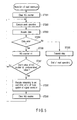
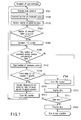
- FIGS. 4 and 5 are flowcharts showing various kinds of control by the control unit 9. More specifically, FIG. 4 is a flowchart showing processing for learning the characteristic of the signal corrector 5 of the focus servo in disk insertion. FIG. 5 is a flowchart showing readjustment processing on condition that no data can be read out from the disk.
- preparation steps (ST101 and ST103) are executed such that data can be read out from and written on the disk.
- the control unit 9 instructs the setting learning unit 7 to start learning.
- the setting learning unit 7 learns an optimum characteristic of the focus system of the signal corrector 5 (ST102).
- Signal amplification/attenuation data obtained by learning is stored in the correction data storage unit 8.
- the control unit 9 manages the count value by an NG counter. As shown in FIG. 5, upon receiving a read command, the control unit 9 clears the NG counter (ST201) and executes a seek operation (ST202). Next to the seek operation, data to be read out is read out from the target address position (ST203). The data to be read out is read through the optical pickup 2. The control unit 9 determines whether the readout data is an error (ST204). If the readout data is no error (YES in step ST204), the data is transmitted (ST205), and the read operation is ended.
- the control unit 9 increments the NG counter (ST206).
- the control unit 9 refers to the NG counter. If the value is smaller than a predetermined value (NO in step ST207), the seek operation is repeated (ST202). If the NG counter is equal to or larger than the predetermined value (YES in step ST207), the setting of the focus system of the signal corrector 5 is relearned (ST208). More specifically, the control unit 9 activates the setting learning unit 7. After that, the control unit 9 clears the NG counter (ST209) and returns to the seek operation (ST202).
- the characteristic of the focus servo of the signal corrector 5 is relearned and corrected to the optimum value at that time. Accordingly, the read after relearning can successfully be executed.
- a control unit 9 has a function of detecting the operation state of each unit in the optical disk drive or giving operation specifications to the units and designates the operation timing of a setting learning unit 7.
- preparation steps (ST301 and ST303) are executed such that data can be read out from and written on the disk.
- the control unit 9 instructs the setting learning unit 7 to start learning.
- the setting learning unit 7 learns the optimum characteristic of the focus system of a signal corrector 5 (ST302).
- Signal amplification/attenuation data obtained by learning is stored in a correction data storage unit 8.
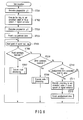
- the control unit 9 clears the processed sector count (to be described later) and two variables of an NG counter (ST304).
- the control unit 9 upon receiving a read command, executes a seek operation (ST401) to move an optical pickup 2 to a readable position of the target sector. After the end of the seek operation, the control unit 9 counts the number of data every time the data in the target sector is received (ST402), and monitors the number of correction bytes (ST403).
- the number of correction bytes is an effective index in the read of CD media. In a read of DVD media, the number of correction lines is used instead.
- the control unit 9 checks whether the number of correction bytes is equal to or larger than a specific value (ST404). If the number of correction bytes is equal to or larger than the specific value (YES in step SST404), the control unit 9 clears the NG counter (ST405). If the number of correction bytes is smaller than the specific value (NO in step ST404), the NG counter need not be incremented.
- the control unit 9 also checks the number of processed sectors (ST406). If the number of processed sectors has not reached a predetermined value (NO in step ST406), data is acquired (ST410). If the number of processed sectors has reached the predetermined value (YES in step ST406), the number of processed sectors is cleared to prepare for the next check (ST407).
- control unit 9 checks whether the value of the NG counter is equal to or larger than a specific value (ST408). If the value of the NG counter is smaller than the specific value (NO in step ST408), the data read quality from the optical disk is not poor. The NG counter is cleared to prepare for the next check (ST409), and data is acquired (ST410). After the data is acquired, the control unit 9 checks whether the acquired data contains an error (ST411). If the acquired data contains an error (YES in step ST411), the processing is repeated from the seek operation (ST401). If the acquired data contains no error (NO in step ST411), i.e., if the data is normal, the data is transmitted (ST412), and the read operation is ended.
- control unit 9 instructs the setting learning unit 7 to relearn the setting of the focus system of the signal corrector 5 (ST413). After that, the control unit 9 clears the NG counter to prepare for the next measurement (ST414) and returns to the seek operation (ST401).
- the second embodiment a sign indicating that readout data should become uncorrectable is detected in advance, and the setting of the focus system of the signal corrector 5 is relearned. Accordingly, the same stable read and write performance as in the first embodiment can be obtained while preventing any data unreadable state.
- a control unit 9 has a function of detecting the operation state of each unit in the optical disk drive or giving operation specifications to the units and designates the operation timing of a setting learning unit 7.
- preparation steps (ST501 and ST503) are executed such that data can be read out from and written on the disk.
- the control unit 9 instructs the setting learning unit 7 to start learning.
- the setting learning unit 7 learns an optimum characteristic of the focus system of a signal corrector 5 (ST502).
- Signal amplification/attenuation data obtained by learning is stored in a correction data storage unit 8.
- the control unit 9 resets the unadjustment time as an internal variable (ST504). This is a timer variable that measures the time that has elapsed from the reset time.
- the optical disk drive is set in a state wherein it can receive a read or write command.
- the control unit 9 starts an event wait loop (ST505).
- step ST506 when a read command is received (YES in step ST506), read processing is executed (ST507).
- write processing is executed (ST509).
- the control unit 9 monitors whether the unadjustment time exceeds a specific value (ST510). If the unadjustment time exceeds the specific value (YES in step ST510), the setting of the focus system of the signal corrector 5 is relearned (ST511), and the unadjustment time is reset to prepare for the next learning (ST512).
- the setting of the focus system of the signal corrector 5 is relearned especially by using the read/write command nonreception time, i.e., idle time.
- the optical disk drive can always keep the focus system of the signal corrector 5 in an optimum state without impeding read or write command processing.
- the read or write commands may continuously be processed at a shifted optimum point.
- the third embodiment is preferably implemented in combination with the first or second embodiment.
- a control unit 9 has a function of detecting the operation state of each unit in the optical disk drive or giving operation specifications to the units and designates the operation timing of a setting learning unit 7.
- preparation steps (ST601 and ST603) are executed such that data can be read out from and written on the disk.
- the control unit 9 instructs the setting learning unit 7 to start learning.
- the setting learning unit 7 learns an optimum characteristic of the focus system of a signal corrector 5 (ST602).
- Signal amplification/attenuation data obtained by learning is stored in a correction data storage unit 8.
- the control unit 9 resets an idle timer which is managed by the control unit 9 (ST604).
- the optical disk drive is set in a state wherein it can receive a read or write command.
- the control unit 9 starts an event wait loop (ST605).
- the control unit 9 waits for a command from the host computer. Upon receiving a read command (YES in step ST606), the control unit 9 checks whether a spindle motor 1 is at a standstill (ST607). If it is determined that the spindle motor 1 is at a standstill (YES in step ST607), the spindle motor 1 is activated (ST608). After that, the control unit 9 instructs the setting learning unit 7 to relearn the setting of the focus system of the signal corrector 5 (ST609). After that, read processing is executed (ST610). In the read processing, an optical pickup 2 seeks the target position, and data is acquired from the optical disk. If the acquired data is an error, seek is executed again. If normal data is acquired by seek, the normal data is transmitted to the host. After the read processing, the control unit 9 resets the idle timer (ST611) and returns to the event wait loop to prepare for the next event (ST605).
- the control unit 9 Upon receiving a write command (YES in step ST612), the control unit 9 checks whether the spindle motor 1 is at a standstill (ST613). If it is determined that the spindle motor 1 is at a standstill (YES in step ST613), the spindle motor 1 is activated (ST614). After that, the control unit 9 instructs the setting learning unit 7 to relearn the setting of the focus system of the signal corrector 5 (ST615). After that, write processing is executed (ST616). In the write processing, write data from the host computer is received, OPC learning is executed as needed, the optical pickup 2 is moved to the target write position, and the optical pickup 2 writes the data on the optical disk. After the write processing, the control unit 9 resets the idle timer (ST611) and returns to the event wait loop to prepare for the next event (ST605).
- the control unit 9 stops the spindle motor 1 (ST619). If the spindle motor 1 is already at a standstill (YES in step ST618), the spindle motor is not stopped again. In either case, the control unit 9 resets the idle timer (ST611) and returns to the event wait loop (ST605).
- the spindle motor 1 when the count time by the idle timer has reached a predetermined time, the spindle motor 1 is stopped. If a read or write is to be executed since then, the spindle motor 1 is activated. Subsequently, the setting of the focus system of the signal corrector 5 is relearned.
- the control unit 9 executes relearning of the setting of the focus system of the signal corrector 5 at the activation timing of the spindle motor 1.
- the spindle motor 1 is often continuously be at a standstill for a long time. During that time, the temperature can largely change. According to the fourth embodiment, even in this case, the settling of the focus system of the signal corrector 5 can be kept in an optimum state.
- a control unit 9 has a function of detecting the operation state of each unit in the optical disk drive or giving operation specifications to the units and designates the operation timing of a setting learning unit 7.
- preparation steps (ST701 and ST703) are executed such that data can be read out from and written on the disk.
- the control unit 9 instructs the setting learning unit 7 to start learning.
- the setting learning unit 7 learns an optimum characteristic of the focus system of a signal corrector 5 (ST702).
- Signal amplification/attenuation data obtained by learning is stored in a correction data storage unit 8.
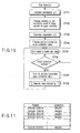
- the control unit 9 prepares a position/correction value correspondence table (ST704). Actually, the position/correction value correspondence table is prepared (stored) in the correction data storage unit 8.
- FIG. 11 is a view showing an example of the position/correction value correspondence table.
- Positions in the position/correction value correspondence table are defined by dividing the sector addresses in the disk into appropriate areas and permanently given to the disk.
- Correction values in the position/correction value correspondence table are obtained by the learning step (ST702). That is, in the learning step (ST702), the position/correction value correspondence table is generated on the basis of the correction values obtained from the respective positions (ST704).
- the control unit 9 When the position/correction value correspondence table is generated (ST704), the control unit 9 starts an event wait loop (ST705). Upon receiving a read command in the event wait loop (YES in step ST706), the control unit 9 refers to the position/correction value correspondence table (ST707), obtains a correction value corresponding to the read target address from the position/correction value correspondence table, and executes read processing (ST708).
- FIG. 12 is a flowchart showing read processing (ST708).
- the control unit 9 upon receiving a read command, the control unit 9 first clears an NG counter (ST801) and executes a seek operation (ST802). Next to the seek operation, data to be read out is read out from the target address position (ST803). The data to be read out is read through an optical pickup 2. The control unit 9 determines whether the readout data is an error (ST804). If the readout data is no error (YES in step ST804), the data is transmitted (ST805), and the read operation is ended.
- the control unit 9 increments the NG counter (ST806).
- the control unit 9 refers to the NG counter. If the value is smaller than a predetermined value (NO in step ST807), the seek operation is repeated (ST802). If the NG counter is equal to or larger than the predetermined value (YES in step ST807), the setting of the focus system of the signal corrector 5 is relearned (ST808). More specifically, the control unit 9 activates the setting learning unit 7. By this relearning, a position/correction value correspondence table is generated on the basis of correction values obtained from the respective positions and stored in the correction data storage unit 8 (ST809). After that, the control unit 9 clears the NG counter (ST810) and returns to the seek operation (ST802).
- a satisfactory correction value can be given to, e.g., a largely warped disk for which the optimum set value of the focus system of the signal corrector 5 changes for each position on the disk. Hence, satisfactory read performance can always be obtained on the entire surface of the disk.
- the servo system set value is readjusted by a predetermined trigger (at a predetermined timing).
- occurrence of an error in read data is used as a trigger. That is, it is determined whether read data is normal.
- the servo system set value is readjusted on the basis of the determination result.
- the number of correction bytes of read data is used as a trigger. That is, it is determined whether the number of correction bytes or the number of correction lines in acquiring read data is equal to or larger than a specific value.
- the servo system set value is readjusted on the basis of the determination result.
- an idle state is used as a trigger. That is, it is determined whether neither a read command nor a write command are generated and whether a predetermined time has elapsed from the preceding readjustment.
- the servo system set value is readjusted on the basis of the determination results.
- return from a standby state is used as a trigger. That is, when the spindle motor which has been at a standstill is reactivated, or the spindle motor is reactivated for the purpose of a read or write, the servo system set value is readjusted.
- a disk radial position is used as a trigger. That is, when data is to be read out for a predetermined radial position on a disk, the position/correction value correspondence table is referred to, and the servo system set value is readjusted on the basis of a correction value corresponding to the radial position. In addition, the position/correction value correspondence table is updated to latest information as needed.
- the object to be adjusted is a correction value set for the servo system in advance and, more particularly, a correction value of the focus system.
- a correction value set for the tracking system may be adjusted.
- a correction value set in advance to adjust the amplitude of an RF signal as a data signal may be adjusted.
- an adjustment value such as an offset given to the actuator or the like in advance may be adjusted.
- Various values as described above can be readjusted by the above-described trigger (at a predetermined timing).
- learning of the focus servo characteristic, tracking servo characteristic, RF signal characteristic, and actuator offset adjustment value is appropriately executed for a physical device whose characteristics change during the operation, thereby achieving optimum signal correction. Accordingly, stable read and write performance can be implemented throughout the operation period.
- the position of the optical pickup is mechanically corrected in the focus direction, or an electrical offset is added to the focus actuator to help focusing of the focus servo.
- the present invention is combined with the correction amount learning function, it is possible to cope with even a change-over-time in warping of the inserted disk.
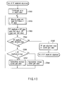
- RF signal amplitude adjustment will be described with reference to FIG. 13.
- an appropriate RF signal amplifier gain value is given as a current gain value to the signal corrector 5 which functions as an RF amplifier (ST901).
- the RF signal is expected to have a measurable amplitude.
- the upper and lower limit values of the RF signal are obtained on the basis of the current gain value (ST902).
- An RF signal is obtained by converting reflected light of a laser beam from a track in a tracking state into an electrical signal, integrating the magnitude of the signal, and removing the DC component through an LPF. Since the DC component is removed, the RF signal exhibits complex movement while uniformly varying from 0 [V] in the vertical direction. This is measured for a predetermined period. The maximum and minimum values are obtained as the upper and lower limit values of the RF signal.
- the RF amplitude is obtained.
- the RF amplitude can be obtained by RF signal upper limit value - RF signal lower limit value (ST903).
- ST904 it is checked whether the obtained RF amplitude falls within the allowable range (ST904). If the RF amplitude falls within the allowable range (YES in step ST904), the current gain value is employed as the RF gain adjustment value, and the processing is ended (ST905). If the RF amplitude falls outside the allowable range (NO in step ST904), it is checked whether the RF amplitude is too large (ST906).
- step ST906 If the RF amplitude is too large (YES in step ST906), the gain of the RF signal amplifier, i.e., the current gain value is appropriately decreased (ST907). If the RF amplitude is too small (NO in step ST906), the gain of the RF signal amplifier, i.e., the current gain value is appropriately increased (ST908).
- the value may be increased or decreased by a fixed amount.
- convergence may be accelerated by using the substantial proportional relationship between the amplifier gain value and the RF amplitude value.
- the upper and lower limit values of the RF amplitude are measured again (ST902).
- the RF gain adjustment value set in the above-described way is readjusted by the above-described trigger (at a predetermined timing). Accordingly, stable read performance can be implemented.
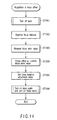
- a focus offset means the DC component of a focus error signal.
- the servo circuit 6 can execute servo control only after removing the DC current of the focus error signal. To obtain a focus offset, first, the laser is turned off (ST1001). Accordingly, incident light on the photodetection element is almost zero.
- the focus balance adjustment value is invalidated to equalize the focus balance in the positive and negative directions (ST1002). Then, the focus error value is measured (ST1003).
- the focus error value measured at this time coincides with the DC component of the focus error signal. The measured value is recorded as the focus offset (ST1004).
- step ST1005 the focus balance adjustment value is restored (ST1005).
- the laser is turned on again, and the focus servo is turned on (ST1006).
- the focus offset obtained in step ST1004 is subtracted from the focus error signal.
- a tracking offset can also be acquired by the same method as described above.
- the focus balance adjustment value set in the above-described way is readjusted by the above-described trigger (at a predetermined timing). Accordingly, stable read performance can be implemented.
- the preset correction values or adjustment values are readjusted in both the read step of reading data from the optical disk and the write step of writing data on the disk.
- the preset correction values or adjustment values may be readjusted only in the read step.
- an optical disk apparatus capable of, e.g., executing signal processing following a change in characteristic of an optical pickup or optical disk can be provided.
Landscapes
- Optical Recording Or Reproduction (AREA)
Applications Claiming Priority (2)
| Application Number | Priority Date | Filing Date | Title |
|---|---|---|---|
| JP2003367837 | 2003-10-28 | ||
| JP2003367837A JP2005135460A (ja) | 2003-10-28 | 2003-10-28 | 光ディスク装置 |
Publications (2)
| Publication Number | Publication Date |
|---|---|
| EP1528544A2 true EP1528544A2 (fr) | 2005-05-04 |
| EP1528544A3 EP1528544A3 (fr) | 2007-09-05 |
Family
ID=34420141
Family Applications (1)
| Application Number | Title | Priority Date | Filing Date |
|---|---|---|---|
| EP04019616A Withdrawn EP1528544A3 (fr) | 2003-10-28 | 2004-08-18 | Appareil de disque optique |
Country Status (4)
| Country | Link |
|---|---|
| US (1) | US20050088932A1 (fr) |
| EP (1) | EP1528544A3 (fr) |
| JP (1) | JP2005135460A (fr) |
| CN (1) | CN1299277C (fr) |
Families Citing this family (3)
| Publication number | Priority date | Publication date | Assignee | Title |
|---|---|---|---|---|
| JP2005166080A (ja) * | 2003-11-28 | 2005-06-23 | Matsushita Electric Ind Co Ltd | 光ディスク装置 |
| JP4476225B2 (ja) * | 2006-02-21 | 2010-06-09 | パナソニック株式会社 | 光ディスク装置、トラッキング制御方法、及び集積回路 |
| CN121909019A (zh) | 2023-09-27 | 2026-04-21 | Viiv保健英国第三有限公司 | 药物组合物 |
Family Cites Families (9)
| Publication number | Priority date | Publication date | Assignee | Title |
|---|---|---|---|---|
| JP3039343B2 (ja) * | 1995-11-17 | 2000-05-08 | 日本ビクター株式会社 | 光ディスク再生装置及び光ディスク再生装置のサ−ボ制御の最適化方法 |
| JPH08306054A (ja) * | 1995-04-28 | 1996-11-22 | Sony Corp | トラッキングサーボ回路 |
| JPH097195A (ja) * | 1995-06-15 | 1997-01-10 | Fujitsu Ltd | 焦点制御方法及び光ディスク装置 |
| JP3442984B2 (ja) * | 1997-12-26 | 2003-09-02 | シャープ株式会社 | 光ピックアップの位置制御装置 |
| JP2000057590A (ja) * | 1998-08-07 | 2000-02-25 | Alpine Electronics Inc | ディスク再生装置 |
| JP2002109772A (ja) * | 2000-09-29 | 2002-04-12 | Sanyo Electric Co Ltd | 光ディスク装置 |
| WO2002059888A2 (fr) * | 2001-01-25 | 2002-08-01 | Dphi Acquisitions, Inc | Lecteur de disque optique a servosysteme numerique de poursuite et de mise au point |
| JP2003109232A (ja) * | 2001-09-28 | 2003-04-11 | Sanyo Electric Co Ltd | 光ディスク再生装置に用いられるサーボ回路及びそのサーボ方法 |
| JP2003248940A (ja) * | 2002-02-21 | 2003-09-05 | Funai Electric Co Ltd | 光ディスク装置 |
-
2003
- 2003-10-28 JP JP2003367837A patent/JP2005135460A/ja active Pending
-
2004
- 2004-08-18 EP EP04019616A patent/EP1528544A3/fr not_active Withdrawn
- 2004-09-03 CN CNB2004100686277A patent/CN1299277C/zh not_active Expired - Fee Related
- 2004-09-13 US US10/938,560 patent/US20050088932A1/en not_active Abandoned
Also Published As
| Publication number | Publication date |
|---|---|
| CN1612238A (zh) | 2005-05-04 |
| EP1528544A3 (fr) | 2007-09-05 |
| US20050088932A1 (en) | 2005-04-28 |
| JP2005135460A (ja) | 2005-05-26 |
| CN1299277C (zh) | 2007-02-07 |
Similar Documents
| Publication | Publication Date | Title |
|---|---|---|
| CN1299277C (zh) | 光盘装置 | |
| JP3565275B2 (ja) | フォーカスサーチ方法 | |
| WO2003050512A1 (fr) | Procede et appareil assurant un controle adaptatif de la servo-piste | |
| JP4725538B2 (ja) | 光ディスク装置 | |
| KR100718428B1 (ko) | 광디스크의 틸트 서보 제어 방법 | |
| CN101174432B (zh) | 刻录策略控制方法及信息刻录装置 | |
| JP2000357338A (ja) | 記録媒体駆動装置及びチルト検出方法 | |
| CN1348175A (zh) | 记录和重放设备、记录和重放方法以及记录介质 | |
| JPH0991713A (ja) | 光学的情報記録再生装置 | |
| CN1568508A (zh) | 光盘装置 | |
| US8027239B2 (en) | Data recording and reproducing device, camera device, and data recording and reproducing method | |
| TWI238402B (en) | Focus position adjustment method and system thereof | |
| JP2007234144A (ja) | 光ディスク装置 | |
| CN101727929B (zh) | 光盘装置 | |
| JP3985113B2 (ja) | 光ディスク装置の調整方法 | |
| CN100474406C (zh) | 光盘读取/存储系统聚焦偏差设定方法 | |
| KR100718432B1 (ko) | 광디스크 기록 및 재생 시스템의 포커스 서보 제어 방법 | |
| JPH11232677A (ja) | 光ディスク装置 | |
| US20060158975A1 (en) | Optical pickup tilt correction control unit and tilt correcting method | |
| JP2005174387A (ja) | 光ディスク記録再生装置のチルト制御方法 | |
| JP2004199779A (ja) | 光ディスク記録再生装置のチルト制御方法 | |
| CN1981333A (zh) | 光盘装置及信号形成方法 | |
| JP2005166191A (ja) | 光ディスク記録再生装置のチルト制御方法 | |
| JP2005166192A (ja) | 光ディスク記録再生装置のチルト制御方法 | |
| JP2006179096A (ja) | 光ディスク装置 |
Legal Events
| Date | Code | Title | Description |
|---|---|---|---|
| PUAI | Public reference made under article 153(3) epc to a published international application that has entered the european phase |
Free format text: ORIGINAL CODE: 0009012 |
|
| 17P | Request for examination filed |
Effective date: 20040818 |
|
| AK | Designated contracting states |
Kind code of ref document: A2 Designated state(s): AT BE BG CH CY CZ DE DK EE ES FI FR GB GR HU IE IT LI LU MC NL PL PT RO SE SI SK TR |
|
| AX | Request for extension of the european patent |
Extension state: AL HR LT LV MK |
|
| PUAL | Search report despatched |
Free format text: ORIGINAL CODE: 0009013 |
|
| AK | Designated contracting states |
Kind code of ref document: A3 Designated state(s): AT BE BG CH CY CZ DE DK EE ES FI FR GB GR HU IE IT LI LU MC NL PL PT RO SE SI SK TR |
|
| AX | Request for extension of the european patent |
Extension state: AL HR LT LV MK |
|
| 17Q | First examination report despatched |
Effective date: 20071214 |
|
| AKX | Designation fees paid |
Designated state(s): DE FR GB |
|
| STAA | Information on the status of an ep patent application or granted ep patent |
Free format text: STATUS: THE APPLICATION IS DEEMED TO BE WITHDRAWN |
|
| 18D | Application deemed to be withdrawn |
Effective date: 20080425 |