EP1528330B1 - Baueinheit für eine Kompaktheizungsanlage - Google Patents
Baueinheit für eine Kompaktheizungsanlage Download PDFInfo
- Publication number
- EP1528330B1 EP1528330B1 EP03025084A EP03025084A EP1528330B1 EP 1528330 B1 EP1528330 B1 EP 1528330B1 EP 03025084 A EP03025084 A EP 03025084A EP 03025084 A EP03025084 A EP 03025084A EP 1528330 B1 EP1528330 B1 EP 1528330B1
- Authority
- EP
- European Patent Office
- Prior art keywords
- construction unit
- insert
- channel
- unit according
- valve
- Prior art date
- Legal status (The legal status is an assumption and is not a legal conclusion. Google has not performed a legal analysis and makes no representation as to the accuracy of the status listed.)
- Expired - Lifetime
Links
Images


Classifications
-
- F—MECHANICAL ENGINEERING; LIGHTING; HEATING; WEAPONS; BLASTING
- F24—HEATING; RANGES; VENTILATING
- F24H—FLUID HEATERS, e.g. WATER OR AIR HEATERS, HAVING HEAT-GENERATING MEANS, e.g. HEAT PUMPS, IN GENERAL
- F24H9/00—Details
- F24H9/14—Arrangements for connecting different sections, e.g. in water heaters
-
- F—MECHANICAL ENGINEERING; LIGHTING; HEATING; WEAPONS; BLASTING
- F24—HEATING; RANGES; VENTILATING
- F24D—DOMESTIC- OR SPACE-HEATING SYSTEMS, e.g. CENTRAL HEATING SYSTEMS; DOMESTIC HOT-WATER SUPPLY SYSTEMS; ELEMENTS OR COMPONENTS THEREFOR
- F24D3/00—Hot-water central heating systems
- F24D3/08—Hot-water central heating systems in combination with systems for domestic hot-water supply
-
- F—MECHANICAL ENGINEERING; LIGHTING; HEATING; WEAPONS; BLASTING
- F24—HEATING; RANGES; VENTILATING
- F24H—FLUID HEATERS, e.g. WATER OR AIR HEATERS, HAVING HEAT-GENERATING MEANS, e.g. HEAT PUMPS, IN GENERAL
- F24H1/00—Water heaters, e.g. boilers, continuous-flow heaters or water-storage heaters
- F24H1/48—Water heaters for central heating incorporating heaters for domestic water
- F24H1/52—Water heaters for central heating incorporating heaters for domestic water incorporating heat exchangers for domestic water
-
- F—MECHANICAL ENGINEERING; LIGHTING; HEATING; WEAPONS; BLASTING
- F24—HEATING; RANGES; VENTILATING
- F24H—FLUID HEATERS, e.g. WATER OR AIR HEATERS, HAVING HEAT-GENERATING MEANS, e.g. HEAT PUMPS, IN GENERAL
- F24H9/00—Details
- F24H9/14—Arrangements for connecting different sections, e.g. in water heaters
- F24H9/142—Connecting hydraulic components
Definitions
- the invention relates to a structural unit for a compact heating system.
- Such units are state of the art and are used if possible to take all the fittings of such a heating system in a tight space and provide the necessary channel connections and line connections. This is not only a compact design to be achieved, but beyond both the manufacturing and assembly costs and the subsequent maintenance costs are reduced.
- a unit for a compact heating system which has two heating circuits, one for heating the heating water for the central heating and another for heating the service water.
- the structural unit described therein is comparatively compact and essentially composed of three injection-molded parts, of which the first centrally arranged forms the pump housing, which is designed to be open at the front for receiving the motor assembly, and form the two other fitting housings adjoining on both sides.
- the present invention has the object to further improve such a unit, in particular to increase the functionality and thus simplify installation and maintenance on.
- the invention provides a unit for a compact heating system, which has rear connections for a plate heat exchanger, a central pump housing or pump housing component, connect to the valve body on both sides, wherein the pump housing for receiving the impeller and for connecting the electric motor is designed to be open at the front.
- a front accessible plug-in space is provided, which serves to accommodate at least one valve.
- these insertion spaces each form a connection base for a connecting piece of the heating system, a channel leading to the plate heat exchanger and at least one further channel or connection.
- the basic idea of the present invention is to form a connection base for the lines to be connected or connected by the two laterally adjoining the pump housing fitting housing with their insertion spaces and at the same time to receive the necessary fittings, by means of the front accessible plug-in spaces, so that a change of fittings even when installed easily possible.
- the plate heat exchanger connects the side fitting housing, so that the pump housing can be incorporated form-fitting between this fitting housing.
- Such a structural unit can, as will be described in detail below, preferably be formed from three injection-molded parts which can be produced exclusively by means of drawing cores, that is to say without melting cores, which is advantageous in terms of production technology.
- Armature according to the present invention are not only valves or other switching elements, this may also be components such as air or dirt separators or parts thereof or, for example, a closure cap for a control opening.
- the insertion spaces are arranged relative to the paired connection pieces for the plate heat exchanger so that they overlap one connection in the insertion direction, so that no separate transverse channel is required for the connection between the insertion space and connection piece of the plate heat exchanger.
- the insertion spaces are each connected to the bottom side with a channel leading to the plate heat exchanger channel through an opening in the ground, wherein this channel extends in the direction of insertion and to the connecting piece of the heat exchanger.
- insertion space and channel can each be formed by coming from the front or from the rear of the drawing cores in the tool, wherein the pulling core for the channel is also used for the connection piece.
- both fitting housing have a downwardly directed channel to a connecting piece for the heating flow or the heating return, which adjoins the insertion space.
- the insertion spaces each have a circular cross-section and are arranged with their longitudinal axes substantially parallel to the axis of rotation of the centrifugal wheel. Then the fittings / inserts to be incorporated into the drawer spaces can also be used from the front when mounted. Due to the round cross-section, a simple seal, for example with O-rings, is possible. In addition, bayonet or screw can be realized, which make it necessary to rotate a valve in the insertion space.
- One of the insertion spaces is advantageously provided for receiving a switching valve, in particular a 3/2-way valve, which is preferably inserted as a plug-in module from the front into the insertion space.
- the insertion unit expediently not only the valve body, but also the sealing seats, so that in the case of a defect or during maintenance, all the essential parts of the switching valve forward together with the plug-in unit can be pulled out and overhauled or replaced.
- the insertion space in the region of the switching valve has corresponding channel connections for the three channels to be alternately connected in pairs.
- the switching valve controls the heating water flow coming from the primary heat exchanger either in the heating network or in a secondary heat exchanger, typically a plate heat exchanger.
- the control takes place in dependence of the hot water flow, for which appropriate sensors and control electronics are provided.
- the valve is actuated by appropriate actuating means, preferably by electric motor.
- valve body transverse to the insertion direction for the changeover valve a further, preferably accessible from above insertion space provided for the integration of the control means, in particular the electric motor is provided.
- the valve-near arrangement of the motor at the top is particularly favorable in terms of mechanical power transmission and has the advantage that the motor can be pulled up out of the insertion space in order to maintain or replace it, for example. Since there is typically a certain amount of free space above the unit, this positioning is therefore particularly favorable and easily accessible, ie. H. Both valve and motor can be replaced without having to remove the assembly.
- This channel which is then controlled by the changeover valve, leads down to a connecting piece for the heating flow.
- This connection piece for connection to the stationary lines on the underside of the unit is particularly favorable, since the lines are routinely routinely installed in the floor or baseboard area, especially when retrofitting the heating system, as is common in old buildings and therefore come from below. The connection of these lines is therefore simplified, in particular because of the good accessibility of the line connections in this area of the compact heating system.
- bypass channel connects, which preferably extends parallel to the insertion direction under the valve-side insertion space to the rear and there opens into a leading to the suction side of the pump transverse channel.
- bypass channel does not short-circuit the pump hydraulically, it is regularly necessary to use a control valve.
- This is advantageously used from the back of the channel and set by the expert in the installation of the system.
- this arrangement is favorable because the valve can be incorporated into the drawing core opening required anyway for the channel.
- this arrangement also offers considerable advantages, in particular during operation of the system. It not only increases the compactness of the unit, but also ensures that in the installed state, the control valve is not accessible, so not accidentally manipulated by an operator can be, but only targeted by the professional installation or removal of the unit.
- a channel with line connection for leading to the primary heat exchanger line connects, preferably transversely to the insertion direction and on the side facing away from the pump side of the Armaturengehöuses. This coming from the primary heat exchanger line is connected by the switching valve either with the input line to the secondary heat exchanger (plate heat exchanger) or the heating flow.
- the primary heat exchanger is typically located in the upper area of the compact heating system, ie above the unit and its lines lead laterally down to the unit, it is also particularly advantageous montagetechnisch to provide this connection seen from the front on the left side of the valve-side fitting housing, since then namely a connection of the conduit usually formed from a substantially rigid tube is easy to accomplish.
- each of the fitting housing a frontally accessible insertion space is provided, it is expedient to complete the insertion spaces by bayonet connections by means of a lid or the insertable fitting therein, so that an exchange of valves or the Access to the drawer spaces is quick and easy.
- identical bayonets are preferably used for both insertion spaces, so that identical seals and the same cover or fitting connections can be used.
- the other insertion space is provided and designed to receive a dirt separator. Then, after opening the lid of the insertion space of the dirt and so that the dirt collected therein are removed or is at least accessible to remove any deposits therein. It also needs no separate installation space for a dirt separator can be provided.
- the insertion space is dimensioned correspondingly large in order to ensure a sufficient effective flow cross-section despite the Abscheider füren flow cross-section reduction.
- the dirt separator is therefore advantageously incorporated as a sieve-like insert in the insertion space, which is removable from the front after removing a lid. In the lid of the insertion space further fittings or sensors can be incorporated.
- a safety valve is incorporated in the cover, which releases a connection to the outside atmosphere when a predetermined pressure is exceeded, or a channel connection into a drain or a collecting vessel.
- the arrangement of the valve in the lid this can be quickly replaced, checked and cleaned, it also takes up the least possible installation space within the unit.
- the lid is advantageously integrally formed with a component of the integrated in the lid fitting, in particular the safety valve and as a plastic injection molded part.
- the lid can thus simultaneously form cover function and, for example, housing function for the safety valve.
- the dirt separator side slide housing forms according to the invention, a connection base as explained above.
- it has two lateral connections for a heat storage for storing heated heating water, which are channel-separated by a einliederbore partition.
- the arrangement is chosen so that the integration of the partition the lateral connections the Heat storage in series with the coming out of the plate heat exchanger power to the primary heat exchanger. If, on the other hand, the assembly is to be used without heat storage, then only the lateral connections are to be closed. By then not incorporated dividing wall, the plug-in housing is freely continuous in the axial direction. This design variant thus allows the same tool to produce a unit both for compact heating systems with as well as for those without heat storage.
- the poor Schmutzabscheider simplyen fitting housing vertically downwardly directed channel to the Anchlussstutzen for the heating return.
- a connection for integrating a sensor is provided on the insertion space provided for the dirt separator, preferably on the upper side.
- This sensor connection advantageously also has a bayonet connection, so that the sensor can be exchanged quickly and without tools.
- a lateral connection is provided on the channel arranged between plug-in housing and connecting piece for the heating return, which can be locked by means of a valve.
- the compact heating system can then be emptied in the installed state via this lateral connection or filled by connecting a corresponding pressure line.
- the invention also has the Schmutzabscheider made.
- Insertion space on a bottom-side opening which a fluid-conducting connection to a running in the direction of insertion channel forms a connection piece for the plate heat exchanger.
- a direct channel connection to the connecting piece for the plate heat exchanger is formed, which can be formed by a simple pulling core in the tool.
- the axes of the insertion space and the channel are arranged parallel to one another and the cross-sections of the insertion space and the channel overlap (as viewed in the insertion direction).
- the dirt separator on the insertion space preferably in the bottom region of a leading to the suction side of the pump channel.
- Einschubraums as a connection base further increased also can be formed on a comparatively short way the required connection channel to the suction nozzle of the pump, which is located immediately adjacent to the dirt separator side valve body. Since both the valve body and the pump housing or this receiving injection molding component are manufactured as separate injection molded parts, which are joined only during assembly, these transverse channels can also be advantageously realized by drawing cores in the injection mold, without costly melting cores are required.
- the unit is designed so that not only for the heating flow and the heating return downwardly directed connection piece are provided on the underside of the unit, but also the two other connections for the hot water supply and coming from the compact heating system heated hot water are provided on the bottom.
- it is expediently provided all four connecting pieces for the heating circuit and the service water supply to the underside of the unit, so that it can be connected to the stationary stationary lines with little maintenance.
- connections are advantageously arranged so that they are all in a horizontal plane. Then, namely, the unit, when the downward outgoing terminals are designed as plug-in connections, are connected by lowering down to the stationary lines, which can serve for sealing simple O-rings, as in connection connections of such units in the rest of the prior art counts.
- these known in building units connectors are each positively secured by an approximately U-shaped bracket, which is postponed after joining the lines by joining transversely to the terminal.
- this positive locking advantageously by a central closure plate, d. H. in that, after lowering downwards, the assembly unit is completely connected by inserting the central closure plate without the need for further assembly work.
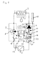
- Fig. 1 shown compact heating system is a gas boiler, as it is typically intended for wall mounting as a compact device for heat supply working with radiators space heating and for hot water / hot water production.
- a burner 1 acts on a primary heat exchanger 2, the heated water of a heat exchanger 3, typically in the form of one or more radiators for space heating, is supplied.
- the cooled water flows from the heat exchanger 3 back to the primary heat exchanger 2 and is circulated by means of a arranged on the cold side of the heat exchanger 2, 3 circulation pump 4.
- a plate heat exchanger 5 is provided, in which the coming from the water network cold hot water is heated. Since the heating of the service water has to take place only in Ent Cyprusfall, appropriate sensors, in particular a flow meter 6 as well as a pressure and temperature sensor 7 is provided, depending on the output signal of a servomotor 8 is driven, which drives a 3/2-way valve 9, in order to control the heating of domestic hot water coming from the primary heat exchanger 2 heat-conducting liquid flow instead of the heat exchanger 3 to the plate heat exchanger 5.
- a surge tank 10 is provided and a heat storage 11, which is connected in series between plate heat exchanger 5 and the primary heat exchanger 2, here on the cold side.
- Fig. 1 with 3 symbolized heat exchanger is, as usual today in hot water heating systems, provided with a thermostatic valve 12, which controls the circuit in terms of flow resistance and then, if no heat demand is given locks.
- a bypass line 13 is provided within the compact heating system with a valve 14, via which the hydraulically effective line cross section of the bypass line 13 is adjustable. Through this bypass line 13, a closed circulation circuit is ensured, even if the thermostatic valve 12 is fully closed.
- a safety valve 15 in the form of a pressure relief valve suction side of the pump 4 are provided and two shut-off valves 16 and 17, which are connected via a line 18 to each other.
- the heating system has a total of four line connections in the form of plug connections, namely a connection 19 for the heating flow as a port 20 for the heating return. Furthermore, a connection 21 is provided for the service water inlet and a connection 22 for the coming from the plant hot water.
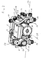
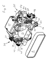
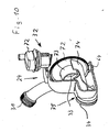
- FIG. 1 framed by broken lines part of the compact heating system is formed by a structural unit 23, the structure of the basis of FIGS. 2 to 9 is shown in detail.
- the assembly 23 is essentially composed of three injection-molded parts, namely a central, the pump housing-containing pump housing component 24, to the left in installation position seen from the front left a dashboard housing 25 and the right side a fitting housing 26.
- the components 24, 25 and 26 are manufactured as plastic injection molded components and designed to be without use of fused cores, ie with comparatively inexpensive tools that work with drawing cores can be produced.
- These components 24 to 26 are incorporated into each other in the transverse direction 27 to the impeller axis 28 of the pump and are positively secured by the rear-connected plate heat exchanger 5 in this position.
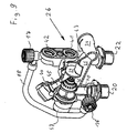
- the pump housing component 24 has the actual pump housing and a forwardly open insertion space 29, which is provided for receiving the pump impeller and for flanging the forward adjoining motor 30.
- the pump housing has an obliquely right above outgoing discharge nozzle 31, the free end is formed as a threaded connection and is provided for connection of the primary heat exchanger 2 leading line.
- an air separator 32 On the suction side connected to the pump housing or integrated into the pump housing component 24 is an air separator 32, in which a conventional Lucasabscheideventil is incorporated.
- the rearwardly directed suction mouth 33 of the pump is conductively connected to the valve housing 26 via a suction channel 34 extending in the transverse direction 27 into which it opens.
- the suction channel 34 continues in the fitting housing 26 continues to the right and opens into a rearwardly extending from the rear channel 35, which merges into a substantially cylindrically shaped, with its cylinder axis parallel to the impeller axis 28 and forward open insertion space 36, which serves as a central Anschussbasis for other connections or lines as well as for receiving fittings.
- the insertion space 36 opens from below a line 40, at the end of the connection 20 is arranged for the heating return.
- the bottom of the insertion space 36 is broken not only to the channel 35, but also in the upper left area (see Fig. 7 ), where a rear channel opens, which runs in alignment with a lower connecting piece 41, which is provided for connection of the plate heat exchanger 5.
- the connecting piece 41 is formed as a pair of connecting pieces together with the overlying connecting piece 42.
- the connecting piece 41 connects the Schuzierniklauf the heat exchanger 5 with the suction side of the pump 4.
- the upper connection piece 42 connects the hot water leading service water connection of the heat exchanger 5 with a vertically downwardly leading channel 43, which opens into the connection 22 for hot service water.
- connection 66 is provided for the expansion tank 10 upwards.
- the insertion space 36 opens an obliquely coming from above and front receiving opening 44 which is provided at the end with a part of a bayonet fitting and in which a combined pressure and temperature sensor 45 is incorporated as a plug-in part, which is equipped with the other part of the bayonet closure ,
- the insertion space 36 itself serves to receive a Schmutzabscheiders 46, which is inserted in the manner of a sieve in this and arranged so that the coming of the terminal 20, ie from the heating return water must penetrate this before it reaches the suction channel 34 of the pump.
- the dirt separator 46 is held in a form-fitting manner and can be pulled out to the front for cleaning purposes.
- the insertion space 36 is provided towards the front with a bayonet closure, so that a corresponding lid can be placed without tools for the conclusion of the insertion space 36 and optionally removed again. It is understood that appropriate O-rings are provided as seals at the required locations.
- a safety valve 15 is incorporated in the lid 47 in the form of a pressure relief valve.
- the lid 47 forms part of the safety valve 15.
- each transverse channels are connected, which are closed by means of the shut-off valves 16 and 17. These channels are connected to each other via a line 18 which is formed as a separate component.
- the shut-off valve 16 can serve both to fill the system via the line 18 and the open valve 17 as well as for emptying the system after removal of the line 18 due to the horizontal nozzle.
- the conduit 18 is mounted so that it can be detached manually without tools, so that it can be removed or inserted as needed.
- This insertion space 48 serves to receive the 3/2-way valve 9, which is designed in the form of a slide-in fitting, which can be inserted from the front into the insertion space 48 and sealingly locked by means of a bayonet connection.
- the insertion space 48 final bayonet connection is identical to that for the insertion space 29 so that same end cover can be used.
- the insertion fitting 49 has, as best in Fig. 6 can be seen, two sealing seats, which are each closed by a sealing body.
- the sealing bodies are seated on a rod 50 arranged parallel to the rotor axis 28 and are aligned and arranged such that they always close in the direction of flow, whereby when moving the rod 50 in one direction the sealing body moves toward its sealing seat and the other is lifted off the latter or in the opposite direction in the reverse manner.
- the rod 50 is actuated by a lever 51, which is arranged pivotably in a mounting fitting 52, which is incorporated in an upwardly open insertion space 53, which has an opening to the insertion space 48.
- the lever 51 can engage with one end on the rod carrying the sealing body 50 and with its other end to a spindle 54 which is extended by a motor 8 depending on the rotational position more or less.
- the installation fitting 52 comprises the lever 51, the spindle 54 and the motor 8 and is inserted from above into the insertion space 53 with incorporation of an elastic and sealing cuff 56. This cuff seals the passage of the lever 51 without hindering its mobility.
- the installation fitting 52 may additionally be sealed by O-rings relative to the insertion space 53.
- lateral connections 58 on the left side or the connection formed by the pressure port 31 on the right side are arranged particularly advantageously, since the in installation insert from above lines to or from the primary heat exchanger 2 are easy to connect, since they spring in the transverse direction 27 over its entire length and therefore well manipulable, d. H. away from the connection or to the connection are movable.
- the insertion space 48 has on the bottom side an opening to a substantially coaxially extending back channel, which opens into a connecting piece 59 for the plate heat exchanger 5.
- This lower connecting piece 59 belongs to a pair whose upper connecting piece 60 is connected via a transverse channel 61 with a vertically downwardly extending channel 62, which opens into the port 21 for the service water inlet.
- the line connection 58 is conductively connected either to the lower connection piece 59 for the plate heat exchanger 5 or to the connection 19 for the heating flow.
- the insertion space 48 forms a connection base for almost all on this side of the pump leading channels.
- the bypass line 13 forms.
- the transverse channel 64 opens in the lower rear region of the pump housing, ie in the suction chamber thereof, as in FIG Fig. 5 is clearly visible.
- a spring-loaded valve 14 is inserted from behind, through which the effective cross section of the bypass line 13 is pressure-dependent.
- On the vertical, leading to the port 21 channel 62 is a receptacle for a further pressure-temperature sensor 45 is provided to the front. Recording and sensor are formed in the same manner as that of the right fitting housing 26.
- This pressure / temperature sensor 45 which is inserted from the front, projects into the vertical and rear-side channel 62, which leads to the connection 21 for the service water inlet.
- the pressure sensor in conjunction with an obstruction formed in the channel 62 forms part of the flow meter 6 described in the introduction, in conjunction with a corresponding evaluation electronics, which is arranged in the terminal box 65.
- the terminal box 65 is provided, which is arranged on the housing of the motor 30 and thus associated with the pump housing component 24.
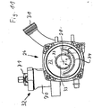
- the mechanical connection of the components 24, 25 and 26 takes place on the one hand via the channel connections (see Fig. 3 ) (34, 64) and on the other via corresponding, not described in detail here connecting webs, which are secured by means of threaded bolts.
- the channel connections are plug-in connections under inclusion of an O-ring, which performs the sealing function of the compound as well as a transversely inserted to the insertion direction U-shaped bracket, which takes over the mechanical lock.
- connections or connecting pieces are partly plug-in connections, threaded connections or flange-like Neck formed.
- the respective designs are only to be understood as examples and can be adapted, exchanged or modified according to the requirements.
- the unit described above is extremely compact and is from the lateral dimensions approximately in alignment with the plate heat exchanger arranged rearwardly so that the entire unit between vertical struts of the chassis of the compact heating system is einliederbar, whereby the overall depth of the entire system can be reduced , Furthermore, all major units and fittings are accessible from the front or from the above the unit formed space so that they can be replaced and serviced without disassembly of the unit.
- the design of the pump housing component 24, in particular in the rear part results in detail from the Figures 10 and 11 as well as in the installed state from the Figures 3 and 5 , As these representations illustrate, the actual pump housing is stepped back and extends below the plate heat exchanger 5, where from the right (seen from the front) of the suction channel 34 and from the left of the transverse channel 64 connects to the bypass line 13.
- This the heat exchanger 5 on its underside superior part 75 of the pump housing is upstream of the actual suction chamber and forms part of a Beerabscheide observed, the actual separator 32 adjoins the top and consists of a Heilabscheidehunt 70 and this up to the final vent valve 71.
- the suction chamber of the pump which is separated from the pressure chamber by a plate 72, opens into the suction mouth 33, which in its upper region is surrounded by an upper guide body 73 extending from the plate 72 backwards to the housing wall, approximately over 190 °. Downwardly at a distance, the suction mouth is surrounded by a lower guide body 74 which engages over the lower ends of the upper guide body 73 laterally and at a distance and also protrudes up to the rear housing wall of the pump housing component 24, specifically Fig. 10
- the arrangement of the guide body 73 and 74 is such that the flow entering from the suction channel 34 to the in. Under the plate heat exchanger 5 lying below the plate heat exchanger 5 Fig.
- bypass channel 64 also opens in the bottom of the suction chamber, under the lower guide body 74th
Landscapes
- Engineering & Computer Science (AREA)
- Mechanical Engineering (AREA)
- Physics & Mathematics (AREA)
- Thermal Sciences (AREA)
- Chemical & Material Sciences (AREA)
- Combustion & Propulsion (AREA)
- General Engineering & Computer Science (AREA)
- Water Supply & Treatment (AREA)
- Steam Or Hot-Water Central Heating Systems (AREA)
- Heat-Exchange Devices With Radiators And Conduit Assemblies (AREA)
- Resistance Heating (AREA)
- Basic Packing Technique (AREA)
- Yarns And Mechanical Finishing Of Yarns Or Ropes (AREA)
Priority Applications (5)
| Application Number | Priority Date | Filing Date | Title |
|---|---|---|---|
| AT03025084T ATE397737T1 (de) | 2003-11-03 | 2003-11-03 | Baueinheit für eine kompaktheizungsanlage |
| DE50309957T DE50309957D1 (de) | 2003-11-03 | 2003-11-03 | Baueinheit für eine Kompaktheizungsanlage |
| EP03025084A EP1528330B1 (de) | 2003-11-03 | 2003-11-03 | Baueinheit für eine Kompaktheizungsanlage |
| CNB2004100883561A CN100526749C (zh) | 2003-11-03 | 2004-11-03 | 用于紧凑型供暖设备的组件单元 |
| PL371000A PL211735B1 (pl) | 2003-11-03 | 2004-11-03 | Jednostka konstrukcyjna zblokowanej instalacji grzewczej |
Applications Claiming Priority (1)
| Application Number | Priority Date | Filing Date | Title |
|---|---|---|---|
| EP03025084A EP1528330B1 (de) | 2003-11-03 | 2003-11-03 | Baueinheit für eine Kompaktheizungsanlage |
Publications (2)
| Publication Number | Publication Date |
|---|---|
| EP1528330A1 EP1528330A1 (de) | 2005-05-04 |
| EP1528330B1 true EP1528330B1 (de) | 2008-06-04 |
Family
ID=34400512
Family Applications (1)
| Application Number | Title | Priority Date | Filing Date |
|---|---|---|---|
| EP03025084A Expired - Lifetime EP1528330B1 (de) | 2003-11-03 | 2003-11-03 | Baueinheit für eine Kompaktheizungsanlage |
Country Status (5)
| Country | Link |
|---|---|
| EP (1) | EP1528330B1 (pl) |
| CN (1) | CN100526749C (pl) |
| AT (1) | ATE397737T1 (pl) |
| DE (1) | DE50309957D1 (pl) |
| PL (1) | PL211735B1 (pl) |
Cited By (3)
| Publication number | Priority date | Publication date | Assignee | Title |
|---|---|---|---|---|
| EP2093517A1 (de) | 2008-02-22 | 2009-08-26 | Grundfos Management A/S | Baueinheit für eine Kompaktheizungsanlage |
| DE102009048585A1 (de) | 2009-10-07 | 2011-04-14 | Stiebel Eltron Gmbh & Co. Kg | Hydraulikmodul für ein Haustechnikgerät und Wärmepumpe mit einem Hydraulikmodul |
| DE102018006784A1 (de) * | 2018-08-28 | 2020-03-05 | EnTEC P & L GmbH | Pumpengruppe für ein Heizungssystem |
Families Citing this family (19)
| Publication number | Priority date | Publication date | Assignee | Title |
|---|---|---|---|---|
| ITMI20060751A1 (it) * | 2006-04-14 | 2007-10-15 | Fugas S P A | Gruppo idraulico di ritorno per caldaie murali |
| ITMI20060773A1 (it) * | 2006-04-19 | 2007-10-20 | Fugas S P A | Circuito idraulico per il riscaldamento e la produzione di acqua calda sanitaria ottenuti da una sorgente si acqua calda centralizzata |
| EP1884720B1 (de) * | 2006-07-28 | 2016-01-13 | Grundfos Management A/S | Baueinheit für eine Kompaktheizungsanlage |
| EP1884717B1 (de) * | 2006-07-28 | 2016-01-13 | Grundfos Management A/S | Heizungsanlage |
| ATE405801T1 (de) * | 2006-07-28 | 2008-09-15 | Grundfos Management As | Baueinheit |
| ITMI20070370A1 (it) * | 2007-02-27 | 2008-08-28 | Fugas S P A | Gruppo idraulico con doppio scambiatore secondario per inmpianti con caldaie a gas |
| EP2093515B1 (de) | 2008-02-22 | 2011-08-17 | Grundfos Management A/S | Teilbaueinheit für eine Kompaktheizungsanlage |
| DE502008003346D1 (de) | 2008-02-22 | 2011-06-09 | Grundfos Management As | Baueinheit für eine Kompaktheizungsanlage |
| ITMI20090527A1 (it) * | 2009-04-01 | 2010-10-02 | Gruppo Imar S P A | Modulo di collegamento idraulico alle utenze termiche di un impianto di climatizzazione bivalente ed impianto di climatizzazione includente tale modulo |
| EP2397777B1 (de) | 2010-06-19 | 2016-08-03 | Grundfos Management A/S | Gehäuseeinheit für eine Heizungsanlage |
| EP2413045B1 (de) * | 2010-07-30 | 2014-02-26 | Grundfos Management A/S | Wärmetauschereinheit |
| JP5777433B2 (ja) * | 2010-08-04 | 2015-09-09 | 株式会社東芝 | 燃料電池発電システムおよびその製造方法 |
| EP2629019B1 (de) * | 2012-02-17 | 2016-04-13 | Grundfos Holding A/S | Gehäuseeinheit für ein Heizgerät |
| EP3012552B1 (de) * | 2014-10-21 | 2018-01-31 | Grundfos Holding A/S | Baueinheit für eine Kompaktheizungsanlage |
| EP3012553B1 (de) * | 2014-10-21 | 2018-01-17 | Grundfos Holding A/S | Baueinheit für eine Heizungsanlage |
| DE202015105452U1 (de) | 2015-10-15 | 2016-01-29 | Viessmann Werke Gmbh & Co Kg | Heizgerät |
| EP3156660B1 (de) | 2015-10-15 | 2022-04-13 | Grundfos Holding A/S | Hauswasserwerk mit kreiselpumpe und membrandruckbehälter |
| ITUB20160469A1 (it) * | 2016-01-22 | 2017-07-22 | Ivar Spa | Dispositivo di regolazione per impianti termici |
| TR202017937A2 (tr) * | 2020-11-10 | 2021-09-21 | Daikin Europe Nv | Hi̇droblok si̇stemleri̇ i̇çi̇n bi̇r güvenli̇k yapilandirmasi |
Family Cites Families (3)
| Publication number | Priority date | Publication date | Assignee | Title |
|---|---|---|---|---|
| IT1298069B1 (it) * | 1997-10-20 | 1999-12-20 | Valter Falavegna | Gruppo valvolare a distribuzione idraulica integrale particolarmente per caldaie murali da riscaldamento e produzione di acqua calda |
| DE19751515C2 (de) * | 1997-11-21 | 1999-12-02 | Grundfos A S Bjerringbro | Baueinheit für eine Kompaktheizungsanlage |
| DE10007873C1 (de) * | 2000-02-21 | 2001-06-28 | Grundfos As | Baueinheit für eine Kompaktheizungsanlage |
-
2003
- 2003-11-03 DE DE50309957T patent/DE50309957D1/de not_active Expired - Lifetime
- 2003-11-03 AT AT03025084T patent/ATE397737T1/de not_active IP Right Cessation
- 2003-11-03 EP EP03025084A patent/EP1528330B1/de not_active Expired - Lifetime
-
2004
- 2004-11-03 CN CNB2004100883561A patent/CN100526749C/zh not_active Expired - Fee Related
- 2004-11-03 PL PL371000A patent/PL211735B1/pl unknown
Cited By (4)
| Publication number | Priority date | Publication date | Assignee | Title |
|---|---|---|---|---|
| EP2093517A1 (de) | 2008-02-22 | 2009-08-26 | Grundfos Management A/S | Baueinheit für eine Kompaktheizungsanlage |
| DE102009048585A1 (de) | 2009-10-07 | 2011-04-14 | Stiebel Eltron Gmbh & Co. Kg | Hydraulikmodul für ein Haustechnikgerät und Wärmepumpe mit einem Hydraulikmodul |
| EP2312224A2 (de) | 2009-10-07 | 2011-04-20 | STIEBEL ELTRON GmbH & Co. KG | Hydraulikmodul für ein Haustechnikgerät und Wärmepumpe mit einem Hydraulikmodul |
| DE102018006784A1 (de) * | 2018-08-28 | 2020-03-05 | EnTEC P & L GmbH | Pumpengruppe für ein Heizungssystem |
Also Published As
| Publication number | Publication date |
|---|---|
| PL211735B1 (pl) | 2012-06-29 |
| PL371000A1 (pl) | 2005-05-16 |
| EP1528330A1 (de) | 2005-05-04 |
| ATE397737T1 (de) | 2008-06-15 |
| CN1619234A (zh) | 2005-05-25 |
| CN100526749C (zh) | 2009-08-12 |
| DE50309957D1 (de) | 2008-07-17 |
Similar Documents
| Publication | Publication Date | Title |
|---|---|---|
| EP1528330B1 (de) | Baueinheit für eine Kompaktheizungsanlage | |
| EP1528329B1 (de) | Baueinheit für eine Kompaktheizungsanlage | |
| EP2397777B1 (de) | Gehäuseeinheit für eine Heizungsanlage | |
| EP2312224B1 (de) | Wärmepumpe mit einem Hydraulikmodul | |
| DE19637817A1 (de) | Einrichtung und Verfahren zum Kühlen und Vorwärmen | |
| EP1418387B1 (de) | Kompaktheizungsanlage mit zwei Heizkreisen | |
| EP0874201B2 (de) | Baueinheit für eine Kompaktheizungsanlage | |
| EP3504433A1 (de) | Motor-pumpenvorrichtung | |
| EP1130342B2 (de) | Baueinheit für eine Kompaktheizungsanlage | |
| DE202015001818U1 (de) | Warmwasserspeicher mit zwei Behältern | |
| EP2093517B1 (de) | Baueinheit für eine Kompaktheizungsanlage | |
| EP1884720B1 (de) | Baueinheit für eine Kompaktheizungsanlage | |
| EP3012553B1 (de) | Baueinheit für eine Heizungsanlage | |
| DE19912284A1 (de) | Kompaktheizungsanlage | |
| EP1884723B1 (de) | Baueinheit | |
| EP1884717B1 (de) | Heizungsanlage | |
| DE202008015206U1 (de) | Nachrüstbausatz für einen Heizkessel zur Gebäudeheizung | |
| EP2629019B1 (de) | Gehäuseeinheit für ein Heizgerät | |
| EP1217310B1 (de) | Kompaktaggregat | |
| DE10050128A1 (de) | Filtervorrichtung | |
| EP1528328B1 (de) | Baueinheit für eine Kompaktheizungsanlage | |
| EP2093516B1 (de) | Baueinheit für eine Kompaktheizungsanlage | |
| EP1528371A1 (de) | Baueinheit für eine Kompaktheizungsanlage | |
| EP1014005A2 (de) | Einrichtung für eine Heizungsanlage, mit einer hydraulischen Weiche und mit einem Heizkreisverteiler | |
| DE202008003241U1 (de) | Vorrichtung geeignet für ein Wärmemanagementsystem eines Raums |
Legal Events
| Date | Code | Title | Description |
|---|---|---|---|
| PUAI | Public reference made under article 153(3) epc to a published international application that has entered the european phase |
Free format text: ORIGINAL CODE: 0009012 |
|
| AK | Designated contracting states |
Kind code of ref document: A1 Designated state(s): AT BE BG CH CY CZ DE DK EE ES FI FR GB GR HU IE IT LI LU MC NL PT RO SE SI SK TR |
|
| AX | Request for extension of the european patent |
Extension state: AL LT LV MK |
|
| 17P | Request for examination filed |
Effective date: 20050405 |
|
| AKX | Designation fees paid |
Designated state(s): AT BE BG CH CY CZ DE DK EE ES FI FR GB GR HU IE IT LI LU MC NL PT RO SE SI SK TR |
|
| GRAP | Despatch of communication of intention to grant a patent |
Free format text: ORIGINAL CODE: EPIDOSNIGR1 |
|
| GRAS | Grant fee paid |
Free format text: ORIGINAL CODE: EPIDOSNIGR3 |
|
| GRAA | (expected) grant |
Free format text: ORIGINAL CODE: 0009210 |
|
| AK | Designated contracting states |
Kind code of ref document: B1 Designated state(s): AT BE BG CH CY CZ DE DK EE ES FI FR GB GR HU IE IT LI LU MC NL PT RO SE SI SK TR |
|
| REG | Reference to a national code |
Ref country code: GB Ref legal event code: FG4D Free format text: NOT ENGLISH |
|
| REG | Reference to a national code |
Ref country code: CH Ref legal event code: EP |
|
| REF | Corresponds to: |
Ref document number: 50309957 Country of ref document: DE Date of ref document: 20080717 Kind code of ref document: P |
|
| REG | Reference to a national code |
Ref country code: IE Ref legal event code: FG4D Free format text: LANGUAGE OF EP DOCUMENT: GERMAN |
|
| PG25 | Lapsed in a contracting state [announced via postgrant information from national office to epo] |
Ref country code: FI Free format text: LAPSE BECAUSE OF FAILURE TO SUBMIT A TRANSLATION OF THE DESCRIPTION OR TO PAY THE FEE WITHIN THE PRESCRIBED TIME-LIMIT Effective date: 20080604 Ref country code: SI Free format text: LAPSE BECAUSE OF FAILURE TO SUBMIT A TRANSLATION OF THE DESCRIPTION OR TO PAY THE FEE WITHIN THE PRESCRIBED TIME-LIMIT Effective date: 20080604 Ref country code: ES Free format text: LAPSE BECAUSE OF FAILURE TO SUBMIT A TRANSLATION OF THE DESCRIPTION OR TO PAY THE FEE WITHIN THE PRESCRIBED TIME-LIMIT Effective date: 20080915 |
|
| REG | Reference to a national code |
Ref country code: IE Ref legal event code: FD4D |
|
| REG | Reference to a national code |
Ref country code: HU Ref legal event code: AG4A Ref document number: E004008 Country of ref document: HU |
|
| PG25 | Lapsed in a contracting state [announced via postgrant information from national office to epo] |
Ref country code: SE Free format text: LAPSE BECAUSE OF FAILURE TO SUBMIT A TRANSLATION OF THE DESCRIPTION OR TO PAY THE FEE WITHIN THE PRESCRIBED TIME-LIMIT Effective date: 20080904 Ref country code: PT Free format text: LAPSE BECAUSE OF FAILURE TO SUBMIT A TRANSLATION OF THE DESCRIPTION OR TO PAY THE FEE WITHIN THE PRESCRIBED TIME-LIMIT Effective date: 20081104 Ref country code: IE Free format text: LAPSE BECAUSE OF FAILURE TO SUBMIT A TRANSLATION OF THE DESCRIPTION OR TO PAY THE FEE WITHIN THE PRESCRIBED TIME-LIMIT Effective date: 20080604 |
|
| PG25 | Lapsed in a contracting state [announced via postgrant information from national office to epo] |
Ref country code: SK Free format text: LAPSE BECAUSE OF FAILURE TO SUBMIT A TRANSLATION OF THE DESCRIPTION OR TO PAY THE FEE WITHIN THE PRESCRIBED TIME-LIMIT Effective date: 20080604 Ref country code: RO Free format text: LAPSE BECAUSE OF FAILURE TO SUBMIT A TRANSLATION OF THE DESCRIPTION OR TO PAY THE FEE WITHIN THE PRESCRIBED TIME-LIMIT Effective date: 20080604 |
|
| PLBE | No opposition filed within time limit |
Free format text: ORIGINAL CODE: 0009261 |
|
| STAA | Information on the status of an ep patent application or granted ep patent |
Free format text: STATUS: NO OPPOSITION FILED WITHIN TIME LIMIT |
|
| PG25 | Lapsed in a contracting state [announced via postgrant information from national office to epo] |
Ref country code: BG Free format text: LAPSE BECAUSE OF FAILURE TO SUBMIT A TRANSLATION OF THE DESCRIPTION OR TO PAY THE FEE WITHIN THE PRESCRIBED TIME-LIMIT Effective date: 20080904 Ref country code: EE Free format text: LAPSE BECAUSE OF FAILURE TO SUBMIT A TRANSLATION OF THE DESCRIPTION OR TO PAY THE FEE WITHIN THE PRESCRIBED TIME-LIMIT Effective date: 20080604 Ref country code: DK Free format text: LAPSE BECAUSE OF FAILURE TO SUBMIT A TRANSLATION OF THE DESCRIPTION OR TO PAY THE FEE WITHIN THE PRESCRIBED TIME-LIMIT Effective date: 20080604 |
|
| 26N | No opposition filed |
Effective date: 20090305 |
|
| BERE | Be: lapsed |
Owner name: GRUNDFOS A/S Effective date: 20081130 |
|
| PG25 | Lapsed in a contracting state [announced via postgrant information from national office to epo] |
Ref country code: MC Free format text: LAPSE BECAUSE OF NON-PAYMENT OF DUE FEES Effective date: 20081130 |
|
| REG | Reference to a national code |
Ref country code: CH Ref legal event code: PL |
|
| PG25 | Lapsed in a contracting state [announced via postgrant information from national office to epo] |
Ref country code: BE Free format text: LAPSE BECAUSE OF NON-PAYMENT OF DUE FEES Effective date: 20081130 |
|
| PG25 | Lapsed in a contracting state [announced via postgrant information from national office to epo] |
Ref country code: CH Free format text: LAPSE BECAUSE OF NON-PAYMENT OF DUE FEES Effective date: 20081130 Ref country code: LI Free format text: LAPSE BECAUSE OF NON-PAYMENT OF DUE FEES Effective date: 20081130 |
|
| PG25 | Lapsed in a contracting state [announced via postgrant information from national office to epo] |
Ref country code: AT Free format text: LAPSE BECAUSE OF NON-PAYMENT OF DUE FEES Effective date: 20081103 |
|
| PG25 | Lapsed in a contracting state [announced via postgrant information from national office to epo] |
Ref country code: LU Free format text: LAPSE BECAUSE OF NON-PAYMENT OF DUE FEES Effective date: 20081103 Ref country code: CY Free format text: LAPSE BECAUSE OF FAILURE TO SUBMIT A TRANSLATION OF THE DESCRIPTION OR TO PAY THE FEE WITHIN THE PRESCRIBED TIME-LIMIT Effective date: 20080604 |
|
| PG25 | Lapsed in a contracting state [announced via postgrant information from national office to epo] |
Ref country code: TR Free format text: LAPSE BECAUSE OF FAILURE TO SUBMIT A TRANSLATION OF THE DESCRIPTION OR TO PAY THE FEE WITHIN THE PRESCRIBED TIME-LIMIT Effective date: 20080604 |
|
| PG25 | Lapsed in a contracting state [announced via postgrant information from national office to epo] |
Ref country code: GR Free format text: LAPSE BECAUSE OF FAILURE TO SUBMIT A TRANSLATION OF THE DESCRIPTION OR TO PAY THE FEE WITHIN THE PRESCRIBED TIME-LIMIT Effective date: 20080905 |
|
| REG | Reference to a national code |
Ref country code: FR Ref legal event code: PLFP Year of fee payment: 14 |
|
| REG | Reference to a national code |
Ref country code: FR Ref legal event code: PLFP Year of fee payment: 15 |
|
| PGFP | Annual fee paid to national office [announced via postgrant information from national office to epo] |
Ref country code: CZ Payment date: 20211022 Year of fee payment: 19 Ref country code: DE Payment date: 20211123 Year of fee payment: 19 Ref country code: NL Payment date: 20211119 Year of fee payment: 19 Ref country code: GB Payment date: 20211123 Year of fee payment: 19 Ref country code: FR Payment date: 20211119 Year of fee payment: 19 |
|
| PGFP | Annual fee paid to national office [announced via postgrant information from national office to epo] |
Ref country code: IT Payment date: 20211130 Year of fee payment: 19 Ref country code: HU Payment date: 20211030 Year of fee payment: 19 |
|
| REG | Reference to a national code |
Ref country code: DE Ref legal event code: R119 Ref document number: 50309957 Country of ref document: DE |
|
| REG | Reference to a national code |
Ref country code: NL Ref legal event code: MM Effective date: 20221201 |
|
| GBPC | Gb: european patent ceased through non-payment of renewal fee |
Effective date: 20221103 |
|
| PG25 | Lapsed in a contracting state [announced via postgrant information from national office to epo] |
Ref country code: HU Free format text: LAPSE BECAUSE OF NON-PAYMENT OF DUE FEES Effective date: 20221104 Ref country code: CZ Free format text: LAPSE BECAUSE OF NON-PAYMENT OF DUE FEES Effective date: 20221103 |
|
| PG25 | Lapsed in a contracting state [announced via postgrant information from national office to epo] |
Ref country code: NL Free format text: LAPSE BECAUSE OF NON-PAYMENT OF DUE FEES Effective date: 20221201 |
|
| PG25 | Lapsed in a contracting state [announced via postgrant information from national office to epo] |
Ref country code: IT Free format text: LAPSE BECAUSE OF NON-PAYMENT OF DUE FEES Effective date: 20221103 Ref country code: GB Free format text: LAPSE BECAUSE OF NON-PAYMENT OF DUE FEES Effective date: 20221103 Ref country code: DE Free format text: LAPSE BECAUSE OF NON-PAYMENT OF DUE FEES Effective date: 20230601 |
|
| PG25 | Lapsed in a contracting state [announced via postgrant information from national office to epo] |
Ref country code: FR Free format text: LAPSE BECAUSE OF NON-PAYMENT OF DUE FEES Effective date: 20221130 |