EP1528329B1 - Baueinheit für eine Kompaktheizungsanlage - Google Patents
Baueinheit für eine Kompaktheizungsanlage Download PDFInfo
- Publication number
- EP1528329B1 EP1528329B1 EP03025083A EP03025083A EP1528329B1 EP 1528329 B1 EP1528329 B1 EP 1528329B1 EP 03025083 A EP03025083 A EP 03025083A EP 03025083 A EP03025083 A EP 03025083A EP 1528329 B1 EP1528329 B1 EP 1528329B1
- Authority
- EP
- European Patent Office
- Prior art keywords
- pump housing
- heat exchanger
- plate heat
- construction unit
- unit according
- Prior art date
- Legal status (The legal status is an assumption and is not a legal conclusion. Google has not performed a legal analysis and makes no representation as to the accuracy of the status listed.)
- Expired - Lifetime
Links
Images


Classifications
-
- F—MECHANICAL ENGINEERING; LIGHTING; HEATING; WEAPONS; BLASTING
- F24—HEATING; RANGES; VENTILATING
- F24H—FLUID HEATERS, e.g. WATER OR AIR HEATERS, HAVING HEAT-GENERATING MEANS, e.g. HEAT PUMPS, IN GENERAL
- F24H9/00—Details
- F24H9/14—Arrangements for connecting different sections, e.g. in water heaters
-
- F—MECHANICAL ENGINEERING; LIGHTING; HEATING; WEAPONS; BLASTING
- F24—HEATING; RANGES; VENTILATING
- F24D—DOMESTIC- OR SPACE-HEATING SYSTEMS, e.g. CENTRAL HEATING SYSTEMS; DOMESTIC HOT-WATER SUPPLY SYSTEMS; ELEMENTS OR COMPONENTS THEREFOR
- F24D19/00—Details
- F24D19/08—Arrangements for drainage, venting or aerating
- F24D19/082—Arrangements for drainage, venting or aerating for water heating systems
- F24D19/083—Venting arrangements
-
- F—MECHANICAL ENGINEERING; LIGHTING; HEATING; WEAPONS; BLASTING
- F24—HEATING; RANGES; VENTILATING
- F24D—DOMESTIC- OR SPACE-HEATING SYSTEMS, e.g. CENTRAL HEATING SYSTEMS; DOMESTIC HOT-WATER SUPPLY SYSTEMS; ELEMENTS OR COMPONENTS THEREFOR
- F24D3/00—Hot-water central heating systems
- F24D3/08—Hot-water central heating systems in combination with systems for domestic hot-water supply
-
- F—MECHANICAL ENGINEERING; LIGHTING; HEATING; WEAPONS; BLASTING
- F24—HEATING; RANGES; VENTILATING
- F24H—FLUID HEATERS, e.g. WATER OR AIR HEATERS, HAVING HEAT-GENERATING MEANS, e.g. HEAT PUMPS, IN GENERAL
- F24H1/00—Water heaters, e.g. boilers, continuous-flow heaters or water-storage heaters
- F24H1/48—Water heaters for central heating incorporating heaters for domestic water
- F24H1/52—Water heaters for central heating incorporating heaters for domestic water incorporating heat exchangers for domestic water
-
- F—MECHANICAL ENGINEERING; LIGHTING; HEATING; WEAPONS; BLASTING
- F24—HEATING; RANGES; VENTILATING
- F24H—FLUID HEATERS, e.g. WATER OR AIR HEATERS, HAVING HEAT-GENERATING MEANS, e.g. HEAT PUMPS, IN GENERAL
- F24H9/00—Details
- F24H9/14—Arrangements for connecting different sections, e.g. in water heaters
- F24H9/142—Connecting hydraulic components
Definitions
- the invention relates to a structural unit for a compact heating system according to the features specified in the preamble in claim 1.
- Such units are state of the art and serve to simplify or largely replace the piping within the compact heating system and also to accommodate a variety of fittings, such as valves, sensors and the like.
- a compact design can be achieved on the other hand, the manufacturing and in particular assembly costs of the heating system can be reduced and finally the maintenance and repair can be simplified.
- Such a unit for a compact heating system is known, for a compact heating system with two heating circuits, namely one for heating the heating water for the central heating and another for heating the service water.
- the assembly described therein is already comparatively compact and consists essentially of three injection molded parts, of which the first forms the centrally arranged pump housing, connect to the valve body on both sides, one of which receives an air separation device.
- the back of the unit is provided for connection of a plate heat exchanger, which is intended for heating the service water.
- this unit comparatively much space is required for the arranged next to the pump housing air separator.
- the depth is determined by the unit plus the plate heat exchanger.
- the unfavorable is the out EP 0 911 590 A2 known construction in which the pump unit is set in the installation position temporally ver and arranged in front of the plate heat exchanger.
- This construction increases both in terms of width and in terms of. the building depth considerable space.
- the invention has the object, a generic unit for a compact heating system in such a way that the size, in particular the depth can be further reduced.
- the basic idea of the present invention is to associate at least part of the air separation device with the pump housing or the pump housing component and thereby form the pump housing in such a way that it projects beyond the plate heat exchanger on one side.
- the space above or below the plate heat exchanger can advantageously be used for the pump housing.
- This additionally available installation space again makes it possible, for example in this area of the pump housing, to integrate the air separation device, at least parts of it, in order in this way to be able to build the unit in a more compact and space-saving manner.
- the pump housing is preferably designed such that it extends below the plate heat exchanger so that the free space located there and not used can serve as additional space for the pump housing.
- This additional space is advantageously used in conjunction with the Heilabscheide founded and serves to guide or calm the flow so that in this area the air entrained in the water separated and finally passed through a vent valve to the outside, whereas the liquid flow as far as possible free of air is led to the suction mouth of the pump.
- the pump housing is designed stepped on the suction side, wherein the stepped part is arranged below the plate heat exchanger.
- a nozzle-like extension may be provided, preferably in such a way that the nozzle or nozzles opening there are widened to the suction mouth of the pump, so that here too a flow slowdown and thus separation of entrained gas, in particular air is taken from the liquid stream.
- the flow velocity is slowed specifically for the purpose of air separation
- the air separation in the arranged below the plate heat exchanger graduated part of the pump housing can be supported according to a development of the invention even further characterized in that at least one guide body is provided within the pump housing, in particular in this aforementioned part of the housing.
- two cooperating guide body are provided, namely a lower, which surrounds the lower part of the suction mouth of the pump and an upper which surrounds the upper part of the suction mouth of the pump, which, however, do not abut each other, but end at a distance to each other.
- the lower guide body is preferably long-running, that is, pulled far below the plate heat exchanger, whereas the upper guide body is short and also has a smaller radius, so that its lateral ends terminate within the space surrounding the lower guide body.
- Both guide bodies extend to just in front of the rear housing wall, so that they force the flow and divert by 180 °.
- This guide ensure in a particularly effective way that the still entrained in the liquid flow bubbles are pushed upwards, ie to the venting chamber and do not reach the suction port of the pump.
- the under the plate heat exchanger extending stepped pump housing part is used in an advantageous embodiment of the invention still for connecting a bypass line, which then also be arranged in this area under the plate heat exchanger can and can be formed by drawing cores in the tool for the pump housing.
- the suction-side line opens advantageously, and the bypass and suction-side lines are preferably arranged such that they are each guided transversely to different sides below the plate heat exchanger, so that both line connections can be formed without melting cores in the tool.
- Fig. 1 shown compact heating system is a gas boiler, as it is typically intended for wall mounting as a compact device for heat supply working with radiators space heating and for hot water / hot water production.
- a burner 1 acts on a primary heat exchanger 2, the heated water of a heat exchanger 3, typically in the form of one or more radiators for space heating, is supplied.
- the cooled water flows from the heat exchanger 3 back to the primary heat exchanger 2 and is circulated by means of a arranged on the cold side of the heat exchanger 2, 3 circulation pump 4.
- a plate heat exchanger 5 is provided, in which the coming from the water network cold hot water is heated. Since the heating of the service water has to be done only in the removal case, is appropriate sensors, in particular a flow meter 6 as well as a pressure and temperature sensor 7 is provided, depending on the output signal, a servomotor 8 is driven, which controls a 3/2-way valve 9, for the domestic water heating coming from the primary heat exchanger 2 heat-conducting liquid flow instead of the heat exchanger 3 to the plate heat exchanger 5 to redirect.
- a surge tank 10 is provided and a heat storage 11, which is connected in series between plate heat exchanger 5 and the primary heat exchanger 2, here on the cold side.
- Fig. 1 with 3 symbolized heat exchanger is, as usual today in hot water heating systems, provided with a thermostatic valve 12, which controls the circuit in terms of flow resistance and then, if no heat demand is given locks.
- a bypass line 13 is provided within the compact heating system with a valve 14, via which the hydraulically effective line cross section of the bypass line 13 is adjustable. Through this bypass line 13, a closed circulation circuit is ensured, even if the thermostatic valve 12 is fully closed.
- a safety valve 15 in the form of a pressure relief valve suction side of the pump 4 are provided and two shut-off valves 16 and 17, which are connected via a line 18 to each other.
- the heating system has a total of four line connections in the form of plug connections, namely a connection 19 for the heating flow as a port 20 for the heating return. Furthermore, there is a connection 21 provided for the domestic water inlet and a connection 22 for coming out of the plant hot water.
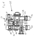
- FIG. 1 framed by broken lines part of the compact heating system is formed by a structural unit 23, the structure of the basis of FIGS. 2 to 9 is shown in detail.
- the assembly 23 is essentially composed of three injection-molded parts, namely a central, the pump housing-containing pump housing component 24, to the left in installation position seen from the front left a dashboard housing 25 and the right side a fitting housing 26.
- the components 24, 25 and 26 are fabricated as plastic injection molded components and designed to operate without the use of fused cores, i. H. can be manufactured with comparatively inexpensive tools that work with drawing cores.
- These components 24 to 26 are incorporated into each other in the transverse direction 27 to the impeller axis 28 of the pump and are positively secured by the rear-connected plate heat exchanger 5 in this position.
- the pump housing component 24 has the actual pump housing and a forwardly open insertion space 29, which is provided for receiving the pump impeller and for flanging the forward adjoining motor 30.
- the pump housing has an obliquely right above outgoing discharge nozzle 31, the free end is formed as a threaded connection and is provided for connection of the primary heat exchanger 2 leading line.
- an air separator 32 On the suction side connected to the pump housing or integrated into the pump housing component 24 is an air separator 32, in which a conventional Lucasabscheideventil is incorporated.
- the rearwardly directed suction mouth 33 of the pump is conductively connected to the valve housing 26 via a suction channel 34 extending in the transverse direction 27 into which it opens.
- the suction channel 34 continues in the fitting housing 26 continues to the right and opens into a rearwardly extending from the rear channel 35, which merges into a substantially cylindrically shaped, with its cylinder axis parallel to the impeller axis 28 and forward open insertion space 36, which serves as a central Anschussbasis for other connections or lines as well as for receiving fittings.
- a partition wall 39 is pressed into the insertion space 36 from the front.
- This partition wall 39 is formed by a simple sheet metal or a plastic part, since it does not depend on a complete seal to the insertion space 36 out.
- the terminals 37 and 38 are closed by blind caps, so they are out of order.
- the insertion space 36 opens from below a line 40, at the end of the connection 20 is arranged for the heating return.
- the bottom of the insertion space 36 is broken not only to the channel 35, but also in the upper left area (see Fig. 7 ), where a rear channel opens, which runs in alignment with a lower connecting piece 41, which is provided for connection of the plate heat exchanger 5.
- the connecting piece 41 is formed as a pair of connecting pieces together with the overlying connecting piece 42.
- the connecting piece 41 connects the Schuzierniklauf the heat exchanger 5 with the suction side of the pump 4.
- the upper connecting piece 42 connects the hot water leading service water connection of the heat exchanger 5 with a vertically downwardly leading channel 43, which opens into the connection 22 for hot service water.
- connection 66 is provided for the expansion tank 10 upwards.
- the insertion space 36 opens an obliquely coming from above and front receiving opening 44 which is provided at the end with a part of a bayonet fitting and in which a combined pressure and temperature sensor 45 is incorporated as a plug-in part, which is equipped with the other part of the bayonet closure ,
- the insertion space 36 itself serves to receive a Schmutzabscheiders 46, which is inserted in the manner of a sieve in this and arranged so that the coming of the terminal 20, ie from the heating return water must penetrate this before it reaches the suction channel 34 of the pump.
- the dirt separator 46 is held in a form-fitting manner and can be pulled out to the front for cleaning purposes.
- the insertion space 36 is provided towards the front with a bayonet closure, so that a corresponding lid can be placed without tools for the conclusion of the insertion space 36 and optionally removed again. It is understood that appropriate O-rings are provided as seals at the required locations.
- a safety valve 15 is incorporated in the lid 47 in the form of a pressure relief valve.
- the lid 47 forms part of the safety valve 15.
- each transverse channels are connected, which are closed by means of the shut-off valves 16 and 17. These channels are connected to each other via a line 18 which is formed as a separate component.
- the shut-off valve 16 can serve both to fill the system via the line 18 and the open valve 17 as well as for emptying the system after removal of the line 18 due to the horizontal nozzle.
- the conduit 18 is mounted so that it can be detached manually without tools, so that it can be removed or inserted as needed.
- This insertion space 48 serves to receive the 3/2-way valve 9, which is designed in the form of a slide-in fitting, which can be inserted from the front into the insertion space 48 and sealingly locked by means of a bayonet connection.
- the insertion space 48 final bayonet connection is identical to that for the insertion space 29 so that same end cover can be used.
- the insertion fitting 49 has, as best in Fig. 6 can be seen, two sealing seats, which are each closed by a sealing body.
- the sealing bodies are seated on a rod 50 arranged parallel to the rotor axis 28 and are aligned and arranged such that they always close in the direction of flow, whereby when moving the rod 50 in one direction the sealing body moves toward its sealing seat and the other is lifted off the latter or in the opposite direction in the reverse manner.
- the rod 50 is actuated by a lever 51, which is arranged pivotably in a mounting fitting 52, which is incorporated in an upwardly open insertion space 53, which has an opening to the insertion space 48.
- the lever 51 can engage with one end on the rod carrying the sealing body 50 and with its other end to a spindle 54 which is extended by a motor 8 depending on the rotational position more or less.
- the installation fitting 52 comprises the lever 51, the spindle 54 and the motor 8 and is inserted from above into the insertion space 53 with incorporation of an elastic and sealing cuff 56. This cuff seals the passage of the lever 51 without hindering its mobility.
- the installation fitting 52 may additionally be sealed by O-rings relative to the insertion space 53.
- lateral connections 58 on the left side or the connection formed by the pressure port 31 on the right side are arranged particularly advantageously, since the in installation insert from above lines to or from the primary heat exchanger 2 are easy to connect, since they spring in the transverse direction 27 over its entire length and therefore well manipulable, d. H. away from the connection or to the connection are movable.
- the insertion space 48 has on the bottom side an opening to a substantially coaxially extending back channel, in a connection piece 59 for the plate heat exchanger. 5 empties.
- This lower connecting piece 59 belongs to a pair whose upper connecting piece 60 is connected via a transverse channel 61 with a vertically downwardly extending channel 62, which opens into the port 21 for the service water inlet.
- the line connection 58 is conductively connected either to the lower connection piece 59 for the plate heat exchanger 5 or to the connection 19 for the heating flow.
- the insertion space 48 forms a connection base for almost all on this side of the pump leading channels.
- a channel 63 extending parallel to the rotor axis 28 adjoins the channel 63 which extends perpendicularly downwards to the connection 19 and together with the channel 64 running transversely thereto, opening into the channel region 63 and extending in the direction 27, the bypass line 13 forms.
- the transverse channel 64 opens in the lower rear region of the pump housing, ie in the suction chamber thereof, as in FIG Fig. 5 is clearly visible.
- a spring-loaded valve 14 is inserted from behind, through which the effective cross section of the bypass line 13 is pressure-dependent.
- On the vertical, leading to the port 21 channel 62 is a receptacle for a further pressure-temperature sensor 45 is provided to the front. Recording and sensor are formed in the same manner as that of the right fitting housing 26.
- This pressure / temperature sensor 45 which is inserted from the front, projects into the vertical and rear-side channel 62, which leads to the connection 21 for the service water inlet.
- the pressure sensor in conjunction with an obstruction formed in the channel 62 forms part of the flow meter 6 described in the introduction, in conjunction with a corresponding evaluation electronics, which is arranged in the terminal box 65.
- the terminal box 65 is provided, which is arranged on the housing of the motor 30 and thus associated with the pump housing component 24.
- the mechanical connection of the components 24, 25 and 26 takes place on the one hand via the channel connections (see Fig. 3 ) (34, 64) and on the other via corresponding, not described in detail here connecting webs, which are secured by means of threaded bolts.
- the channel connections are plug-in connections under inclusion of an O-ring, which performs the sealing function of the compound as well as a transversely inserted to the insertion direction U-shaped bracket, which takes over the mechanical lock.
- connections or connecting pieces described above are partially designed as plug-in connections, threaded connections or flange-like connection pieces.
- the respective designs are only to be understood as examples and can be adapted, exchanged or modified according to the requirements.
- the unit described above is extremely compact and is from the lateral dimensions approximately in alignment with the plate heat exchanger arranged rearwardly so that the entire unit between vertical struts of the chassis of the compact heating system is einliederbar, whereby the overall depth of the entire system can be reduced , Furthermore, all major units and fittings are accessible from the front or from the above the unit formed space so that they can be replaced and serviced without disassembly of the unit.
- the design of the pump housing component 24, in particular in the rear part results in detail from the Figures 10 and 11 as well as in the installed state from the Figures 3 and 5 ,
- the actual pump housing is stepped back and extends below the plate heat exchanger 5, where from the right (seen from the front) of the suction channel 34 and from the left of the transverse channel 64 connects to the bypass line 13.
- This the heat exchanger 5 on its underside superior part 75 of the pump housing is upstream of the actual suction chamber and forms part of an air separation, the actual separator 32 connects near the top and consists of a Lucasabscheidehunt 70 and this up closing vent valve 71.
- the suction chamber of the pump which is separated from the pressure chamber by a plate 72, opens into the suction mouth 33, which in its upper region is surrounded by an upper guide body 73 extending from the plate 72 backwards to the housing wall, approximately over 190 °. Downwardly at a distance, the suction mouth is surrounded by a lower guide body 74 which engages over the lower ends of the upper guide body 73 laterally and at a distance and also protrudes up to the rear housing wall of the pump housing component 24, specifically Fig. 10
- the arrangement of the guide body 73 and 74 is such that the flow entering from the suction channel 34 to the in. Under the plate heat exchanger 5 lying below the plate heat exchanger 5 Fig.
- bypass channel 64 also opens in the bottom of the suction chamber, under the lower guide body 74th
Landscapes
- Engineering & Computer Science (AREA)
- Mechanical Engineering (AREA)
- Physics & Mathematics (AREA)
- Thermal Sciences (AREA)
- Chemical & Material Sciences (AREA)
- Combustion & Propulsion (AREA)
- General Engineering & Computer Science (AREA)
- Water Supply & Treatment (AREA)
- Heat-Exchange Devices With Radiators And Conduit Assemblies (AREA)
- Steam Or Hot-Water Central Heating Systems (AREA)
- Structures Of Non-Positive Displacement Pumps (AREA)
- Basic Packing Technique (AREA)
- Yarns And Mechanical Finishing Of Yarns Or Ropes (AREA)
- Resistance Heating (AREA)
Description
- Die Erfindung betrifft eine Baueinheit für eine Kompaktheizungsanlage gemäß dem im Oberbegriff in Anspruchs 1 angegebenen Merkmalen.
- Derartige Baueinheiten zählen zum Stand der Technik und dienen dazu, die Verrohrung innerhalb der Kompaktheizungsanlage zu vereinfachen bzw. großteils zu ersetzen sowie darüber hinaus zur Aufnahme einer Vielzahl von Armaturen, wie beispielsweise Ventile, Sensoren und dergleichen. Hierdurch sollen einerseits eine kompakte Bauweise erzielt werden andererseits die Herstellungs- und insbesondere Montagekosten der Heizungsanlage gesenkt werden und schließlich die Wartung und Reparatur vereinfacht werden.
- Aus
DE 100 07 873 C1 ist eine solche Baueinheit für eine Kompaktheizungsanlage bekannt, und zwar für eine Kompaktheizungsanlage mit zwei Heizkreisen, nämlich einem zur Erwärmung des Heizungswassers für die Zentralheizung und einem anderen zur Erwärmung des Brauchwassers. Die dort beschriebene Baueinheit ist schon vergleichsweise kompakt aufgebaut und besteht im Wesentlichen aus drei Spritzgussteilen, von denen das erste das zentral angeordnete Pumpengehäuse bildet, an das zu beiden Seiten Armaturengehäuse anschließen, von denen eines eine Luftabscheideeinrichtung aufnimmt. Rückseitig ist die Baueinheit zum Anschluss eines Plattenwärmertauschers vorgesehen, welcher zur Erwärmung des Brauchwassers bestimmt ist. Bei dieser Baueinheit wird vergleichsweise viel Bauraum für die neben dem Pumpengehäuse angeordnete Luftabscheideeinrichtung benötigt. Darüber hinaus ist die Bautiefe durch die der Baueinheit zuzüglich der des Plattenwärmertauschers bestimmt. - Insoweit noch ungünstiger ist die aus
EP 0 911 590 A2 bekannte Konstruktion, bei welcher das Pumpenaggregat in Einbaulage zeitlich ver setzt und vor dem Plattenwärmetauscher angeordnet ist. Diese Konstruktion nimmt sowohl hinsichtlich der Breite als auch hinsichtlich. der Bautiefe erheblichen Raum ein. - Vor diesem Hintergrund liegt der Erfindung die Aufgabe zugrunde, eine gattungsgemäße Baueinheit für eine Kompaktheizungsanlage so auszubilden, dass die Baugröße, insbesondere die Tiefe noch weiter reduziert werden kann.
- Diese Aufgabe wird gemäß der Erfindung durch die in Anspruch 1 angegebenen Merkmale gelöst. Vorteilhafte Ausgestaltung der Erfindung sind in den Unteransprüchen sowie der nachfolgenden Beschreibung angegeben.
- Grundgedanke der vorliegenden Erfindung ist es, zumindest einen Teil der Luftabscheideeinrichtung dem Pumpengehäuse bzw. dem Pumpengehäusebauteil zuzuordnen und dabei das Pumpengehäuse so auszubilden, dass es dem Plattenwärmertauscher an einer Seite überragt. Durch diese erfindungsgemäße Anordnung kann der Raum über unter oder neben dem Plattenwärmertauscher in vorteilhafter Weise für das Pumpengehäuse genutzt werden. Dieser zusätzlich zur Verfügung stehende Bauraum ermöglicht es wiederum zum Beispiel in diesem Bereich des Pumpengehäuses die Luftabscheideeinrichtung, zumindest Teile davon zu integrieren um auf diese Weise die Baueinheit noch kompakter und Platz sparender bauen zu können.
- Bevorzugt ist dabei das Pumpengehäuse so ausgebildet, dass es bis unter dem Plattenwärmertauscher reicht, so dass der dort befindliche und nicht genutzte Freiraum als zusätzlicher Raum für das Pumpengehäuse dienen kann. Dieser zusätzliche Raum wird in vorteilhafter Weise im Zusammenhang mit der Luftabscheideeinrichtung eingesetzt und dient dazu, die Strömung so zu führen bzw. zu beruhigen, dass in diesem Bereich die im Wasser mitgeführte Luft abgeschieden und schließlich durch ein Entlüftungsventil ins Freie geführt wird, wohingegen der Flüssigkeitsstrom weitest gehend von Luft befreit zum Saugmund der Pumpe geführt wird.
- Vorzugsweise ist hierzu das Pumpengehäuse saugseitig abgestuft ausgebildet, wobei der abgestufte Teil unter dem Plattenwärmertauscher angeordnet ist. Gemäß einer vereinfachten Ausführungsform der Erfindung kann jedoch statt des abgestuften Pumpengehäuses eine stutzenartige Erstreckung vorgesehen sein, bevorzugt derart, dass der oder die dort einmündenden Stutzen zum Saugmund der Pumpe in aufweitend ausgebildet sind, so dass auch hier eine Strömungsverlangsamung und somit Abscheidung von mitgeführten Gas, insbesondere Luft aus dem Flüssigkeitsstrom erfolgt.
- Gerade dieser Teil des Pumpengehäuses, der unter dem Plattenwärmetauscher angeordnet ist, wird zweckmäßigerweise als Teil der Luftabscheideeinrichtung genutzt, da hier ein vergleichsweise großer Freiraum vorhanden ist, der zur Beruhigung der Strömung und zur Abscheidung der Luft genutzt werden kann und ansonsten ungenutzt ist. Dadurch kann der sonst übliche vergleichsweise große Luftabscheidezylinder, wie er beispielsweise aus dem Stand der Technik nach
DE 100 07 873 C1 am Armaturengehäuse neben der Pumpe bekannt ist, weitgehend entfallen bzw. funktionell teilweise in den unter dem Plattenwärmetauscher befindlichen Freiraum gelegt werden. - Zusätzlich zu diesem Raum, in dem die Strömungsgeschwindigkeit gezielt zum Zwecke der Luftabscheidung verlangsamt wird, ist vorzugsweise am nicht abgestuften Teil des Pumpengehäuses, typischerweise oberhalb des Saugmundes eine an das Pumpengehäuse nach oben anschließende Luftscheidekammer vorgesehen, in welche die aus dem Flüssigkeitsstrom abgeschiedene Luft geleitet wird und in der eine Luftwasserschichtung stattfindet, so dass die in der oben liegenden Schicht befindliche Luft in an sich bekannter Weise mittels eines Entlüftungsventils, das am oberen Ende der Luftabscheidekammer vorgesehen ist, ins Freie geleitet werden kann. Da die Luftabscheidekammer nicht wie beim Stand der Technik zum eigentlichen Abscheidevorgang benötigt wird, sondern hierfür bereits der unterhalb des Plattenwärmetauschers angeordnete Gehäuseteil, in welchem eine Strömungsberuhigung und -umlenkung eintritt, kann diese Luftabscheidekammer vergleichsweise kompakt und Platz sparend ausgebildet sein.
- Die Luftabscheidung in dem unter dem Plattenwärmetauscher angeordneten abgestuften Teil des Pumpengehäuses kann gemäß einer Weiterbildung der Erfindung noch dadurch unterstützt werden, dass mindestens ein Leitkörper innerhalb des Pumpengehäuses vorgesehen wird, und zwar insbesondere in diesem vorgenannten Teil des Gehäuses. Bevorzugt sind zwei zusammenwirkende Leitkörper vorgesehen, und zwar ein unterer, welcher den unteren Teil des Saugmunds der Pumpe umgibt sowie ein oberer der den oberen Teil des Saugmunds der Pumpe umgibt, die jedoch nicht aufeinander stoßen, sondern mit Abstand zueinander enden. Dabei ist der untere Leitkörper vorzugsweise lang auslaufend, also bis weit unter dem Plattenwärmetauscher gezogen, wohingegen der obere Leitkörper kurz ausgebildet ist und auch einen geringeren Radius aufweist, so dass seine seitlichen Ende innerhalb des vom unteren Leitkörpers umgebenden Raum enden. Beide Leitkörper reichen bis unmittelbar vor die rückseitige Gehäusewand, so dass sie die Strömung zwangsführen und um 180° umlenken. Diese Leitkörper sorgen in besonderer effektiver Weise dafür, dass die noch im Flüssigkeitsstrom mitgeführten Blasen nach oben, also zur Entlüftungskammer hin gedrängt werden und nicht zum Saugmund der Pumpe gelangen.
Der sich unter dem Plattenwärmetauscher erstreckende abgestufte Pumpengehäuseteil wird in vorteilhafter Weiterbildung der Erfindung noch zum Anschluss eine Bypassleitung genutzt, welche dann ebenfalls in diesem Bereich unter dem Plattenwärmetauscher angeordnet sein kann und durch Ziehkerne im Werkzeug für das Pumpengehäuse ausgebildet werden kann. In gleicher Weise mündet vorteilhaft auch die saugseitige Leitung, bevorzugt sind die Bypass- und die saugseitige Leitung so angeordnet, dass sie jeweils zu unterschiedlichen Seiten unterhalb des Plattenwärmetauschers quer geführt sind, so dass beide Leitungsanschlüsse ohne Schmelzkerne im Werkzeug gebildet werden können. - Die Erfindung ist nachfolgend anhand eines in der Zeichnung dargestellten Ausführungsbeispiels näher erläutert. Es zeigen:
- Fig. 1
- ein vereinfachtes Schaltbild einer Kompaktheizungsanlage mit einer erfindungsgemäßen Baueinheit,
- Fig. 2
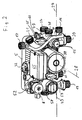
- die komplett bestückte Baueinheit in perspektivischer Ansicht von rechts oben und vorne,
- Fig. 3
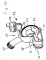
- die Baueinheit nach
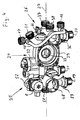
Fig. 2 in perspektivischer Ansicht von rechts unten und hinten, - Fig. 4
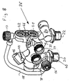
- die Baueinheit in Darstellung nach
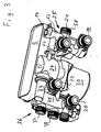
Fig. 2 ohne Pumpenkopf und mit nach vorne offenen, unbestückten Einbauräumen, - Fig. 5
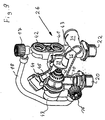
- die Baueinheit nach
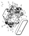
Fig. 2 in perspektivischer Ansicht mit abgenommenen Plattenwärmetauscher von oben links und hinten, - Fig. 6
- einen Schnitt durch das ventilseitige Armaturengehäuse in einer in Einschubrichtung liegenden Ebene,
- Fig. 7
- eine Ansicht der Baueinheit von vorne mit abgenommenen Pumpenkopf und nach vorne offenen und unbestückten Einbauräumen,
- Fig. 8
- in perspektivischer Darstellung von rechts oben und hinten das schmutzabscheiderseitige Armaturengehäuse,
- Fig. 9
- das schmutzabscheiderseitige Armaturengehäuse gemäß
Fig. 8 in teilweiser Schnittdarstellung, - Fig. 10
- den hinter dem Saugmund liegenden Teil des Pumpengehäuses in perspektivischer Teilschnittdarstellung und
- Fig. 11
- einen Schnitt durch das Pumpengehäuse quer zur Laufradachse und in Strömungsrichtung unmittelbar vor dem Saugmund in Ansicht von hinten.
- Die anhand von
Fig. 1 dargestellte Kompaktheizungsanlage ist eine Gastherme, wie sie typischerweise zur Wandmontage als kompaktes Gerät zur Wärmeversorgung einer mit Heizkörpern arbeitenden Raumheizung sowie zur Brauchwasser-/Warmwassererzeugung vorgesehen ist. Ein Brenner 1 beaufschlagt einen Primärwärmetauscher 2, dessen aufgeheiztes Wasser einen Wärmetauscher 3, typischerweise in Form ein oder mehrerer Heizkörper für die Raumheizung, zugeführt wird. Das abgekühlte Wasser fließt aus dem Wärmetauscher 3 wieder zum Primärwärmetauscher 2 und wird mittels einer auf der kalten Seite der Wärmetauscher 2, 3 angeordneten Umwälzpumpe 4 umgewälzt. - Für die Brauchwassererwärmung ist ein Plattenwärmetauscher 5 vorgesehen, in dem das aus dem Wasserleitungsnetz kommende kalte Brauchwasser erwärmt wird. Da die Erwärmung des Brauchwassers nur im Entnahmefall zu erfolgen hat, ist entsprechende Sensorik, insbesondere ein Durchflussmesser 6 so wie ein Druck- und Temperatursensor 7 vorgesehen, in Abhängigkeit deren Ausgangssignal ein Stellmotor 8 angesteuert wird, der ein 3/2-Wegeventil 9 ansteuert, um für die Brauchwassererwärmung den vom Primärwärmetauscher 2 kommenden wärmeführenden Flüssigkeitsstrom statt zum Wärmetauscher 3 zum Plattenwärmetauscher 5 umzusteuern.
- Das Schaubild nach
Fig. 1 erhebt keinen Anspruch auf Vollständigkeit. Innerhalb der Kompaktheizungsanlage ist ein Ausgleichsbehälter 10 vorgesehen sowie ein Wärmespeicher 11, der zwischen Plattenwärmetauscher 5 und dem Primärwärmetauscher 2, hier auf der kalten Seite, in Reihe geschaltet ist. - Der in
Fig. 1 mit 3 symbolisierte Wärmetauscher (Heizkörper) ist, wie heute bei Warmwasserheizungsanlagen üblich, mit einem Thermostatventil 12 versehen, das den Kreislauf hinsichtlich des Durchflusswiderstandes steuert und dann, wenn kein Wärmebedarf gegeben ist, sperrt. Für letzteren Fall ist innerhalb der Kompaktheizungsanlage eine Bypassleitung 13 vorgesehen mit einem Ventil 14, über das der hydraulisch wirksame Leitungsquerschnitt der Bypassleitung 13 einstellbar ist. Durch diese Bypassleitung 13 ist ein geschlossener Umwälzkreislauf sichergestellt, selbst wenn das Thermostatventil 12 vollständig geschlossen ist. - Weiterhin sind ein Sicherheitsventil 15 in Form eines Überdruckventils saugseitig der Pumpe 4 vorgesehen sowie zwei Absperrventile 16 und 17, die über eine Leitung 18 miteinander verbunden sind.
- Neben den elektrischen und Gasleitungsanschlüssen für die Kompaktheizungsanlage, die in den Figuren nicht dargestellt sind, weist die Heizungsanlage insgesamt vier Leitungsanschlüsse in Form von Steckanschlüssen auf, nämlich einen Anschluss 19 für den Heizungsvorlauf so wie einen Anschluss 20 für den Heizungsrücklauf. Weiterhin ist ein Anschluss 21 für den Brauchwasserzulauf und ein Anschluss 22 für das aus der Anlage kommende warme Brauchwasser vorgesehen.
- Der in
Fig. 1 durch unterbrochene Linien eingerahmte Teil der Kompaktheizungsanlage ist durch eine Baueinheit 23 gebildet, deren Aufbau anhand derFiguren 2 bis 9 im Einzelnen dargestellt ist. - Die Baueinheit 23 ist im Wesentlich aus drei Spritzgussteilen aufgebaut, nämlich einen zentralen, das Pumpengehäuse beinhaltenden Pumpengehäusebauteil 24, an das in Einbaulage von vorne gesehen linksseitig ein Armaturengehäuse 25 und rechtsseitig ein Armaturengehäuse 26 anschließen. Die Bauteile 24, 25 und 26 sind als Spritzgussbauteile aus Kunststoff hergestellt und so ausgelegt, dass sie ohne die Verwendung von Schmelzkernen, d. h. mit vergleichsweise kostengünstig aufgebauten Werkzeugen, die mit Ziehkernen arbeiten, hergestellt werden können. Diese Bauteile 24 bis 26 sind in Querrichtung 27 zur Laufradachse 28 der Pumpe ineinander eingegliedert und werden durch den rückwärtig angeschlossenen Plattenwärmetauscher 5 formschlüssig in dieser Position gesichert.
- Das Pumpengehäusebauteil 24 weist das eigentliche Pumpengehäuse auf sowie einen nach vorne offenen Einschubraum 29, der zur Aufnahme des Pumpenlaufrads sowie zum Anflanschen des sich daran nach vorne anschließenden Motors 30 vorgesehen ist. Das Pumpengehäuse weist einen nach schräg rechts oben abgehenden Druckstutzen 31 auf, dessen freies Ende als Gewindeanschluss ausgebildet und zum Anschluss der zum Primärwärmetauscher 2 führenden Leitung vorgesehen ist. Saugseitig an das Pumpengehäuse angeschlossen bzw. in das Pumpengehäusebauteil 24 integriert ist ein Luftabscheider 32, in dem ein übliches Luftabscheideventil eingegliedert ist.
- Der nach hinten gerichtete Saugmund 33 der Pumpe ist über einen in Querrichtung 27 verlaufenden Saugkanal 34 mit dem Armaturengehäuse 26 leitungsverbunden, in das dieser mündet. Der Saugkanal 34 setzt sich im Armaturengehäuse 26 weiter nach rechts fort und mündet in einen von hinten schräg nach vorne und oben verlaufenden Kanal 35, welcher in einen im Wesentlichen zylindrisch ausgebildeten, mit seiner Zylinderachse parallel zur Laufradachse 28 und nach vorne offenen Einschubraum 36 übergeht, der eine zentrale Anschussbasis für weitere Anschlüsse bzw. Leitungen so wie zur Aufnahme von Armaturen dient.
- In den Einschubraum 36 des rechten Armaturengehäuses 21 münden die Kanäle zweier nach rechts herausgeführte Leitungsanschlüsse 37 und 38, die zum Anschluss des Wärmespeichers 11 dienen. Um die eingangs beschriebene Reihenschaltung zu erzielen, ist in den Einschubraum 36 von vorne eine Trennwand 39 eingepresst. Diese Trennwand 39 ist durch ein einfaches Blech oder ein Kunststoffteil gebildet, da es hier auf eine vollständige Abdichtung zum Einschubraum 36 hin nicht ankommt. Für Ausführungen, bei denen kein Wärmespeicher 11 eingesetzt wird, wird die Trennwand 39 nicht eingesetzt, die Anschlüsse 37 und 38 werden durch Blindkappen verschlossen, so das sie außer Funktion sind.
- In den Einschubraum 36 mündet von unten eine Leitung 40, an deren Ende der Anschluss 20 für den Heizungsrücklauf angeordnet ist.
- Der Boden des Einschubraums 36 ist nicht nur zum Kanal 35 hin durchbrochen, sondern auch im linken oberen Bereich (siehe
Fig. 7 ), wo ein rückwärtiger Kanal mündet, welcher fluchtend zu einem unteren Anschlussstutzen 41 verläuft, der zum Anschluss des Plattenwärmetauscher 5 vorgesehen ist. Der Anschlussstutzen 41 ist als Anschlussstutzenpaar zusammen mit dem darüber liegenden Anschlussstutzen 42 ausgebildet. Der Anschlussstutzen 41 verbindet den Heizwasserkreislauf des Wärmetauschers 5 mit der Saugseite der Pumpe 4. Der obere Anschlussstutzen 42 hingegen verbindet den Warmwasser führenden Brauchwasseranschluss des Wärmetauschers 5 mit einem senkrecht nach unten führenden Kanal 43, welcher in dem Anschluss 22 für warmes Brauchwasser mündet. - Nahe dem rückseitigen Ende des Einschubraums 36 ist nach oben ein Anschluss 66 für den Ausgleichsbehälter 10 vorgesehen.
- Weiterhin mündet in dem Einschubraum 36 eine schräg von oben und vorne kommende Aufnahmeöffnung 44, welche am Ende mit einem Teil eines Bajonettverschlusses versehen ist und in die ein kombinierter Druck- und Temperatursensor 45 als Einsteckteil eingegliedert ist, der mit dem anderen Teil des Bajonettverschlusses ausgestattet ist.
- Der Einschubraum 36 selbst dient zur Aufnahme eines Schmutzabscheiders 46, der nach Art eines Siebes in diesen eingesetzt und so angeordnet ist, dass das vom Anschluss 20, also aus dem Heizungsrücklauf kommende Wasser diesen durchdringen muss, bevor es zum Saugkanal 34 der Pumpe gelangt. Der Schmutzabscheider 46 ist formschlüssig gehalten und nach vorne zur Reinigungszwecken herausziehbar.
- Der Einschubraum 36 ist nach vorne hin mit einem Bajonettverschluss versehen, so dass ein entsprechender Deckel zum Abschluss des Einschubraumes 36 ohne Werkzeug aufgesetzt und gegebenenfalls wieder entfernt werden kann. Es versteht sich, dass entsprechende O-Ringe als Dichtungen an den erforderlichen Stellen vorgesehen sind.
- In der dargestellten Ausführungsform ist in den Deckel 47 ein Sicherheitsventil 15 in Form eines Überdruckventils eingliedert. Dabei bildet der Deckel 47 Teil des Sicherheitsventils 15.
- Sowohl an dem nach unten verlaufenden Kanal 40 zum Anschluss der Heizungsrücklaufs als auch an dem Anschlussstutzen 42 sind jeweils Querkanäle angeschlossen, welche mittels der Absperrventile 16 und 17 verschließbar sind. Diese Kanäle sind über eine Leitung 18 miteinander verbunden, die als gesondertes Bauteil ausgebildet ist. Das Absperrventil 16 kann aufgrund des waagerechten Stutzens sowohl zum Befüllen der Anlage über die Leitung 18 und das geöffnete Ventil 17 als auch zum Entleeren der Anlage nach Entfernen der Leitung 18 dienen. Die Leitung 18 ist so angebracht, dass sie ohne Werkzeug von Hand lösbar ist, so dass sie je nach Bedarf entfernt oder eingefügt werden kann.
- Das sich von vorne gesehen linksseitig an das Pumpengehäusebauteil 24 anschließende Armaturengehäuse 25 weist ebenfalls einen im Wesentlichen zylindrischen bzw. abgestuft zylindrisch ausgebildeten Einschubraum 48 auf, dessen Längsachse parallel zur Laufradachse 28 angeordnet ist. Dieser Einschubraum 48 dient zur Aufnahme des 3/2-Wegeventils 9, das in Form einer Einschubarmatur ausgebildet ist, welche von vorne in den Einschubraum 48 einsetzbar und mittels einer Bajonettverbindung dichtend verriegelbar ist. Die den Einschubraum 48 abschließende Bajonettverbindung ist identisch mit der für den Einschubraum 29, so dass gleiche Abschlussdeckel verwendet werde können.
- Die Einschubarmatur 49 weist, wie am besten in
Fig. 6 zu erkennen ist, zwei Dichtsitze auf, welche jeweils von einem Dichtkörper verschließbar sind. Die Dichtkörper sitzen auf einer parallel zur Laufradachse 28 angeordneten Stab 50 und sind so ausgerichtet und angeordnet, dass sie stets gegen Strömungsrichtung schließen, wobei beim Bewegen des Stabs 50 in eine Richtung der eine Dichtkörper auf seinen Dichtsitz zu bewegt und der andere von diesem abgehoben wird bzw. in Gegenrichtung in umgekehrter Weise. - Betätigt wird der Stab 50 durch einen Hebel 51, der schwenkbeweglich in einer Einbauarmatur 52 angeordnet ist, die in einem nach oben offenen Einschubraum 53 eingliedert ist, der eine Durchbrechung zum Einschubraum 48 aufweist. Auf diese Weise kann der Hebel 51 mit einem Ende an dem die Dichtkörper tragenden Stab 50 und mit seinem anderen Ende an eine Spindel 54 angreifen, die von einem Motor 8 je nach Drehstellung mehr oder weniger weit ausgefahren wird. Die Einbauarmatur 52 umfasst den Hebel 51, die Spindel 54 sowie den Motor 8 und ist von oben in den Einschubraum 53 unter Eingliederung einer elastischen und dichtenden Manschette 56 eingesetzt. Diese Manschette dichtet die Durchführung des Hebels 51 ab ohne dessen Beweglichkeit zu behindern. Darüber hinaus kann die Einbauarmatur 52 zusätzlich noch durch O-Ringe gegenüber dem Einschubraum 53 abgedichtet sein.
- Zu einer Seite des Ventils 9, nämlich im vorderen Bereich des Einschubraums 48 schließt nach unten ein in den Anschluss 19 mündender Kanal 57 für den Heizungsvorlauf an. Seitlich quer an den Einschubraum 48 schließt linksseitig, und zwar im Bereich zwischen den Dichtsitzen der Einschubarmatur 49 ein Kanal an, der in den dazu fluchtend liegenden Anschlussstutzen 58 mündet, welcher zum Anschluss der vom Primärwärmetauscher 2 kommenden Leitung vorgesehen ist. Diese seitlichen Anschlüsse 58 linksseitig bzw. der durch den Druckstutzen 31 gebildete Anschluss rechtsseitig sind besonders vorteilhaft angeordnet, da die in Einbaueinlage von oben kommenden Leitungen zum bzw. vom Primärwärmetauscher 2 leicht anschließbar sind, da sie in Querrichtung 27 über ihre gesamte Länge federn und daher gut manipulierbar, d. h. vom Anschluss weg bzw. zum Anschluss hin bewegbar sind.
- Auch der Einschubraum 48 weist bodenseitig eine Durchbrechung zu einem im Wesentlichen achsgleich verlaufenden rückseitigen Kanal auf, der in einen Anschlussstutzen 59 für den Plattenwärmetauscher 5 mündet. Dieser untere Anschlussstutzen 59 gehört zu einem Paar, dessen oberer Anschlussstutzen 60 über einen Querkanal 61 mit einen senkrecht nach unten verlaufenden Kanal 62 verbunden ist, der in den Anschluss 21 für den Brauchwasserzulauf mündet. Durch diese Kanalanordnung wird je nach Schaltstellung des Ventils 9 der Leitungsanschluss 58 entweder mit dem unteren Anschlussstutzen 59 für den Plattenwärmetauscher 5 oder aber mit dem Anschluss 19 für den Heizungsvorlauf leitungsverbunden. Auch hier bildet der Einschubraum 48 eine Anschlussbasis für nahezu alle auf dieser Seite der Pumpe zu führenden Kanäle.
- An dem zum Anschluss 19 senkrecht nach unten verlaufenden Kanal schließt ein parallel zur Laufradachse 28 sich nach hinten erstreckender Kanal 63 an, der zusammen mit den mit dem quer dazu verlaufenden, in den Kanalbereich 63 mündenden und sich in Richtung 27 erstreckenden Kanal 64 die Bypassleitung 13 bildet. Der Querkanal 64 mündet im unteren hinteren Bereich des Pumpengehäuses, also im Saugraum desselben, wie in
Fig. 5 deutlich zu erkennen ist. - In den Kanal 63 ist von hinten ein federbelastetes Ventil 14 eingesetzt, durch das der wirksame Querschnitt der Bypassleitung 13 druckabhängig ist. An dem senkrechten, zum Anschluss 21 führenden Kanal 62 ist nach vorne hin eine Aufnahme für einen weiteren Druck- Temperatursensor 45 vorgesehen. Aufnahme und Sensor sind in gleicher Weise ausgebildet wie die des rechten Armaturengehäuses 26. Dieser Druck-/ Temperatursensor 45, der von vorne eingesetzt ist, ragt in den senkrecht und rückseitig angeordneten Kanal 62, der zum Anschluss 21 für den Brauchwasserzulauf führt. Dabei bildet der Drucksensor in Verbindung mit einer im Kanal 62 ausgebildeten Obstruktion Teil des eingangs beschriebenen Durchflussmessers 6, in Verbindung mit einer entsprechenden Auswertelektronik, die im Klemmenkasten 65 angeordnet ist.
- Zum elektrischen Anschluss der Baueinheit ist der Klemmenkasten 65 vorgesehen, der auf dem Gehäuse des Motors 30 angeordnet und somit dem Pumpengehäusebauteil 24 zugeordnet ist.
- Die mechanische Verbindung der Bauteile 24, 25 und 26 erfolgt zum einen über die Kanalverbindungen (siehe
Fig. 3 ) (34, 64) sowie zum anderen über entsprechende, hier nicht im Einzelnen beschriebenen Verbindungsstege, die mittels Gewindebolzen gesichert werden. Bei den Kanalverbindungen handelt es sich um Steckverbindungen unter Eingliederung eines O-Rings, welcher die Dichtfunktion der Verbindung übernimmt sowie eines quer zur Einsteckrichtung eingeschobenen u-förmigen Bügels, welcher die mechanische Verriegelung übernimmt. - Die vorstehend beschriebenen Anschlüsse bzw. Anschlussstutzen sind teilweise als Steckanschlüsse, Gewindeanschlüsse oder flanschartige Stutzen ausgebildet. Die jeweiligen Bauformen sind nur beispielhaft zu verstehen und können den Anforderungen entsprechend angepasst, ausgetauscht oder modifiziert werden.
- Wie insbesondere die
Fig. 2 verdeutlicht, ist die vorstehend beschriebene Baueinheit extrem kompakt und liegt von den seitlichen Abmessungen her etwa in Flucht mit den rückwärtig dazu angeordneten Plattenwärmetauscher, so dass die gesamte Einheit zwischen vertikale Streben des Chassis der Kompaktheizungsanlage eingliederbar ist, wodurch die Bautiefe der gesamten Anlage verringert werden kann. Weiterhin sind alle wesentlichen Aggregate und Armaturen von vorne bzw. von dem oberhalb der Baueinheit gebildeten Freiraum zugänglich, so dass sie ohne Demontage der Baueinheit ausgetauscht und gewartet werden können. Doch selbst der Austausch der Baueinheit ist aufgrund der in einer horizontalen Ebene liegenden Anschlüssen 19 bis 22, welche die Verbindung zu den stationären wasserführenden Leitungen bilden, insbesondere bei Verwendung eines zentralen Verschlussbleches wenig arbeitsaufwendig, es sind lediglich die seitlichen Anschlussleitungen vorher zu lösen, wonach die gesamte Baueinheit nach Öffnen des Verschlussbleches nach oben abgehoben und dann nach vorn herausgezogen werden kann. Der Einbau erfolgt in umgekehrter Reihenfolge. - Die Ausbildung des Pumpengehäusebauteils 24, insbesondere im rückwärtigen Teil ergibt sich im Einzelnen aus den
Figuren 10 und11 sowie in eingebauten Zustand aus denFiguren 3 und5 . Wie diese Darstellungen verdeutlichen, ist das eigentliche Pumpengehäuse rückwärtig abgestuft ausgebildet und erstreckt sich bis unter dem Plattenwärmetauscher 5, wo von rechts (von vorne gesehen) der Saugkanal 34 sowie von links der Querkanal 64 für die Bypassleitung 13 anschließt. Dieser den Wärmetauscher 5 an seiner Unterseite überragende Teil 75 des Pumpengehäuses ist dem eigentlichen Saugraum vorgelagert und bildet Teil einer Luftabscheideeinrichtung, deren eigentlicher Abscheider 32 nahe der Oberseite anschließt und aus einer Luftabscheidekammer 70 sowie einem diese nach oben abschließenden Entlüftungsventil 71 besteht. - Der durch eine Platte 72 vom Druckraum getrennte Saugraum der Pumpe mündet in den Saugmund 33, der in seinem oberen Bereich etwa über 190° von einem sich von der Platte 72 nach hinten bis zur Gehäusewand erstreckenden oberen Leitkörper 73 umgeben ist. Nach unten mit Abstand ist der Saugmund von einem unteren Leitkörper 74 umgeben, der seitlich und mit Abstand die unteren Enden des oberen Leitkörpers 73 übergreift und, ebenfalls bis zur rückseitigen Gehäusewand des Pumpengehäusebauteils 24 ragt, und zwar, wie insbesondere
Fig. 10 verdeutlicht, bis in den unter dem Plattenwärmertauscher 5 liegenden abgestuften Gehäuseabschnitt 75. Die Anordnung der Leitkörper 73 und 74 ist derart, dass die vom Saugkanal 34 eintretende Strömung den inFig. 11 dargestellten und mit Pfeilen gekennzeichneten Weg nehmen muss, nämlich den unteren Leitkörper 74 seitlich unter einem Richtungswechsel von etwa 180° umströmen um dann unter weiteren Richtungswechsel von mehr als 90° in den Saugmund 33 einzutreten. Im Bereich dieses abgestuften Gehäuseabschnitts 75 erfolgt zum einen durch Querschnittsvergrößerung eine Strömungsverlangsamung, was einen Luftabscheidevorgang begünstigt, zum anderen eine Umlenkung um etwa 180° mit Freiraum nach oben, was wiederum den Austritt der Luft nach oben aus der Strömung begünstigt. Durch diese Maßnahmen wird erreicht, dass eine nahezu luftblasenfreie Strömung in den Saugmund eintritt und die mitgeführte Luft im Saugraum nach oben aufsteigt, wo sie in der Luftabscheidekammer 70 gesammelt und über das Entlüftungsventil 71 in an sich bekannter Weise in die Umgebung ausgeschieden wird. - Wie in
Fig. 10 erkennbar ist, mündet der Bypasskanal 64 ebenfalls in der Unterseite des Saugraumes, und zwar unter dem unteren Leitkörper 74. -
- 1 -
- Brenner
- 2 -
- Primärwärmetauscher
- 3 -
- Wärmetauscher, Heizkörper
- 4 -
- Pumpe
- 5 -
- Plattenwärmetauscher
- 6 -
- Durchflussmesser
- 7 -
- Druck- und Temperatursensor
- 8 -
- Stellmotor
- 9 -
- 3/2-Wegeventil
- 10 -
- Ausgleichsbehälter
- 11 -
- Wärmespeicher
- 12 -
- Thermostatventil
- 13 -
- Bypassleitung
- 14 -
- Ventil
- 15 -
- Sicherheitsventil
- 16 -
- Absperrventil
- 17 -
- Absperrventil
- 18 -
- Leitung
- 19 -
- Anschluss für Heizungsvorlauf
- 20 -
- Anschluss für Heizungsrücklauf
- 21 -
- Anschluss für Brauchwasserzulauf
- 22 -
- Anschluss für warmes Brauchwasser
- 23 -
- Baueinheit
- 24 -
- Pumpengehäusebauteil
- 25 -
- Armaturengehäuse links
- 26 -
- Armaturengehäuse rechts
- 27 -
- Querrichtung
- 28 -
- Laufradachse
- 29 -
- Einschubraum des Pumpengehäuses
- 30 -
- Motor
- 31 -
- Druckstutzen
- 32 -
- Luftabscheider
- 33 -
- Saugmund
- 34 -
- Saugkanal
- 35 -
- Kanal
- 36 -
- Einschubraum
- 37 -
- Anschluss für Wärmespeicher
- 38 -
- Anschluss für Wärmespeicher
- 39 -
- Trennwand
- 40 -
- Leitung (Heizungsrücklauf)
- 41 -
- Anschlussstutzen
- 42 -
- Anschlussstutzen
- 43 -
- Kanal
- 44 -
- Aufnahme
- 45 -
- Druck-/Temperatursensor
- 46 -
- Schmutzabscheider
- 47 -
- Deckel
- 48 -
- Einschubraum
- 49 -
- Einschubarmatur
- 50 -
- Stab
- 51 -
- Hebel
- 52 -
- Einbauarmatur
- 53 -
- Einschubraum
- 54 -
- Spindel
- 56 -
- Manschette
- 57 -
- Kanal
- 58 -
- Anschlussstutzen
- 59 -
- Anschlussstutzen für Wärmetauscher (unten)
- 60 -
- Anschlussstutzen für Wärmetauscher (oben)
- 61 -
- Querkanal
- 62 -
- Kanal
- 63 -
- Kanal für Bypassleitung
- 64 -
- Querkanal für Bypassleitung
- 65 -
- Klemmenkasten
- 66 -
- Anschluss für Ausgleichsgefäß
- 70 -
- Luftabscheidekammer
- 71 -
- Entlüftungsventil
- 72 -
- Platte
- 73 -
- oberer Leitkörper
- 74 -
- unterer Leitkörper
- 75 -
- abgestufter Gehäuseabschnitt
Claims (12)
- Baueinheit für eine Kompaktheizungsanlage, weiche ein Pumpengehäuse (24) und eine Luftabscheideeinrichtung (32, 70, 71, 74, 75) umfasst, wobei an die Baueinheit in Einbaulage rückseitig ein Plattenwärmetauscher (5) angeschlossen ist und das Pumpengehäuse (24) zumindest einen Teil der Luftäbscheideeinrichtung (32, 70, 71, 74, 75) umfasst, dadurch gekennzeichnet, dass das Pumpengehäuse (24) in Einbaulage mindestens an einer Seite den Plattenwärmetauscher (5) derart überragt, dass der Raum über, unter oder neben dem Plattenwärmetauscher für das Pumperengehäuse genutzt wird.
- Baueinheit nach Anspruch 1, dadurch gekennzeichnet, dass sich das Pumpengehäuse (24) bis unter den Plattenwärmetauscher (5) erstreckt.
- Baueinheit nach einem der vorhergehenden Ansprüche, dadurch gekennzeichnet, dass Pumpengehäuse (24) im Bereich seiner Erstreckung stutzenartig ausgebildet ist.
- Baueinheit nach einem der vorhergehenden Ansprüche, dadurch gekennzeichnet, dass das Pumpengehäuse (24) saugseitig abgestuft ausgebildet ist, wobei der abgestufte Teil (25) unter dem Plattenwärmetauscher (5) angeordnet ist.
- Baueinheit nach einem der vorhergehenden Ansprüche, dadurch gekennzeichnet, dass der abgestufte, unter dem Plattenwärmetauscher angeordnete Teil (75) des Pumpengehäuses (24) Teil der Luftabscheideeinrichtung (32, 70, 71, 73, 74, 75) bildet.
- Baueinheit nach einem der vorhergehenden Ansprüche, dadurch gekennzeichnet, dass ein Entlüftungsventil (71) vorgesehen ist, welches in einer an das Pumpengehäuse (24) anschließenden Luftabscheidekammer (70) angeordnet ist, wobei die Luftabscheidekammer (70) an dem nicht abgestuften Teil des Pumpengehäuses (24) anschließt.
- Baueinheit nach einem der vorhergehenden Ansprüche, dadurch gekennzeichnet, dass mindestens ein Leitkörper (73) innerhalb des Pumpengehäuses (24) vorgesehen ist, der vorzugsweise den unteren Teil des Saugmundes (33) der Pumpe umgibt und bis in den abgestuften, unter dem Plattenwärmetauscher (5) angeordneten Teil (75) des Pumpengehäuses ragt.
- Baueinheit nach einem der vorhergehenden Ansprüche, dadurch gekennzeichnet, dass innerhalb des Pumpengehäuses (24) ein Leitkörper (74) angeordnet ist, welcher den oberen Teil des Saugmunds (33) der Pumpe umgibt.
- Baueinheit nach einem der vorhergehenden Ansprüche, dadurch gekennzeichnet, dass der obere Leitkörper (74) nach unten hin innerhalb des vom unteren Leitkörper (73) umgebenen Raum endet.
- Baueinheit nach einem der vorhergehenden Ansprüche, dadurch gekennzeichnet, dass die saugseitige Leitung (34) in dem Teil (75) des Pumpengehäuses (24) mündet, welcher sich unter dem Plattenwärmetauscher (5) erstreckt.
- Baueinheit nach einem der vorhergehenden Ansprüche, dadurch gekennzeichnet, dass eine Bypassleitung (64) in dem Teil (75) des Pumpengehäuses (24) mündet, welcher sich unter dem Plattenwärmetauscher (5) erstreckt.
- Baueinheit nach einem der vorhergehenden Ansprüche, dadurch gekennzeichnet, dass die Bypassleitung (64) und die Saugleitung (34) parallel zum Plattenwärmetauscher (5) geführt sind und auf einander abgewandten Seiten des Pumpengehäuses (24) münden.
Priority Applications (4)
| Application Number | Priority Date | Filing Date | Title |
|---|---|---|---|
| DE50313603T DE50313603D1 (de) | 2003-11-03 | 2003-11-03 | Baueinheit für eine Kompaktheizungsanlage |
| AT03025083T ATE504787T1 (de) | 2003-11-03 | 2003-11-03 | Baueinheit für eine kompaktheizungsanlage |
| EP03025083A EP1528329B1 (de) | 2003-11-03 | 2003-11-03 | Baueinheit für eine Kompaktheizungsanlage |
| CNB2004100883735A CN100513923C (zh) | 2003-11-03 | 2004-11-03 | 用于紧凑型供暖设备的组件单元 |
Applications Claiming Priority (1)
| Application Number | Priority Date | Filing Date | Title |
|---|---|---|---|
| EP03025083A EP1528329B1 (de) | 2003-11-03 | 2003-11-03 | Baueinheit für eine Kompaktheizungsanlage |
Publications (2)
| Publication Number | Publication Date |
|---|---|
| EP1528329A1 EP1528329A1 (de) | 2005-05-04 |
| EP1528329B1 true EP1528329B1 (de) | 2011-04-06 |
Family
ID=34400511
Family Applications (1)
| Application Number | Title | Priority Date | Filing Date |
|---|---|---|---|
| EP03025083A Expired - Lifetime EP1528329B1 (de) | 2003-11-03 | 2003-11-03 | Baueinheit für eine Kompaktheizungsanlage |
Country Status (4)
| Country | Link |
|---|---|
| EP (1) | EP1528329B1 (de) |
| CN (1) | CN100513923C (de) |
| AT (1) | ATE504787T1 (de) |
| DE (1) | DE50313603D1 (de) |
Cited By (3)
| Publication number | Priority date | Publication date | Assignee | Title |
|---|---|---|---|---|
| DE202014002654U1 (de) | 2014-03-27 | 2015-06-30 | Stiebel Eltron Gmbh & Co. Kg | Haustechnikgerät mit einem Abschluss für einen Energiewandler |
| DE202014002655U1 (de) | 2014-03-27 | 2015-06-30 | Stiebel Eltron Gmbh & Co. Kg | Wärmeenergiesystem mit einem Wärmeerzeuger und einem Behälter |
| EP3012553B1 (de) | 2014-10-21 | 2018-01-17 | Grundfos Holding A/S | Baueinheit für eine Heizungsanlage |
Families Citing this family (11)
| Publication number | Priority date | Publication date | Assignee | Title |
|---|---|---|---|---|
| AT502650B1 (de) * | 2006-02-13 | 2007-05-15 | Vaillant Austria Gmbh | Aufnahmekörper in verbindung mit einer rohrleitung |
| ITBO20080456A1 (it) * | 2008-07-21 | 2010-01-22 | O T M A S N C Di Spaggiari & C | Gruppo idraulico valvolare per caldaie murali |
| EP2397777B1 (de) * | 2010-06-19 | 2016-08-03 | Grundfos Management A/S | Gehäuseeinheit für eine Heizungsanlage |
| EP2413045B1 (de) | 2010-07-30 | 2014-02-26 | Grundfos Management A/S | Wärmetauschereinheit |
| CN102818368B (zh) * | 2012-05-19 | 2014-10-29 | 威能(无锡)供热设备有限公司 | 附加器、燃气热水器、及附加器和燃气热水器组件 |
| DK2942583T3 (da) * | 2014-05-06 | 2017-11-20 | O T M A S N C Di Spaggiari & C | En bloc-støttelegeme til en hydraulisk ventilgruppe til anvendelse i en vægmonteret kedel |
| EP3012552B1 (de) * | 2014-10-21 | 2018-01-31 | Grundfos Holding A/S | Baueinheit für eine Kompaktheizungsanlage |
| JP6528903B2 (ja) * | 2016-04-11 | 2019-06-12 | 三菱電機株式会社 | 蓄熱装置 |
| CN106979612B (zh) * | 2017-04-28 | 2022-12-20 | 广东万和热能科技有限公司 | 壁挂炉 |
| TR202017937A2 (tr) * | 2020-11-10 | 2021-09-21 | Daikin Europe Nv | Hi̇droblok si̇stemleri̇ i̇çi̇n bi̇r güvenli̇k yapilandirmasi |
| WO2022269587A1 (en) * | 2021-06-23 | 2022-12-29 | Chromagen Shaar Haamakim Ltd | Modular heat-pump driven devices and retrofitting methods for thermosiphonic domestic water heater systems |
Family Cites Families (5)
| Publication number | Priority date | Publication date | Assignee | Title |
|---|---|---|---|---|
| FR2755752B1 (fr) * | 1996-11-08 | 1999-02-05 | Aries | Module hydraulique pour installation de chauffage central et de production d'eau chaude, et chaudiere equipee d'un tel module |
| US6129523A (en) * | 1997-04-11 | 2000-10-10 | Ruhnke; John | Air purging circulator |
| DE19717799C5 (de) * | 1997-04-26 | 2007-02-08 | Grundfos A/S | Baueinheit für eine Kompaktheizungsanlage |
| IT1298069B1 (it) * | 1997-10-20 | 1999-12-20 | Valter Falavegna | Gruppo valvolare a distribuzione idraulica integrale particolarmente per caldaie murali da riscaldamento e produzione di acqua calda |
| IT1308197B1 (it) * | 1999-02-24 | 2001-12-10 | Fontecal S P A | Gruppo idraulico componibile. |
-
2003
- 2003-11-03 AT AT03025083T patent/ATE504787T1/de active
- 2003-11-03 EP EP03025083A patent/EP1528329B1/de not_active Expired - Lifetime
- 2003-11-03 DE DE50313603T patent/DE50313603D1/de not_active Expired - Lifetime
-
2004
- 2004-11-03 CN CNB2004100883735A patent/CN100513923C/zh not_active Expired - Fee Related
Cited By (3)
| Publication number | Priority date | Publication date | Assignee | Title |
|---|---|---|---|---|
| DE202014002654U1 (de) | 2014-03-27 | 2015-06-30 | Stiebel Eltron Gmbh & Co. Kg | Haustechnikgerät mit einem Abschluss für einen Energiewandler |
| DE202014002655U1 (de) | 2014-03-27 | 2015-06-30 | Stiebel Eltron Gmbh & Co. Kg | Wärmeenergiesystem mit einem Wärmeerzeuger und einem Behälter |
| EP3012553B1 (de) | 2014-10-21 | 2018-01-17 | Grundfos Holding A/S | Baueinheit für eine Heizungsanlage |
Also Published As
| Publication number | Publication date |
|---|---|
| DE50313603D1 (de) | 2011-05-19 |
| CN100513923C (zh) | 2009-07-15 |
| EP1528329A1 (de) | 2005-05-04 |
| CN1619235A (zh) | 2005-05-25 |
| ATE504787T1 (de) | 2011-04-15 |
Similar Documents
| Publication | Publication Date | Title |
|---|---|---|
| EP1528330B1 (de) | Baueinheit für eine Kompaktheizungsanlage | |
| EP1528329B1 (de) | Baueinheit für eine Kompaktheizungsanlage | |
| EP2397777B1 (de) | Gehäuseeinheit für eine Heizungsanlage | |
| DE2827022A1 (de) | Wasserbehaelter als reservedruckbehaelter | |
| WO2007128304A2 (de) | Ölmodul mit integriertem kühlwasserkanal | |
| EP1130342B2 (de) | Baueinheit für eine Kompaktheizungsanlage | |
| EP0874201B2 (de) | Baueinheit für eine Kompaktheizungsanlage | |
| EP1418387B1 (de) | Kompaktheizungsanlage mit zwei Heizkreisen | |
| EP2093517B1 (de) | Baueinheit für eine Kompaktheizungsanlage | |
| EP1884720B1 (de) | Baueinheit für eine Kompaktheizungsanlage | |
| EP2093515B1 (de) | Teilbaueinheit für eine Kompaktheizungsanlage | |
| EP0918197B2 (de) | Baueinheit für eine Kompaktheizungsanlage | |
| DE19912284A1 (de) | Kompaktheizungsanlage | |
| EP3012553B1 (de) | Baueinheit für eine Heizungsanlage | |
| EP1884723B1 (de) | Baueinheit | |
| EP1884717B1 (de) | Heizungsanlage | |
| EP1528371B1 (de) | Baueinheit für eine Kompaktheizungsanlage | |
| EP1217310B1 (de) | Kompaktaggregat | |
| EP2629019B1 (de) | Gehäuseeinheit für ein Heizgerät | |
| EP2093516B1 (de) | Baueinheit für eine Kompaktheizungsanlage | |
| DE10050128A1 (de) | Filtervorrichtung | |
| EP1014005A2 (de) | Einrichtung für eine Heizungsanlage, mit einer hydraulischen Weiche und mit einem Heizkreisverteiler | |
| EP1528328B1 (de) | Baueinheit für eine Kompaktheizungsanlage | |
| DE1626009A1 (de) | Anordnung zum Entlueften der Kuehlmittelkreislaeufe von Verbrennungsmotoren | |
| DE9418218U1 (de) | Saug- und Druckaggregat |
Legal Events
| Date | Code | Title | Description |
|---|---|---|---|
| PUAI | Public reference made under article 153(3) epc to a published international application that has entered the european phase |
Free format text: ORIGINAL CODE: 0009012 |
|
| AK | Designated contracting states |
Kind code of ref document: A1 Designated state(s): AT BE BG CH CY CZ DE DK EE ES FI FR GB GR HU IE IT LI LU MC NL PT RO SE SI SK TR |
|
| AX | Request for extension of the european patent |
Extension state: AL LT LV MK |
|
| 17P | Request for examination filed |
Effective date: 20050405 |
|
| AKX | Designation fees paid |
Designated state(s): AT BE BG CH CY CZ DE DK EE ES FI FR GB GR HU IE IT LI LU MC NL PT RO SE SI SK TR |
|
| 17Q | First examination report despatched |
Effective date: 20051024 |
|
| GRAP | Despatch of communication of intention to grant a patent |
Free format text: ORIGINAL CODE: EPIDOSNIGR1 |
|
| GRAS | Grant fee paid |
Free format text: ORIGINAL CODE: EPIDOSNIGR3 |
|
| GRAA | (expected) grant |
Free format text: ORIGINAL CODE: 0009210 |
|
| AK | Designated contracting states |
Kind code of ref document: B1 Designated state(s): AT BE BG CH CY CZ DE DK EE ES FI FR GB GR HU IE IT LI LU MC NL PT RO SE SI SK TR |
|
| REG | Reference to a national code |
Ref country code: GB Ref legal event code: FG4D Free format text: NOT ENGLISH |
|
| REG | Reference to a national code |
Ref country code: CH Ref legal event code: EP |
|
| REG | Reference to a national code |
Ref country code: IE Ref legal event code: FG4D |
|
| REF | Corresponds to: |
Ref document number: 50313603 Country of ref document: DE Date of ref document: 20110519 Kind code of ref document: P |
|
| REG | Reference to a national code |
Ref country code: DE Ref legal event code: R096 Ref document number: 50313603 Country of ref document: DE Effective date: 20110519 |
|
| REG | Reference to a national code |
Ref country code: NL Ref legal event code: VDEP Effective date: 20110406 |
|
| PG25 | Lapsed in a contracting state [announced via postgrant information from national office to epo] |
Ref country code: SI Free format text: LAPSE BECAUSE OF FAILURE TO SUBMIT A TRANSLATION OF THE DESCRIPTION OR TO PAY THE FEE WITHIN THE PRESCRIBED TIME-LIMIT Effective date: 20110406 |
|
| REG | Reference to a national code |
Ref country code: IE Ref legal event code: FD4D |
|
| PG25 | Lapsed in a contracting state [announced via postgrant information from national office to epo] |
Ref country code: PT Free format text: LAPSE BECAUSE OF FAILURE TO SUBMIT A TRANSLATION OF THE DESCRIPTION OR TO PAY THE FEE WITHIN THE PRESCRIBED TIME-LIMIT Effective date: 20110808 Ref country code: SE Free format text: LAPSE BECAUSE OF FAILURE TO SUBMIT A TRANSLATION OF THE DESCRIPTION OR TO PAY THE FEE WITHIN THE PRESCRIBED TIME-LIMIT Effective date: 20110406 |
|
| PG25 | Lapsed in a contracting state [announced via postgrant information from national office to epo] |
Ref country code: GR Free format text: LAPSE BECAUSE OF FAILURE TO SUBMIT A TRANSLATION OF THE DESCRIPTION OR TO PAY THE FEE WITHIN THE PRESCRIBED TIME-LIMIT Effective date: 20110707 Ref country code: FI Free format text: LAPSE BECAUSE OF FAILURE TO SUBMIT A TRANSLATION OF THE DESCRIPTION OR TO PAY THE FEE WITHIN THE PRESCRIBED TIME-LIMIT Effective date: 20110406 Ref country code: CY Free format text: LAPSE BECAUSE OF FAILURE TO SUBMIT A TRANSLATION OF THE DESCRIPTION OR TO PAY THE FEE WITHIN THE PRESCRIBED TIME-LIMIT Effective date: 20110406 Ref country code: ES Free format text: LAPSE BECAUSE OF FAILURE TO SUBMIT A TRANSLATION OF THE DESCRIPTION OR TO PAY THE FEE WITHIN THE PRESCRIBED TIME-LIMIT Effective date: 20110717 |
|
| PG25 | Lapsed in a contracting state [announced via postgrant information from national office to epo] |
Ref country code: NL Free format text: LAPSE BECAUSE OF FAILURE TO SUBMIT A TRANSLATION OF THE DESCRIPTION OR TO PAY THE FEE WITHIN THE PRESCRIBED TIME-LIMIT Effective date: 20110406 |
|
| PG25 | Lapsed in a contracting state [announced via postgrant information from national office to epo] |
Ref country code: EE Free format text: LAPSE BECAUSE OF FAILURE TO SUBMIT A TRANSLATION OF THE DESCRIPTION OR TO PAY THE FEE WITHIN THE PRESCRIBED TIME-LIMIT Effective date: 20110406 Ref country code: CZ Free format text: LAPSE BECAUSE OF FAILURE TO SUBMIT A TRANSLATION OF THE DESCRIPTION OR TO PAY THE FEE WITHIN THE PRESCRIBED TIME-LIMIT Effective date: 20110406 Ref country code: IE Free format text: LAPSE BECAUSE OF FAILURE TO SUBMIT A TRANSLATION OF THE DESCRIPTION OR TO PAY THE FEE WITHIN THE PRESCRIBED TIME-LIMIT Effective date: 20110406 |
|
| PLBE | No opposition filed within time limit |
Free format text: ORIGINAL CODE: 0009261 |
|
| STAA | Information on the status of an ep patent application or granted ep patent |
Free format text: STATUS: NO OPPOSITION FILED WITHIN TIME LIMIT |
|
| PG25 | Lapsed in a contracting state [announced via postgrant information from national office to epo] |
Ref country code: SK Free format text: LAPSE BECAUSE OF FAILURE TO SUBMIT A TRANSLATION OF THE DESCRIPTION OR TO PAY THE FEE WITHIN THE PRESCRIBED TIME-LIMIT Effective date: 20110406 Ref country code: DK Free format text: LAPSE BECAUSE OF FAILURE TO SUBMIT A TRANSLATION OF THE DESCRIPTION OR TO PAY THE FEE WITHIN THE PRESCRIBED TIME-LIMIT Effective date: 20110406 Ref country code: RO Free format text: LAPSE BECAUSE OF FAILURE TO SUBMIT A TRANSLATION OF THE DESCRIPTION OR TO PAY THE FEE WITHIN THE PRESCRIBED TIME-LIMIT Effective date: 20110406 |
|
| 26N | No opposition filed |
Effective date: 20120110 |
|
| REG | Reference to a national code |
Ref country code: DE Ref legal event code: R097 Ref document number: 50313603 Country of ref document: DE Effective date: 20120110 |
|
| BERE | Be: lapsed |
Owner name: GRUNDFOS A/S Effective date: 20111130 |
|
| PG25 | Lapsed in a contracting state [announced via postgrant information from national office to epo] |
Ref country code: MC Free format text: LAPSE BECAUSE OF NON-PAYMENT OF DUE FEES Effective date: 20111130 |
|
| REG | Reference to a national code |
Ref country code: CH Ref legal event code: PL |
|
| PG25 | Lapsed in a contracting state [announced via postgrant information from national office to epo] |
Ref country code: CH Free format text: LAPSE BECAUSE OF NON-PAYMENT OF DUE FEES Effective date: 20111130 Ref country code: LI Free format text: LAPSE BECAUSE OF NON-PAYMENT OF DUE FEES Effective date: 20111130 |
|
| PG25 | Lapsed in a contracting state [announced via postgrant information from national office to epo] |
Ref country code: BE Free format text: LAPSE BECAUSE OF NON-PAYMENT OF DUE FEES Effective date: 20111130 |
|
| REG | Reference to a national code |
Ref country code: AT Ref legal event code: MM01 Ref document number: 504787 Country of ref document: AT Kind code of ref document: T Effective date: 20111103 |
|
| PG25 | Lapsed in a contracting state [announced via postgrant information from national office to epo] |
Ref country code: AT Free format text: LAPSE BECAUSE OF NON-PAYMENT OF DUE FEES Effective date: 20111103 |
|
| PG25 | Lapsed in a contracting state [announced via postgrant information from national office to epo] |
Ref country code: LU Free format text: LAPSE BECAUSE OF NON-PAYMENT OF DUE FEES Effective date: 20111103 |
|
| PG25 | Lapsed in a contracting state [announced via postgrant information from national office to epo] |
Ref country code: BG Free format text: LAPSE BECAUSE OF FAILURE TO SUBMIT A TRANSLATION OF THE DESCRIPTION OR TO PAY THE FEE WITHIN THE PRESCRIBED TIME-LIMIT Effective date: 20110706 |
|
| PG25 | Lapsed in a contracting state [announced via postgrant information from national office to epo] |
Ref country code: TR Free format text: LAPSE BECAUSE OF FAILURE TO SUBMIT A TRANSLATION OF THE DESCRIPTION OR TO PAY THE FEE WITHIN THE PRESCRIBED TIME-LIMIT Effective date: 20110406 |
|
| PG25 | Lapsed in a contracting state [announced via postgrant information from national office to epo] |
Ref country code: HU Free format text: LAPSE BECAUSE OF FAILURE TO SUBMIT A TRANSLATION OF THE DESCRIPTION OR TO PAY THE FEE WITHIN THE PRESCRIBED TIME-LIMIT Effective date: 20110406 |
|
| REG | Reference to a national code |
Ref country code: FR Ref legal event code: PLFP Year of fee payment: 14 |
|
| REG | Reference to a national code |
Ref country code: FR Ref legal event code: PLFP Year of fee payment: 15 |
|
| PGFP | Annual fee paid to national office [announced via postgrant information from national office to epo] |
Ref country code: IT Payment date: 20201130 Year of fee payment: 18 |
|
| PGFP | Annual fee paid to national office [announced via postgrant information from national office to epo] |
Ref country code: FR Payment date: 20211119 Year of fee payment: 19 Ref country code: GB Payment date: 20211123 Year of fee payment: 19 Ref country code: DE Payment date: 20211123 Year of fee payment: 19 |
|
| REG | Reference to a national code |
Ref country code: DE Ref legal event code: R119 Ref document number: 50313603 Country of ref document: DE |
|
| PG25 | Lapsed in a contracting state [announced via postgrant information from national office to epo] |
Ref country code: IT Free format text: LAPSE BECAUSE OF NON-PAYMENT OF DUE FEES Effective date: 20211130 |
|
| GBPC | Gb: european patent ceased through non-payment of renewal fee |
Effective date: 20221103 |
|
| PG25 | Lapsed in a contracting state [announced via postgrant information from national office to epo] |
Ref country code: GB Free format text: LAPSE BECAUSE OF NON-PAYMENT OF DUE FEES Effective date: 20221103 Ref country code: DE Free format text: LAPSE BECAUSE OF NON-PAYMENT OF DUE FEES Effective date: 20230601 |
|
| PG25 | Lapsed in a contracting state [announced via postgrant information from national office to epo] |
Ref country code: FR Free format text: LAPSE BECAUSE OF NON-PAYMENT OF DUE FEES Effective date: 20221130 |