EP1528329B1 - Ensemble pour installation de chauffage compact - Google Patents
Ensemble pour installation de chauffage compact Download PDFInfo
- Publication number
- EP1528329B1 EP1528329B1 EP03025083A EP03025083A EP1528329B1 EP 1528329 B1 EP1528329 B1 EP 1528329B1 EP 03025083 A EP03025083 A EP 03025083A EP 03025083 A EP03025083 A EP 03025083A EP 1528329 B1 EP1528329 B1 EP 1528329B1
- Authority
- EP
- European Patent Office
- Prior art keywords
- pump housing
- heat exchanger
- plate heat
- construction unit
- unit according
- Prior art date
- Legal status (The legal status is an assumption and is not a legal conclusion. Google has not performed a legal analysis and makes no representation as to the accuracy of the status listed.)
- Expired - Lifetime
Links
- 238000010438 heat treatment Methods 0.000 title claims abstract description 38
- 238000009434 installation Methods 0.000 title claims description 12
- 238000000926 separation method Methods 0.000 claims description 16
- 238000010276 construction Methods 0.000 claims description 15
- 238000003780 insertion Methods 0.000 description 33
- 230000037431 insertion Effects 0.000 description 33
- XLYOFNOQVPJJNP-UHFFFAOYSA-N water Substances O XLYOFNOQVPJJNP-UHFFFAOYSA-N 0.000 description 24
- 238000007789 sealing Methods 0.000 description 9
- 238000005338 heat storage Methods 0.000 description 5
- 239000007788 liquid Substances 0.000 description 5
- 238000005192 partition Methods 0.000 description 4
- 238000013461 design Methods 0.000 description 3
- 230000001419 dependent effect Effects 0.000 description 2
- 238000002347 injection Methods 0.000 description 2
- 239000007924 injection Substances 0.000 description 2
- 238000004519 manufacturing process Methods 0.000 description 2
- 238000013022 venting Methods 0.000 description 2
- 230000001914 calming effect Effects 0.000 description 1
- 238000004140 cleaning Methods 0.000 description 1
- 150000001875 compounds Chemical class 0.000 description 1
- 230000008021 deposition Effects 0.000 description 1
- 238000011161 development Methods 0.000 description 1
- 238000010586 diagram Methods 0.000 description 1
- 238000011156 evaluation Methods 0.000 description 1
- 239000008236 heating water Substances 0.000 description 1
- 238000010348 incorporation Methods 0.000 description 1
- 238000012423 maintenance Methods 0.000 description 1
- 230000013011 mating Effects 0.000 description 1
- 230000008018 melting Effects 0.000 description 1
- 238000002844 melting Methods 0.000 description 1
- 239000002184 metal Substances 0.000 description 1
- 238000013517 stratification Methods 0.000 description 1
- 238000011144 upstream manufacturing Methods 0.000 description 1
Images


Classifications
-
- F—MECHANICAL ENGINEERING; LIGHTING; HEATING; WEAPONS; BLASTING
- F24—HEATING; RANGES; VENTILATING
- F24H—FLUID HEATERS, e.g. WATER OR AIR HEATERS, HAVING HEAT-GENERATING MEANS, e.g. HEAT PUMPS, IN GENERAL
- F24H9/00—Details
- F24H9/14—Arrangements for connecting different sections, e.g. in water heaters
-
- F—MECHANICAL ENGINEERING; LIGHTING; HEATING; WEAPONS; BLASTING
- F24—HEATING; RANGES; VENTILATING
- F24D—DOMESTIC- OR SPACE-HEATING SYSTEMS, e.g. CENTRAL HEATING SYSTEMS; DOMESTIC HOT-WATER SUPPLY SYSTEMS; ELEMENTS OR COMPONENTS THEREFOR
- F24D19/00—Details
- F24D19/08—Arrangements for drainage, venting or aerating
- F24D19/082—Arrangements for drainage, venting or aerating for water heating systems
- F24D19/083—Venting arrangements
-
- F—MECHANICAL ENGINEERING; LIGHTING; HEATING; WEAPONS; BLASTING
- F24—HEATING; RANGES; VENTILATING
- F24D—DOMESTIC- OR SPACE-HEATING SYSTEMS, e.g. CENTRAL HEATING SYSTEMS; DOMESTIC HOT-WATER SUPPLY SYSTEMS; ELEMENTS OR COMPONENTS THEREFOR
- F24D3/00—Hot-water central heating systems
- F24D3/08—Hot-water central heating systems in combination with systems for domestic hot-water supply
-
- F—MECHANICAL ENGINEERING; LIGHTING; HEATING; WEAPONS; BLASTING
- F24—HEATING; RANGES; VENTILATING
- F24H—FLUID HEATERS, e.g. WATER OR AIR HEATERS, HAVING HEAT-GENERATING MEANS, e.g. HEAT PUMPS, IN GENERAL
- F24H1/00—Water heaters, e.g. boilers, continuous-flow heaters or water-storage heaters
- F24H1/48—Water heaters for central heating incorporating heaters for domestic water
- F24H1/52—Water heaters for central heating incorporating heaters for domestic water incorporating heat exchangers for domestic water
-
- F—MECHANICAL ENGINEERING; LIGHTING; HEATING; WEAPONS; BLASTING
- F24—HEATING; RANGES; VENTILATING
- F24H—FLUID HEATERS, e.g. WATER OR AIR HEATERS, HAVING HEAT-GENERATING MEANS, e.g. HEAT PUMPS, IN GENERAL
- F24H9/00—Details
- F24H9/14—Arrangements for connecting different sections, e.g. in water heaters
- F24H9/142—Connecting hydraulic components
Definitions
- the invention relates to a structural unit for a compact heating system according to the features specified in the preamble in claim 1.
- Such units are state of the art and serve to simplify or largely replace the piping within the compact heating system and also to accommodate a variety of fittings, such as valves, sensors and the like.
- a compact design can be achieved on the other hand, the manufacturing and in particular assembly costs of the heating system can be reduced and finally the maintenance and repair can be simplified.
- Such a unit for a compact heating system is known, for a compact heating system with two heating circuits, namely one for heating the heating water for the central heating and another for heating the service water.
- the assembly described therein is already comparatively compact and consists essentially of three injection molded parts, of which the first forms the centrally arranged pump housing, connect to the valve body on both sides, one of which receives an air separation device.
- the back of the unit is provided for connection of a plate heat exchanger, which is intended for heating the service water.
- this unit comparatively much space is required for the arranged next to the pump housing air separator.
- the depth is determined by the unit plus the plate heat exchanger.
- the unfavorable is the out EP 0 911 590 A2 known construction in which the pump unit is set in the installation position temporally ver and arranged in front of the plate heat exchanger.
- This construction increases both in terms of width and in terms of. the building depth considerable space.
- the invention has the object, a generic unit for a compact heating system in such a way that the size, in particular the depth can be further reduced.
- the basic idea of the present invention is to associate at least part of the air separation device with the pump housing or the pump housing component and thereby form the pump housing in such a way that it projects beyond the plate heat exchanger on one side.
- the space above or below the plate heat exchanger can advantageously be used for the pump housing.
- This additionally available installation space again makes it possible, for example in this area of the pump housing, to integrate the air separation device, at least parts of it, in order in this way to be able to build the unit in a more compact and space-saving manner.
- the pump housing is preferably designed such that it extends below the plate heat exchanger so that the free space located there and not used can serve as additional space for the pump housing.
- This additional space is advantageously used in conjunction with the Heilabscheide founded and serves to guide or calm the flow so that in this area the air entrained in the water separated and finally passed through a vent valve to the outside, whereas the liquid flow as far as possible free of air is led to the suction mouth of the pump.
- the pump housing is designed stepped on the suction side, wherein the stepped part is arranged below the plate heat exchanger.
- a nozzle-like extension may be provided, preferably in such a way that the nozzle or nozzles opening there are widened to the suction mouth of the pump, so that here too a flow slowdown and thus separation of entrained gas, in particular air is taken from the liquid stream.
- the flow velocity is slowed specifically for the purpose of air separation
- the air separation in the arranged below the plate heat exchanger graduated part of the pump housing can be supported according to a development of the invention even further characterized in that at least one guide body is provided within the pump housing, in particular in this aforementioned part of the housing.
- two cooperating guide body are provided, namely a lower, which surrounds the lower part of the suction mouth of the pump and an upper which surrounds the upper part of the suction mouth of the pump, which, however, do not abut each other, but end at a distance to each other.
- the lower guide body is preferably long-running, that is, pulled far below the plate heat exchanger, whereas the upper guide body is short and also has a smaller radius, so that its lateral ends terminate within the space surrounding the lower guide body.
- Both guide bodies extend to just in front of the rear housing wall, so that they force the flow and divert by 180 °.
- This guide ensure in a particularly effective way that the still entrained in the liquid flow bubbles are pushed upwards, ie to the venting chamber and do not reach the suction port of the pump.
- the under the plate heat exchanger extending stepped pump housing part is used in an advantageous embodiment of the invention still for connecting a bypass line, which then also be arranged in this area under the plate heat exchanger can and can be formed by drawing cores in the tool for the pump housing.
- the suction-side line opens advantageously, and the bypass and suction-side lines are preferably arranged such that they are each guided transversely to different sides below the plate heat exchanger, so that both line connections can be formed without melting cores in the tool.
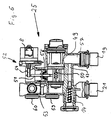
- Fig. 1 shown compact heating system is a gas boiler, as it is typically intended for wall mounting as a compact device for heat supply working with radiators space heating and for hot water / hot water production.
- a burner 1 acts on a primary heat exchanger 2, the heated water of a heat exchanger 3, typically in the form of one or more radiators for space heating, is supplied.
- the cooled water flows from the heat exchanger 3 back to the primary heat exchanger 2 and is circulated by means of a arranged on the cold side of the heat exchanger 2, 3 circulation pump 4.
- a plate heat exchanger 5 is provided, in which the coming from the water network cold hot water is heated. Since the heating of the service water has to be done only in the removal case, is appropriate sensors, in particular a flow meter 6 as well as a pressure and temperature sensor 7 is provided, depending on the output signal, a servomotor 8 is driven, which controls a 3/2-way valve 9, for the domestic water heating coming from the primary heat exchanger 2 heat-conducting liquid flow instead of the heat exchanger 3 to the plate heat exchanger 5 to redirect.
- a surge tank 10 is provided and a heat storage 11, which is connected in series between plate heat exchanger 5 and the primary heat exchanger 2, here on the cold side.
- Fig. 1 with 3 symbolized heat exchanger is, as usual today in hot water heating systems, provided with a thermostatic valve 12, which controls the circuit in terms of flow resistance and then, if no heat demand is given locks.
- a bypass line 13 is provided within the compact heating system with a valve 14, via which the hydraulically effective line cross section of the bypass line 13 is adjustable. Through this bypass line 13, a closed circulation circuit is ensured, even if the thermostatic valve 12 is fully closed.
- a safety valve 15 in the form of a pressure relief valve suction side of the pump 4 are provided and two shut-off valves 16 and 17, which are connected via a line 18 to each other.
- the heating system has a total of four line connections in the form of plug connections, namely a connection 19 for the heating flow as a port 20 for the heating return. Furthermore, there is a connection 21 provided for the domestic water inlet and a connection 22 for coming out of the plant hot water.
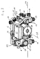
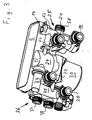
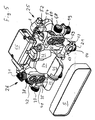
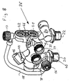
- FIG. 1 framed by broken lines part of the compact heating system is formed by a structural unit 23, the structure of the basis of FIGS. 2 to 9 is shown in detail.
- the assembly 23 is essentially composed of three injection-molded parts, namely a central, the pump housing-containing pump housing component 24, to the left in installation position seen from the front left a dashboard housing 25 and the right side a fitting housing 26.
- the components 24, 25 and 26 are fabricated as plastic injection molded components and designed to operate without the use of fused cores, i. H. can be manufactured with comparatively inexpensive tools that work with drawing cores.
- These components 24 to 26 are incorporated into each other in the transverse direction 27 to the impeller axis 28 of the pump and are positively secured by the rear-connected plate heat exchanger 5 in this position.
- the pump housing component 24 has the actual pump housing and a forwardly open insertion space 29, which is provided for receiving the pump impeller and for flanging the forward adjoining motor 30.
- the pump housing has an obliquely right above outgoing discharge nozzle 31, the free end is formed as a threaded connection and is provided for connection of the primary heat exchanger 2 leading line.
- an air separator 32 On the suction side connected to the pump housing or integrated into the pump housing component 24 is an air separator 32, in which a conventional Lucasabscheideventil is incorporated.
- the rearwardly directed suction mouth 33 of the pump is conductively connected to the valve housing 26 via a suction channel 34 extending in the transverse direction 27 into which it opens.
- the suction channel 34 continues in the fitting housing 26 continues to the right and opens into a rearwardly extending from the rear channel 35, which merges into a substantially cylindrically shaped, with its cylinder axis parallel to the impeller axis 28 and forward open insertion space 36, which serves as a central Anschussbasis for other connections or lines as well as for receiving fittings.
- a partition wall 39 is pressed into the insertion space 36 from the front.
- This partition wall 39 is formed by a simple sheet metal or a plastic part, since it does not depend on a complete seal to the insertion space 36 out.
- the terminals 37 and 38 are closed by blind caps, so they are out of order.
- the insertion space 36 opens from below a line 40, at the end of the connection 20 is arranged for the heating return.
- the bottom of the insertion space 36 is broken not only to the channel 35, but also in the upper left area (see Fig. 7 ), where a rear channel opens, which runs in alignment with a lower connecting piece 41, which is provided for connection of the plate heat exchanger 5.
- the connecting piece 41 is formed as a pair of connecting pieces together with the overlying connecting piece 42.
- the connecting piece 41 connects the Schuzierniklauf the heat exchanger 5 with the suction side of the pump 4.
- the upper connecting piece 42 connects the hot water leading service water connection of the heat exchanger 5 with a vertically downwardly leading channel 43, which opens into the connection 22 for hot service water.
- connection 66 is provided for the expansion tank 10 upwards.
- the insertion space 36 opens an obliquely coming from above and front receiving opening 44 which is provided at the end with a part of a bayonet fitting and in which a combined pressure and temperature sensor 45 is incorporated as a plug-in part, which is equipped with the other part of the bayonet closure ,
- the insertion space 36 itself serves to receive a Schmutzabscheiders 46, which is inserted in the manner of a sieve in this and arranged so that the coming of the terminal 20, ie from the heating return water must penetrate this before it reaches the suction channel 34 of the pump.
- the dirt separator 46 is held in a form-fitting manner and can be pulled out to the front for cleaning purposes.
- the insertion space 36 is provided towards the front with a bayonet closure, so that a corresponding lid can be placed without tools for the conclusion of the insertion space 36 and optionally removed again. It is understood that appropriate O-rings are provided as seals at the required locations.
- a safety valve 15 is incorporated in the lid 47 in the form of a pressure relief valve.
- the lid 47 forms part of the safety valve 15.
- each transverse channels are connected, which are closed by means of the shut-off valves 16 and 17. These channels are connected to each other via a line 18 which is formed as a separate component.
- the shut-off valve 16 can serve both to fill the system via the line 18 and the open valve 17 as well as for emptying the system after removal of the line 18 due to the horizontal nozzle.
- the conduit 18 is mounted so that it can be detached manually without tools, so that it can be removed or inserted as needed.
- This insertion space 48 serves to receive the 3/2-way valve 9, which is designed in the form of a slide-in fitting, which can be inserted from the front into the insertion space 48 and sealingly locked by means of a bayonet connection.
- the insertion space 48 final bayonet connection is identical to that for the insertion space 29 so that same end cover can be used.
- the insertion fitting 49 has, as best in Fig. 6 can be seen, two sealing seats, which are each closed by a sealing body.
- the sealing bodies are seated on a rod 50 arranged parallel to the rotor axis 28 and are aligned and arranged such that they always close in the direction of flow, whereby when moving the rod 50 in one direction the sealing body moves toward its sealing seat and the other is lifted off the latter or in the opposite direction in the reverse manner.
- the rod 50 is actuated by a lever 51, which is arranged pivotably in a mounting fitting 52, which is incorporated in an upwardly open insertion space 53, which has an opening to the insertion space 48.
- the lever 51 can engage with one end on the rod carrying the sealing body 50 and with its other end to a spindle 54 which is extended by a motor 8 depending on the rotational position more or less.
- the installation fitting 52 comprises the lever 51, the spindle 54 and the motor 8 and is inserted from above into the insertion space 53 with incorporation of an elastic and sealing cuff 56. This cuff seals the passage of the lever 51 without hindering its mobility.
- the installation fitting 52 may additionally be sealed by O-rings relative to the insertion space 53.
- lateral connections 58 on the left side or the connection formed by the pressure port 31 on the right side are arranged particularly advantageously, since the in installation insert from above lines to or from the primary heat exchanger 2 are easy to connect, since they spring in the transverse direction 27 over its entire length and therefore well manipulable, d. H. away from the connection or to the connection are movable.
- the insertion space 48 has on the bottom side an opening to a substantially coaxially extending back channel, in a connection piece 59 for the plate heat exchanger. 5 empties.
- This lower connecting piece 59 belongs to a pair whose upper connecting piece 60 is connected via a transverse channel 61 with a vertically downwardly extending channel 62, which opens into the port 21 for the service water inlet.
- the line connection 58 is conductively connected either to the lower connection piece 59 for the plate heat exchanger 5 or to the connection 19 for the heating flow.
- the insertion space 48 forms a connection base for almost all on this side of the pump leading channels.
- a channel 63 extending parallel to the rotor axis 28 adjoins the channel 63 which extends perpendicularly downwards to the connection 19 and together with the channel 64 running transversely thereto, opening into the channel region 63 and extending in the direction 27, the bypass line 13 forms.
- the transverse channel 64 opens in the lower rear region of the pump housing, ie in the suction chamber thereof, as in FIG Fig. 5 is clearly visible.
- a spring-loaded valve 14 is inserted from behind, through which the effective cross section of the bypass line 13 is pressure-dependent.
- On the vertical, leading to the port 21 channel 62 is a receptacle for a further pressure-temperature sensor 45 is provided to the front. Recording and sensor are formed in the same manner as that of the right fitting housing 26.
- This pressure / temperature sensor 45 which is inserted from the front, projects into the vertical and rear-side channel 62, which leads to the connection 21 for the service water inlet.
- the pressure sensor in conjunction with an obstruction formed in the channel 62 forms part of the flow meter 6 described in the introduction, in conjunction with a corresponding evaluation electronics, which is arranged in the terminal box 65.
- the terminal box 65 is provided, which is arranged on the housing of the motor 30 and thus associated with the pump housing component 24.
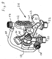
- the mechanical connection of the components 24, 25 and 26 takes place on the one hand via the channel connections (see Fig. 3 ) (34, 64) and on the other via corresponding, not described in detail here connecting webs, which are secured by means of threaded bolts.
- the channel connections are plug-in connections under inclusion of an O-ring, which performs the sealing function of the compound as well as a transversely inserted to the insertion direction U-shaped bracket, which takes over the mechanical lock.
- connections or connecting pieces described above are partially designed as plug-in connections, threaded connections or flange-like connection pieces.
- the respective designs are only to be understood as examples and can be adapted, exchanged or modified according to the requirements.
- the unit described above is extremely compact and is from the lateral dimensions approximately in alignment with the plate heat exchanger arranged rearwardly so that the entire unit between vertical struts of the chassis of the compact heating system is einliederbar, whereby the overall depth of the entire system can be reduced , Furthermore, all major units and fittings are accessible from the front or from the above the unit formed space so that they can be replaced and serviced without disassembly of the unit.
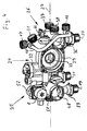
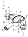
- the design of the pump housing component 24, in particular in the rear part results in detail from the Figures 10 and 11 as well as in the installed state from the Figures 3 and 5 ,
- the actual pump housing is stepped back and extends below the plate heat exchanger 5, where from the right (seen from the front) of the suction channel 34 and from the left of the transverse channel 64 connects to the bypass line 13.
- This the heat exchanger 5 on its underside superior part 75 of the pump housing is upstream of the actual suction chamber and forms part of an air separation, the actual separator 32 connects near the top and consists of a Lucasabscheidehunt 70 and this up closing vent valve 71.
- the suction chamber of the pump which is separated from the pressure chamber by a plate 72, opens into the suction mouth 33, which in its upper region is surrounded by an upper guide body 73 extending from the plate 72 backwards to the housing wall, approximately over 190 °. Downwardly at a distance, the suction mouth is surrounded by a lower guide body 74 which engages over the lower ends of the upper guide body 73 laterally and at a distance and also protrudes up to the rear housing wall of the pump housing component 24, specifically Fig. 10
- the arrangement of the guide body 73 and 74 is such that the flow entering from the suction channel 34 to the in. Under the plate heat exchanger 5 lying below the plate heat exchanger 5 Fig.
- bypass channel 64 also opens in the bottom of the suction chamber, under the lower guide body 74th
Landscapes
- Engineering & Computer Science (AREA)
- Mechanical Engineering (AREA)
- Physics & Mathematics (AREA)
- Thermal Sciences (AREA)
- Chemical & Material Sciences (AREA)
- Combustion & Propulsion (AREA)
- General Engineering & Computer Science (AREA)
- Water Supply & Treatment (AREA)
- Steam Or Hot-Water Central Heating Systems (AREA)
- Heat-Exchange Devices With Radiators And Conduit Assemblies (AREA)
- Structures Of Non-Positive Displacement Pumps (AREA)
- Basic Packing Technique (AREA)
- Yarns And Mechanical Finishing Of Yarns Or Ropes (AREA)
- Resistance Heating (AREA)
Claims (12)
- Module pour une installation de chauffage compacte, qui comprend un carter de pompe (24) et un dispositif de séparation d'air (32, 70, 71, 74, 75), et dans lequel un échangeur de chaleur à plaques (5) est raccordé au module, côté arrière en position de montage, et le carter de pompe (24) renferme au moins une partie du dispositif de séparation d'air (32, 70, 71, 74, 75), caractérisé en ce que, en position de montage, le carter de pompe (24) dépasse de l'échangeur de chaleur à plaques (5), au moins sur un côté, de telle sorte que l'espace au-dessus, au-dessous ou à côté de l'échangeur de chaleur à plaques est utilisé pour le carter de pompe.
- Module selon la revendication 1, caractérisé en ce que le carter de pompe (24) s'étend jusque sous l'échangeur de chaleur à plaques (5).
- Module selon l'une des revendications précédentes, caractérisé en ce que le carter de pompe (24) a la forme d'une tubulure dans la région de son extension.
- Module selon l'une des revendications précédentes, caractérisé en ce que le carter de pompe (24) a une forme en gradin sur son côté aspiration, la partie en gradin (25) étant disposée sous l'échangeur de chaleur à plaques (5).
- Module selon l'une des revendications précédentes, caractérisé en ce que la partie en gradin (75) du carter de pompe (24) qui est disposée sous l'échangeur de chaleur à plaques fait partie du dispositif de séparation d'air (32, 70, 71, 73, 74, 75).
- Module selon l'une des revendications précédentes, caractérisé en ce qu'il est prévu une soupape de ventilation (71) qui est disposée dans une chambre de séparation d'air (70) raccordée au carter de pompe (24), la chambre de séparation d'air (70) étant raccordée à la partie sans gradin du carter de pompe (24).
- Module selon l'une des revendications précédentes, caractérisé en ce qu'il est prévu à l'intérieur du carter de pompe (24) au moins un corps conducteur (73) qui entoure de préférence la partie inférieure de la bouche d'aspiration (33) de la pompe et s'étend jusque dans la partie en gradin (75) du carter de pompe qui est disposée sous l'échangeur de chaleur à plaques (5).
- Module selon l'une des revendications précédentes, caractérisé en ce qu'à l'intérieur du carter de pompe (24) est disposé un corps conducteur (74) qui entoure la partie supérieure de la bouche d'aspiration (33) de la pompe.
- Module selon l'une des revendications précédentes, caractérisé en ce que le corps conducteur supérieur (74) se termine en bas à l'intérieur de l'espace entouré par le corps conducteur inférieur (73).
- Module selon l'une des revendications précédentes, caractérisé en ce que la conduite côté aspiration (34) débouche dans la partie (75) du carter de pompe (24) qui s'étend sous l'échangeur de chaleur à plaques (5).
- Module selon l'une des revendications précédentes, caractérisé en ce qu'une conduite de dérivation (64) débouche dans la partie (75) du carter de pompe (24) qui s'étend sous l'échangeur de chaleur à plaques (5).
- Module selon l'une des revendications précédentes, caractérisé en ce que la conduite de dérivation (64) et la conduite d'aspiration (34) s'étendent parallèlement à l'échangeur de chaleur à plaques (5) et débouchent sur des côtés mutuellement opposés du carter de pompe (24).
Priority Applications (4)
| Application Number | Priority Date | Filing Date | Title |
|---|---|---|---|
| EP03025083A EP1528329B1 (fr) | 2003-11-03 | 2003-11-03 | Ensemble pour installation de chauffage compact |
| DE50313603T DE50313603D1 (de) | 2003-11-03 | 2003-11-03 | Baueinheit für eine Kompaktheizungsanlage |
| AT03025083T ATE504787T1 (de) | 2003-11-03 | 2003-11-03 | Baueinheit für eine kompaktheizungsanlage |
| CNB2004100883735A CN100513923C (zh) | 2003-11-03 | 2004-11-03 | 用于紧凑型供暖设备的组件单元 |
Applications Claiming Priority (1)
| Application Number | Priority Date | Filing Date | Title |
|---|---|---|---|
| EP03025083A EP1528329B1 (fr) | 2003-11-03 | 2003-11-03 | Ensemble pour installation de chauffage compact |
Publications (2)
| Publication Number | Publication Date |
|---|---|
| EP1528329A1 EP1528329A1 (fr) | 2005-05-04 |
| EP1528329B1 true EP1528329B1 (fr) | 2011-04-06 |
Family
ID=34400511
Family Applications (1)
| Application Number | Title | Priority Date | Filing Date |
|---|---|---|---|
| EP03025083A Expired - Lifetime EP1528329B1 (fr) | 2003-11-03 | 2003-11-03 | Ensemble pour installation de chauffage compact |
Country Status (4)
| Country | Link |
|---|---|
| EP (1) | EP1528329B1 (fr) |
| CN (1) | CN100513923C (fr) |
| AT (1) | ATE504787T1 (fr) |
| DE (1) | DE50313603D1 (fr) |
Cited By (3)
| Publication number | Priority date | Publication date | Assignee | Title |
|---|---|---|---|---|
| DE202014002654U1 (de) | 2014-03-27 | 2015-06-30 | Stiebel Eltron Gmbh & Co. Kg | Haustechnikgerät mit einem Abschluss für einen Energiewandler |
| DE202014002655U1 (de) | 2014-03-27 | 2015-06-30 | Stiebel Eltron Gmbh & Co. Kg | Wärmeenergiesystem mit einem Wärmeerzeuger und einem Behälter |
| EP3012553B1 (fr) | 2014-10-21 | 2018-01-17 | Grundfos Holding A/S | Composant pour une installation de chauffage |
Families Citing this family (11)
| Publication number | Priority date | Publication date | Assignee | Title |
|---|---|---|---|---|
| AT502650B1 (de) * | 2006-02-13 | 2007-05-15 | Vaillant Austria Gmbh | Aufnahmekörper in verbindung mit einer rohrleitung |
| ITBO20080456A1 (it) * | 2008-07-21 | 2010-01-22 | O T M A S N C Di Spaggiari & C | Gruppo idraulico valvolare per caldaie murali |
| EP2397777B1 (fr) * | 2010-06-19 | 2016-08-03 | Grundfos Management A/S | Unité de boîtier pour une installation de chauffage |
| EP2413045B1 (fr) | 2010-07-30 | 2014-02-26 | Grundfos Management A/S | Unité d'échange thermique |
| CN102818368B (zh) * | 2012-05-19 | 2014-10-29 | 威能(无锡)供热设备有限公司 | 附加器、燃气热水器、及附加器和燃气热水器组件 |
| EP2942583B1 (fr) * | 2014-05-06 | 2017-08-23 | O.T.M.A. S.N.C. di Spaggiari & C. | Corps de base monobloc pour un ensemble de vanne hydraulique pour utilisation dans une chaudière à montage mural |
| EP3012552B1 (fr) * | 2014-10-21 | 2018-01-31 | Grundfos Holding A/S | Composant pour une installation de chauffage compacte |
| JP6528903B2 (ja) * | 2016-04-11 | 2019-06-12 | 三菱電機株式会社 | 蓄熱装置 |
| CN106979612B (zh) * | 2017-04-28 | 2022-12-20 | 广东万和热能科技有限公司 | 壁挂炉 |
| TR202017937A2 (tr) * | 2020-11-10 | 2021-09-21 | Daikin Europe Nv | Hi̇droblok si̇stemleri̇ i̇çi̇n bi̇r güvenli̇k yapilandirmasi |
| WO2022269587A1 (fr) * | 2021-06-23 | 2022-12-29 | Chromagen Shaar Haamakim Ltd | Dispositifs modulaires entraînés par pompe à chaleur et procédés d'adaptation ultérieure pour systèmes de chauffe-eau domestique à thermosiphon |
Family Cites Families (5)
| Publication number | Priority date | Publication date | Assignee | Title |
|---|---|---|---|---|
| FR2755752B1 (fr) * | 1996-11-08 | 1999-02-05 | Aries | Module hydraulique pour installation de chauffage central et de production d'eau chaude, et chaudiere equipee d'un tel module |
| US6129523A (en) * | 1997-04-11 | 2000-10-10 | Ruhnke; John | Air purging circulator |
| DE19717799C5 (de) * | 1997-04-26 | 2007-02-08 | Grundfos A/S | Baueinheit für eine Kompaktheizungsanlage |
| IT1298069B1 (it) * | 1997-10-20 | 1999-12-20 | Valter Falavegna | Gruppo valvolare a distribuzione idraulica integrale particolarmente per caldaie murali da riscaldamento e produzione di acqua calda |
| IT1308197B1 (it) * | 1999-02-24 | 2001-12-10 | Fontecal S P A | Gruppo idraulico componibile. |
-
2003
- 2003-11-03 EP EP03025083A patent/EP1528329B1/fr not_active Expired - Lifetime
- 2003-11-03 AT AT03025083T patent/ATE504787T1/de active
- 2003-11-03 DE DE50313603T patent/DE50313603D1/de not_active Expired - Lifetime
-
2004
- 2004-11-03 CN CNB2004100883735A patent/CN100513923C/zh not_active Expired - Fee Related
Cited By (3)
| Publication number | Priority date | Publication date | Assignee | Title |
|---|---|---|---|---|
| DE202014002654U1 (de) | 2014-03-27 | 2015-06-30 | Stiebel Eltron Gmbh & Co. Kg | Haustechnikgerät mit einem Abschluss für einen Energiewandler |
| DE202014002655U1 (de) | 2014-03-27 | 2015-06-30 | Stiebel Eltron Gmbh & Co. Kg | Wärmeenergiesystem mit einem Wärmeerzeuger und einem Behälter |
| EP3012553B1 (fr) | 2014-10-21 | 2018-01-17 | Grundfos Holding A/S | Composant pour une installation de chauffage |
Also Published As
| Publication number | Publication date |
|---|---|
| EP1528329A1 (fr) | 2005-05-04 |
| ATE504787T1 (de) | 2011-04-15 |
| CN1619235A (zh) | 2005-05-25 |
| CN100513923C (zh) | 2009-07-15 |
| DE50313603D1 (de) | 2011-05-19 |
Similar Documents
| Publication | Publication Date | Title |
|---|---|---|
| EP1528330B1 (fr) | Ensemble pour installation de chauffage compact | |
| EP1528329B1 (fr) | Ensemble pour installation de chauffage compact | |
| EP2397777B1 (fr) | Unité de boîtier pour une installation de chauffage | |
| EP1884720B1 (fr) | Ensemble pour installation de chauffage compact | |
| DE2827022A1 (de) | Wasserbehaelter als reservedruckbehaelter | |
| DE10007873C1 (de) | Baueinheit für eine Kompaktheizungsanlage | |
| WO2007128304A2 (fr) | Module d'huile doté d'un conduit d'eau de refroidissement intégré | |
| EP1418387B1 (fr) | Installation de chauffage compacte avec deux circuits de chauffage | |
| EP0874201B2 (fr) | Ensemble pour installation de chauffage compact | |
| EP2093517B1 (fr) | Composant pour installation de chauffage compacte | |
| EP1884723B1 (fr) | Module | |
| EP1884717B1 (fr) | Appareil de chauffage | |
| DE19751515C2 (de) | Baueinheit für eine Kompaktheizungsanlage | |
| EP3012553B1 (fr) | Composant pour une installation de chauffage | |
| DE19912284A1 (de) | Kompaktheizungsanlage | |
| EP2093515B1 (fr) | Composant partiel pour une installation de chauffage compacte | |
| DE202015001818U1 (de) | Warmwasserspeicher mit zwei Behältern | |
| DE10041121B4 (de) | Wärmeübertrager mit mehreren Wärmeübertragungskreisen | |
| EP1528371B1 (fr) | Ensemble pour installation de chauffage compact | |
| EP1217310B1 (fr) | Unité compacte | |
| EP2629019B1 (fr) | Unité de boîtier pour un appareil de chauffage | |
| EP2093516B1 (fr) | Composant pour installation de chauffage compacte | |
| DE10050128A1 (de) | Filtervorrichtung | |
| EP1528328B1 (fr) | Module pour installation de chauffage compacte | |
| EP1014005A2 (fr) | Appareil pour l'installation de chauffage avec une vase de découplage et avec distributeur de circuit de chauffage |
Legal Events
| Date | Code | Title | Description |
|---|---|---|---|
| PUAI | Public reference made under article 153(3) epc to a published international application that has entered the european phase |
Free format text: ORIGINAL CODE: 0009012 |
|
| AK | Designated contracting states |
Kind code of ref document: A1 Designated state(s): AT BE BG CH CY CZ DE DK EE ES FI FR GB GR HU IE IT LI LU MC NL PT RO SE SI SK TR |
|
| AX | Request for extension of the european patent |
Extension state: AL LT LV MK |
|
| 17P | Request for examination filed |
Effective date: 20050405 |
|
| AKX | Designation fees paid |
Designated state(s): AT BE BG CH CY CZ DE DK EE ES FI FR GB GR HU IE IT LI LU MC NL PT RO SE SI SK TR |
|
| 17Q | First examination report despatched |
Effective date: 20051024 |
|
| GRAP | Despatch of communication of intention to grant a patent |
Free format text: ORIGINAL CODE: EPIDOSNIGR1 |
|
| GRAS | Grant fee paid |
Free format text: ORIGINAL CODE: EPIDOSNIGR3 |
|
| GRAA | (expected) grant |
Free format text: ORIGINAL CODE: 0009210 |
|
| AK | Designated contracting states |
Kind code of ref document: B1 Designated state(s): AT BE BG CH CY CZ DE DK EE ES FI FR GB GR HU IE IT LI LU MC NL PT RO SE SI SK TR |
|
| REG | Reference to a national code |
Ref country code: GB Ref legal event code: FG4D Free format text: NOT ENGLISH |
|
| REG | Reference to a national code |
Ref country code: CH Ref legal event code: EP |
|
| REG | Reference to a national code |
Ref country code: IE Ref legal event code: FG4D |
|
| REF | Corresponds to: |
Ref document number: 50313603 Country of ref document: DE Date of ref document: 20110519 Kind code of ref document: P |
|
| REG | Reference to a national code |
Ref country code: DE Ref legal event code: R096 Ref document number: 50313603 Country of ref document: DE Effective date: 20110519 |
|
| REG | Reference to a national code |
Ref country code: NL Ref legal event code: VDEP Effective date: 20110406 |
|
| PG25 | Lapsed in a contracting state [announced via postgrant information from national office to epo] |
Ref country code: SI Free format text: LAPSE BECAUSE OF FAILURE TO SUBMIT A TRANSLATION OF THE DESCRIPTION OR TO PAY THE FEE WITHIN THE PRESCRIBED TIME-LIMIT Effective date: 20110406 |
|
| REG | Reference to a national code |
Ref country code: IE Ref legal event code: FD4D |
|
| PG25 | Lapsed in a contracting state [announced via postgrant information from national office to epo] |
Ref country code: PT Free format text: LAPSE BECAUSE OF FAILURE TO SUBMIT A TRANSLATION OF THE DESCRIPTION OR TO PAY THE FEE WITHIN THE PRESCRIBED TIME-LIMIT Effective date: 20110808 Ref country code: SE Free format text: LAPSE BECAUSE OF FAILURE TO SUBMIT A TRANSLATION OF THE DESCRIPTION OR TO PAY THE FEE WITHIN THE PRESCRIBED TIME-LIMIT Effective date: 20110406 |
|
| PG25 | Lapsed in a contracting state [announced via postgrant information from national office to epo] |
Ref country code: GR Free format text: LAPSE BECAUSE OF FAILURE TO SUBMIT A TRANSLATION OF THE DESCRIPTION OR TO PAY THE FEE WITHIN THE PRESCRIBED TIME-LIMIT Effective date: 20110707 Ref country code: FI Free format text: LAPSE BECAUSE OF FAILURE TO SUBMIT A TRANSLATION OF THE DESCRIPTION OR TO PAY THE FEE WITHIN THE PRESCRIBED TIME-LIMIT Effective date: 20110406 Ref country code: CY Free format text: LAPSE BECAUSE OF FAILURE TO SUBMIT A TRANSLATION OF THE DESCRIPTION OR TO PAY THE FEE WITHIN THE PRESCRIBED TIME-LIMIT Effective date: 20110406 Ref country code: ES Free format text: LAPSE BECAUSE OF FAILURE TO SUBMIT A TRANSLATION OF THE DESCRIPTION OR TO PAY THE FEE WITHIN THE PRESCRIBED TIME-LIMIT Effective date: 20110717 |
|
| PG25 | Lapsed in a contracting state [announced via postgrant information from national office to epo] |
Ref country code: NL Free format text: LAPSE BECAUSE OF FAILURE TO SUBMIT A TRANSLATION OF THE DESCRIPTION OR TO PAY THE FEE WITHIN THE PRESCRIBED TIME-LIMIT Effective date: 20110406 |
|
| PG25 | Lapsed in a contracting state [announced via postgrant information from national office to epo] |
Ref country code: EE Free format text: LAPSE BECAUSE OF FAILURE TO SUBMIT A TRANSLATION OF THE DESCRIPTION OR TO PAY THE FEE WITHIN THE PRESCRIBED TIME-LIMIT Effective date: 20110406 Ref country code: CZ Free format text: LAPSE BECAUSE OF FAILURE TO SUBMIT A TRANSLATION OF THE DESCRIPTION OR TO PAY THE FEE WITHIN THE PRESCRIBED TIME-LIMIT Effective date: 20110406 Ref country code: IE Free format text: LAPSE BECAUSE OF FAILURE TO SUBMIT A TRANSLATION OF THE DESCRIPTION OR TO PAY THE FEE WITHIN THE PRESCRIBED TIME-LIMIT Effective date: 20110406 |
|
| PLBE | No opposition filed within time limit |
Free format text: ORIGINAL CODE: 0009261 |
|
| STAA | Information on the status of an ep patent application or granted ep patent |
Free format text: STATUS: NO OPPOSITION FILED WITHIN TIME LIMIT |
|
| PG25 | Lapsed in a contracting state [announced via postgrant information from national office to epo] |
Ref country code: SK Free format text: LAPSE BECAUSE OF FAILURE TO SUBMIT A TRANSLATION OF THE DESCRIPTION OR TO PAY THE FEE WITHIN THE PRESCRIBED TIME-LIMIT Effective date: 20110406 Ref country code: DK Free format text: LAPSE BECAUSE OF FAILURE TO SUBMIT A TRANSLATION OF THE DESCRIPTION OR TO PAY THE FEE WITHIN THE PRESCRIBED TIME-LIMIT Effective date: 20110406 Ref country code: RO Free format text: LAPSE BECAUSE OF FAILURE TO SUBMIT A TRANSLATION OF THE DESCRIPTION OR TO PAY THE FEE WITHIN THE PRESCRIBED TIME-LIMIT Effective date: 20110406 |
|
| 26N | No opposition filed |
Effective date: 20120110 |
|
| REG | Reference to a national code |
Ref country code: DE Ref legal event code: R097 Ref document number: 50313603 Country of ref document: DE Effective date: 20120110 |
|
| BERE | Be: lapsed |
Owner name: GRUNDFOS A/S Effective date: 20111130 |
|
| PG25 | Lapsed in a contracting state [announced via postgrant information from national office to epo] |
Ref country code: MC Free format text: LAPSE BECAUSE OF NON-PAYMENT OF DUE FEES Effective date: 20111130 |
|
| REG | Reference to a national code |
Ref country code: CH Ref legal event code: PL |
|
| PG25 | Lapsed in a contracting state [announced via postgrant information from national office to epo] |
Ref country code: CH Free format text: LAPSE BECAUSE OF NON-PAYMENT OF DUE FEES Effective date: 20111130 Ref country code: LI Free format text: LAPSE BECAUSE OF NON-PAYMENT OF DUE FEES Effective date: 20111130 |
|
| PG25 | Lapsed in a contracting state [announced via postgrant information from national office to epo] |
Ref country code: BE Free format text: LAPSE BECAUSE OF NON-PAYMENT OF DUE FEES Effective date: 20111130 |
|
| REG | Reference to a national code |
Ref country code: AT Ref legal event code: MM01 Ref document number: 504787 Country of ref document: AT Kind code of ref document: T Effective date: 20111103 |
|
| PG25 | Lapsed in a contracting state [announced via postgrant information from national office to epo] |
Ref country code: AT Free format text: LAPSE BECAUSE OF NON-PAYMENT OF DUE FEES Effective date: 20111103 |
|
| PG25 | Lapsed in a contracting state [announced via postgrant information from national office to epo] |
Ref country code: LU Free format text: LAPSE BECAUSE OF NON-PAYMENT OF DUE FEES Effective date: 20111103 |
|
| PG25 | Lapsed in a contracting state [announced via postgrant information from national office to epo] |
Ref country code: BG Free format text: LAPSE BECAUSE OF FAILURE TO SUBMIT A TRANSLATION OF THE DESCRIPTION OR TO PAY THE FEE WITHIN THE PRESCRIBED TIME-LIMIT Effective date: 20110706 |
|
| PG25 | Lapsed in a contracting state [announced via postgrant information from national office to epo] |
Ref country code: TR Free format text: LAPSE BECAUSE OF FAILURE TO SUBMIT A TRANSLATION OF THE DESCRIPTION OR TO PAY THE FEE WITHIN THE PRESCRIBED TIME-LIMIT Effective date: 20110406 |
|
| PG25 | Lapsed in a contracting state [announced via postgrant information from national office to epo] |
Ref country code: HU Free format text: LAPSE BECAUSE OF FAILURE TO SUBMIT A TRANSLATION OF THE DESCRIPTION OR TO PAY THE FEE WITHIN THE PRESCRIBED TIME-LIMIT Effective date: 20110406 |
|
| REG | Reference to a national code |
Ref country code: FR Ref legal event code: PLFP Year of fee payment: 14 |
|
| REG | Reference to a national code |
Ref country code: FR Ref legal event code: PLFP Year of fee payment: 15 |
|
| PGFP | Annual fee paid to national office [announced via postgrant information from national office to epo] |
Ref country code: IT Payment date: 20201130 Year of fee payment: 18 |
|
| PGFP | Annual fee paid to national office [announced via postgrant information from national office to epo] |
Ref country code: FR Payment date: 20211119 Year of fee payment: 19 Ref country code: GB Payment date: 20211123 Year of fee payment: 19 Ref country code: DE Payment date: 20211123 Year of fee payment: 19 |
|
| REG | Reference to a national code |
Ref country code: DE Ref legal event code: R119 Ref document number: 50313603 Country of ref document: DE |
|
| PG25 | Lapsed in a contracting state [announced via postgrant information from national office to epo] |
Ref country code: IT Free format text: LAPSE BECAUSE OF NON-PAYMENT OF DUE FEES Effective date: 20211130 |
|
| GBPC | Gb: european patent ceased through non-payment of renewal fee |
Effective date: 20221103 |
|
| PG25 | Lapsed in a contracting state [announced via postgrant information from national office to epo] |
Ref country code: GB Free format text: LAPSE BECAUSE OF NON-PAYMENT OF DUE FEES Effective date: 20221103 Ref country code: DE Free format text: LAPSE BECAUSE OF NON-PAYMENT OF DUE FEES Effective date: 20230601 |
|
| PG25 | Lapsed in a contracting state [announced via postgrant information from national office to epo] |
Ref country code: FR Free format text: LAPSE BECAUSE OF NON-PAYMENT OF DUE FEES Effective date: 20221130 |