EP0874201B2 - Ensemble pour installation de chauffage compact - Google Patents
Ensemble pour installation de chauffage compact Download PDFInfo
- Publication number
- EP0874201B2 EP0874201B2 EP98107184A EP98107184A EP0874201B2 EP 0874201 B2 EP0874201 B2 EP 0874201B2 EP 98107184 A EP98107184 A EP 98107184A EP 98107184 A EP98107184 A EP 98107184A EP 0874201 B2 EP0874201 B2 EP 0874201B2
- Authority
- EP
- European Patent Office
- Prior art keywords
- separator
- construction unit
- heating
- unit according
- dirt
- Prior art date
- Legal status (The legal status is an assumption and is not a legal conclusion. Google has not performed a legal analysis and makes no representation as to the accuracy of the status listed.)
- Expired - Lifetime
Links
- 238000010438 heat treatment Methods 0.000 title claims description 53
- 238000009434 installation Methods 0.000 title claims description 5
- XLYOFNOQVPJJNP-UHFFFAOYSA-N water Substances O XLYOFNOQVPJJNP-UHFFFAOYSA-N 0.000 claims description 19
- 230000005484 gravity Effects 0.000 claims description 2
- 238000010276 construction Methods 0.000 claims 12
- 238000013461 design Methods 0.000 description 4
- 239000007788 liquid Substances 0.000 description 4
- 238000004519 manufacturing process Methods 0.000 description 3
- 238000010348 incorporation Methods 0.000 description 2
- 238000002360 preparation method Methods 0.000 description 2
- 238000000926 separation method Methods 0.000 description 2
- 238000013022 venting Methods 0.000 description 2
- 240000006829 Ficus sundaica Species 0.000 description 1
- 238000011109 contamination Methods 0.000 description 1
- 238000011161 development Methods 0.000 description 1
- 230000018109 developmental process Effects 0.000 description 1
- 238000010586 diagram Methods 0.000 description 1
- 230000002349 favourable effect Effects 0.000 description 1
- 210000003746 feather Anatomy 0.000 description 1
- 238000002347 injection Methods 0.000 description 1
- 239000007924 injection Substances 0.000 description 1
- 238000012423 maintenance Methods 0.000 description 1
- 238000000034 method Methods 0.000 description 1
- 238000010079 rubber tapping Methods 0.000 description 1
- 230000008646 thermal stress Effects 0.000 description 1
Images

Classifications
-
- F—MECHANICAL ENGINEERING; LIGHTING; HEATING; WEAPONS; BLASTING
- F24—HEATING; RANGES; VENTILATING
- F24D—DOMESTIC- OR SPACE-HEATING SYSTEMS, e.g. CENTRAL HEATING SYSTEMS; DOMESTIC HOT-WATER SUPPLY SYSTEMS; ELEMENTS OR COMPONENTS THEREFOR
- F24D3/00—Hot-water central heating systems
- F24D3/10—Feed-line arrangements, e.g. providing for heat-accumulator tanks, expansion tanks ; Hydraulic components of a central heating system
- F24D3/105—Feed-line arrangements, e.g. providing for heat-accumulator tanks, expansion tanks ; Hydraulic components of a central heating system pumps combined with multiple way valves
-
- F—MECHANICAL ENGINEERING; LIGHTING; HEATING; WEAPONS; BLASTING
- F24—HEATING; RANGES; VENTILATING
- F24D—DOMESTIC- OR SPACE-HEATING SYSTEMS, e.g. CENTRAL HEATING SYSTEMS; DOMESTIC HOT-WATER SUPPLY SYSTEMS; ELEMENTS OR COMPONENTS THEREFOR
- F24D3/00—Hot-water central heating systems
- F24D3/08—Hot-water central heating systems in combination with systems for domestic hot-water supply
-
- F—MECHANICAL ENGINEERING; LIGHTING; HEATING; WEAPONS; BLASTING
- F24—HEATING; RANGES; VENTILATING
- F24D—DOMESTIC- OR SPACE-HEATING SYSTEMS, e.g. CENTRAL HEATING SYSTEMS; DOMESTIC HOT-WATER SUPPLY SYSTEMS; ELEMENTS OR COMPONENTS THEREFOR
- F24D19/00—Details
- F24D19/0095—Devices for preventing damage by freezing
-
- F—MECHANICAL ENGINEERING; LIGHTING; HEATING; WEAPONS; BLASTING
- F24—HEATING; RANGES; VENTILATING
- F24D—DOMESTIC- OR SPACE-HEATING SYSTEMS, e.g. CENTRAL HEATING SYSTEMS; DOMESTIC HOT-WATER SUPPLY SYSTEMS; ELEMENTS OR COMPONENTS THEREFOR
- F24D19/00—Details
- F24D19/08—Arrangements for drainage, venting or aerating
- F24D19/082—Arrangements for drainage, venting or aerating for water heating systems
- F24D19/083—Venting arrangements
- F24D19/085—Arrangement of venting valves for central heating radiators
- F24D19/087—Arrangement of venting valves for central heating radiators automatic
Definitions
- the invention relates to a structural unit for a compact heating system, in particular for a gas boiler with two heating circuits, one for space heating and one for hot water.
- Building units of this type are nowadays increasingly being installed in compact heating systems, in particular in gas water heaters or heating units. They include in addition to the centrifugal pump unit usually other components, such as air separator, safety valve, changeover valve and the like. They are called a structural unit, d. H. designed as a mounting and mounting unit, so that a simple and space-saving arrangement is ensured within the heating system. Moreover, such a unit is easy to assemble and maintain, since accessibility to the otherwise tight installation space must be ensured only in a few central locations and otherwise completely replaced in the case of repair and factory or elsewhere overhauled by the specialist and reuse can be supplied.
- An assembly comprising the features of the preamble of claim 1 is for example made EP 0 460 399 A2 known.
- This known unit is intended for a gas boiler, which includes two heating circuits, one for the hot water and one for space heating, both of which are supplied by a common gas-heated primary heat exchanger with heat.
- This known unit is provided for mounting in the flow of the primary heat exchanger and accordingly has an adjoining this flow inlet and two pressure ports, which are connected to the two heating circuits.
- this unit has an air separator, which is connected to a return flow through which the return lines of the heating circuits are passed through the assembly.
- a switching flap between the pump outlet and the two pressure ports is provided, which is controlled automatically depending on the direction of rotation of the impeller.
- the invention has the object, a generic unit for a compact heating system so that it can be operated reliably for a long time with low maintenance, continue to have the unit as compact as possible and be as inexpensive as possible in the production.
- This object is achieved according to the invention by the features listed in claim 1.
- Advantageous embodiments of the invention are specified in the subclaims and in the following description.
- An essential constructive feature of the invention is that, in addition to the air separator, a dirt separator is provided which removes the circulated within a flow deposits from the circulation and thus contributes to the reliability of the entire system, and in addition with an air separator in a common Housing is arranged, which is arranged positionally oriented. Namely, this housing having the dirt separator and the air separator must be arranged substantially vertically, so that the air can escape upwards and the dirt can escape downwards. Such a vertical arrangement in a common housing is also particularly favorable, since the main lines in this area, for example a gas boiler, run in the same direction, whereby only little installation space is claimed.
- the assembly according to the invention is also provided for incorporation in the return, which leads to a lower thermal stress on the components and, moreover, is less susceptible to cavitation-related noise developments.
- This incorporation in the return also ensures that dirt and air, which are carried out of the heating circuit (the radiators) are excreted before entering the centrifugal pump assembly and thus can not affect its function.
- a particularly compact structural unit is formed in that the switching element is arranged in the region between the dirt separator and the air separator, wherein according to the present invention, not both heating circuits are guided by dirt and air, but only provided for the space heating Heating circuit through the dirt separator and both heating circuits or one of these heating circuits through the air separator. Since both heating circuits are combined at least in the area of the primary heat exchanger, the separation of air and dirt in just one cycle is sufficient. It is expedient to arrange the dirt separator in the return of the heating circuit for space heating, since in this area, experience has shown that most often accumulates dirt. In order to prevent this dirt from entering the region of the switching element or the pump, the dirt separator is expediently arranged in front of it. Accordingly, the leading to the heating circuit for the space heating suction will advantageously connect laterally on the dirt trap.
- the switching element is arranged in the area between dirt and air separator. It is expedient to have the second suction nozzle, which leads to the heating circuit for hot water preparation, to be connected in the region of this switching element. With such an arrangement it is ensured that the water flowing back from both heating circuits is still supplied to the air separator before it reaches the pump unit.
- An air separation of both circuits may be appropriate, although it is basically sufficient to vent a circuit, namely the heating circuit for space heating.
- the additional venting of the heating circuit for hot water preparation by the air separator is particularly advantageous because a independent of the operation of the space heating vent is guaranteed. Such a constellation arises, for example, in summer, when the space heating is switched off and the system is only used for hot water.
- the lateral arrangement of the suction on the dirt trap and the air separator receiving housing is therefore advantageous because there is a good accessibility of the connections.
- the assembly is usually mounted so that the free end face of the engine faces forward, while the actual pump and the underlying components between the mounting wall and the engine are arranged. This area is narrow and difficult to access.
- the switching element is designed as a switching flap.
- an electromagnet for controlling the switching flap is integrated into the structural unit.
- this also allows the operation of the pump with high efficiency, since a reversal of direction is not required.
- centrifugal pump assembly is located next to the air separator, because then the exiting from the air separator liquid can be supplied to the pump on the shortest path.
- the dirt separator is designed as a cyclone separator, wherein a removable vessel should be provided on the underside of the housing, in which the dirt collects and which can be emptied.
- the air separator is advantageously designed as a gravity separator, so that the arrangement of the air separator at the upper end of the common housing supports its function and result in only short flow paths within the unit.
- connection between the suction mouth of the pump and air separator may be formed by an approximately radially arranged opening of the air separator, which opens into the suction port of the pump.
- the common housing are arranged in the dirt and air and separator and the switching element, allows an extremely space-saving design with short flow paths.
- further connections may be provided, for example for receiving an overflow valve and for receiving a pressure relief valve.
- the connection for the overflow valve is connected to the flow line of the boiler.
- the pressure relief valve opens either to the outside or is supplied via a hose to a drain line or a collecting vessel.
- heating system consists essentially of a gas-heated primary heat exchanger 1, a secondary heat exchanger 2 for hot water and a secondary heat exchanger 3 for space heating (radiator).
- the secondary heat exchangers 2, 3 form essential components of heating circuits, which are brought together in the region of the primary heat exchanger 1 and are controlled and circulated by a structural unit 4.
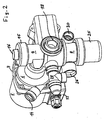
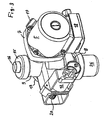
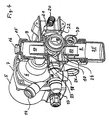
- the unit 4 is in the Fig. 2 to 4 shown in detail and includes a centrifugal pump assembly with an electric drive motor 5 and a driven centrifugal pump 6, which is connected via a flange 7 fixed to the electric motor 5.
- the assembly 4 includes a dirt separator 8 and an air separator 9 and a switching member 10 in the form of an electromagnetically controlled switching flap.
- the structural design of the unit 4 results in particular from the illustrations according to the Fig. 2 to 4 ,
- the electric motor has, as usual with pump units of this type, a substantially cylindrical housing with laterally mounted terminal box 13, in which the electrical connection cable is clamped.
- the centrifugal pump 6 is attached to the electric motor.
- the centrifugal pump has an approximately tangentially arranged discharge nozzle 14 and on the side facing away from the motor 5 a coaxial with the impeller axis arranged suction mouth.
- the suction port of the pump housing is extended and opens approximately tangentially in the cylindrical there formed air separator 9.
- the air separator is closed at its top by a screwed and sealed by a seal lid 15 having a central opening 16 which is for receiving a known Quick exhaust is provided.
- the air separator 9 is designed as a combined centrifugal and gravitational separator.
- the effluent from a central inner tube 17 liquid is deflected by 180 °, to then flow into the suction port of the pump 6. During this deflection process, the air is deposited upwards, where it escapes through the quick exhaust to the outside.
- the inner tube 17 opens into a provided under the air separator 9 chamber 18 in which the switching flap 10 is guided.
- this chamber 18 opens a suction nozzle 19 which is provided for connection of the return line of the secondary heat exchanger 2.
- the opening in the chamber 18 free end of the suction nozzle 19 is closed by the force of a spring 20 which acts in a lateral housing part, a lever 21, the other end of the switching valve 10 forms and this kraftbeaufschlagt and pressure-tight by an elastic wall 22 is.
- the lever 21 On the side facing away from the spring 20, the lever 21 is acted upon by the electromagnet 12 which, when actuated, moves the lever counter to the force of the spring 20 and moves the flap 10 such that the suction port 19 is connected to the chamber 18. In this position, a likewise opening into the chamber 18 channel 24 is closed or throttled.
- This channel 24 connects an inner tube 25 of the same under the chamber 18 to the air separator 9 arranged Schmutzabscheiders 8 with the chamber 18.
- the dirt separator 8 has a substantially cylindrical outer housing similar to that of the air separator 9, which is open at the bottom and can be closed by a screw-on cup-shaped container 25.
- the dirt separator 8 is designed as a cyclone separator, accordingly, an inlet opening is provided approximately tangentially in the cylindrical side wall, which is formed as a suction nozzle 26 of the assembly 4 and which is provided for connection of the coming from the secondary heat exchanger 3 return line.
- the substantially cylindrical housing of dirt separator 8 and 9 air separator is interrupted by the chamber surrounding the housing 18, wherein the entire common housing, which also includes the pump housing, integrally formed and is arranged vertically and transversely to the impeller axis.
- auxiliary nozzle 27 To the chamber 18 includes laterally (in Fig. 4 on the left side) to an auxiliary nozzle 27, in which a not shown in detail pressure relief valve 28 is screwed, the output of which flows into the open or can be discharged via a hose.
- auxiliary nozzle 29 is provided for connection to a line coming from the flow of the primary heat exchanger 1.
- the overflow valve whose operation and use are known per se (protection for boilers), is adjustable.
- an access opening 30 is laterally provided on the dirt separator 8, into which a tool can be inserted, with which the adjustment can be made.
- the above-described embodiment has a one-piece to the lid, container and other moving parts, made of injection molded housing, which is inexpensive to manufacture, especially in mass production and allows a very compact design.
Landscapes
- Engineering & Computer Science (AREA)
- Physics & Mathematics (AREA)
- Thermal Sciences (AREA)
- Chemical & Material Sciences (AREA)
- Combustion & Propulsion (AREA)
- Mechanical Engineering (AREA)
- General Engineering & Computer Science (AREA)
- Water Supply & Treatment (AREA)
- Structures Of Non-Positive Displacement Pumps (AREA)
- Separating Particles In Gases By Inertia (AREA)
- Jet Pumps And Other Pumps (AREA)
- Heat-Exchange Devices With Radiators And Conduit Assemblies (AREA)
Claims (10)
- Unité modulaire pour une installation de chauffage compacte, en particulier destinée à une chaudière à gaz, comprenant deux circuits de chauffage, l'un pour le chauffage de locaux et l'autre pour la préparation d'eau chaude, comportant:- un bloc moto-pompe centrifuge (5, 6),- un séparateur d'air (9),- un organe de commutation (10) pour alimenter l'un ou l'autre circuit de chauffage,- une première tubulure d'aspiration (19) et une deuxième tubulure d'aspiration (26), et- une tubulure de refoulement (14),caractérisée en ce- qu'il est prévu un séparateur d'impuretés (8) et que le séparateur d'impuretés (8) et le séparateur d'air (9) sont superposés dans un boîtier commun, dressé essentiellement verticalement et placé transversalement à l'axe du rotor du bloc moto-pompe centrifuge (5, 6),- que l'organe de commutation (10) est disposé dans la zone située entre le séparateur d'impuretés (8) et le séparateur d'air (9), et- que, pendant la marche de l'unité modulaire, l'eau provenant de l'un des circuits de chauffage arrive, au sein de l'unité modulaire, tout d'abord dans le séparateur d'impuretés (8), puis à travers l'organe de commutation (10) dans le séparateur d'air (9) et retourne, enfin, dans le circuit de chauffage par le biais du bloc motopompe centrifuge (5, 6).
- Unité modulaire selon la revendication 1, caractérisée en ce que la deuxième tubulure d'aspiration (26) conduisant au circuit de chauffage pour le chauffage de locaux, est raccordée latéralement au séparateur d'impuretés (8).
- Unité modulaire selon la revendication 1 ou 2, caractérisée en ce que la première tubulure d'aspiration (19), conduisant au circuit de chauffage pour la préparation d'eau chaude, est raccordée, dans la zone de l'organe de commutation (10), au boîtier recevant le séparateur d'impuretés (8) et le séparateur d'air (9).
- Unité modulaire selon l'une des revendications précédentes, caractérisée en ce que la tubulure de refoulement (14) est placé côté pompe centrifuge.
- Unité modulaire selon l'une des revendications précédentes, caractérisée en ce que l'organe de commutation est conçu en tant que clapet de commutation (10), à commande électromagnétique.
- Unité modulaire selon l'une des revendications précédentes, caractérisée en ce que le bloc moto-pompe centrifuge (5, 6) est placé à côté du séparateur d'air (9).
- Unité modulaire selon l'une des revendications précédentes, caractérisée en ce qu'au moins le séparateur d'impuretés (8) est conçu en tant que séparateur à cyclone.
- Unité modulaire selon l'une des revendications précédentes, caractérisée en ce que le séparateur d'air (9) est conçu en tant que séparateur par gravité.
- Unité modulaire selon l'une des revendications précédentes, caractérisée en ce que le boîtier présente, dans la zone du séparateur d'air (9), une ouverture latérale, qui est raccordée à l'embouchure d'aspiration (33) du bloc moto-pompe centrifuge (6).
- Unité modulaire selon l'une des revendications précédentes, caractérisée en ce que le séparateur d'impuretés (8) et le séparateur d'air (9) sont disposés à l'intérieur d'un boîtier (35) sensiblement cylindrique, aux deux côtés de celui-ci.
Applications Claiming Priority (2)
| Application Number | Priority Date | Filing Date | Title |
|---|---|---|---|
| DE19717799A DE19717799C5 (de) | 1997-04-26 | 1997-04-26 | Baueinheit für eine Kompaktheizungsanlage |
| DE19717799 | 1997-04-26 |
Publications (4)
| Publication Number | Publication Date |
|---|---|
| EP0874201A2 EP0874201A2 (fr) | 1998-10-28 |
| EP0874201A3 EP0874201A3 (fr) | 2000-05-24 |
| EP0874201B1 EP0874201B1 (fr) | 2004-02-18 |
| EP0874201B2 true EP0874201B2 (fr) | 2010-02-10 |
Family
ID=7827920
Family Applications (1)
| Application Number | Title | Priority Date | Filing Date |
|---|---|---|---|
| EP98107184A Expired - Lifetime EP0874201B2 (fr) | 1997-04-26 | 1998-04-21 | Ensemble pour installation de chauffage compact |
Country Status (2)
| Country | Link |
|---|---|
| EP (1) | EP0874201B2 (fr) |
| DE (2) | DE19717799C5 (fr) |
Cited By (1)
| Publication number | Priority date | Publication date | Assignee | Title |
|---|---|---|---|---|
| CN102777969A (zh) * | 2012-08-23 | 2012-11-14 | 普鲁卡姆电器(上海)有限公司 | 一种自适应壁挂式外排双气源燃气取暖器 |
Families Citing this family (15)
| Publication number | Priority date | Publication date | Assignee | Title |
|---|---|---|---|---|
| DE19751515C2 (de) * | 1997-11-21 | 1999-12-02 | Grundfos A S Bjerringbro | Baueinheit für eine Kompaktheizungsanlage |
| DE19912284B4 (de) * | 1999-03-18 | 2012-10-18 | Grundfos A/S | Kompaktheizungsanlage |
| DE19923936A1 (de) * | 1999-05-26 | 2000-11-30 | Wilo Gmbh | Ventil mit auswechselbarem Absperrkörper |
| DE20005247U1 (de) | 2000-03-21 | 2000-05-25 | Grundfos A/S, Bjerringbro | Kreiselpumpenaggregat |
| EP1217310B1 (fr) | 2000-12-22 | 2006-06-14 | Grundfos A/S | Unité compacte |
| DE50313603D1 (de) * | 2003-11-03 | 2011-05-19 | Grundfos As | Baueinheit für eine Kompaktheizungsanlage |
| EP1580489B9 (fr) | 2004-03-22 | 2009-09-02 | Grundfos A/S | Unité pour installation de chauffage compacte |
| CN100451450C (zh) * | 2006-05-16 | 2009-01-14 | 南京普鲁卡姆电器有限公司 | 双气源燃气取暖器 |
| DE102008052884A1 (de) * | 2008-10-23 | 2010-05-06 | Wilo Se | Pumpengehäuse |
| EP2397777B1 (fr) | 2010-06-19 | 2016-08-03 | Grundfos Management A/S | Unité de boîtier pour une installation de chauffage |
| CN102777966B (zh) * | 2012-08-23 | 2014-11-26 | 普鲁卡姆电器(上海)有限公司 | 一种自适应式气电双工双气源燃气取暖器 |
| EP2708825B1 (fr) | 2012-09-12 | 2016-12-07 | Grundfos Holding A/S | Procédé de commande d'une pompe de recirculation dans une installation avec au moins deux circuits |
| EP3438556A1 (fr) * | 2017-08-03 | 2019-02-06 | Grundfos Holding A/S | Dispositif de mélange, système de chauffage avec dispositif de mélange et procédé |
| SK9474Y1 (sk) * | 2021-06-13 | 2022-04-13 | Protherm Production S.R.O. | Hydraulický modul pre vykurovacie zariadenie s tepelným čerpadlom |
| WO2024260596A1 (fr) * | 2023-06-21 | 2024-12-26 | Grundfos Holding A/S | Soupape de mélangeur/déflecteur |
Citations (5)
| Publication number | Priority date | Publication date | Assignee | Title |
|---|---|---|---|---|
| DE1653725A1 (de) † | 1967-09-29 | 1972-01-13 | Hanning Elektro Werke | Umwaelzpumpe fuer Heizungsanlagen |
| US4756475A (en) † | 1986-03-07 | 1988-07-12 | Elettro Termica Sud S.P.A. | Gas-fired boiler |
| DE3813654A1 (de) † | 1988-04-22 | 1989-11-02 | Licentia Gmbh | Umwaelzpumpe |
| EP0363586A1 (fr) † | 1988-09-20 | 1990-04-18 | WILO GmbH | Appareil pour séparer du gaz |
| DE4127822A1 (de) † | 1991-08-23 | 1993-02-25 | Grundfos Int | Gastherme |
Family Cites Families (6)
| Publication number | Priority date | Publication date | Assignee | Title |
|---|---|---|---|---|
| DE543770C (de) * | 1927-02-19 | 1932-02-09 | Harry Sauveur Dipl Ing | Vorrichtung zur Reinhaltung der Saugoeffnung von unter dem Fluessigkeitsspiegel arbeitenden Pumpen von Gas und Sand |
| US4072481A (en) * | 1976-04-09 | 1978-02-07 | Laval Claude C | Device for separating multiple phase fluid systems according to the relative specific gravities of the phase |
| US4940473A (en) * | 1989-06-16 | 1990-07-10 | Benham Roger A | Cyclone solids separator and de-gasifier |
| EP0460399B1 (fr) * | 1990-05-04 | 1994-08-31 | Grundfos International A/S | Pompe centrifuge et chaudière à gaz avec une telle pompe |
| SE510471C2 (sv) * | 1994-11-17 | 1999-05-25 | Bjoern Carlsson | Förfarande och anordning för att hämma uppkkomsten av korrosion i en ledningskrets för en kontinuerligt strömmande systemvätska |
| DE19717883C2 (de) * | 1997-03-22 | 2000-05-11 | Reiner Waese | Reinigungsgerät für eine Flüssigkeit, insbesondere in geschlossenen Kreisläufen und Verfahren zum Reinigen einer Flüssigkeit |
-
1997
- 1997-04-26 DE DE19717799A patent/DE19717799C5/de not_active Expired - Lifetime
-
1998
- 1998-04-21 EP EP98107184A patent/EP0874201B2/fr not_active Expired - Lifetime
- 1998-04-21 DE DE59810771T patent/DE59810771D1/de not_active Expired - Lifetime
Patent Citations (5)
| Publication number | Priority date | Publication date | Assignee | Title |
|---|---|---|---|---|
| DE1653725A1 (de) † | 1967-09-29 | 1972-01-13 | Hanning Elektro Werke | Umwaelzpumpe fuer Heizungsanlagen |
| US4756475A (en) † | 1986-03-07 | 1988-07-12 | Elettro Termica Sud S.P.A. | Gas-fired boiler |
| DE3813654A1 (de) † | 1988-04-22 | 1989-11-02 | Licentia Gmbh | Umwaelzpumpe |
| EP0363586A1 (fr) † | 1988-09-20 | 1990-04-18 | WILO GmbH | Appareil pour séparer du gaz |
| DE4127822A1 (de) † | 1991-08-23 | 1993-02-25 | Grundfos Int | Gastherme |
Cited By (2)
| Publication number | Priority date | Publication date | Assignee | Title |
|---|---|---|---|---|
| CN102777969A (zh) * | 2012-08-23 | 2012-11-14 | 普鲁卡姆电器(上海)有限公司 | 一种自适应壁挂式外排双气源燃气取暖器 |
| CN102777969B (zh) * | 2012-08-23 | 2014-12-10 | 普鲁卡姆电器(上海)有限公司 | 一种自适应壁挂式外排双气源燃气取暖器 |
Also Published As
| Publication number | Publication date |
|---|---|
| DE59810771D1 (de) | 2004-03-25 |
| EP0874201A2 (fr) | 1998-10-28 |
| DE19717799C5 (de) | 2007-02-08 |
| DE19717799C2 (de) | 2003-03-20 |
| EP0874201A3 (fr) | 2000-05-24 |
| EP0874201B1 (fr) | 2004-02-18 |
| DE19717799A1 (de) | 1998-10-29 |
Similar Documents
| Publication | Publication Date | Title |
|---|---|---|
| EP0874201B2 (fr) | Ensemble pour installation de chauffage compact | |
| DE19809123B4 (de) | Wasserpumpe für den Kühlkreislauf einer Brennkraftmaschine | |
| EP2397777B1 (fr) | Unité de boîtier pour une installation de chauffage | |
| EP1528330B1 (fr) | Ensemble pour installation de chauffage compact | |
| EP0460399B1 (fr) | Pompe centrifuge et chaudière à gaz avec une telle pompe | |
| EP1528329B1 (fr) | Ensemble pour installation de chauffage compact | |
| EP1130342B2 (fr) | Module pour installation de chauffage compacte | |
| EP1418387B1 (fr) | Installation de chauffage compacte avec deux circuits de chauffage | |
| EP1884720B1 (fr) | Ensemble pour installation de chauffage compact | |
| EP0529353B1 (fr) | Chaudière à gaz | |
| EP0918197B2 (fr) | Ensemble pour installation de chauffage compact | |
| EP0218031B1 (fr) | Pompe centrifuge | |
| DE102012012551A1 (de) | Lüftungsanordnung mit einer Dunstabzugshaube | |
| EP1884723B1 (fr) | Module | |
| EP0791772A2 (fr) | Soupape à trois voies pour jonction hydraulique | |
| EP1316347B1 (fr) | Filtre à liquide pour purifier du carburant | |
| EP1033495B1 (fr) | Adapteur pour circuit de chauffage ou de refroidissement | |
| EP2944825B1 (fr) | Boîtier de pompe doté de trois brides | |
| EP2072823B1 (fr) | Pompe centrifuge dotée d'une déaération | |
| EP2629019B1 (fr) | Unité de boîtier pour un appareil de chauffage | |
| EP1217310B1 (fr) | Unité compacte | |
| EP2093516B1 (fr) | Composant pour installation de chauffage compacte | |
| EP1884717A1 (fr) | Appareil de chauffage | |
| EP1055826B1 (fr) | Soupape avec piéce de fermeture remplaçable | |
| DE8527065U1 (de) | Kreiselpumpe |
Legal Events
| Date | Code | Title | Description |
|---|---|---|---|
| PUAI | Public reference made under article 153(3) epc to a published international application that has entered the european phase |
Free format text: ORIGINAL CODE: 0009012 |
|
| AK | Designated contracting states |
Kind code of ref document: A2 Designated state(s): DE FR GB IT |
|
| AX | Request for extension of the european patent |
Free format text: AL;LT;LV;MK;RO;SI |
|
| PUAL | Search report despatched |
Free format text: ORIGINAL CODE: 0009013 |
|
| AK | Designated contracting states |
Kind code of ref document: A3 Designated state(s): AT BE CH CY DE DK ES FI FR GB GR IE IT LI LU MC NL PT SE |
|
| AX | Request for extension of the european patent |
Free format text: AL;LT;LV;MK;RO;SI |
|
| 17P | Request for examination filed |
Effective date: 20000608 |
|
| AKX | Designation fees paid |
Free format text: DE FR GB IT |
|
| 17Q | First examination report despatched |
Effective date: 20011130 |
|
| GRAP | Despatch of communication of intention to grant a patent |
Free format text: ORIGINAL CODE: EPIDOSNIGR1 |
|
| GRAS | Grant fee paid |
Free format text: ORIGINAL CODE: EPIDOSNIGR3 |
|
| GRAA | (expected) grant |
Free format text: ORIGINAL CODE: 0009210 |
|
| AK | Designated contracting states |
Kind code of ref document: B1 Designated state(s): DE FR GB IT |
|
| REG | Reference to a national code |
Ref country code: GB Ref legal event code: FG4D Free format text: NOT ENGLISH |
|
| REF | Corresponds to: |
Ref document number: 59810771 Country of ref document: DE Date of ref document: 20040325 Kind code of ref document: P |
|
| GBT | Gb: translation of ep patent filed (gb section 77(6)(a)/1977) |
Effective date: 20040408 |
|
| PLBQ | Unpublished change to opponent data |
Free format text: ORIGINAL CODE: EPIDOS OPPO |
|
| ET | Fr: translation filed | ||
| PLBI | Opposition filed |
Free format text: ORIGINAL CODE: 0009260 |
|
| PLAX | Notice of opposition and request to file observation + time limit sent |
Free format text: ORIGINAL CODE: EPIDOSNOBS2 |
|
| 26 | Opposition filed |
Opponent name: WILO AG Effective date: 20041117 |
|
| PLBB | Reply of patent proprietor to notice(s) of opposition received |
Free format text: ORIGINAL CODE: EPIDOSNOBS3 |
|
| RDAF | Communication despatched that patent is revoked |
Free format text: ORIGINAL CODE: EPIDOSNREV1 |
|
| APBP | Date of receipt of notice of appeal recorded |
Free format text: ORIGINAL CODE: EPIDOSNNOA2O |
|
| APAH | Appeal reference modified |
Free format text: ORIGINAL CODE: EPIDOSCREFNO |
|
| APBQ | Date of receipt of statement of grounds of appeal recorded |
Free format text: ORIGINAL CODE: EPIDOSNNOA3O |
|
| APBU | Appeal procedure closed |
Free format text: ORIGINAL CODE: EPIDOSNNOA9O |
|
| PUAH | Patent maintained in amended form |
Free format text: ORIGINAL CODE: 0009272 |
|
| STAA | Information on the status of an ep patent application or granted ep patent |
Free format text: STATUS: PATENT MAINTAINED AS AMENDED |
|
| 27A | Patent maintained in amended form |
Effective date: 20100210 |
|
| AK | Designated contracting states |
Kind code of ref document: B2 Designated state(s): DE FR GB IT |
|
| REG | Reference to a national code |
Ref country code: FR Ref legal event code: PLFP Year of fee payment: 19 |
|
| REG | Reference to a national code |
Ref country code: FR Ref legal event code: PLFP Year of fee payment: 20 |
|
| PGFP | Annual fee paid to national office [announced via postgrant information from national office to epo] |
Ref country code: FR Payment date: 20170224 Year of fee payment: 20 |
|
| PGFP | Annual fee paid to national office [announced via postgrant information from national office to epo] |
Ref country code: IT Payment date: 20170308 Year of fee payment: 20 |
|
| PGFP | Annual fee paid to national office [announced via postgrant information from national office to epo] |
Ref country code: GB Payment date: 20170427 Year of fee payment: 20 Ref country code: DE Payment date: 20170426 Year of fee payment: 20 |
|
| REG | Reference to a national code |
Ref country code: DE Ref legal event code: R071 Ref document number: 59810771 Country of ref document: DE |
|
| REG | Reference to a national code |
Ref country code: GB Ref legal event code: PE20 Expiry date: 20180420 |
|
| PG25 | Lapsed in a contracting state [announced via postgrant information from national office to epo] |
Ref country code: GB Free format text: LAPSE BECAUSE OF EXPIRATION OF PROTECTION Effective date: 20180420 |