EP1528371B1 - Ensemble pour installation de chauffage compact - Google Patents
Ensemble pour installation de chauffage compact Download PDFInfo
- Publication number
- EP1528371B1 EP1528371B1 EP03025082A EP03025082A EP1528371B1 EP 1528371 B1 EP1528371 B1 EP 1528371B1 EP 03025082 A EP03025082 A EP 03025082A EP 03025082 A EP03025082 A EP 03025082A EP 1528371 B1 EP1528371 B1 EP 1528371B1
- Authority
- EP
- European Patent Office
- Prior art keywords
- assembly
- openings
- connection
- water
- obstruction
- Prior art date
- Legal status (The legal status is an assumption and is not a legal conclusion. Google has not performed a legal analysis and makes no representation as to the accuracy of the status listed.)
- Expired - Lifetime
Links
- 238000010438 heat treatment Methods 0.000 title claims abstract description 63
- 238000009434 installation Methods 0.000 title claims description 9
- XLYOFNOQVPJJNP-UHFFFAOYSA-N water Substances O XLYOFNOQVPJJNP-UHFFFAOYSA-N 0.000 claims abstract description 105
- 239000004033 plastic Substances 0.000 claims abstract description 3
- 239000000523 sample Substances 0.000 claims description 22
- 238000002347 injection Methods 0.000 claims description 4
- 239000007924 injection Substances 0.000 claims description 4
- 238000005259 measurement Methods 0.000 claims 1
- 238000001746 injection moulding Methods 0.000 description 7
- 238000000034 method Methods 0.000 description 6
- 238000004519 manufacturing process Methods 0.000 description 4
- 230000001914 calming effect Effects 0.000 description 3
- 238000010276 construction Methods 0.000 description 3
- 239000012530 fluid Substances 0.000 description 3
- 238000003780 insertion Methods 0.000 description 3
- 230000037431 insertion Effects 0.000 description 3
- 230000015572 biosynthetic process Effects 0.000 description 2
- 238000013461 design Methods 0.000 description 2
- 238000001514 detection method Methods 0.000 description 2
- 238000011156 evaluation Methods 0.000 description 2
- 239000008236 heating water Substances 0.000 description 2
- 238000002844 melting Methods 0.000 description 2
- 230000008018 melting Effects 0.000 description 2
- 230000001419 dependent effect Effects 0.000 description 1
- 238000000605 extraction Methods 0.000 description 1
- 230000004927 fusion Effects 0.000 description 1
- 239000002991 molded plastic Substances 0.000 description 1
- 239000007787 solid Substances 0.000 description 1
- 238000012549 training Methods 0.000 description 1
Images
Classifications
-
- G—PHYSICS
- G01—MEASURING; TESTING
- G01F—MEASURING VOLUME, VOLUME FLOW, MASS FLOW OR LIQUID LEVEL; METERING BY VOLUME
- G01F15/00—Details of, or accessories for, apparatus of groups G01F1/00 - G01F13/00 insofar as such details or appliances are not adapted to particular types of such apparatus
- G01F15/005—Valves
-
- F—MECHANICAL ENGINEERING; LIGHTING; HEATING; WEAPONS; BLASTING
- F24—HEATING; RANGES; VENTILATING
- F24H—FLUID HEATERS, e.g. WATER OR AIR HEATERS, HAVING HEAT-GENERATING MEANS, e.g. HEAT PUMPS, IN GENERAL
- F24H1/00—Water heaters, e.g. boilers, continuous-flow heaters or water-storage heaters
- F24H1/48—Water heaters for central heating incorporating heaters for domestic water
- F24H1/52—Water heaters for central heating incorporating heaters for domestic water incorporating heat exchangers for domestic water
-
- F—MECHANICAL ENGINEERING; LIGHTING; HEATING; WEAPONS; BLASTING
- F24—HEATING; RANGES; VENTILATING
- F24H—FLUID HEATERS, e.g. WATER OR AIR HEATERS, HAVING HEAT-GENERATING MEANS, e.g. HEAT PUMPS, IN GENERAL
- F24H9/00—Details
- F24H9/14—Arrangements for connecting different sections, e.g. in water heaters
- F24H9/142—Connecting hydraulic components
-
- G—PHYSICS
- G01—MEASURING; TESTING
- G01F—MEASURING VOLUME, VOLUME FLOW, MASS FLOW OR LIQUID LEVEL; METERING BY VOLUME
- G01F1/00—Measuring the volume flow or mass flow of fluid or fluent solid material wherein the fluid passes through a meter in a continuous flow
- G01F1/05—Measuring the volume flow or mass flow of fluid or fluent solid material wherein the fluid passes through a meter in a continuous flow by using mechanical effects
- G01F1/20—Measuring the volume flow or mass flow of fluid or fluent solid material wherein the fluid passes through a meter in a continuous flow by using mechanical effects by detection of dynamic effects of the flow
- G01F1/32—Measuring the volume flow or mass flow of fluid or fluent solid material wherein the fluid passes through a meter in a continuous flow by using mechanical effects by detection of dynamic effects of the flow using swirl flowmeters
- G01F1/325—Means for detecting quantities used as proxy variables for swirl
- G01F1/3259—Means for detecting quantities used as proxy variables for swirl for detecting fluid pressure oscillations
-
- G—PHYSICS
- G01—MEASURING; TESTING
- G01F—MEASURING VOLUME, VOLUME FLOW, MASS FLOW OR LIQUID LEVEL; METERING BY VOLUME
- G01F15/00—Details of, or accessories for, apparatus of groups G01F1/00 - G01F13/00 insofar as such details or appliances are not adapted to particular types of such apparatus
- G01F15/18—Supports or connecting means for meters
- G01F15/185—Connecting means, e.g. bypass conduits
Definitions
- the invention relates to a structural unit for a compact heating system, in particular for a gas boiler.
- Such compact heating systems are used for heating of heating water for space heating and heating of process water.
- a large number of individual components is combined in a common compact housing. While in older constructions, the individual elements have been connected to each other via pipes, which was relatively expensive, has been going on for some time increasingly to perform the entire piping complex with the required fittings including receptacles for individual units such as pump, valves and the like as a unit, which usually are made of one or more injection molded plastic parts.
- Such a unit forms an integrated water cycle, which contains in particular the connections for the space heating circuit and for the Brauchiganzu- and removal, the required valves and a circulation pump.
- Such a structural unit is known, for example, from EP 1 130 341 A2.
- a flow sensor For the domestic water heating a flow sensor is required, which detects the flow in the hot water circuit or the service water, whether hot water is requested in order to then activate the burner and the circulation pump to heat the hot water can.
- a flow sensor is known for example from JP 54-161968 or US 4,718,283.
- Such a flow sensor must be connected via flanged connections with the hot water pipes in the compact heating system, which increases the number of items and assembly steps in the installation of the compact heating system.
- the structural unit according to the invention for a compact heating system has at least one line for hot water to be heated.
- a heat exchanger such as a plate heat exchanger, mounted in which the hot water is heated via the heating circuit.
- the cold service water via a corresponding line in the assembly to the heat exchanger and discharged via a further line in the assembly of the plate heat exchanger.
- connections for the domestic water and hot water outlet are preferably present on the unit to connect the compact heating system with appropriate cold and hot water pipes of domestic installation.
- the service water line in the interior of the unit has at least one line section, in which a flow sensor with an obstruction and a measuring probe is arranged.
- Such a flow sensor acts in such a way that through the obstruction in the conduit vortices are generated in the flow, which are measured by means of the measuring probe.
- the probe detects in the vortex generated by the obstruction pressure differences or pressure frequencies from which the flow velocity can be determined at a known size of the obstruction.
- a sensor structure is known, for example, from EP 02 028 959.
- the Measuring probe formed a receptacle or opening.
- the obstruction is preferably formed in the interior of the line section in one piece with this by injection molding.
- an opening is provided according to the invention at two opposite ends of the line section, so that the line section can be formed by means of two pull cores.
- the line section is therefore preferably formed in each case at least between the openings and the obstruction in its longitudinal direction without undercuts.
- the drawing cores can be pulled out after the injection molding of the assembly with the line section through the openings.
- the obstruction during injection molding of the plastic assembly can be integrally formed in the conduit section for the service water supply without requiring expensive fusion cores.
- the production of the unit can be simplified and the manufacturing cost of the unit and thus the compact heating system can be reduced.
- the conduit section extends straight at least between one of the openings and the obstruction.
- the drawing core can be pulled out to form this line section in a linear movement in the longitudinal direction of the straight line section through the opening.
- the straight course of the line section also allows optimal flow of the obstruction to ensure safe operation of the flow sensor for detecting the hot water demand.
- the entire line section between the two opposite openings straight.
- the obstruction can be easily formed by two linearly movable in the longitudinal direction of the line section drawing cores. This favors in particular the formation of a symmetrical with respect to the longitudinal axis of the line section obstruction.
- one of the openings in the line section simultaneously serves as a connection for a service water line, preferably for the heated process water.
- a service water line preferably for the heated process water.
- the number of required openings in the unit is reduced.
- the number of openings, which are needed only for the production, but not in the subsequent operation of the assembly is reduced.
- the one opening which is needed to form the obstruction in the interior of the line section by means of a pulling core not be subsequently closed, since it then serves later as a service water connection.
- the opening in this line section fulfills two functions.
- one of the openings is designed to be closed. If one or both of the openings for the formation of obstruction are not needed in later operation, they can be closed by appropriate plugs or closures. Preferably, however, at least one of the openings for connecting the line section is used with external lines, so that only one of the openings must be closed.
- one of the openings can serve as a connection for filling a heating circuit. That means to the Opening a line is connected or connectable, which is connected to the heating circuit.
- at least one valve is provided in this line in order to be able to open the line in a targeted manner in order to introduce service water from the line section of the service water circuit into the space heating heating circuit in order to fill the space heating circuit with water.
- the line between the hot water circuit and the heating circuit can be fixed or removable. If the conduit is solid, it is preferably also integrated into the assembly. Characterized in that the one opening for the drawing core to form the obstruction in the interior of the line section is used in operation as a connection for filling a heating circuit, it is not necessary to close this opening.
- a filling line or a valve is connected to the opening.
- one of the two openings at the opposite ends of the line section connection for filling the heating circuit and the other opening is used as a connection for a service water pipe.
- the first of the openings to an underside and the second of the openings directed to an upper side of the assembly corresponds to the position of the unit in the assembled state of the compact heating system.
- the assembly is usually arranged so that a mounted on the unit heat exchanger, in particular plate heat exchanger is arranged horizontally.
- the arrangement of the openings at the top and bottom of the assembly allows that the injection cores are supplied from two opposite sides, preferably along the same axis in opposite directions and removed from the finished molded unit can. In this way, a long and preferably straight channel can be formed, which extends through the entire structural unit.
- This embodiment has the advantage that the line section in which the obstruction is formed can be made as long as possible in order to have a sufficiently long calming section for the flow, and to be able to generate targeted vortices for the flow sensor in the flow by means of the obstruction.
- the line section, which extends between the openings, preferably extends over the entire width or height of the unit, so that at given outer dimensions of the unit of the existing space is optimally utilized to create the longest possible line section for receiving the flow sensor.
- the line section runs in the installed position of the unit in the vertical direction.
- the openings are preferably freely accessible at the top and bottom of the assembly, so that they can either be easily closed or connected to the desired attachments and / or external lines.
- one of the openings is arranged on the underside of the structural unit and serves as a connection for a service water pipe.
- all connections of the compact heating system are arranged in a plane at the bottom of the unit. These are the connections for the hot water supply and the heated service water as well as the two connections for the space heating circuit.
- the line section with the flow sensor thus preferably extends from the upper side of the unit to the lower end of the unit and serves for the discharge of heated service water from the heat exchanger, in which the service water is heated, to the hot water connection at the bottom of the unit.
- the arranged in this line section flow sensor detects the service water flow and, where appropriate, their speed when service water is requested by opening a faucet on a line connected to the unit.
- the conduit section further preferably has a port for connection to a heat exchanger in the vicinity of one of the two openings, preferably in the vicinity of the upper opening.
- the connection for connection to a heat exchanger is designed as an opening or as a further integrated into the assembly line section, which establishes the connection to an attached to the unit heat exchanger.
- This connection opening is preferably arranged in the vicinity of the upper opening of the described line section.
- the heat exchanger is attached to the back of the unit, wherein the output for the hot water to be heated is located near the top of the unit.
- the service water inlet of the heat exchanger can be arranged at the top and connected to the line section with the flow sensor. Then the flow sensor is in the service water inlet instead, as described above, in the process water drain.
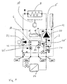
- FIG. 1 shows a schematic representation of the construction of a compact heating system with the structural unit 2 according to the invention, the components of which are delimited by dashed lines in FIG. All arranged inside the dashed boundary components are integrated into the unit.
- the assembly essentially has nine connections for connection to external pipelines or components. These are the connections CHF and CHR for the space heating circuit, the connection DCW for the supply of cold service water and the connection DHW for the heated service water.
- the unit has ports 4 and 6 for connection of the primary heat exchanger 8 in the heating boiler. In the primary heat exchanger 8, the water is heated in the primary circuit via a burner 10, preferably a gas burner.
- a connection 12 for a compensating vessel and two connections 14 and 16 for connecting a water reservoir 18 for storing heated water in the primary circuit are provided on the structural unit 2.
- a pump 20, a 2/3-way valve 22 and a secondary heat exchanger 24 are arranged in a known manner as essential components.
- the fluid or water which is pumped by the pump 20, flows from the pump 20 through the connection 6 to the primary heat exchanger and via the connection 4 back into the assembly 2.
- the 2/3-way valve which can switch the primary circuit between the secondary heat exchanger 24 and the connection CHF for space heating.
- the 2/3-way valve 22 is switched to space heating, the water flows through the connection CHF through the radiator in the rooms to be heated back to the connection CHR to the unit 2 and back to the suction side of the pump 20.
- the water flows in the primary circuit of the 2/3-way valve through the preferably designed as a plate heat exchanger secondary heat exchanger 24 and from there via the terminal 16 through the water tank 18 and the port At the same time, the service water to be heated is passed through the secondary heat exchanger 24 via the connections DHW and DCW and heated there via the primary circuit.
- the water reservoir 18 which is formed as an insulated tank, a certain amount of the heated fluid or water of the primary circuit is cached to allow a faster hot water heating.
- the 2/3-way valve is switched to domestic water heating at intervals of operation of the compact heating system, even if no hot water is taken from us.
- heated water is supplied to the water reservoir 18 by the primary heat exchanger 8 and stored there. This process can be started, for example, via a temperature sensor provided in the water reservoir 18. If now hot water is removed, this is detected by a flow sensor 26.
- the pump 20 is put into operation together with the switching of the 2/3-way valve 22 to hot water, so that stored in the water tank 18 warm heating water from the pump 20 through the primary heat exchanger. 8 and the 2/3-way valve 22 is supplied to the secondary heat exchanger 24.
- domestic water can already be heated in the secondary heat exchanger 24 before the boiler with the burner 10 reaches its operating temperature for heating the primary circuit via the primary heat exchanger 8.
- the water tank 18 shown in the present example is not absolutely necessary, but the terminals 14 and 16 could also be short-circuited or non-existent, that is, the output side of the secondary heat exchanger 24 may be connected directly to the suction side of the pump 20.
- the other components of the assembly 2 correspond to the arrangements of known units for compact heating systems, which is why a more detailed explanation is omitted here.
- space heating circuit which is indicated in Fig. 1 only by a heat exchanger or radiator 27 with associated valve, preferably thermostatic valve, corresponds to conventional arrangements of heating circuits with one or more heat exchangers or radiators.
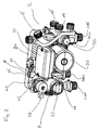
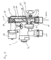
- FIG. 2 shows an overall perspective view of the assembly according to the invention.
- the pump 20 is arranged centrally.
- the 2/3-way valve 22 is arranged, which is actuated via a servomotor 28.
- a line section is formed with a receptacle 30 for a dirt separator.
- the connections CHF, CHR, DHW and DCW are designed to connect the heating circuit or the hot water pipes to the compact heating system.
- a terminal box 32 for connection of the pump and for receiving electronic components is arranged.
- the secondary heat exchanger 24 is mounted in the form of a plate heat exchanger.
- the connection 4 and on the pressure side of the pump 20, the connection 6 for connection to the primary heat exchanger 8 (not shown here) is formed.
- the assembly includes all line sections or components of the fluid circuits between the externally connected primary heat exchanger 8 and the connections CHF, CHR, DHW and DCW for the space heating circuit and the service water supply.
- the ports 14 and 16 for a water reservoir for storing heated water of the primary circuit are arranged in the receiving housing 30 for the dirt separator.
- the terminals 14 and 16 are formed as a threaded connection piece integral with the terminal housing 30.
- the entire assembly 2 is integrally formed as an injection molded part.
- the assembly may be composed of individual housing components.
- the housing part with the receiving housing 30, the housing part for receiving the pump 20 and the housing part for receiving the 2/3-way valve are manufactured as separate components by injection molding and then assembled to the unit 2.
- connection DHW for heated service water is in connection with a line section or channel 34, which extends from the bottom of the assembly, starting from the connection DHW vertically up to the top of the unit 2.
- the upper end side of the channel 34 has at its upper end facing away from the terminal DHW an opening 36 which is closed by a closure element 38.
- Below the opening 36 branches off substantially at right angles from the channel 34 from a connecting channel 40, which establishes the connection of the channel 34 to a port 42 of the secondary heat exchanger 24.
- the heated service water exits the secondary heat exchanger 24 and into the connecting channel 40 a.
- a measuring probe 44 of the flow sensor 26 is inserted into the channel 34.
- the measuring probe 44 is a combined pressure / temperature sensor, which can determine both a pressure or pressure differences and the temperature in the brewing water flowing through the channel 34.
- the detection of the temperature of the heated service water is needed to control the hot water heating, in particular for controlling the burner 10 in the process water heating.
- the pressure sensor of the measuring probe 44 forms part of the flow sensor 26, which detects a flow in the channel 34. When a flow is detected in the channel 34, it means that a faucet for the extraction of heated service water is opened, so that there is a request for heated water.
- the control unit of the compact heating system turns on the burner 10 and the pump 20 and the 2/3-way valve 22 on domestic water heating. Even if a measuring probe 44 is used as a combined temperature and pressure sensor in the present case, the temperature sensor is not absolutely necessary. Thus, the temperature sensor can also be designed as a separate sensor and arranged at a different location than the measuring probe 44 in the structural unit 2.
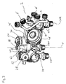
- Fig. 3 shows a view of the assembly 2 according to FIG. 2, wherein the secondary heat exchanger 24, the pump 20 with the terminal box 32 and the 2/3-way valve 22 removed from the assembly 2 and removed from this. Furthermore, the dirt separator is removed from the receiving housing 30.
- the insertion housing 46 is formed for the pump 20 with the suction port 48 of the pump 20. Above the insertion space or housing 46 is connected to the suction port 48, an air separator 50 on the suction side of the pump 20 is arranged. As can be seen in Fig. 3, extends at the back of the unit 2 before the secondary heat exchanger 24 (see Fig. 2) of the channel 34 perpendicular substantially over the entire height of the unit 2.
- the connecting channel 40 can be formed by a further pulling core which can be removed through an opening 52 at the end of the connecting channel 40 facing away from the channel 34.
- the opening 52 is also closed by removal of the pulling core by a closure element.
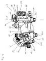
- Fig. 4 shows the assembly of FIG. 2 viewed from the rear side. From the rear, the four ports 42, 54, 56 and 58 can be seen for the secondary heat exchanger 24.
- the connection 54 is also essentially perpendicular through the unit 2 extending channel connected to the DCW connection for cold service water. In this way, the service water to be heated from the port DCW via the channel 60 and the port 54 in the secondary heat exchanger 24 (not shown in Fig. 4) is initiated.
- the heated service water exits the secondary heat exchanger at the port 42 and flows from there inside the unit 2 through the connecting channel 40 and the channel 34 to the DHW, to which the dwelling or house-side hot water pipe is connected to the compact heating system.
- connection 58 the water of the heating circuit is passed from the 2/3-way valve 22 in the secondary heat exchanger 24 for heating the service water.
- the water of the heating circuit exits the secondary heat exchanger at the connection 56 and flows from there inside the assembly 2 into the receiving housing 30 and from there via the channel 62 into the insertion housing 46 to the suction mouth 48 of the pump 20th
- the flow sensor 26 is arranged consisting of a flow resistance or an obstruction 62 and the measuring probe 44.
- the obstruction 62 is made in one piece with the channel 34 or the assembly 2 by injection molding.
- the obstruction extends rod-shaped diametrically through the channel 34 and has, for example, a triangular cross-section.
- the exact structure of the flow sensor consisting of obstruction 62 and measuring probe 44 and in particular the geometric dimensions and the arrangement of measuring probe 44 and obstruction 62 are known from EP 02 028 959.1.
- the measuring probe 44 protrudes into the flow channel 34, so that your pressure transducer 64 is arranged substantially centrally in the channel 34.
- the measuring probe 44 preferably has pressure sensors on two opposite sides in order to be able to detect pressure differences in the interior of the channel 34.
- the measuring probe 44 with the Pressure sensor 64 is arranged in the flow direction S behind the obstruction 62. Due to the flow in the channel 34, in the flow direction S behind the obstruction 62, vortices which are detected by the measuring probe 44 are produced.
- the measuring probe 44 detects pressures or, in particular, their change frequencies via the pressure transducer 64, from which, with known dimensions, the flow velocity in the interior of the channel 34 can be concluded.
- the corresponding metrological evaluation is carried out by an evaluation electronics connected to the measuring probe 44, which can be arranged, for example, in the terminal box 32.
- the measuring probe 44 is inserted through an opening 66 from the front into the channel 34.
- the described straight configuration of the channel 34 wherein the channel 34 extends substantially from the top to the bottom of the assembly 2 over its entire height, has the advantage that the channel 34 can be formed as long as possible, so before the obstruction 62 a as long as possible calming section is created in which the flow can calm down or stabilize before it reaches the flow sensor 26 formed from obstruction 62 and measuring probe 44.
- the straight and smooth configuration of the channel 34 with the openings 36 and 68 formed at its opposite ends allows for easy manufacture of the channel 34 with the obstruction 62 integrally formed therein.
- the opening 36 is closed in later operation by a closure element 38.
- openings can be used for the drawing cores, which must be provided for operation anyway in the assembly 2, so that the number of openings to be closed after the injection molding is minimized.
- the opening 36 for connecting other components such as a filling line or a filling valve for filling the heating circuit with water could be arranged.
- channel 34 is straight from port 36 to port DHW, channel 34 could also be angled or curved.
- the channel 34 may be formed according to the invention by drawing cores, it is only necessary that no undercuts are formed in the channel 34 between the obstruction 62 and the openings 36 and 68, so that after injection molding the drawing cores are pulled out of the openings 36 and 68 can.
- the channel in an angled configuration, could be rectilinear from the obstruction 62 to the opening 38 and the opening 68, respectively, with the conduit portion between the obstruction 62 and the opening 36 being angled to the conduit portion between the obstruction 62 and the opening 68.
- curved drawing cores which can be pulled out along apertures 38 and 68 along correspondingly curved paths, could be used.
- the openings 66 and the connecting channel 40, which communicate with the channel 34, can be formed by further drawing cores.
Landscapes
- Engineering & Computer Science (AREA)
- Physics & Mathematics (AREA)
- Combustion & Propulsion (AREA)
- Thermal Sciences (AREA)
- Chemical & Material Sciences (AREA)
- General Physics & Mathematics (AREA)
- Fluid Mechanics (AREA)
- Mechanical Engineering (AREA)
- General Engineering & Computer Science (AREA)
- Steam Or Hot-Water Central Heating Systems (AREA)
- Basic Packing Technique (AREA)
- Yarns And Mechanical Finishing Of Yarns Or Ropes (AREA)
- Resistance Heating (AREA)
- Instantaneous Water Boilers, Portable Hot-Water Supply Apparatuses, And Control Of Portable Hot-Water Supply Apparatuses (AREA)
Claims (10)
- Unité modulaire pour une installation de chauffage compacte, en particulier pour une chaudière à gaz, l'unité modulaire (2) étant réalisée sous forme d'un élément en matière plastique moulé par injection et formant un circuit d'eau intégré, qui comporte les raccords pour le circuit de chauffage de locaux (CHF, CHR) ainsi que pour l'arrivée et le départ d'eau sanitaire (DCW, DHW), une vanne à 2/3 voies (22), un échangeur de chaleur secondaire (24) et une pompe de recirculation (20), étant précisé que dans l'unité modulaire (2) est disposé au moins un conduit pour de l'eau sanitaire à échauffer, qui présente au moins un tronçon de conduit (34), dans lequel est disposé un détecteur de débit (26), caractérisée en ce que le détecteur de débit comprend un obstacle (62) et une sonde de mesure (44) et en ce qu'à deux extrémités, opposées l'une à l'autre, du tronçon de conduit (34), est respectivement prévue une ouverture (36, 68), et le tronçon de conduit, au moins entre les ouvertures (36, 68) et l'obstacle, est configuré d'une manière telle, qu'il puisse être réalisé au moyen de deux noyaux coulissants.
- Unité modulaire selon la revendication 1, caractérisée en ce que le tronçon de conduit (34), au moins entre l'une des ouvertures (36, 68) et l'obstacle (62), se développe sous une allure rectiligne.
- Unité modulaire selon la revendication 1 ou 2, caractérisée en ce que le tronçon de conduit (34) se développe sous une allure rectiligne entre les deux ouvertures (36, 68) opposées l'une à l'autre.
- Unité modulaire selon l'une des revendications précédentes, caractérisée en ce que l'une des ouvertures (68) sert en même temps de raccord (DHW) pour un conduit d'eau sanitaire, de préférence pour l'eau sanitaire échauffée.
- Unité modulaire selon l'une des revendications précédentes, caractérisée en ce que l'une des ouvertures (36) est obturée.
- Unité modulaire selon l'une des revendications précédentes, caractérisée en ce que l'une des ouvertures (36) peut servir de raccord pour le remplissage d'un circuit de chauffage.
- Unité modulaire selon l'une des revendications précédentes, caractérisée en ce que dans la position de montage de l'unité modulaire (2), la première des ouvertures (68) est dirigée vers un côté inférieur et la seconde des ouvertures (36) est dirigée vers un côté supérieur de l'unité modulaire (2).
- Unité modulaire selon l'une des revendications précédentes, caractérisée en ce que le tronçon de conduit (34) s'étend en direction verticale (X) dans la position de montage de l'unité modulaire (2).
- Unité modulaire selon l'une des revendications précédentes, caractérisée en ce que l'une des ouvertures (68) est située sur le côté inférieur de l'unité modulaire (2) et peut servir de raccord (DHW) pour un conduit d'eau sanitaire.
- Unité modulaire selon l'une des revendications précédentes, caractérisée en ce qu'au voisinage de l'une des deux ouvertures (36, 68), de préférence au voisinage de l'ouverture supérieure (36), le tronçon de conduit (34) présente un raccord (42), pour être relié à un échangeur de chaleur (24).
Priority Applications (3)
| Application Number | Priority Date | Filing Date | Title |
|---|---|---|---|
| DE50306804T DE50306804D1 (de) | 2003-11-03 | 2003-11-03 | Baueinheit für eine Kompaktheizungsanlage |
| AT03025082T ATE356974T1 (de) | 2003-11-03 | 2003-11-03 | Baueinheit für eine kompaktheizungsanlage |
| EP03025082A EP1528371B1 (fr) | 2003-11-03 | 2003-11-03 | Ensemble pour installation de chauffage compact |
Applications Claiming Priority (1)
| Application Number | Priority Date | Filing Date | Title |
|---|---|---|---|
| EP03025082A EP1528371B1 (fr) | 2003-11-03 | 2003-11-03 | Ensemble pour installation de chauffage compact |
Publications (2)
| Publication Number | Publication Date |
|---|---|
| EP1528371A1 EP1528371A1 (fr) | 2005-05-04 |
| EP1528371B1 true EP1528371B1 (fr) | 2007-03-14 |
Family
ID=34400510
Family Applications (1)
| Application Number | Title | Priority Date | Filing Date |
|---|---|---|---|
| EP03025082A Expired - Lifetime EP1528371B1 (fr) | 2003-11-03 | 2003-11-03 | Ensemble pour installation de chauffage compact |
Country Status (3)
| Country | Link |
|---|---|
| EP (1) | EP1528371B1 (fr) |
| AT (1) | ATE356974T1 (fr) |
| DE (1) | DE50306804D1 (fr) |
Families Citing this family (4)
| Publication number | Priority date | Publication date | Assignee | Title |
|---|---|---|---|---|
| ITPD20090018A1 (it) * | 2009-01-29 | 2010-07-30 | Italtecnica S R L | Dispositivo di raccordo particolarmente per gruppi autoclave ad elettropompa |
| DE102009038745A1 (de) * | 2009-08-27 | 2011-03-03 | Wilo Se | Baueinheit für einen Fluidkreislauf |
| EP2489951B1 (fr) * | 2011-02-21 | 2017-04-05 | Gerdes OHG | Chauffe-eau instantané électrique |
| EP2613097B2 (fr) | 2012-01-09 | 2020-11-18 | Grundfos Holding A/S | Appareil de chauffage |
Family Cites Families (7)
| Publication number | Priority date | Publication date | Assignee | Title |
|---|---|---|---|---|
| JPS54161968A (en) * | 1978-06-12 | 1979-12-22 | Yokogawa Hokushin Electric Corp | Production of flow velocity and flow rate measuring device |
| US4718283A (en) * | 1987-01-30 | 1988-01-12 | Itt Corporation | Vortex meter body |
| GB2250334B (en) * | 1990-11-21 | 1994-09-07 | Imi Range Ltd | Waterheating apparatus |
| DE19636360C2 (de) * | 1996-09-06 | 2001-05-23 | Bosch Gmbh Robert | Verfahren zur Brauchwasserbereitstellung in einem kombinierten System |
| DK0841545T3 (da) * | 1996-11-08 | 1999-11-08 | Flowtec Ag | Hvirvelstrømsdetektor |
| IT1308197B1 (it) * | 1999-02-24 | 2001-12-10 | Fontecal S P A | Gruppo idraulico componibile. |
| DE10007924A1 (de) * | 2000-02-21 | 2001-08-23 | Wilo Gmbh | Anschlußvorrichtung für eine Heizungspumpe |
-
2003
- 2003-11-03 EP EP03025082A patent/EP1528371B1/fr not_active Expired - Lifetime
- 2003-11-03 DE DE50306804T patent/DE50306804D1/de not_active Expired - Lifetime
- 2003-11-03 AT AT03025082T patent/ATE356974T1/de not_active IP Right Cessation
Also Published As
| Publication number | Publication date |
|---|---|
| ATE356974T1 (de) | 2007-04-15 |
| DE50306804D1 (de) | 2007-04-26 |
| EP1528371A1 (fr) | 2005-05-04 |
Similar Documents
| Publication | Publication Date | Title |
|---|---|---|
| EP1884720B1 (fr) | Ensemble pour installation de chauffage compact | |
| EP1967714B1 (fr) | Régulateur d'agent de refroidissement et son procédé de fabrication | |
| EP2397777A1 (fr) | Unité de boîtier pour une installation de chauffage | |
| EP2613097B1 (fr) | Appareil de chauffage | |
| EP1528330A1 (fr) | Ensemble pour installation de chauffage compact | |
| EP2312224B1 (fr) | Pompe à chaleur dotée d'un module hydraulique | |
| EP1528329B1 (fr) | Ensemble pour installation de chauffage compact | |
| DE202006018615U1 (de) | Einsatz für einen Warmwasser-Schichtspeicher | |
| WO1998008029A1 (fr) | Armoire monolithique d'accumulation de chaleur | |
| DE102007019389B4 (de) | Formwerkzeugtemperiersystem, Vorrichtung mit Formwerkzeugtemperiersystem und Verfahren zum Temperieren einer Vorrichtung sowie zur Herstellung der Vorrichtung | |
| EP1528371B1 (fr) | Ensemble pour installation de chauffage compact | |
| EP1939539B1 (fr) | Dispositif destiné à alimenter des circuits haute et basse consommation d'énergie | |
| EP1884723B1 (fr) | Module | |
| EP2093517B1 (fr) | Composant pour installation de chauffage compacte | |
| EP1418387B1 (fr) | Installation de chauffage compacte avec deux circuits de chauffage | |
| EP1884717B1 (fr) | Appareil de chauffage | |
| DE102005058570B3 (de) | Verfahren zur Warmwasserbereitung mit einem Wärmeerzeuger und einem Schichtladespeicher | |
| EP2428748B1 (fr) | Radiateur à panneaux et procédé de conduite d'un produit de chauffage | |
| EP2093515B1 (fr) | Composant partiel pour une installation de chauffage compacte | |
| EP2827077B1 (fr) | Accumulateur d'eau chaude | |
| EP0630463B2 (fr) | Chauffe-eau electrique instantane | |
| EP1528328B1 (fr) | Module pour installation de chauffage compacte | |
| DE19830307C2 (de) | Heizkörperventil für Heizungsanlagen | |
| WO2010135755A2 (fr) | Chauffe-eau | |
| DE102007042232A1 (de) | Wärmetauscher und Verfahren zum Herstellen und Betreiben |
Legal Events
| Date | Code | Title | Description |
|---|---|---|---|
| PUAI | Public reference made under article 153(3) epc to a published international application that has entered the european phase |
Free format text: ORIGINAL CODE: 0009012 |
|
| 17P | Request for examination filed |
Effective date: 20041023 |
|
| AK | Designated contracting states |
Kind code of ref document: A1 Designated state(s): AT BE BG CH CY CZ DE DK EE ES FI FR GB GR HU IE IT LI LU MC NL PT RO SE SI SK TR |
|
| AX | Request for extension of the european patent |
Extension state: AL LT LV MK |
|
| AKX | Designation fees paid |
Designated state(s): AT BE BG CH CY CZ DE DK EE ES FI FR GB GR HU IE IT LI LU MC NL PT RO SE SI SK TR |
|
| GRAP | Despatch of communication of intention to grant a patent |
Free format text: ORIGINAL CODE: EPIDOSNIGR1 |
|
| GRAS | Grant fee paid |
Free format text: ORIGINAL CODE: EPIDOSNIGR3 |
|
| GRAA | (expected) grant |
Free format text: ORIGINAL CODE: 0009210 |
|
| AK | Designated contracting states |
Kind code of ref document: B1 Designated state(s): AT BE BG CH CY CZ DE DK EE ES FI FR GB GR HU IE IT LI LU MC NL PT RO SE SI SK TR |
|
| PG25 | Lapsed in a contracting state [announced via postgrant information from national office to epo] |
Ref country code: FI Free format text: LAPSE BECAUSE OF FAILURE TO SUBMIT A TRANSLATION OF THE DESCRIPTION OR TO PAY THE FEE WITHIN THE PRESCRIBED TIME-LIMIT Effective date: 20070314 Ref country code: NL Free format text: LAPSE BECAUSE OF FAILURE TO SUBMIT A TRANSLATION OF THE DESCRIPTION OR TO PAY THE FEE WITHIN THE PRESCRIBED TIME-LIMIT Effective date: 20070314 Ref country code: SI Free format text: LAPSE BECAUSE OF FAILURE TO SUBMIT A TRANSLATION OF THE DESCRIPTION OR TO PAY THE FEE WITHIN THE PRESCRIBED TIME-LIMIT Effective date: 20070314 Ref country code: IE Free format text: LAPSE BECAUSE OF FAILURE TO SUBMIT A TRANSLATION OF THE DESCRIPTION OR TO PAY THE FEE WITHIN THE PRESCRIBED TIME-LIMIT Effective date: 20070314 |
|
| REG | Reference to a national code |
Ref country code: GB Ref legal event code: FG4D Free format text: NOT ENGLISH |
|
| REG | Reference to a national code |
Ref country code: CH Ref legal event code: EP |
|
| REF | Corresponds to: |
Ref document number: 50306804 Country of ref document: DE Date of ref document: 20070426 Kind code of ref document: P |
|
| REG | Reference to a national code |
Ref country code: IE Ref legal event code: FG4D Free format text: LANGUAGE OF EP DOCUMENT: GERMAN |
|
| GBT | Gb: translation of ep patent filed (gb section 77(6)(a)/1977) |
Effective date: 20070517 |
|
| PG25 | Lapsed in a contracting state [announced via postgrant information from national office to epo] |
Ref country code: SE Free format text: LAPSE BECAUSE OF FAILURE TO SUBMIT A TRANSLATION OF THE DESCRIPTION OR TO PAY THE FEE WITHIN THE PRESCRIBED TIME-LIMIT Effective date: 20070614 |
|
| PG25 | Lapsed in a contracting state [announced via postgrant information from national office to epo] |
Ref country code: BG Free format text: LAPSE BECAUSE OF EXPIRATION OF PROTECTION Effective date: 20070615 |
|
| PG25 | Lapsed in a contracting state [announced via postgrant information from national office to epo] |
Ref country code: ES Free format text: LAPSE BECAUSE OF FAILURE TO SUBMIT A TRANSLATION OF THE DESCRIPTION OR TO PAY THE FEE WITHIN THE PRESCRIBED TIME-LIMIT Effective date: 20070625 |
|
| PG25 | Lapsed in a contracting state [announced via postgrant information from national office to epo] |
Ref country code: PT Free format text: LAPSE BECAUSE OF FAILURE TO SUBMIT A TRANSLATION OF THE DESCRIPTION OR TO PAY THE FEE WITHIN THE PRESCRIBED TIME-LIMIT Effective date: 20070814 |
|
| NLV1 | Nl: lapsed or annulled due to failure to fulfill the requirements of art. 29p and 29m of the patents act | ||
| ET | Fr: translation filed | ||
| REG | Reference to a national code |
Ref country code: IE Ref legal event code: FD4D |
|
| PG25 | Lapsed in a contracting state [announced via postgrant information from national office to epo] |
Ref country code: SK Free format text: LAPSE BECAUSE OF FAILURE TO SUBMIT A TRANSLATION OF THE DESCRIPTION OR TO PAY THE FEE WITHIN THE PRESCRIBED TIME-LIMIT Effective date: 20070314 |
|
| PG25 | Lapsed in a contracting state [announced via postgrant information from national office to epo] |
Ref country code: CZ Free format text: LAPSE BECAUSE OF FAILURE TO SUBMIT A TRANSLATION OF THE DESCRIPTION OR TO PAY THE FEE WITHIN THE PRESCRIBED TIME-LIMIT Effective date: 20070314 Ref country code: RO Free format text: LAPSE BECAUSE OF FAILURE TO SUBMIT A TRANSLATION OF THE DESCRIPTION OR TO PAY THE FEE WITHIN THE PRESCRIBED TIME-LIMIT Effective date: 20070314 |
|
| PLBE | No opposition filed within time limit |
Free format text: ORIGINAL CODE: 0009261 |
|
| STAA | Information on the status of an ep patent application or granted ep patent |
Free format text: STATUS: NO OPPOSITION FILED WITHIN TIME LIMIT |
|
| PG25 | Lapsed in a contracting state [announced via postgrant information from national office to epo] |
Ref country code: DK Free format text: LAPSE BECAUSE OF FAILURE TO SUBMIT A TRANSLATION OF THE DESCRIPTION OR TO PAY THE FEE WITHIN THE PRESCRIBED TIME-LIMIT Effective date: 20070314 |
|
| 26N | No opposition filed |
Effective date: 20071217 |
|
| PG25 | Lapsed in a contracting state [announced via postgrant information from national office to epo] |
Ref country code: GR Free format text: LAPSE BECAUSE OF FAILURE TO SUBMIT A TRANSLATION OF THE DESCRIPTION OR TO PAY THE FEE WITHIN THE PRESCRIBED TIME-LIMIT Effective date: 20070615 |
|
| BERE | Be: lapsed |
Owner name: RUNDFOS A/S Effective date: 20071130 |
|
| PG25 | Lapsed in a contracting state [announced via postgrant information from national office to epo] |
Ref country code: MC Free format text: LAPSE BECAUSE OF NON-PAYMENT OF DUE FEES Effective date: 20071130 |
|
| PG25 | Lapsed in a contracting state [announced via postgrant information from national office to epo] |
Ref country code: CH Free format text: LAPSE BECAUSE OF NON-PAYMENT OF DUE FEES Effective date: 20071130 Ref country code: LI Free format text: LAPSE BECAUSE OF NON-PAYMENT OF DUE FEES Effective date: 20071130 |
|
| REG | Reference to a national code |
Ref country code: CH Ref legal event code: PL |
|
| PG25 | Lapsed in a contracting state [announced via postgrant information from national office to epo] |
Ref country code: BE Free format text: LAPSE BECAUSE OF NON-PAYMENT OF DUE FEES Effective date: 20071130 |
|
| PG25 | Lapsed in a contracting state [announced via postgrant information from national office to epo] |
Ref country code: EE Free format text: LAPSE BECAUSE OF FAILURE TO SUBMIT A TRANSLATION OF THE DESCRIPTION OR TO PAY THE FEE WITHIN THE PRESCRIBED TIME-LIMIT Effective date: 20070314 |
|
| PG25 | Lapsed in a contracting state [announced via postgrant information from national office to epo] |
Ref country code: AT Free format text: LAPSE BECAUSE OF NON-PAYMENT OF DUE FEES Effective date: 20071103 |
|
| PG25 | Lapsed in a contracting state [announced via postgrant information from national office to epo] |
Ref country code: CY Free format text: LAPSE BECAUSE OF FAILURE TO SUBMIT A TRANSLATION OF THE DESCRIPTION OR TO PAY THE FEE WITHIN THE PRESCRIBED TIME-LIMIT Effective date: 20070314 |
|
| PG25 | Lapsed in a contracting state [announced via postgrant information from national office to epo] |
Ref country code: LU Free format text: LAPSE BECAUSE OF NON-PAYMENT OF DUE FEES Effective date: 20071103 |
|
| PG25 | Lapsed in a contracting state [announced via postgrant information from national office to epo] |
Ref country code: HU Free format text: LAPSE BECAUSE OF FAILURE TO SUBMIT A TRANSLATION OF THE DESCRIPTION OR TO PAY THE FEE WITHIN THE PRESCRIBED TIME-LIMIT Effective date: 20070915 Ref country code: TR Free format text: LAPSE BECAUSE OF FAILURE TO SUBMIT A TRANSLATION OF THE DESCRIPTION OR TO PAY THE FEE WITHIN THE PRESCRIBED TIME-LIMIT Effective date: 20070314 |
|
| REG | Reference to a national code |
Ref country code: FR Ref legal event code: PLFP Year of fee payment: 14 |
|
| REG | Reference to a national code |
Ref country code: FR Ref legal event code: PLFP Year of fee payment: 15 |
|
| PGFP | Annual fee paid to national office [announced via postgrant information from national office to epo] |
Ref country code: DE Payment date: 20211123 Year of fee payment: 19 Ref country code: GB Payment date: 20211123 Year of fee payment: 19 Ref country code: FR Payment date: 20211119 Year of fee payment: 19 |
|
| PGFP | Annual fee paid to national office [announced via postgrant information from national office to epo] |
Ref country code: IT Payment date: 20211130 Year of fee payment: 19 |
|
| REG | Reference to a national code |
Ref country code: DE Ref legal event code: R119 Ref document number: 50306804 Country of ref document: DE |
|
| GBPC | Gb: european patent ceased through non-payment of renewal fee |
Effective date: 20221103 |
|
| PG25 | Lapsed in a contracting state [announced via postgrant information from national office to epo] |
Ref country code: IT Free format text: LAPSE BECAUSE OF NON-PAYMENT OF DUE FEES Effective date: 20221103 Ref country code: GB Free format text: LAPSE BECAUSE OF NON-PAYMENT OF DUE FEES Effective date: 20221103 Ref country code: DE Free format text: LAPSE BECAUSE OF NON-PAYMENT OF DUE FEES Effective date: 20230601 |
|
| PG25 | Lapsed in a contracting state [announced via postgrant information from national office to epo] |
Ref country code: FR Free format text: LAPSE BECAUSE OF NON-PAYMENT OF DUE FEES Effective date: 20221130 |