EP1528371B1 - Baueinheit für eine Kompaktheizungsanlage - Google Patents
Baueinheit für eine Kompaktheizungsanlage Download PDFInfo
- Publication number
- EP1528371B1 EP1528371B1 EP03025082A EP03025082A EP1528371B1 EP 1528371 B1 EP1528371 B1 EP 1528371B1 EP 03025082 A EP03025082 A EP 03025082A EP 03025082 A EP03025082 A EP 03025082A EP 1528371 B1 EP1528371 B1 EP 1528371B1
- Authority
- EP
- European Patent Office
- Prior art keywords
- assembly
- openings
- connection
- water
- obstruction
- Prior art date
- Legal status (The legal status is an assumption and is not a legal conclusion. Google has not performed a legal analysis and makes no representation as to the accuracy of the status listed.)
- Expired - Lifetime
Links
- 238000010438 heat treatment Methods 0.000 title claims abstract description 63
- 238000009434 installation Methods 0.000 title claims description 9
- XLYOFNOQVPJJNP-UHFFFAOYSA-N water Substances O XLYOFNOQVPJJNP-UHFFFAOYSA-N 0.000 claims abstract description 105
- 239000004033 plastic Substances 0.000 claims abstract description 3
- 239000000523 sample Substances 0.000 claims description 22
- 238000002347 injection Methods 0.000 claims description 4
- 239000007924 injection Substances 0.000 claims description 4
- 238000005259 measurement Methods 0.000 claims 1
- 238000001746 injection moulding Methods 0.000 description 7
- 238000000034 method Methods 0.000 description 6
- 238000004519 manufacturing process Methods 0.000 description 4
- 230000001914 calming effect Effects 0.000 description 3
- 238000010276 construction Methods 0.000 description 3
- 239000012530 fluid Substances 0.000 description 3
- 238000003780 insertion Methods 0.000 description 3
- 230000037431 insertion Effects 0.000 description 3
- 230000015572 biosynthetic process Effects 0.000 description 2
- 238000013461 design Methods 0.000 description 2
- 238000001514 detection method Methods 0.000 description 2
- 238000011156 evaluation Methods 0.000 description 2
- 239000008236 heating water Substances 0.000 description 2
- 238000002844 melting Methods 0.000 description 2
- 230000008018 melting Effects 0.000 description 2
- 230000001419 dependent effect Effects 0.000 description 1
- 238000000605 extraction Methods 0.000 description 1
- 230000004927 fusion Effects 0.000 description 1
- 239000002991 molded plastic Substances 0.000 description 1
- 239000007787 solid Substances 0.000 description 1
- 238000012549 training Methods 0.000 description 1
Images
Classifications
-
- G—PHYSICS
- G01—MEASURING; TESTING
- G01F—MEASURING VOLUME, VOLUME FLOW, MASS FLOW OR LIQUID LEVEL; METERING BY VOLUME
- G01F15/00—Details of, or accessories for, apparatus of groups G01F1/00 - G01F13/00 insofar as such details or appliances are not adapted to particular types of such apparatus
- G01F15/005—Valves
-
- F—MECHANICAL ENGINEERING; LIGHTING; HEATING; WEAPONS; BLASTING
- F24—HEATING; RANGES; VENTILATING
- F24H—FLUID HEATERS, e.g. WATER OR AIR HEATERS, HAVING HEAT-GENERATING MEANS, e.g. HEAT PUMPS, IN GENERAL
- F24H1/00—Water heaters, e.g. boilers, continuous-flow heaters or water-storage heaters
- F24H1/48—Water heaters for central heating incorporating heaters for domestic water
- F24H1/52—Water heaters for central heating incorporating heaters for domestic water incorporating heat exchangers for domestic water
-
- F—MECHANICAL ENGINEERING; LIGHTING; HEATING; WEAPONS; BLASTING
- F24—HEATING; RANGES; VENTILATING
- F24H—FLUID HEATERS, e.g. WATER OR AIR HEATERS, HAVING HEAT-GENERATING MEANS, e.g. HEAT PUMPS, IN GENERAL
- F24H9/00—Details
- F24H9/14—Arrangements for connecting different sections, e.g. in water heaters
- F24H9/142—Connecting hydraulic components
-
- G—PHYSICS
- G01—MEASURING; TESTING
- G01F—MEASURING VOLUME, VOLUME FLOW, MASS FLOW OR LIQUID LEVEL; METERING BY VOLUME
- G01F1/00—Measuring the volume flow or mass flow of fluid or fluent solid material wherein the fluid passes through a meter in a continuous flow
- G01F1/05—Measuring the volume flow or mass flow of fluid or fluent solid material wherein the fluid passes through a meter in a continuous flow by using mechanical effects
- G01F1/20—Measuring the volume flow or mass flow of fluid or fluent solid material wherein the fluid passes through a meter in a continuous flow by using mechanical effects by detection of dynamic effects of the flow
- G01F1/32—Measuring the volume flow or mass flow of fluid or fluent solid material wherein the fluid passes through a meter in a continuous flow by using mechanical effects by detection of dynamic effects of the flow using swirl flowmeters
- G01F1/325—Means for detecting quantities used as proxy variables for swirl
- G01F1/3259—Means for detecting quantities used as proxy variables for swirl for detecting fluid pressure oscillations
-
- G—PHYSICS
- G01—MEASURING; TESTING
- G01F—MEASURING VOLUME, VOLUME FLOW, MASS FLOW OR LIQUID LEVEL; METERING BY VOLUME
- G01F15/00—Details of, or accessories for, apparatus of groups G01F1/00 - G01F13/00 insofar as such details or appliances are not adapted to particular types of such apparatus
- G01F15/18—Supports or connecting means for meters
- G01F15/185—Connecting means, e.g. bypass conduits
Definitions
- the invention relates to a structural unit for a compact heating system, in particular for a gas boiler.
- Such compact heating systems are used for heating of heating water for space heating and heating of process water.
- a large number of individual components is combined in a common compact housing. While in older constructions, the individual elements have been connected to each other via pipes, which was relatively expensive, has been going on for some time increasingly to perform the entire piping complex with the required fittings including receptacles for individual units such as pump, valves and the like as a unit, which usually are made of one or more injection molded plastic parts.
- Such a unit forms an integrated water cycle, which contains in particular the connections for the space heating circuit and for the Brauchiganzu- and removal, the required valves and a circulation pump.
- Such a structural unit is known, for example, from EP 1 130 341 A2.
- a flow sensor For the domestic water heating a flow sensor is required, which detects the flow in the hot water circuit or the service water, whether hot water is requested in order to then activate the burner and the circulation pump to heat the hot water can.
- a flow sensor is known for example from JP 54-161968 or US 4,718,283.
- Such a flow sensor must be connected via flanged connections with the hot water pipes in the compact heating system, which increases the number of items and assembly steps in the installation of the compact heating system.
- the structural unit according to the invention for a compact heating system has at least one line for hot water to be heated.
- a heat exchanger such as a plate heat exchanger, mounted in which the hot water is heated via the heating circuit.
- the cold service water via a corresponding line in the assembly to the heat exchanger and discharged via a further line in the assembly of the plate heat exchanger.
- connections for the domestic water and hot water outlet are preferably present on the unit to connect the compact heating system with appropriate cold and hot water pipes of domestic installation.
- the service water line in the interior of the unit has at least one line section, in which a flow sensor with an obstruction and a measuring probe is arranged.
- Such a flow sensor acts in such a way that through the obstruction in the conduit vortices are generated in the flow, which are measured by means of the measuring probe.
- the probe detects in the vortex generated by the obstruction pressure differences or pressure frequencies from which the flow velocity can be determined at a known size of the obstruction.
- a sensor structure is known, for example, from EP 02 028 959.
- the Measuring probe formed a receptacle or opening.
- the obstruction is preferably formed in the interior of the line section in one piece with this by injection molding.
- an opening is provided according to the invention at two opposite ends of the line section, so that the line section can be formed by means of two pull cores.
- the line section is therefore preferably formed in each case at least between the openings and the obstruction in its longitudinal direction without undercuts.
- the drawing cores can be pulled out after the injection molding of the assembly with the line section through the openings.
- the obstruction during injection molding of the plastic assembly can be integrally formed in the conduit section for the service water supply without requiring expensive fusion cores.
- the production of the unit can be simplified and the manufacturing cost of the unit and thus the compact heating system can be reduced.
- the conduit section extends straight at least between one of the openings and the obstruction.
- the drawing core can be pulled out to form this line section in a linear movement in the longitudinal direction of the straight line section through the opening.
- the straight course of the line section also allows optimal flow of the obstruction to ensure safe operation of the flow sensor for detecting the hot water demand.
- the entire line section between the two opposite openings straight.
- the obstruction can be easily formed by two linearly movable in the longitudinal direction of the line section drawing cores. This favors in particular the formation of a symmetrical with respect to the longitudinal axis of the line section obstruction.
- one of the openings in the line section simultaneously serves as a connection for a service water line, preferably for the heated process water.
- a service water line preferably for the heated process water.
- the number of required openings in the unit is reduced.
- the number of openings, which are needed only for the production, but not in the subsequent operation of the assembly is reduced.
- the one opening which is needed to form the obstruction in the interior of the line section by means of a pulling core not be subsequently closed, since it then serves later as a service water connection.
- the opening in this line section fulfills two functions.
- one of the openings is designed to be closed. If one or both of the openings for the formation of obstruction are not needed in later operation, they can be closed by appropriate plugs or closures. Preferably, however, at least one of the openings for connecting the line section is used with external lines, so that only one of the openings must be closed.
- one of the openings can serve as a connection for filling a heating circuit. That means to the Opening a line is connected or connectable, which is connected to the heating circuit.
- at least one valve is provided in this line in order to be able to open the line in a targeted manner in order to introduce service water from the line section of the service water circuit into the space heating heating circuit in order to fill the space heating circuit with water.
- the line between the hot water circuit and the heating circuit can be fixed or removable. If the conduit is solid, it is preferably also integrated into the assembly. Characterized in that the one opening for the drawing core to form the obstruction in the interior of the line section is used in operation as a connection for filling a heating circuit, it is not necessary to close this opening.
- a filling line or a valve is connected to the opening.
- one of the two openings at the opposite ends of the line section connection for filling the heating circuit and the other opening is used as a connection for a service water pipe.
- the first of the openings to an underside and the second of the openings directed to an upper side of the assembly corresponds to the position of the unit in the assembled state of the compact heating system.
- the assembly is usually arranged so that a mounted on the unit heat exchanger, in particular plate heat exchanger is arranged horizontally.
- the arrangement of the openings at the top and bottom of the assembly allows that the injection cores are supplied from two opposite sides, preferably along the same axis in opposite directions and removed from the finished molded unit can. In this way, a long and preferably straight channel can be formed, which extends through the entire structural unit.
- This embodiment has the advantage that the line section in which the obstruction is formed can be made as long as possible in order to have a sufficiently long calming section for the flow, and to be able to generate targeted vortices for the flow sensor in the flow by means of the obstruction.
- the line section, which extends between the openings, preferably extends over the entire width or height of the unit, so that at given outer dimensions of the unit of the existing space is optimally utilized to create the longest possible line section for receiving the flow sensor.
- the line section runs in the installed position of the unit in the vertical direction.
- the openings are preferably freely accessible at the top and bottom of the assembly, so that they can either be easily closed or connected to the desired attachments and / or external lines.
- one of the openings is arranged on the underside of the structural unit and serves as a connection for a service water pipe.
- all connections of the compact heating system are arranged in a plane at the bottom of the unit. These are the connections for the hot water supply and the heated service water as well as the two connections for the space heating circuit.
- the line section with the flow sensor thus preferably extends from the upper side of the unit to the lower end of the unit and serves for the discharge of heated service water from the heat exchanger, in which the service water is heated, to the hot water connection at the bottom of the unit.
- the arranged in this line section flow sensor detects the service water flow and, where appropriate, their speed when service water is requested by opening a faucet on a line connected to the unit.
- the conduit section further preferably has a port for connection to a heat exchanger in the vicinity of one of the two openings, preferably in the vicinity of the upper opening.
- the connection for connection to a heat exchanger is designed as an opening or as a further integrated into the assembly line section, which establishes the connection to an attached to the unit heat exchanger.
- This connection opening is preferably arranged in the vicinity of the upper opening of the described line section.
- the heat exchanger is attached to the back of the unit, wherein the output for the hot water to be heated is located near the top of the unit.
- the service water inlet of the heat exchanger can be arranged at the top and connected to the line section with the flow sensor. Then the flow sensor is in the service water inlet instead, as described above, in the process water drain.
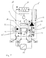
- FIG. 1 shows a schematic representation of the construction of a compact heating system with the structural unit 2 according to the invention, the components of which are delimited by dashed lines in FIG. All arranged inside the dashed boundary components are integrated into the unit.
- the assembly essentially has nine connections for connection to external pipelines or components. These are the connections CHF and CHR for the space heating circuit, the connection DCW for the supply of cold service water and the connection DHW for the heated service water.
- the unit has ports 4 and 6 for connection of the primary heat exchanger 8 in the heating boiler. In the primary heat exchanger 8, the water is heated in the primary circuit via a burner 10, preferably a gas burner.
- a connection 12 for a compensating vessel and two connections 14 and 16 for connecting a water reservoir 18 for storing heated water in the primary circuit are provided on the structural unit 2.
- a pump 20, a 2/3-way valve 22 and a secondary heat exchanger 24 are arranged in a known manner as essential components.
- the fluid or water which is pumped by the pump 20, flows from the pump 20 through the connection 6 to the primary heat exchanger and via the connection 4 back into the assembly 2.
- the 2/3-way valve which can switch the primary circuit between the secondary heat exchanger 24 and the connection CHF for space heating.
- the 2/3-way valve 22 is switched to space heating, the water flows through the connection CHF through the radiator in the rooms to be heated back to the connection CHR to the unit 2 and back to the suction side of the pump 20.
- the water flows in the primary circuit of the 2/3-way valve through the preferably designed as a plate heat exchanger secondary heat exchanger 24 and from there via the terminal 16 through the water tank 18 and the port At the same time, the service water to be heated is passed through the secondary heat exchanger 24 via the connections DHW and DCW and heated there via the primary circuit.
- the water reservoir 18 which is formed as an insulated tank, a certain amount of the heated fluid or water of the primary circuit is cached to allow a faster hot water heating.
- the 2/3-way valve is switched to domestic water heating at intervals of operation of the compact heating system, even if no hot water is taken from us.
- heated water is supplied to the water reservoir 18 by the primary heat exchanger 8 and stored there. This process can be started, for example, via a temperature sensor provided in the water reservoir 18. If now hot water is removed, this is detected by a flow sensor 26.
- the pump 20 is put into operation together with the switching of the 2/3-way valve 22 to hot water, so that stored in the water tank 18 warm heating water from the pump 20 through the primary heat exchanger. 8 and the 2/3-way valve 22 is supplied to the secondary heat exchanger 24.
- domestic water can already be heated in the secondary heat exchanger 24 before the boiler with the burner 10 reaches its operating temperature for heating the primary circuit via the primary heat exchanger 8.
- the water tank 18 shown in the present example is not absolutely necessary, but the terminals 14 and 16 could also be short-circuited or non-existent, that is, the output side of the secondary heat exchanger 24 may be connected directly to the suction side of the pump 20.
- the other components of the assembly 2 correspond to the arrangements of known units for compact heating systems, which is why a more detailed explanation is omitted here.
- space heating circuit which is indicated in Fig. 1 only by a heat exchanger or radiator 27 with associated valve, preferably thermostatic valve, corresponds to conventional arrangements of heating circuits with one or more heat exchangers or radiators.
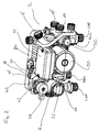
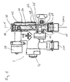
- FIG. 2 shows an overall perspective view of the assembly according to the invention.
- the pump 20 is arranged centrally.
- the 2/3-way valve 22 is arranged, which is actuated via a servomotor 28.
- a line section is formed with a receptacle 30 for a dirt separator.
- the connections CHF, CHR, DHW and DCW are designed to connect the heating circuit or the hot water pipes to the compact heating system.
- a terminal box 32 for connection of the pump and for receiving electronic components is arranged.
- the secondary heat exchanger 24 is mounted in the form of a plate heat exchanger.
- the connection 4 and on the pressure side of the pump 20, the connection 6 for connection to the primary heat exchanger 8 (not shown here) is formed.
- the assembly includes all line sections or components of the fluid circuits between the externally connected primary heat exchanger 8 and the connections CHF, CHR, DHW and DCW for the space heating circuit and the service water supply.
- the ports 14 and 16 for a water reservoir for storing heated water of the primary circuit are arranged in the receiving housing 30 for the dirt separator.
- the terminals 14 and 16 are formed as a threaded connection piece integral with the terminal housing 30.
- the entire assembly 2 is integrally formed as an injection molded part.
- the assembly may be composed of individual housing components.
- the housing part with the receiving housing 30, the housing part for receiving the pump 20 and the housing part for receiving the 2/3-way valve are manufactured as separate components by injection molding and then assembled to the unit 2.
- connection DHW for heated service water is in connection with a line section or channel 34, which extends from the bottom of the assembly, starting from the connection DHW vertically up to the top of the unit 2.
- the upper end side of the channel 34 has at its upper end facing away from the terminal DHW an opening 36 which is closed by a closure element 38.
- Below the opening 36 branches off substantially at right angles from the channel 34 from a connecting channel 40, which establishes the connection of the channel 34 to a port 42 of the secondary heat exchanger 24.
- the heated service water exits the secondary heat exchanger 24 and into the connecting channel 40 a.
- a measuring probe 44 of the flow sensor 26 is inserted into the channel 34.
- the measuring probe 44 is a combined pressure / temperature sensor, which can determine both a pressure or pressure differences and the temperature in the brewing water flowing through the channel 34.
- the detection of the temperature of the heated service water is needed to control the hot water heating, in particular for controlling the burner 10 in the process water heating.
- the pressure sensor of the measuring probe 44 forms part of the flow sensor 26, which detects a flow in the channel 34. When a flow is detected in the channel 34, it means that a faucet for the extraction of heated service water is opened, so that there is a request for heated water.
- the control unit of the compact heating system turns on the burner 10 and the pump 20 and the 2/3-way valve 22 on domestic water heating. Even if a measuring probe 44 is used as a combined temperature and pressure sensor in the present case, the temperature sensor is not absolutely necessary. Thus, the temperature sensor can also be designed as a separate sensor and arranged at a different location than the measuring probe 44 in the structural unit 2.
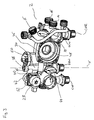
- Fig. 3 shows a view of the assembly 2 according to FIG. 2, wherein the secondary heat exchanger 24, the pump 20 with the terminal box 32 and the 2/3-way valve 22 removed from the assembly 2 and removed from this. Furthermore, the dirt separator is removed from the receiving housing 30.
- the insertion housing 46 is formed for the pump 20 with the suction port 48 of the pump 20. Above the insertion space or housing 46 is connected to the suction port 48, an air separator 50 on the suction side of the pump 20 is arranged. As can be seen in Fig. 3, extends at the back of the unit 2 before the secondary heat exchanger 24 (see Fig. 2) of the channel 34 perpendicular substantially over the entire height of the unit 2.
- the connecting channel 40 can be formed by a further pulling core which can be removed through an opening 52 at the end of the connecting channel 40 facing away from the channel 34.
- the opening 52 is also closed by removal of the pulling core by a closure element.
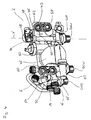
- Fig. 4 shows the assembly of FIG. 2 viewed from the rear side. From the rear, the four ports 42, 54, 56 and 58 can be seen for the secondary heat exchanger 24.
- the connection 54 is also essentially perpendicular through the unit 2 extending channel connected to the DCW connection for cold service water. In this way, the service water to be heated from the port DCW via the channel 60 and the port 54 in the secondary heat exchanger 24 (not shown in Fig. 4) is initiated.
- the heated service water exits the secondary heat exchanger at the port 42 and flows from there inside the unit 2 through the connecting channel 40 and the channel 34 to the DHW, to which the dwelling or house-side hot water pipe is connected to the compact heating system.
- connection 58 the water of the heating circuit is passed from the 2/3-way valve 22 in the secondary heat exchanger 24 for heating the service water.
- the water of the heating circuit exits the secondary heat exchanger at the connection 56 and flows from there inside the assembly 2 into the receiving housing 30 and from there via the channel 62 into the insertion housing 46 to the suction mouth 48 of the pump 20th
- the flow sensor 26 is arranged consisting of a flow resistance or an obstruction 62 and the measuring probe 44.
- the obstruction 62 is made in one piece with the channel 34 or the assembly 2 by injection molding.
- the obstruction extends rod-shaped diametrically through the channel 34 and has, for example, a triangular cross-section.
- the exact structure of the flow sensor consisting of obstruction 62 and measuring probe 44 and in particular the geometric dimensions and the arrangement of measuring probe 44 and obstruction 62 are known from EP 02 028 959.1.
- the measuring probe 44 protrudes into the flow channel 34, so that your pressure transducer 64 is arranged substantially centrally in the channel 34.
- the measuring probe 44 preferably has pressure sensors on two opposite sides in order to be able to detect pressure differences in the interior of the channel 34.
- the measuring probe 44 with the Pressure sensor 64 is arranged in the flow direction S behind the obstruction 62. Due to the flow in the channel 34, in the flow direction S behind the obstruction 62, vortices which are detected by the measuring probe 44 are produced.
- the measuring probe 44 detects pressures or, in particular, their change frequencies via the pressure transducer 64, from which, with known dimensions, the flow velocity in the interior of the channel 34 can be concluded.
- the corresponding metrological evaluation is carried out by an evaluation electronics connected to the measuring probe 44, which can be arranged, for example, in the terminal box 32.
- the measuring probe 44 is inserted through an opening 66 from the front into the channel 34.
- the described straight configuration of the channel 34 wherein the channel 34 extends substantially from the top to the bottom of the assembly 2 over its entire height, has the advantage that the channel 34 can be formed as long as possible, so before the obstruction 62 a as long as possible calming section is created in which the flow can calm down or stabilize before it reaches the flow sensor 26 formed from obstruction 62 and measuring probe 44.
- the straight and smooth configuration of the channel 34 with the openings 36 and 68 formed at its opposite ends allows for easy manufacture of the channel 34 with the obstruction 62 integrally formed therein.
- the opening 36 is closed in later operation by a closure element 38.
- openings can be used for the drawing cores, which must be provided for operation anyway in the assembly 2, so that the number of openings to be closed after the injection molding is minimized.
- the opening 36 for connecting other components such as a filling line or a filling valve for filling the heating circuit with water could be arranged.
- channel 34 is straight from port 36 to port DHW, channel 34 could also be angled or curved.
- the channel 34 may be formed according to the invention by drawing cores, it is only necessary that no undercuts are formed in the channel 34 between the obstruction 62 and the openings 36 and 68, so that after injection molding the drawing cores are pulled out of the openings 36 and 68 can.
- the channel in an angled configuration, could be rectilinear from the obstruction 62 to the opening 38 and the opening 68, respectively, with the conduit portion between the obstruction 62 and the opening 36 being angled to the conduit portion between the obstruction 62 and the opening 68.
- curved drawing cores which can be pulled out along apertures 38 and 68 along correspondingly curved paths, could be used.
- the openings 66 and the connecting channel 40, which communicate with the channel 34, can be formed by further drawing cores.
Landscapes
- Engineering & Computer Science (AREA)
- Physics & Mathematics (AREA)
- Combustion & Propulsion (AREA)
- Thermal Sciences (AREA)
- Chemical & Material Sciences (AREA)
- General Physics & Mathematics (AREA)
- Fluid Mechanics (AREA)
- Mechanical Engineering (AREA)
- General Engineering & Computer Science (AREA)
- Steam Or Hot-Water Central Heating Systems (AREA)
- Instantaneous Water Boilers, Portable Hot-Water Supply Apparatuses, And Control Of Portable Hot-Water Supply Apparatuses (AREA)
- Basic Packing Technique (AREA)
- Yarns And Mechanical Finishing Of Yarns Or Ropes (AREA)
- Resistance Heating (AREA)
Description
- Die Erfindung betrifft eine Baueinheit für eine Kompaktheizungsanlage, insbesondere für eine Gastherme.
- Derartige Kompaktheizungsanlagen, insbesondere Gasthermen, dienen zur Erwärmung von Heizungswasser für die Raumheizung und zur Erwärmung von Brauchwasser. Dabei ist eine Vielzahl von Einzelkomponenten in einem gemeinsamen kompakten Gehäuse vereint. Während bei älteren Konstruktionen die Einzelelemente über Rohre miteinander verbunden wurden, was relativ aufwändig war, geht man seit geraumer Zeit vermehrt dazu über, den gesamten Verrohrungskomplex mit den erforderlichen Armaturen einschließlich Aufnahmen für einzelne Aggregate wie Pumpe, Ventile und dergleichen als Baueinheit auszuführen, welche üblicherweise aus einem oder mehreren Spritzgussteilen aus Kunststoff gefertigt sind. Eine solche Baueinheit bildet einen integrierten Wasserkreislauf, welcher insbesondere die Anschlüsse für den Raumheizungskreislauf sowie für die Brauchwasserzu- und -abfuhr, die erforderlichen Ventile sowie eine Umwälzpumpe enthält. Eine solche Baueinheit ist beispielsweise aus EP 1 130 341 A2 bekannt.
- Für die Brauchwassererwärmung ist ein Strömungssensor erforderlich, welcher über die Strömung im Brauchwasserkreislauf bzw. der Brauchwasserleitung erfasst, ob Brauchwasser angefordert wird, um dann den Brenner und die Umwälzpumpe zur Erwärmung des Brauchwassers aktivieren zu können. Ein solcher Strömungssensor ist beispielsweise aus JP 54-161968 oder US 4,718,283 bekannt. Ein solcher Strömungssensor muss über Flanschverbindungen mit den Brauchwasserleitungen in der Kompaktheizungsanlage verbunden werden, wodurch sich die Zahl der Einzelteile und Montageschritte bei der Montage der Kompaktheizungsanlage erhöht.
- Es ist daher Aufgabe der Erfindung, eine Baueinheit für eine Kompaktheizungsanlage, insbesondere für eine Gastherme zu schaffen, welche eine kostengünstige Anordnung eines Strömungssensors in der Brauchwasserleitung bzw. dem Brauchwasserkreislauf der Kompaktheizungsanlage ermöglicht.
- Diese Aufgabe wird durch eine Baueinheit für eine Kompaktheizungsanlage mit den im Anspruch 1 angegebenen Merkmalen gelöst. Bevorzugte Ausführungsformen ergeben sich aus den Unteransprüchen.
- Die erfindungsgemäße Baueinheit für eine Kompaktheizungsanlage, insbesondere für eine Gastherme, weist zumindest eine Leitung für zu erwärmendes Brauchwasser auf. Vorzugsweise ist direkt an der Baueinheit ein Wärmetauscher, beispielsweise ein Plattenwärmetauscher, angebracht, in welchem das Brauchwasser über den Heizungskreislauf erwärmt wird. Dazu wird das kalte Brauchwasser über eine entsprechende Leitung in der Baueinheit dem Wärmetauscher zu- und über eine weitere Leitung in der Baueinheit von dem Plattenwärmetauscher abgeführt. Dementsprechend sind an der Baueinheit vorzugsweise Anschlüsse für den Brauchwasserein- und Brauchwasserausgang vorhanden, um die Kompaktheizungsanlage mit entsprechenden Kalt- und Warmwasserleitungen der Hausinstallation zu verbinden. Die Brauchwasserleitung im Inneren der Baueinheit weist zumindest einen Leitungsabschnitt auf, in welchem ein Strömungssensor mit einer Obstruktion und einer Messsonde angeordnet ist. Ein solcher Strömungssensor wirkt in der Weise, dass durch die Obstruktion in der Leitung Wirbel in der Strömung erzeugt werden, welche mit Hilfe der Messsonde ausgemessen werden. Die Messsonde erfasst in dem von der Obstruktion erzeugten Wirbel Druckunterschiede bzw. Druckfrequenzen, aus denen bei bekannter Größe der Obstruktion die Strömungsgeschwindigkeit bestimmt werden kann. Ein solcher Sensoraufbau ist beispielsweise aus EP 02 028 959 bekannt. In dem Leitungsabschnitt ist zur Anordnung der Messsonde eine Aufnahme bzw. Öffnung ausgebildet. Die Obstruktion ist im Inneren des Leitungsabschnittes vorzugsweise einstückig mit diesem im Spritzgussverfahren ausgebildet. Um die Obstruktion auf einfache Weise im Inneren des Leitungsabschnittes ausbilden zu können, ist an zwei einander entgegengesetzten Enden des Leitungsabschnittes erfindungsgemäß jeweils eine Öffnung vorgesehen, sodass der Leitungsabschnitt mittels zweier Ziehkerne ausbildbar ist. Ferner ist der Leitungsabschnitt daher vorzugsweise jeweils zumindest zwischen den Öffnungen und der Obstruktion in seiner Längsrichtung ohne Hinterschneidungen ausgebildet. Die Ziehkerne können nach dem Spritzgießen der Baueinheit mit dem Leitungsabschnitt durch die Öffnungen herausgezogen werden. In dem Leitungsabschnitt zwischen Öffnungen und Obstruktion sind bevorzugt keine Hinterschneidungen bzw. Stufen oder Vorsprünge vorhanden, welche ein Entnehmen der Kerne verhindern oder weitere Kerne erfordern würden. Auf diese Weise kann die Obstruktion beim Spritzgießen der Baueinheit aus Kunststoff einstückig in dem Leitungsabschnitt für die Brauchwasserversorgung ausgebildet werden, ohne dass teure Schmelzkerne erforderlich wären. So können die Fertigung der Baueinheit vereinfacht und die Herstellungskosten für die Baueinheit und somit der Kompaktheizungsanlage verringert werden.
- Vorzugsweise verläuft der Leitungsabschnitt zumindest zwischen einer der Öffnungen und der Obstruktion gerade. So kann der Ziehkern zur Ausbildung dieses Leitungsabschnittes in einer linearen Bewegung in Längsrichtung des geraden Leitungsabschnittes durch die Öffnung herausgezogen werden. Der gerade Verlauf des Leitungsabschnittes ermöglicht ferner eine optimale Anströmung der Obstruktion, um eine sichere Funktion des Strömungssensors zur Erfassung des Brauchwasserbedarfes sicherzustellen.
- Dazu verläuft weiter bevorzugt der gesamte Leitungsabschnitt zwischen den beiden einander entgegengesetzten Öffnungen gerade. Dies begünstigt den Strömungsverlauf in dem Leitungsabschnitt und somit die Erfassung der Strömung durch den in dem Leitungsabschnitt angeordneten Strömungssensor. Darüber hinaus kann die Obstruktion sehr einfach durch zwei in Längsrichtung des Leitungsabschnittes linear bewegliche Ziehkerne ausgebildet werden. Dies begünstigt insbesondere die Ausbildung einer bezüglich der Längsachse des Leitungsabschnittes symmetrischen Obstruktion.
- Gemäß einer weiteren bevorzugten Ausführungsform dient eine der Öffnungen in dem Leitungsabschnitt gleichzeitig als Anschluss für eine Brauchwasserleitung, vorzugsweise für das erwärmte Brauchwasser. Auf diese Weise wird die Zahl der erforderlichen Öffnungen in der Baueinheit reduziert. Insbesondere wird die Zahl der Öffnungen, welche lediglich zur Fertigung, nicht jedoch im späteren Betrieb der Baueinheit benötigt werden, reduziert. So muss die eine Öffnung, welche zur Ausbildung der Obstruktion im Inneren des Leitungsabschnittes mittels eines Ziehkernes benötigt wird, nicht nachträglich verschlossen werden, da sie dann später als Brauchwasseranschluss dient. Somit erfüllt die Öffnung in diesem Leitungsabschnitt zwei Funktionen.
- Weiter bevorzugt ist eine der Öffnungen verschlossen ausgebildet. Falls eine oder beide der Öffnungen zur Ausbildung der Obstruktion im späteren Betrieb nicht benötigt werden, können diese durch entsprechende Stopfen oder Verschlüsse geschlossen werden. Vorzugsweise wird jedoch zumindest eine der Öffnungen zur Verbindung des Leitungsabschnittes mit externen Leitungen verwendet, sodass lediglich eine der Öffnungen verschlossen werden muss.
- Gemäß einer besonderen Ausführungsform kann eine der Öffnungen als Anschluss zum Befüllen eines Heizkreislaufes dienen. Das heißt an die Öffnung ist eine Leitung angeschlossen bzw. anschließbar, welche mit dem Heizkreislauf verbunden ist. In dieser Leitung ist zusätzlich zumindest ein Ventil vorgesehen, um die Leitung gezielt öffnen zu können, um Brauchwasser aus dem Leitungsabschnitt des Brauchwasserkreislaufes in den Heizkreislauf für die Raumheizung einzuleiten, um den Raumheizungskreislauf mit Wasser zu befüllen. Die Leitung zwischen dem Brauchwasserkreislauf und dem Heizungskreislauf kann fest oder abnehmbar ausgebildet sein. Wenn die Leitung fest ausgebildet ist, ist sie vorzugsweise ebenfalls in die Baueinheit integriert. Dadurch, dass die eine Öffnung für den Ziehkern zur Ausbildung der Obstruktion im Inneren des Leitungsabschnittes im Betrieb als Anschluss zum Befüllen eines Heizkreislaufes verwendet wird, ist es nicht erforderlich, diese Öffnung zu verschließen. Vielmehr wird mit der Öffnung eine Befüllleitung oder ein Ventil verbunden. Besonders bevorzugt wird eine der beiden Öffnungen an den entgegengesetzten Enden des Leitungsabschnittes Anschluss zum Befüllen des Heizkreislaufes und die andere Öffnung als Anschluss für eine Brauchwasserleitung verwendet. Diese Ausgestaltung hat den Vorteil, dass keine zusätzliche, das heißt im Betrieb nicht benötigte Öffnung, für die Ziehkerne zur Ausbildung des Leitungsabschnittes und der Obstruktion in der Baueinheit vorgesehen werden muss.
- Weiter bevorzugt ist in Einbaulage der Baueinheit die erste der Öffnungen zu einer Unterseite und die zweite der Öffnungen zu einer Oberseite der Baueinheit gerichtet. Die Einbaulage der Baueinheit entspricht der Lage der Baueinheit im montierten Zustand der Kompaktheizungsanlage. Die Baueinheit ist dabei üblicherweise so angeordnet, dass ein an der Baueinheit angebrachter Wärmetauscher, insbesondere Plattenwärmetauscher horizontal angeordnet ist. Die Anordnung der Öffnungen an Ober- und Unterseite der Baueinheit ermöglicht, dass beim Spritzguss die Ziehkerne von zwei entgegengesetzten Seiten vorzugsweise entlang derselben Achse in entgegengesetzten Richtungen zugeführt und aus der fertig gegossenen Baueinheit entnommen werden können. Auf die Weise kann ein langer und vorzugsweise gerader Kanal gebildet werden, welcher sich durch die gesamte Baueinheit hindurch erstreckt. Diese Ausgestaltung hat den Vorteil, dass der Leitungsabschnitt, in dem die Obstruktion ausgebildet ist, möglichst lang ausgebildet werden kann, um für die Strömung eine ausreichend lange Beruhigungsstrecke zu haben, und mittels der Obstruktion gezielte Wirbel für den Strömungssensor in der Strömung erzeugen zu können. Der Leitungsabschnitt, welcher sich zwischen den Öffnungen erstreckt, erstreckt sich vorzugsweise über die gesamte Breite bzw. Höhe der Baueinheit, sodass bei vorgegebenen Außenabmessungen der Baueinheit der vorhandene Bauraum optimal ausgenutzt wird, um einen möglichst langen Leitungsabschnitt zur Aufnahme des Strömungssensors zu schaffen.
- Besonders bevorzugt verläuft der Leitungsabschnitt in Einbaulage der Baueinheit in senkrechter Richtung. So kann die gesamte Bauhöhe der Baueinheit für den Leitungsabschnitt und eine möglichst lange Beruhigungsstrecke ausgenutzt werden. Ferner sind die Öffnungen vorzugsweise an Ober- und Unterseite der Baueinheit frei zugänglich, sodass sie entweder leicht verschlossen oder mit den gewünschten Anbauteilen und/oder externen Leitungen verbunden werden können.
- Vorzugsweise ist eine der Öffnungen an der Unterseite der Baueinheit angeordnet und dient als Anschluss für eine Brauchwasserleitung. Bevorzugt sind alle Anschlüsse der Kompaktheizungsanlage in einer Ebene an der Unterseite der Baueinheit angeordnet. Dies sind die Anschlüsse für die Brauchwasserzufuhr und das erwärmte Brauchwasser sowie die zwei Anschlüsse für den Raumheizungskreislauf. Der Leitungsabschnitt mit dem Strömungssensor erstreckt sich somit vorzugsweise von der Oberseite der Baueinheit zum unteren Ende der Baueinheit und dient der Ableitung von erwärmte Brauchwasser vom Wärmetauscher, in welchem das Brauchwasser erwärmt wird, zu dem Warmwasseranschluss an der Unterseite der Baueinheit. Der in diesem Leitungsabschnitt angeordnete Strömungssensor erfasst die Brauchwasserströmung und gegebenenfalls deren Geschwindigkeit, wenn Brauchwasser durch Öffnen eines Wasserhahns an einer mit der Baueinheit verbundenen Leitung angefordert wird.
- Der Leitungsabschnitt weist weiter bevorzugt in der Nähe einer der beiden Öffnungen, vorzugsweise in der Nähe der oberen Öffnung, einen Anschluss zur Verbindung mit einem Wärmetauscher auf. Der Anschluss zur Verbindung mit einem Wärmetauscher ist als Öffnung oder als weiterer in die Baueinheit integrierter Leitungsabschnitt ausgebildet, welcher die Verbindung zu einem an die Baueinheit angesetzten Wärmetauscher herstellt. Diese Anschlussöffnung ist vorzugsweise in der Nähe der oberen Öffnung des beschriebenen Leitungsabschnittes angeordnet. So erstreckt sich der Leitungsabschnitt mit dem Strömungssensor und der in dem Leitungsabschnitt ausgebildeten Obstruktion von der Unterseite der Baueinheit, an welcher der Leitungsabschnitt mit einer Brauchwasserleitung verbunden ist zur Oberseite der Baueinheit, an der der Wärmetauscher bzw. dessen Brauchwasserausgang angesetzt ist. Vorzugsweise ist der Wärmetauscher rückseitig an die Baueinheit angesetzt, wobei der Ausgang für das zu erwärmende Brauchwasser in der Nähe der Oberseite der Baueinheit gelegen ist. Auf diese Weise wird bei einer möglichst kompakten Baueinheit gleichzeitig ein ausreichend langer und gerader Leitungsabschnitt zur Anordnung des Strömungssensors geschaffen. Alternativ kann auch der Brauchwassereingang des Wärmetauschers oben angeordnet und mit dem Leitungsabschnitt mit dem Strömungssensor verbunden sein. Dann liegt der Strömungssensor im Brauchwasserzulauf anstatt, wie oben beschrieben, im Brauchwasserablauf.
- Nachfolgend wird eine Ausführungsform der Erfindung beispielhaft anhand der beigefügten Figuren beschrieben. In diesen zeigt:
- Fig. 1:
- schematisch den Aufbau einer Kompaktheizungsanlage mit der erfindungsgemäßen Baueinheit,
- Fig. 2:
- eine perspektivische Gesamtansicht der Baueinheit von vorne,
- Fig. 3:
- eine Ansicht entsprechend Fig. 1, jedoch ohne Plattenwärmetauscher und Umwälzpumpe,
- Fig. 4:
- eine perspektivische Ansicht der Baueinheit gemäß Fig. 2 von der Rückseite her gesehen und
- Fig. 5:
- eine Schnittansicht der Baueinheit gemäß Fig. 1 bis 3 entlang der Längsachse X des Leitungsabschnittes mit dem Strömungssensor.
- Figur 1 zeigt in einer schematischen Darstellung den Aufbau einer Kompaktheizungsanlage mit der erfindungsgemäßen Baueinheit 2, deren Komponenten in Figur 1 durch gestrichelte Linien umgrenzt sind. Alle im Inneren der gestrichelten Umgrenzung angeordneten Bauteile sind in die Baueinheit integriert. Die Baueinheit weist im Wesentlichen neun Anschlüsse zur Verbindung mit externen Rohrleitungen bzw. Komponenten auf. Dies sind die Anschlüsse CHF und CHR für den Raumheizungskreislauf, der Anschluss DCW für die Zufuhr von kaltem Brauchwasser und der Anschluss DHW für das erwärmte Brauchwasser. Darüber hinaus weist die Baueinheit Anschlüsse 4 und 6 zum Anschluss des Primärwärmetauschers 8 in dem Heizungskessel auf. In dem Primärwärmetauscher 8 wird über einen Brenner 10, vorzugsweise einen Gasbrenner, das Wasser im Primärkreislauf erhitzt. Ferner sind an der Baueinheit 2 ein Anschluss 12 für ein Ausgleichsgefäß und zwei Anschlüsse 14 und 16 zum Anschluss eines Wasserspeichers 18 zum Speichern von erwärmtem Wasser im Primärkreislauf vorgesehen.
- In der Baueinheit 2 sind in bekannter Weise als wesentliche,Komponenten eine Pumpe 20, ein 2/3-Wege-Ventil 22 sowie ein Sekundärwärmetauscher 24 angeordnet. Im Primärkreislauf strömt das Fluid bzw. Wasser, welches von der Pumpe 20 gefördert wird, von der Pumpe 20 durch den Anschluss 6 zu dem Primärwärmetauscher und über den Anschluss 4 zurück in die Baueinheit 2. Dort erreicht es das 2/3-Wege-Ventil, welches den Primärkreislauf zwischen dem Sekundärwärmetauscher 24 und dem Anschluss CHF für die Raumheizung umschalten kann. Wenn das 2/3-Wege-Ventil 22 auf Raumheizung geschaltet ist, fließt das Wasser über den Anschluss CHF durch die Heizkörper in den zu heizenden Räumen zurück zu dem Anschluss CHR an der Baueinheit 2 und in dieser wieder zur Saugseite der Pumpe 20. Wenn das 2/3-Wege-Ventil 22 zur Brauchwassererwärmung umgeschaltet wird, strömt das Wasser im Primärkreislauf vom 2/3-Wege-Ventil durch den vorzugsweise als Plattenwärmetauscher ausgebildeten Sekundärwärmetauscher 24 und von dort über den Anschluss 16 durch den Wasserspeicher 18 und über den Anschluss 14 zurück in die Baueinheit und in dieser zur Saugseite der Pumpe 20. Gleichzeitig wird über die Anschlüsse DHW und DCW das zu erwärmende Brauchwasser durch den Sekundärwärmetauscher 24 geleitet und dort über den Primärkreislauf erwärmt.
- In dem Wasserspeicher 18, welcher als isolierter Tank ausgebildet ist, wird eine bestimmte Menge des erwärmten Fluids bzw. Wassers des Primärkreislaufes zwischengespeichert, um eine schnellere Brauchwassererwärmung zu ermöglichen. Dazu wird bei Betrieb der Kompaktheizungsanlage in Zeitabständen das 2/3-Wege-Ventil auf Brauchwassererwärmung umgeschaltet, auch wenn kein Brauchwasser entnommen wir. Auf diese Weise wird durch den Primärwärmetauscher 8 erwärmtes Wasser dem Wasserspeicher 18 zugeführt und dort gespeichert. Dieser Vorgang kann beispielsweise über einen in dem Wasserspeicher 18 vorgesehenen Temperatursensor gestartet werden. Wenn nun Brauchwasser entnommen wird, wird dieses über einen Strömungssensor 26 erfasst.
- Dies veranlasst die Steuerung der Heizungsanlage das 2/3-Wege-Ventil auf Brauchwassererwärmung umzuschalten und den Brenner 10 in dem Kessel zu starten, um dass Wasser des Primärkreislaufes zu erwärmen und dann über den Sekundärwärmetauscher 24 wie beschrieben das Brauchwasser zu erwärmen. Gleich nach Erfassung der Brauchwasserentnahme über den Strömungsmesser 26 wird gemeinsam mit dem Umschalten des 2/3-Wege-Ventils 22 auf Brauchwassererwärmung auch die Pumpe 20 in Betrieb gesetzt, sodass das in dem Wasserspeicher 18 gespeicherte warme Heizungswasser von der Pumpe 20 durch den Primärwärmetauscher 8 und das 2/3-Wege-Ventil 22 dem Sekundärwärmetauscher 24 zugeführt wird. So kann in dem Sekundärwärmetauscher 24 bereits Brauchwasser erwärmt werden, bevor der Heizkessel mit dem Brenner 10 seine Betriebstemperatur zum Aufheizen des Primärkreislaufes über den Primärwärmetauscher 8 erreicht.
- Der im vorliegenden Beispiel gezeigte Wasserspeicher 18 ist jedoch nicht unbedingt erforderlich, vielmehr könnten die Anschlüsse 14 und 16 auch kurzgeschlossen oder nicht vorhanden sein, das heißt die Ausgangsseite des Sekundärwärmetauschers 24 direkt mit der Saugseite der Pumpe 20 verbunden sein.
- Die übrigen Bauteile der Baueinheit 2, insbesondere Überdruck- und Füllventile, Bypassleitung, etc. entsprechen den Anordnungen bekannter Baueinheiten für Kompaktheizungsanlagen, weshalb an dieser Stelle auf eine nähere Erläuterung verzichtet wird. Auch der mit den Anschlüssen CHF und CHR verbundene Raumheizungskreislauf, welcher in Fig. 1 lediglich durch einen Wärmetauscher bzw. Heizkörper 27 mit zugehörigem Ventil, vorzugsweise Thermostatventil, angedeutet ist, entspricht üblichen Anordnungen von Heizungskreisläufen mit einem oder mehreren Wärmetauschern bzw. Heizkörpern.
- Die konstruktive Ausgestaltung der erfindungsgemäßen Baueinheit wird beispielhaft anhand der Fig. 2 bis 5 beschrieben. Figur 2 zeigt eine perspektivische Gesamtansicht der erfindungsgemäßen Baueinheit. Zentral angeordnet ist die Pumpe 20. An einer Seite der Pumpe 20, in Figur 2 links, ist das 2/3-Wege-Ventil 22 angeordnet, welches über einen Stellmotor 28 betätigt wird. An der entgegengesetzten Seite der Pumpe 20, das heißt in Figur 2 rechts, ist ein Leitungsabschnitt mit einer Aufnahme 30 für einen Schmutzabscheider ausgebildet. An der Unterseite der Baueinheit 2 sind die Anschlüsse CHF, CHR, DHW und DCW zum Anschluss des Heizungskreislaufs bzw. der Brauchwasserleitungen an die Kompaktheizungsanlage ausgebildet. Zentral oberhalb der Pumpe 20 ist ein Klemmenkasten 32 zum Anschluss der Pumpe und zur Aufnahme von Elektronikkomponenten angeordnet. Rückseitig ist an der Baueinheit 2 der Sekundärwärmetauscher 24 in Form eines Plattenwärmetauschers angebracht. Seitlich am Zwei/Drei-Wege-Ventil 22 ist der Anschluss 4 und an der Druckseite der Pumpe 20 der Anschluss 6 zur Verbindung mit dem Primärwärmetauscher 8 (hier nicht gezeigt) ausgebildet. Wie bereits anhand von Figur 1 erläutert, beinhaltet die Baueinheit alle Leitungsabschnitte bzw. Komponenten der Fluidkreisläufe zwischen dem extern angeschlossenen Primärwärmetauscher 8 sowie den Anschlüssen CHF, CHR, DHW und DCW für den Raumheizungskreislauf und die Brauchwasserversorgung.
- In der Ausführungsform gemäß Figur 2 sind in dem Aufnahmegehäuse 30 für den Schmutzabscheider die Anschlüsse 14 und 16 für einen Wasserspeicher zur Speicherung erwärmten Wassers des Primärkreislaufes angeordnet. Die Anschlüsse 14 und 16 sind als Anschlussstutzen mit Gewinde einstückig mit dem Anschlussgehäuse 30 ausgebildet. Vorzugsweise ist die gesamte Baueinheit 2 einstückig als Spritzgussteil ausgebildet. Alternativ kann die Baueinheit aus einzelnen Gehäusekomponenten zusammengesetzt sein. So können der Gehäuseteil mit dem Aufnahmegehäuse 30, der Gehäuseteil zur Aufnahme der Pumpe 20 sowie der Gehäuseteil zur Aufnahme des 2/3-Wege-Ventils als separate Bauteile im Spritzguss gefertigt werden und anschließend zu der Baueinheit 2 zusammengesetzt werden.
- Der Anschluss DHW für erwärmtes Brauchwasser steht in Verbindung mit einem Leitungsabschnitt bzw. Kanal 34, welcher sich von der Unterseite der Baueinheit ausgehend von dem Anschluss DHW senkrecht nach oben bis zur Oberseite der Baueinheit 2 erstreckt. Die obere Stirnseite des Kanals 34 weist an seinem oberen, dem Anschluss DHW abgewandten Stirnende eine Öffnung 36 auf, welche durch ein Verschlusselement 38 verschlossen ist. Unterhalb der Öffnung 36 zweigt im Wesentlichen rechtwinklig von dem Kanal 34 ein Verbindungskanal 40 ab, welcher die Verbindung des Kanals 34 zu einem Anschluss 42 des Sekundärwärmetauschers 24 herstellt. Am Anschluss 42 tritt das erwärmte Brauchwasser aus dem Sekundärwärmetauscher 24 aus und in den Verbindungskanal 40 ein.
- Von der Vorderseite in Fig. 2, welche auch in Einbaulage der Baueinheit 2 die Vorderseite bildet, ist in den Kanal 34 eine Messsonde 44 des Strömungssensors 26 eingesetzt. Die Messsonde 44 ist ein kombinierter Druck-/Temperaturaufnehmer, welcher sowohl einen Druck bzw. Druckdifferenzen und die Temperatur in dem durch den Kanal 34 strömenden Brauwasser bestimmen kann. Die Erfassung der Temperatur des erwärmten Brauchwassers wird zur Regelung der Brauchwassererwärmung, insbesondere zur Steuerung des Brenners 10 bei der Brauchwassererwärmung benötigt. Der Druckaufnehmer der Messsonde 44 bildet einen Teil des Strömungssensors 26, welcher eine Strömung in dem Kanal 34 erfasst. Wenn eine Strömung in dem Kanal 34 erfasst wird, bedeutet dies, dass ein Wasserhahn zur Entnahme von erwärmtem Brauchwasser geöffnet ist, sodass eine Anforderung nach erwärmtem Wasser besteht. Dann schaltet die Steuerungseinheit der Kompaktheizungsanlage wie beschrieben den Brenner 10 und die Pumpe 20 ein sowie das 2/3-Wege-Ventil 22 auf Brauchwassererwärmung. Auch wenn im vorliegenden Fall eine Messsonde 44 als kombinierter Temperatur- und Drucksensor eingesetzt wird, ist der Temperatursensor nicht unbedingt erforderlich. So kann der Temperatursensor auch als separater Sensor ausgebildet und an anderer Stelle als die Messsonde 44 in der Baueinheit 2 angeordnet sein.
- Fig. 3 zeigt eine Ansicht der Baueinheit 2 entsprechend Fig. 2, wobei der Sekundärwärmetauscher 24, die Pumpe 20 mit dem Klemmenkasten 32 sowie das 2/3-Wege-Ventil 22 aus der Baueinheit 2 entnommen bzw. von dieser abgenommen sind. Ferner ist aus dem Aufnahmegehäuse 30 der Schmutzabscheider entfernt. Zentral in der Baueinheit 2 ist das Einschubgehäuse 46 für die Pumpe 20 mit dem Saugmund 48 der Pumpe 20 ausgebildet. Oberhalb des Einschubraumes bzw. -gehäuses 46 ist mit dem Saugmund 48 verbunden ein Luftabscheider 50 an der Saugseite der Pumpe 20 angeordnet. Wie in Fig. 3 zu erkennen ist, erstreckt sich an der Rückseite der Baueinheit 2 vor dem Sekundärwärmetauscher 24 (siehe Fig. 2) der Kanal 34 senkrecht im Wesentlichen über die gesamte Bauhöhe der Baueinheit 2. Durch die gerade hinterschneidungsfreie Ausgestaltung des Kanals 34 mit dem an seinen entgegengesetzten Enden ausgebildeten Öffnungen DHW und 38, ist es möglich, den Kanal 34 allein durch Ziehkerne ohne den Einsatz von Schmelzkernen auszubilden. Der Verbindungskanal 40 kann durch einen weiteren Ziehkern, welcher durch eine Öffnung 52 an dem dem Kanal 34 abgewandten Ende des Verbindungskanals 40 entnommen werden kann, ausgebildet werden. Die Öffnung 52 wird nach Entnahme des Ziehkerns ebenfalls durch ein Verschlusselement verschlossen.
- Fig. 4 zeigt die Baueinheit gemäß Fig. 2 von der Rückseite her betrachtet. Von der Rückseite her sind die vier Anschlüsse 42, 54, 56 und 58 für den Sekundärwärmetauscher 24 zu erkennen. Der Anschluss 54 ist über einen sich ebenfalls im Wesentlichen senkrecht durch die Baueinheit 2 erstreckenden Kanal mit dem Anschluss DCW für kaltes Brauchwasser verbunden. Auf diese Weise wird das zu erwärmende Brauchwasser von dem Anschluss DCW über den Kanal 60 und den Anschluss 54 in den Sekundärwärmetauscher 24 (in Fig. 4 nicht gezeigt) eingeleitet. Das erwärmte Brauchwasser tritt aus dem Sekundärwärmetauscher an dem Anschluss 42 aus und fließt von dort im Inneren der Baueinheit 2 durch den Verbindungskanal 40 und den Kanal 34 zu dem Anschluss DHW, an welchem die wohnungs- bzw. hausseitige Warmwasserleitung mit der Kompaktheizungsanlage verbunden wird. Durch den Anschluss 58 wird das Wasser des Heizungskreislaufes von dem 2/3-Wege-Ventil 22 in den Sekundärwärmetauscher 24 zur Erwärmung des Brauchwassers geleitet. Das Wasser des Heizungskreislaufes tritt aus dem Sekundärwärmetauscher am Anschluss 56 aus und fließt von dort im Inneren der Baueinheit 2 in das Aufnahmegehäuse 30 und von dort über den Kanal 62 in das Einschubgehäuse 46 zum Saugmund 48 der Pumpe 20.
- Der Aufbau und die Funktion des Kanals 34 wird näher anhand der Schnittansicht in Fig. 5 erläutert, welche einen Schnitt entlang der Längsachse X des Kanals 34 zeigt. Im Inneren des Kanals 34 ist der Strömungssensor 26 bestehend aus einem Strömungswiderstand bzw. einer Obstruktion 62 und der Messsonde 44 angeordnet. Die Obstruktion 62 ist einstückig mit dem Kanal 34 bzw. der Baueinheit 2 im Spritzguss gefertigt. Die Obstruktion erstreckt sich stabförmig diametral durch den Kanal 34 und weist beispielsweise einen dreieckigen Querschnitt auf. Der genaue Aufbau des Strömungssensors bestehend aus Obstruktion 62 und Messsonde 44 und insbesondere die geometrischen Abmessungen und die Anordnung von Messsonde 44 und Obstruktion 62 sind aus EP 02 028 959.1 bekannt. Die Messsonde 44 ragt in den Strömungskanal 34 hinein, sodass Ihr Druckaufnehmer 64 im Wesentlichen zentral in dem Kanal 34 angeordnet ist. Dabei weist die Messsonde 44 vorzugsweise Druckaufnehmer an zwei entgegengesetzten Seiten auf, um Druckdifferenzen im Inneren des Kanals 34 erfassen zu können. Die Messsonde 44 mit dem Druckaufnehmer 64 ist in Strömungsrichtung S hinter der Obstruktion 62 angeordnet. Durch die Strömung in dem Kanal 34 entstehen in Strömungsrichtung S hinter der Obstruktion 62 Wirbel, welche durch die Messsonde 44 messtechnisch erfasst werden. Dabei erfasst die Messsonde 44 über den Druckaufnehmer 64 Drücke bzw. insbesondere deren Änderungsfrequenzen, aus denen bei bekannten Abmessungen auf die Strömungsgeschwindigkeit im Inneren des Kanals 34 geschlossen werden kann. Die entsprechende messtechnische Auswertung erfolgt durch eine an die Messsonde 44 angeschlossene Auswerteelektronik, welche beispielsweise in dem Klemmenkasten 32 angeordnet sein kann.
- Die Messsonde 44 wird durch eine Öffnung 66 von vorne in den Kanal 34 eingesetzt. Die beschriebene gerade Ausgestaltung des Kanals 34, wobei sich der Kanal 34 im Wesentlichen von der Oberseite bis zur Unterseite der Baueinheit 2 über deren gesamte Bauhöhe erstreckt, hat den Vorteil, dass der Kanal 34 möglichst lang ausgebildet werden kann, sodass vor der Obstruktion 62 eine möglichst lange Beruhigungsstrecke geschaffen wird, in welcher sich die Strömung beruhigen bzw. stabilisieren kann, bevor sie den aus Obstruktion 62 und Messsonde 44 gebildeten Strömungssensor 26 erreicht. Die gerade und glatte Ausgestaltung des Kanals 34 mit den an seinen entgegengesetzten Enden ausgebildeten Öffnungen 36 und 68 ermöglicht eine einfache Fertigung des Kanals 34 mit der darin einstückig ausgebildeten Obstruktion 62. So ist es möglich durch die Öffnungen 38 und 68 Ziehkerne in die Form einzusetzen und aus der fertig gegossenen Baueinheit 2 in Richtung der Längsachse X zu entnehmen. Zur Ausbildung der Obstruktion 62 im Inneren des Kanals 34 sind somit keine Schmelzkerne erforderlich. Die Obstruktion 62 wird zwischen den von den entgegengesetzten Öffnungen 36 und 68 in entgegengesetzten Richtungen zugeführten Ziehkernen ausgebildet. Die Öffnung 36 wird im späteren Betrieb durch ein Verschlusselement 38 verschlossen. In die Öffnung 68 wird ein Anschlussstutzen zur Ausbildung des Anschlusse DHW für eine wohnungs- bzw. hausseitige Warmwasserleitung eingesetzt bzw. eingepresst. So können für die Ziehkerne Öffnungen verwendet werden, welche zum Betrieb ohnehin in der Baueinheit 2 vorgesehen werden müssen, sodass die Anzahl der nach dem Spritzgießen zu verschließenden Öffnungen minimiert wird. Zu diesem Zweck könnte auch die Öffnung 36 zum Anschluss weiterer Komponenten, beispielsweise einer Füllleitung bzw. eines Füllventils zum Befüllen des Heizungskreislaufes mit Wasser angeordnet werden.
- Auch wenn im gezeigten Beispiel der Kanal 34 von der Öffnung 36 bis zu dem Anschluss DHW gerade ausgebildet ist, könnte der Kanal 34 auch gewinkelt oder gekrümmt ausgebildet werden. Damit der Kanal 34 erfindungsgemäß durch Ziehkerne ausgebildet werden kann, ist es lediglich erforderlich, dass in dem Kanal 34 zwischen der Obstruktion 62 und den Öffnungen 36 und 68 keinerlei Hinterschneidungen ausgebildet sind, sodass nach dem Spritzgießen die Ziehkerne aus den Öffnungen 36 und 68 herausgezogen werden können. Bei einer gewinkelten Ausgestaltung könnte der Kanal beispielsweise ausgehend von der Obstruktion 62 jeweils zu der Öffnung 38 und der Öffnung 68 geradlinig verlaufen, wobei der Leitungsabschnitt zwischen der Obstruktion 62 und der Öffnung 36 zu dem Leitungsabschnitt zwischen der Obstruktion 62 und der Öffnung 68 abgewinkelt verläuft. Zur Ausbildung eines gekrümmten Kanals 34 könnten gekrümmte Ziehkerne, welche entlang entsprechend gekrümmter Bahnen aus den Öffnungen 38 und 68 herausgezogen werden können, Verwendung finden. Die Öffnungen 66 sowie der Verbindungskanal 40, welche mit dem Kanal 34 in Verbindung stehen, können durch weitere Ziehkerne ausgebildet werden. So kann bei der erfindungsgemäßen Baueinheit auf die Verwendung von Schmelzkernen zur Ausbildung des Kanals 34 mit dem Strömungssensor 26 verzichtet werden.
-
- 2
- Baueinheit
- 4
- Anschluss
- 6
- Anschluss
- 8
- Primärwärmetauscher
- 10
- Brenner
- 12
- Anschluss für Ausgleichsgefäß
- 14
- Anschluss für Wasserspeicher
- 16
- Anschluss für Wasserspeicher
- 18
- Wasserspeicher
- 20
- Pumpe
- 22
- 2/3-Wege-Ventil
- 24
- Sekundärwärmetauscher
- 26
- Strömungssensor
- 27
- Heizkörper
- 28
- Stellmotor
- 30
- Aufnahmegehäuse
- 32
- Klemmenkasten
- 34
- Kanal
- 36
- Öffnung
- 38
- Verschlusselement
- 40
- Verbindungskanal
- 42
- Anschluss
- 44
- Messsonde
- 46
- Einschubgehäuse
- 48
- Saugmund
- 50
- Luftabscheider
- 52
- Öffnung
- 54
- Anschluss für Sekundärwärmetauscher
- 56
- Anschluss für Sekundärwärmetauscher
- 58
- Anschluss für Sekundärwärmetauscher
- 60
- Kanal
- 62
- Obstruktion
- 64
- Druckaufnehmer
- 66
- Öffnung
- 68
- Öffnung
- DCW
- Anschluss für kaltes Brauchwasser
- DHW
- Anschluss für warmes Brauchwasser
- DHF
- Anschluss für Raumheizungs-Vorlauf
- CHR
- Anschluss für Raumheizungs-Rücklauf
- S
- Strömungsrichtung
- X
- Längsachse
Claims (10)
- Baueinheit für eine Kompaktheizungsanlage, insbesondere für eine Gastherme, wobei die Baueinheit (2) als Spritzgussteil aus Kunststoff ausgebildet ist und einen integrierten Wasserkreislauf bildet, welcher die Anschlüsse für den Raumheizungskreislauf (CHF, CHR) sowie für die Brauchwasserzu- und abfuhr (DCW, DHW), ein 2/3-Wege-Ventil (22), einen Sekundärwärmetauscher (24) und eine Umwälzpumpe (20) enthält, und wobei in der Baueinheit (2) zumindest eine Leitung für zu erwärmendes Brauchwasser angeordnet ist, welche zumindest einen Leitungsabschnitt (34) aufweist, in welchem ein Strömungssensor (26) angeordnet ist, dadurch gekennzeichnet, dass der Strömungssensor eine Obstruktion (62) und eine Messsonde (44) aufweist und dass an zwei einander entgegengesetzten Enden des Leitungsabschnittes (34) jeweils eine Öffnung (36, 68) vorgesehen ist und der Leitungsabschnitt zumindest zwischen den Öffnungen (36, 68) und der Obstruktion derart ausgebildet ist, dass er mittels zweier Ziehkerne ausbildbar ist.
- Baueinheit nach Anspruch 1, dadurch gekennzeichnet, dass der Leitungsabschnitt (34) zumindest zwischen einer der Öffnungen (36, 68) und der Obstruktion (62) gerade verläuft.
- Baueinheit nach Anspruch 1 oder 2, dadurch gekennzeichnet, dass der Leitungsabschnitt (34) zwischen den beiden einander entgegengesetzten Öffnungen (36, 68) gerade verläuft.
- Baueinheit nach einem der vorangehenden Ansprüche, dadurch gekennzeichnet, dass eine der Öffnungen (68) gleichzeitig als Anschluss (DHW) für eine Brauchwasserleitung, vorzugsweise für das erwärmte Brauchwasser dient.
- Baueinheit nach einem der vorangehenden Ansprüche, dadurch gekennzeichnet, dass eine der Öffnungen (36) verschlossen ist.
- Baueinheit nach einem der vorangehenden Ansprüche, dadurch gekennzeichnet, dass eine der Öffnungen (36) als Anschluss zum Befüllen eines Heizkreislaufes dienen kann.
- Baueinheit nach einem der vorangehenden Ansprüche, dadurch gekennzeichnet, dass in Einbaulage der Baueinheit (2) die erste der Öffnungen (68) zu einer Unterseite und die zweite der Öffnungen (36) zu einer Oberseite der Baueinheit (2) hin gerichtet ist.
- Baueinheit nach einem der vorangehenden Ansprüche, dadurch gekennzeichnet, dass der Leitungsabschnitt (34) sich in Einbaulage der Baueinheit (2) in senkrechter Richtung (X) erstreckt.
- Baueinheit nach einem der vorangehenden Ansprüche, dadurch gekennzeichnet, dass eine der Öffnungen (68) an der Unterseite der Baueinheit (2) angeordnet ist und als Anschluss (DHW) für eine Brauchwasserleitung dienen kann,
- Baueinheit nach einem der vorangehenden Ansprüche, dadurch gekennzeichnet, dass der Leitungsabschnitt (34) in der Nähe einer der beiden Öffnungen (36, 68), vorzugsweise in der Nähe der oberen Öffnung (36), einen Anschluss (42) zur Verbindung mit einem Wärmetauscher (24) aufweist.
Priority Applications (3)
| Application Number | Priority Date | Filing Date | Title |
|---|---|---|---|
| AT03025082T ATE356974T1 (de) | 2003-11-03 | 2003-11-03 | Baueinheit für eine kompaktheizungsanlage |
| EP03025082A EP1528371B1 (de) | 2003-11-03 | 2003-11-03 | Baueinheit für eine Kompaktheizungsanlage |
| DE50306804T DE50306804D1 (de) | 2003-11-03 | 2003-11-03 | Baueinheit für eine Kompaktheizungsanlage |
Applications Claiming Priority (1)
| Application Number | Priority Date | Filing Date | Title |
|---|---|---|---|
| EP03025082A EP1528371B1 (de) | 2003-11-03 | 2003-11-03 | Baueinheit für eine Kompaktheizungsanlage |
Publications (2)
| Publication Number | Publication Date |
|---|---|
| EP1528371A1 EP1528371A1 (de) | 2005-05-04 |
| EP1528371B1 true EP1528371B1 (de) | 2007-03-14 |
Family
ID=34400510
Family Applications (1)
| Application Number | Title | Priority Date | Filing Date |
|---|---|---|---|
| EP03025082A Expired - Lifetime EP1528371B1 (de) | 2003-11-03 | 2003-11-03 | Baueinheit für eine Kompaktheizungsanlage |
Country Status (3)
| Country | Link |
|---|---|
| EP (1) | EP1528371B1 (de) |
| AT (1) | ATE356974T1 (de) |
| DE (1) | DE50306804D1 (de) |
Families Citing this family (4)
| Publication number | Priority date | Publication date | Assignee | Title |
|---|---|---|---|---|
| ITPD20090018A1 (it) * | 2009-01-29 | 2010-07-30 | Italtecnica S R L | Dispositivo di raccordo particolarmente per gruppi autoclave ad elettropompa |
| DE102009038745A1 (de) * | 2009-08-27 | 2011-03-03 | Wilo Se | Baueinheit für einen Fluidkreislauf |
| EP2489951B1 (de) * | 2011-02-21 | 2017-04-05 | Gerdes OHG | Elektrischer Durchlauferhitzer |
| PL2613097T5 (pl) | 2012-01-09 | 2021-06-14 | Grundfos Holding A/S | Przyrząd grzejny |
Family Cites Families (7)
| Publication number | Priority date | Publication date | Assignee | Title |
|---|---|---|---|---|
| JPS54161968A (en) * | 1978-06-12 | 1979-12-22 | Yokogawa Hokushin Electric Corp | Production of flow velocity and flow rate measuring device |
| US4718283A (en) * | 1987-01-30 | 1988-01-12 | Itt Corporation | Vortex meter body |
| GB2250334B (en) * | 1990-11-21 | 1994-09-07 | Imi Range Ltd | Waterheating apparatus |
| DE19636360C2 (de) * | 1996-09-06 | 2001-05-23 | Bosch Gmbh Robert | Verfahren zur Brauchwasserbereitstellung in einem kombinierten System |
| ES2133006T3 (es) * | 1996-11-08 | 1999-08-16 | Flowtec Ag | Detector de circulacion turbulenta. |
| IT1308197B1 (it) * | 1999-02-24 | 2001-12-10 | Fontecal S P A | Gruppo idraulico componibile. |
| DE10007924A1 (de) * | 2000-02-21 | 2001-08-23 | Wilo Gmbh | Anschlußvorrichtung für eine Heizungspumpe |
-
2003
- 2003-11-03 AT AT03025082T patent/ATE356974T1/de not_active IP Right Cessation
- 2003-11-03 DE DE50306804T patent/DE50306804D1/de not_active Expired - Lifetime
- 2003-11-03 EP EP03025082A patent/EP1528371B1/de not_active Expired - Lifetime
Also Published As
| Publication number | Publication date |
|---|---|
| ATE356974T1 (de) | 2007-04-15 |
| DE50306804D1 (de) | 2007-04-26 |
| EP1528371A1 (de) | 2005-05-04 |
Similar Documents
| Publication | Publication Date | Title |
|---|---|---|
| EP2397777B1 (de) | Gehäuseeinheit für eine Heizungsanlage | |
| EP2312224B1 (de) | Wärmepumpe mit einem Hydraulikmodul | |
| EP1967714B1 (de) | Kühlmittelregler und Verfahren zu dessen Herstellung | |
| EP2613097B1 (de) | Heizgerät | |
| EP1528330B1 (de) | Baueinheit für eine Kompaktheizungsanlage | |
| EP0920596A1 (de) | Monolithischer wärmespeicherschrank | |
| EP1528329B1 (de) | Baueinheit für eine Kompaktheizungsanlage | |
| EP2428748B1 (de) | Plattenheizkörper und Verfahren zum Leiten eines Heizmittels | |
| EP1528371B1 (de) | Baueinheit für eine Kompaktheizungsanlage | |
| DE102007019389B4 (de) | Formwerkzeugtemperiersystem, Vorrichtung mit Formwerkzeugtemperiersystem und Verfahren zum Temperieren einer Vorrichtung sowie zur Herstellung der Vorrichtung | |
| EP1418387B1 (de) | Kompaktheizungsanlage mit zwei Heizkreisen | |
| EP1884720B1 (de) | Baueinheit für eine Kompaktheizungsanlage | |
| EP1939539B1 (de) | Vorrichtung zum Speisen von Hoch- und Niedrigenergieverbrauchskreisen | |
| EP2093517B1 (de) | Baueinheit für eine Kompaktheizungsanlage | |
| EP2093515B1 (de) | Teilbaueinheit für eine Kompaktheizungsanlage | |
| WO1993019332A1 (de) | Elektrischer durchlauferhitzer | |
| EP2827077B1 (de) | Warmwasserspeicher | |
| EP1884723B1 (de) | Baueinheit | |
| EP1528328B1 (de) | Baueinheit für eine Kompaktheizungsanlage | |
| EP1884717B1 (de) | Heizungsanlage | |
| DE102005058570B3 (de) | Verfahren zur Warmwasserbereitung mit einem Wärmeerzeuger und einem Schichtladespeicher | |
| EP4242531B1 (de) | Frostschutzvorrichtung für wasserversorgungsvorrichtung in freizeitfahrzeugen | |
| DE102007042232A1 (de) | Wärmetauscher und Verfahren zum Herstellen und Betreiben | |
| DE10014454A1 (de) | Anschlusseinrichtung für einen Heizkörper | |
| DE29715784U1 (de) | Ventilgruppe für Fußbodenheizungen |
Legal Events
| Date | Code | Title | Description |
|---|---|---|---|
| PUAI | Public reference made under article 153(3) epc to a published international application that has entered the european phase |
Free format text: ORIGINAL CODE: 0009012 |
|
| 17P | Request for examination filed |
Effective date: 20041023 |
|
| AK | Designated contracting states |
Kind code of ref document: A1 Designated state(s): AT BE BG CH CY CZ DE DK EE ES FI FR GB GR HU IE IT LI LU MC NL PT RO SE SI SK TR |
|
| AX | Request for extension of the european patent |
Extension state: AL LT LV MK |
|
| AKX | Designation fees paid |
Designated state(s): AT BE BG CH CY CZ DE DK EE ES FI FR GB GR HU IE IT LI LU MC NL PT RO SE SI SK TR |
|
| GRAP | Despatch of communication of intention to grant a patent |
Free format text: ORIGINAL CODE: EPIDOSNIGR1 |
|
| GRAS | Grant fee paid |
Free format text: ORIGINAL CODE: EPIDOSNIGR3 |
|
| GRAA | (expected) grant |
Free format text: ORIGINAL CODE: 0009210 |
|
| AK | Designated contracting states |
Kind code of ref document: B1 Designated state(s): AT BE BG CH CY CZ DE DK EE ES FI FR GB GR HU IE IT LI LU MC NL PT RO SE SI SK TR |
|
| PG25 | Lapsed in a contracting state [announced via postgrant information from national office to epo] |
Ref country code: FI Free format text: LAPSE BECAUSE OF FAILURE TO SUBMIT A TRANSLATION OF THE DESCRIPTION OR TO PAY THE FEE WITHIN THE PRESCRIBED TIME-LIMIT Effective date: 20070314 Ref country code: NL Free format text: LAPSE BECAUSE OF FAILURE TO SUBMIT A TRANSLATION OF THE DESCRIPTION OR TO PAY THE FEE WITHIN THE PRESCRIBED TIME-LIMIT Effective date: 20070314 Ref country code: SI Free format text: LAPSE BECAUSE OF FAILURE TO SUBMIT A TRANSLATION OF THE DESCRIPTION OR TO PAY THE FEE WITHIN THE PRESCRIBED TIME-LIMIT Effective date: 20070314 Ref country code: IE Free format text: LAPSE BECAUSE OF FAILURE TO SUBMIT A TRANSLATION OF THE DESCRIPTION OR TO PAY THE FEE WITHIN THE PRESCRIBED TIME-LIMIT Effective date: 20070314 |
|
| REG | Reference to a national code |
Ref country code: GB Ref legal event code: FG4D Free format text: NOT ENGLISH |
|
| REG | Reference to a national code |
Ref country code: CH Ref legal event code: EP |
|
| REF | Corresponds to: |
Ref document number: 50306804 Country of ref document: DE Date of ref document: 20070426 Kind code of ref document: P |
|
| REG | Reference to a national code |
Ref country code: IE Ref legal event code: FG4D Free format text: LANGUAGE OF EP DOCUMENT: GERMAN |
|
| GBT | Gb: translation of ep patent filed (gb section 77(6)(a)/1977) |
Effective date: 20070517 |
|
| PG25 | Lapsed in a contracting state [announced via postgrant information from national office to epo] |
Ref country code: SE Free format text: LAPSE BECAUSE OF FAILURE TO SUBMIT A TRANSLATION OF THE DESCRIPTION OR TO PAY THE FEE WITHIN THE PRESCRIBED TIME-LIMIT Effective date: 20070614 |
|
| PG25 | Lapsed in a contracting state [announced via postgrant information from national office to epo] |
Ref country code: BG Free format text: LAPSE BECAUSE OF EXPIRATION OF PROTECTION Effective date: 20070615 |
|
| PG25 | Lapsed in a contracting state [announced via postgrant information from national office to epo] |
Ref country code: ES Free format text: LAPSE BECAUSE OF FAILURE TO SUBMIT A TRANSLATION OF THE DESCRIPTION OR TO PAY THE FEE WITHIN THE PRESCRIBED TIME-LIMIT Effective date: 20070625 |
|
| PG25 | Lapsed in a contracting state [announced via postgrant information from national office to epo] |
Ref country code: PT Free format text: LAPSE BECAUSE OF FAILURE TO SUBMIT A TRANSLATION OF THE DESCRIPTION OR TO PAY THE FEE WITHIN THE PRESCRIBED TIME-LIMIT Effective date: 20070814 |
|
| NLV1 | Nl: lapsed or annulled due to failure to fulfill the requirements of art. 29p and 29m of the patents act | ||
| ET | Fr: translation filed | ||
| REG | Reference to a national code |
Ref country code: IE Ref legal event code: FD4D |
|
| PG25 | Lapsed in a contracting state [announced via postgrant information from national office to epo] |
Ref country code: SK Free format text: LAPSE BECAUSE OF FAILURE TO SUBMIT A TRANSLATION OF THE DESCRIPTION OR TO PAY THE FEE WITHIN THE PRESCRIBED TIME-LIMIT Effective date: 20070314 |
|
| PG25 | Lapsed in a contracting state [announced via postgrant information from national office to epo] |
Ref country code: CZ Free format text: LAPSE BECAUSE OF FAILURE TO SUBMIT A TRANSLATION OF THE DESCRIPTION OR TO PAY THE FEE WITHIN THE PRESCRIBED TIME-LIMIT Effective date: 20070314 Ref country code: RO Free format text: LAPSE BECAUSE OF FAILURE TO SUBMIT A TRANSLATION OF THE DESCRIPTION OR TO PAY THE FEE WITHIN THE PRESCRIBED TIME-LIMIT Effective date: 20070314 |
|
| PLBE | No opposition filed within time limit |
Free format text: ORIGINAL CODE: 0009261 |
|
| STAA | Information on the status of an ep patent application or granted ep patent |
Free format text: STATUS: NO OPPOSITION FILED WITHIN TIME LIMIT |
|
| PG25 | Lapsed in a contracting state [announced via postgrant information from national office to epo] |
Ref country code: DK Free format text: LAPSE BECAUSE OF FAILURE TO SUBMIT A TRANSLATION OF THE DESCRIPTION OR TO PAY THE FEE WITHIN THE PRESCRIBED TIME-LIMIT Effective date: 20070314 |
|
| 26N | No opposition filed |
Effective date: 20071217 |
|
| PG25 | Lapsed in a contracting state [announced via postgrant information from national office to epo] |
Ref country code: GR Free format text: LAPSE BECAUSE OF FAILURE TO SUBMIT A TRANSLATION OF THE DESCRIPTION OR TO PAY THE FEE WITHIN THE PRESCRIBED TIME-LIMIT Effective date: 20070615 |
|
| BERE | Be: lapsed |
Owner name: RUNDFOS A/S Effective date: 20071130 |
|
| PG25 | Lapsed in a contracting state [announced via postgrant information from national office to epo] |
Ref country code: MC Free format text: LAPSE BECAUSE OF NON-PAYMENT OF DUE FEES Effective date: 20071130 |
|
| PG25 | Lapsed in a contracting state [announced via postgrant information from national office to epo] |
Ref country code: CH Free format text: LAPSE BECAUSE OF NON-PAYMENT OF DUE FEES Effective date: 20071130 Ref country code: LI Free format text: LAPSE BECAUSE OF NON-PAYMENT OF DUE FEES Effective date: 20071130 |
|
| REG | Reference to a national code |
Ref country code: CH Ref legal event code: PL |
|
| PG25 | Lapsed in a contracting state [announced via postgrant information from national office to epo] |
Ref country code: BE Free format text: LAPSE BECAUSE OF NON-PAYMENT OF DUE FEES Effective date: 20071130 |
|
| PG25 | Lapsed in a contracting state [announced via postgrant information from national office to epo] |
Ref country code: EE Free format text: LAPSE BECAUSE OF FAILURE TO SUBMIT A TRANSLATION OF THE DESCRIPTION OR TO PAY THE FEE WITHIN THE PRESCRIBED TIME-LIMIT Effective date: 20070314 |
|
| PG25 | Lapsed in a contracting state [announced via postgrant information from national office to epo] |
Ref country code: AT Free format text: LAPSE BECAUSE OF NON-PAYMENT OF DUE FEES Effective date: 20071103 |
|
| PG25 | Lapsed in a contracting state [announced via postgrant information from national office to epo] |
Ref country code: CY Free format text: LAPSE BECAUSE OF FAILURE TO SUBMIT A TRANSLATION OF THE DESCRIPTION OR TO PAY THE FEE WITHIN THE PRESCRIBED TIME-LIMIT Effective date: 20070314 |
|
| PG25 | Lapsed in a contracting state [announced via postgrant information from national office to epo] |
Ref country code: LU Free format text: LAPSE BECAUSE OF NON-PAYMENT OF DUE FEES Effective date: 20071103 |
|
| PG25 | Lapsed in a contracting state [announced via postgrant information from national office to epo] |
Ref country code: HU Free format text: LAPSE BECAUSE OF FAILURE TO SUBMIT A TRANSLATION OF THE DESCRIPTION OR TO PAY THE FEE WITHIN THE PRESCRIBED TIME-LIMIT Effective date: 20070915 Ref country code: TR Free format text: LAPSE BECAUSE OF FAILURE TO SUBMIT A TRANSLATION OF THE DESCRIPTION OR TO PAY THE FEE WITHIN THE PRESCRIBED TIME-LIMIT Effective date: 20070314 |
|
| REG | Reference to a national code |
Ref country code: FR Ref legal event code: PLFP Year of fee payment: 14 |
|
| REG | Reference to a national code |
Ref country code: FR Ref legal event code: PLFP Year of fee payment: 15 |
|
| PGFP | Annual fee paid to national office [announced via postgrant information from national office to epo] |
Ref country code: DE Payment date: 20211123 Year of fee payment: 19 Ref country code: GB Payment date: 20211123 Year of fee payment: 19 Ref country code: FR Payment date: 20211119 Year of fee payment: 19 |
|
| PGFP | Annual fee paid to national office [announced via postgrant information from national office to epo] |
Ref country code: IT Payment date: 20211130 Year of fee payment: 19 |
|
| REG | Reference to a national code |
Ref country code: DE Ref legal event code: R119 Ref document number: 50306804 Country of ref document: DE |
|
| GBPC | Gb: european patent ceased through non-payment of renewal fee |
Effective date: 20221103 |
|
| PG25 | Lapsed in a contracting state [announced via postgrant information from national office to epo] |
Ref country code: IT Free format text: LAPSE BECAUSE OF NON-PAYMENT OF DUE FEES Effective date: 20221103 Ref country code: GB Free format text: LAPSE BECAUSE OF NON-PAYMENT OF DUE FEES Effective date: 20221103 Ref country code: DE Free format text: LAPSE BECAUSE OF NON-PAYMENT OF DUE FEES Effective date: 20230601 |
|
| PG25 | Lapsed in a contracting state [announced via postgrant information from national office to epo] |
Ref country code: FR Free format text: LAPSE BECAUSE OF NON-PAYMENT OF DUE FEES Effective date: 20221130 |