EP2312224A2 - Hydraulikmodul für ein Haustechnikgerät und Wärmepumpe mit einem Hydraulikmodul - Google Patents
Hydraulikmodul für ein Haustechnikgerät und Wärmepumpe mit einem Hydraulikmodul Download PDFInfo
- Publication number
- EP2312224A2 EP2312224A2 EP10010486A EP10010486A EP2312224A2 EP 2312224 A2 EP2312224 A2 EP 2312224A2 EP 10010486 A EP10010486 A EP 10010486A EP 10010486 A EP10010486 A EP 10010486A EP 2312224 A2 EP2312224 A2 EP 2312224A2
- Authority
- EP
- European Patent Office
- Prior art keywords
- wall
- hydraulic module
- return
- connection
- heat pump
- Prior art date
- Legal status (The legal status is an assumption and is not a legal conclusion. Google has not performed a legal analysis and makes no representation as to the accuracy of the status listed.)
- Granted
Links
- 238000010438 heat treatment Methods 0.000 claims description 50
- 238000003466 welding Methods 0.000 claims description 37
- XLYOFNOQVPJJNP-UHFFFAOYSA-N water Substances O XLYOFNOQVPJJNP-UHFFFAOYSA-N 0.000 claims description 24
- 239000012530 fluid Substances 0.000 claims description 19
- 238000007789 sealing Methods 0.000 claims description 8
- 229920003023 plastic Polymers 0.000 claims description 6
- 239000003507 refrigerant Substances 0.000 claims description 5
- 229920009580 PEI GF30 Polymers 0.000 claims description 2
- 229920006570 PEI-GF30 Polymers 0.000 claims description 2
- 229920006111 poly(hexamethylene terephthalamide) Polymers 0.000 claims description 2
- 230000002787 reinforcement Effects 0.000 claims description 2
- 239000007788 liquid Substances 0.000 abstract 2
- 239000012267 brine Substances 0.000 description 6
- 239000000463 material Substances 0.000 description 6
- 230000001681 protective effect Effects 0.000 description 6
- HPALAKNZSZLMCH-UHFFFAOYSA-M sodium;chloride;hydrate Chemical compound O.[Na+].[Cl-] HPALAKNZSZLMCH-UHFFFAOYSA-M 0.000 description 6
- 239000004020 conductor Substances 0.000 description 3
- 238000009826 distribution Methods 0.000 description 2
- 239000011521 glass Substances 0.000 description 2
- 230000001105 regulatory effect Effects 0.000 description 2
- 229910001369 Brass Inorganic materials 0.000 description 1
- RYGMFSIKBFXOCR-UHFFFAOYSA-N Copper Chemical compound [Cu] RYGMFSIKBFXOCR-UHFFFAOYSA-N 0.000 description 1
- 238000009825 accumulation Methods 0.000 description 1
- 230000006978 adaptation Effects 0.000 description 1
- 238000005452 bending Methods 0.000 description 1
- 239000010951 brass Substances 0.000 description 1
- 238000004891 communication Methods 0.000 description 1
- 230000001276 controlling effect Effects 0.000 description 1
- 238000001816 cooling Methods 0.000 description 1
- 239000010949 copper Substances 0.000 description 1
- 229910052802 copper Inorganic materials 0.000 description 1
- 238000013461 design Methods 0.000 description 1
- 238000004049 embossing Methods 0.000 description 1
- 238000005516 engineering process Methods 0.000 description 1
- 230000002349 favourable effect Effects 0.000 description 1
- 239000013529 heat transfer fluid Substances 0.000 description 1
- 238000003780 insertion Methods 0.000 description 1
- 230000037431 insertion Effects 0.000 description 1
- 238000009413 insulation Methods 0.000 description 1
- 230000010354 integration Effects 0.000 description 1
- 239000011159 matrix material Substances 0.000 description 1
- 238000000691 measurement method Methods 0.000 description 1
- 238000000034 method Methods 0.000 description 1
- 238000000926 separation method Methods 0.000 description 1
- 239000002689 soil Substances 0.000 description 1
- 229910000679 solder Inorganic materials 0.000 description 1
- 238000005507 spraying Methods 0.000 description 1
- 239000003351 stiffener Substances 0.000 description 1
- 238000003860 storage Methods 0.000 description 1
- 238000005728 strengthening Methods 0.000 description 1
Images


Classifications
-
- F—MECHANICAL ENGINEERING; LIGHTING; HEATING; WEAPONS; BLASTING
- F24—HEATING; RANGES; VENTILATING
- F24D—DOMESTIC- OR SPACE-HEATING SYSTEMS, e.g. CENTRAL HEATING SYSTEMS; DOMESTIC HOT-WATER SUPPLY SYSTEMS; ELEMENTS OR COMPONENTS THEREFOR
- F24D3/00—Hot-water central heating systems
- F24D3/18—Hot-water central heating systems using heat pumps
-
- F—MECHANICAL ENGINEERING; LIGHTING; HEATING; WEAPONS; BLASTING
- F24—HEATING; RANGES; VENTILATING
- F24D—DOMESTIC- OR SPACE-HEATING SYSTEMS, e.g. CENTRAL HEATING SYSTEMS; DOMESTIC HOT-WATER SUPPLY SYSTEMS; ELEMENTS OR COMPONENTS THEREFOR
- F24D19/00—Details
- F24D19/08—Arrangements for drainage, venting or aerating
- F24D19/082—Arrangements for drainage, venting or aerating for water heating systems
- F24D19/083—Venting arrangements
-
- F—MECHANICAL ENGINEERING; LIGHTING; HEATING; WEAPONS; BLASTING
- F24—HEATING; RANGES; VENTILATING
- F24H—FLUID HEATERS, e.g. WATER OR AIR HEATERS, HAVING HEAT-GENERATING MEANS, e.g. HEAT PUMPS, IN GENERAL
- F24H1/00—Water heaters, e.g. boilers, continuous-flow heaters or water-storage heaters
- F24H1/10—Continuous-flow heaters, i.e. heaters in which heat is generated only while the water is flowing, e.g. with direct contact of the water with the heating medium
- F24H1/12—Continuous-flow heaters, i.e. heaters in which heat is generated only while the water is flowing, e.g. with direct contact of the water with the heating medium in which the water is kept separate from the heating medium
- F24H1/121—Continuous-flow heaters, i.e. heaters in which heat is generated only while the water is flowing, e.g. with direct contact of the water with the heating medium in which the water is kept separate from the heating medium using electric energy supply
-
- F—MECHANICAL ENGINEERING; LIGHTING; HEATING; WEAPONS; BLASTING
- F24—HEATING; RANGES; VENTILATING
- F24H—FLUID HEATERS, e.g. WATER OR AIR HEATERS, HAVING HEAT-GENERATING MEANS, e.g. HEAT PUMPS, IN GENERAL
- F24H9/00—Details
- F24H9/14—Arrangements for connecting different sections, e.g. in water heaters
- F24H9/148—Arrangements of boiler components on a frame or within a casing to build the fluid heater, e.g. boiler
-
- Y—GENERAL TAGGING OF NEW TECHNOLOGICAL DEVELOPMENTS; GENERAL TAGGING OF CROSS-SECTIONAL TECHNOLOGIES SPANNING OVER SEVERAL SECTIONS OF THE IPC; TECHNICAL SUBJECTS COVERED BY FORMER USPC CROSS-REFERENCE ART COLLECTIONS [XRACs] AND DIGESTS
- Y02—TECHNOLOGIES OR APPLICATIONS FOR MITIGATION OR ADAPTATION AGAINST CLIMATE CHANGE
- Y02B—CLIMATE CHANGE MITIGATION TECHNOLOGIES RELATED TO BUILDINGS, e.g. HOUSING, HOUSE APPLIANCES OR RELATED END-USER APPLICATIONS
- Y02B30/00—Energy efficient heating, ventilation or air conditioning [HVAC]
- Y02B30/12—Hot water central heating systems using heat pumps
Definitions
- the invention relates to a hydraulic module for a domestic appliance with at least one flow connection and at least one first return port, through which a fluid is conductive, and a heat pump with a refrigerant circuit, with a compressor, a condenser, an evaporator and an expansion valve.
- DE 32 14 775 A1 a device for transferring heat from a supply line to a consumer.
- the device has arranged in the form of a matrix, at least partially intersecting longitudinal and transverse lines.
- An assembly of a heating system with two heating circuits is off EP 1 884 723 B1 known.
- the assembly consists at least of a plastic housing component with a pump unit, with a heat exchanger for domestic water heating and with other electrical, mechanical or hydraulic components, wherein the assembly has four housing parts.
- an apparatus for controlling and / or regulating building heating or cooling with a housing On the outside of the housing is a plurality of connections for the supply and discharge of provided energy transporting media.
- This is a distribution unit as a preassembled unit in a housing.
- the housing has a first and a second housing segment, wherein in the first housing segment, the hydraulic means for distributing the energy-transporting medium heated by solar collectors are arranged.
- a unit for a compact heating system with rear connections for a plate heat exchanger with a central pump housing is made EP 1 528 330 B1 known.
- the fitting housing each of the accessible insertion spaces for receiving at least one valve.
- a device which is intended for a thermal management system of a room, is equipped with terminals for at least a first, a second and a third circuit.
- the circuits circulates a thermally stressable fluid, and the device is designed as a mechanically sealed, individually manageable unit.
- At least one part has fluidically interconnected connecting lines.
- the object of the invention is to provide a cost-effective and efficient module with as few components as possible, in which the hydraulic pressure loss at a high flow rate of more than 1 m 3 / h is as low as possible and which in particular easy to install and remove in a home automation device is.
- a corresponding hydraulic module is formed from a housing with at least one first and one second wall, which in particular are each injection-molded.
- the first and the second wall are advantageously made of plastic and are connected to each other, in particular with a welding method, such as vibration welding, ultrasonic welding, friction welding or laser welding.
- a fluid guide with at least one cavity for receiving a component, which is in fluid flow.
- the water supply is optimized in the first and second wall for a low internal pressure loss.
- an additional electrical heating is installed in an advantageous embodiment. This is particularly advantageous when using the hydraulic module in a heat pump. The additional heating is eg increased in case Flow temperature or used to support an air / water heat pump in very cold outside temperatures.
- the hydraulic module is designed for a volume flow of, in particular, 1-40 m 3 / h, in particular 1.5-4 m 3 / h and especially about 2-2.5 m 3 / h.
- flow cross sections of a line inlet and / or a line outlet are advantageously provided, which correspond to a pipe with a diameter of about 1 - 8 cm.
- the basic wall thickness of the hydraulic module is about 2 - 3.5 mm, in particular about 2.8 mm.
- the ribs may also have a smaller wall thickness, in particular 1.5 mm.
- the base wall thickness in particular, the walls of the cavity are equipped. So an advantageous operating pressure of 1 - 5 bar is possible, in particular 3 bar.
- the safety valve is designed in the embodiment to 3 bar, but there are other pressures between 0 and 10 bar possible.
- the hydraulic module for a home automation device has at least one flow connection and at least one first return connection, through which a fluid can be conducted.
- a cavity is at least partially formed by a first wall of the hydraulic module, and a fluid-conducting connection of the cavity exists with the flow connection and the first return connection.
- the cavity is formed by the first wall and a second wall, and the first wall is connected to the second wall to the outside at least partially watertight in the region of the cavity. Furthermore, a line inlet to the flow connection, and a line drain connected to at least a first return port for conducting a fluid.
- the line inlet and / or line outlet have at least one flow reversal and are arranged in the vicinity, in particular almost parallel or at an angle to the cavity.
- the flow connection and / or the return connection is advantageously connected without a deflection to the line inlet and / or the line outlet.
- the flow connection and / or the return connection are arranged at an angle to the line inlet and / or the respective line outlet.
- the building services equipment may have a flexible hose, in particular as a flow and / or return line.
- a flow connection is arranged at right angles to a line inlet.
- This line inlet further has an approximately rectangular deflection in the fluid direction, which is provided with a radius, in particular of approximately 1-8 cm.
- the return connection is arranged longitudinally to the line outlet, wherein the line outlet advantageously has at least one further angled section.
- the line inlet and the pipe outlet are advantageously laterally connected to the cavity in which the auxiliary heater is located. However, it is more favorable in terms of flow technology if the cavity is largely without bending and flows through without deflection of the fluid.
- the additional heater is advantageously made of at least one tubular heater, plate radiator or other electric radiator with a heating power of advantageously 1 - 20 kW, in particular about 3 -12 kW.
- the flow connection and / or the return connection are arranged in the first and / or the second wall and the line inlet are formed by a first and a third conduit wall, and / or by a second and a fourth conduit wall.
- At least one further component is arranged in the fluid-conducting connection between the flow connection and at least the first return connection, in particular a receptacle, a flange, a guide tube, a drainage flange, a sensor receptacle and / or a second return connection.
- the receptacle is in this case provided, in particular, as a tubular cavity which is in fluid-conducting connection with the line inlet, the line outlet, the feed connection, the return connection and / or the cavity.
- the recording serves to accommodate further components, such as Sensors, sensors, actuators such as valves or e.g. an automatic air vent or simply a sight glass. These components can be used in the recording or in one of the recordings. They are hereby fastened in an advantageous manner with a small bracket. It is also advantageous if the bracket for all shots is the same.
- a flow sensor is used in a sensor receptacle for measuring the fluid flow through the hydraulic module.
- An advantageous recording is formed by a doctorssrchr, which is provided in particular for a temperature sensor, a safety temperature limiter (STB) or other sensor or actuators
- the temperature sensor is inserted into the guide tube until it is positioned in the fluid-carrying area.
- the adaptation also takes place in an advantageous manner with a mounting bracket, as it is advantageously uniformly formed for all recordings.
- the operating temperature which is designed for the hydraulic module, is about 60-100 ° C, in particular about 75 ° C.
- the shutdown temperature of the STB is approx. 85 ° C.
- the flange is intended to receive a safety valve. It is advantageously formed tubular in the first or second wall of the hydraulic module In this recording is z. B. inserted a commercial safety valve. It is advantageous if a discharge opening for fluid of any kind is provided on the flange, which is released by the safety valve in case of safety.
- the drainage flange is required in particular when the hydraulic module in the fluid-conducting area has bends of more than 90 °, so that spaces are created in which heavier components than water can settle. Therefore, it is advantageous to provide a drainage flange in the hydraulic module, which is opened to drain the components.
- a hydraulic module in which the cavity is intended to receive a radiator, or the radiator is arranged in the cavity and the cavity is sealed watertight and pressure-tight in particular by a heating flange.
- the heating flange is fastened with a fastening ring on the first and / or the second wall, in particular watertight
- the hydraulic module has a float chamber for an automatic ventilator, wherein the float chamber advantageously has a highest point for that purpose is intended to be at the top of the device when the device is mounted vertically. If gas bubbles form in a diversion for the fluid, they leave the hydraulic module via the automatic bleeder.
- Advantageous materials for the first wall and / or the second wall is plastic, in particular PA66, SPS-GF30, PPE / PS-GF30, PA6T / 61-GF40 or PEI-GF30.
- the first and / or the second wall has external reinforcements, in particular partially high ribs.
- a plurality of ribs in particular six ribs, run towards a ribbed ring.
- Other ribs especially fewer than six ribs, converge in a rib knot.
- the ribs vary in height, in particular from about 1 to 40 mm, wherein they have a material thickness of about 0.3 to 5 mm, in particular about 1 mm.
- first and the second wall are welded together, in particular pressure-tight and waterproof by vibration welding, friction welding, ultrasonic welding or laser welding in a welding surface.
- the hydraulic module has the first return port and the second return port.
- the return lines from the heating and the hot water system are connected. These can also be arranged in the home automation device.
- the 3/2-way valve now switches between the heating connection and the hot water connection.
- the flow connection leads advantageously the fluid from the heater and / or the hot water system to a heat exchanger of the Home automation device. There, the water is heated and then flows back into the heating or hot water.
- a plurality of flow connections and in particular a return connection can also be provided. Then the heat transfer fluid flows through a heat exchanger of the building services device, is heated there and then takes place with the 3/2-way valve distribution to the heating system or hot water.
- a heat pump with a refrigerant circuit with a compressor, a condenser, an evaporator and an expansion valve with a hydraulic module designed, wherein a flow connection with a flow line of the heat pump and at least a first return port with a return line of the heat pump are at least fluidly in communication.
- the flow connection of the hydraulic module is connected in another advantageous case with a condenser heat exchanger of the heat pump, the two return connections (heating and hot water) are then the respective flow connections for heating circuit and hot water storage charging circuit.
- the essential components of the water guide are integrated in the hydraulic module and form a unit.
- the feed line or a line which is connected to the heat exchanger of the heat pump is inserted in an advantageous embodiment in the flow connection of the hydraulic module and / or the return line is inserted into the return port.
- a sealing body such as an O-ring, between the line and the flow connection and / or the return connection a watertight seal is present.
- the return port and the supply port are arranged on one side of the hydraulic module or in one direction.
- the return lines and the flow connection corresponding feed lines and at least one Return line also arranged on one side or in one direction, so that the hydraulic module is pushed in one operation on the heat pump or on the flow and the at least one return of the heat pump.
- This also locks the hydraulic module in the heat pump at the same time.
- An advantageous embodiment of the hydraulic module is in this case the arrangement of the line outlet and the line inlet in the region of the cavity, whereby the module is largely compact, but one or more deflections are provided in the flow direction. But it is also a hydraulic module with a little or no deflection in the flow can be used.
- the hydraulic module is connected via a hole in a tab to the heat pump.
- one end of the feed line and one end of the return line of the heat pump is arranged opposite, so that the hydraulic module between the end of the flow line and the end of the return line is arranged.
- the hydraulic module with few internal deflections in the flow supply of advantage. In the fluid flow, starting from the end of the return port, the fluid then flows largely straight through the hydraulic module, and then at the end of the supply line to re-enter the heat pump.
- the heat pump advantageously has a return line for the heating fluid and a return line for the hot water fluid, which are both connected to the hydraulic module, in particular to the first return port and the second return port. Alternatively, two flow connections can be taken.
- a regulator of the heat pump is connected to at least one temperature sensor inserted into or in contact with the hydraulic module and furthermore to the flow sensor.
- the radiator and the 3/2-way valve are also connected to the control and are especially controlled or regulated by the control.
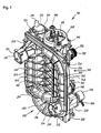
- Fig. 1 shows a hydraulic module 100 with a flow port 220, a first return port 210 and an alternative second return port 320.
- the first return port 210 has a stop 211 and a first port contour 212. Furthermore, a 3/2-way valve is provided.
- the hydraulic module consists of a first wall 200 and a second wall 300.
- the first wall 200 has a first conduit wall 201 of a conduit inlet 230, and a second conduit wall 202 of a conduit outlet 240.
- the first conduit wall 201 has an angled portion with a radius the bend is executed approximately at right angles.
- the line inlet 230 leads to a cavity 160. From the cavity 160, the line outlet 240 leads to the first return connection 210 and to the second return connection 320.
- the cavity 160 has a first outer wall 260.
- Return port 210 and the second return port 320 are each configured with an outer contour 221 for a securing element, for example a security wire.
- a base surface 223 is provided, on which there is, so to speak, the flow connection 220, which is integrally integrated into the hydraulic module.
- different ribs are attached to the first wall, for example, there is a rib 205, a longitudinal rib 209 and other ribs. These ribs have in common that they contribute to the strengthening and stiffening of the hydraulic module.
- a rib ring 207 a total of six ribs run together in the exemplary embodiment.
- the hydraulic module has a first web 250 for a welding flange.
- a tab 270 is provided with a mounting hole 271.
- a volumetric flow sensor 341 with a clamp 342 is held on a sensor receptacle 340.
- a servomotor 332 is mounted with connecting leads 333.
- the valve drive 332 opens the flow either through the first return port 210 or the second return port 320.
- a flange 390 with a pipe 391 is provided for a safety valve 392 with a knob 393.
- a heating flange 400 is introduced in the cavity 160.
- This heating flange 400 is fastened with a fastening ring 430 on the hydraulic module by means of fastening screws 440.
- a protective conductor tab 420 with a bore 421 is attached to the heating flange 400.
- the automatic ventilator 372 is connected to the hydraulic module 100 by means of a securing clamp 371 and secured thereto.
- the automatic air vent has a screw cap 374.
- first wall 200 is configured with stiffening ribs 206, of which partially four stiffening ribs and two longitudinal ribs 209 run on a rib ring 207 and are connected thereto.
- the rib ring 207 serves to receive forces that act on the rib ring from the stiffening ribs 206 and the longitudinal ribs 209. With the rib ring 207 in particular voltages are reduced. In particular, if less than six ribs, z. B. four ribs run to a point and are connected to a rib node 208 is provided there.
- the flow connection 22 0 has a Auskemung 224 to avoid accumulation of material in the plastic part.
- the second return connection 320 has a second connection contour 321. Standing up in the area of the heating flange 400, the connection spades 411 of the heating flange 400 are attached.
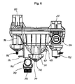
- second wall shows the integration of various components.
- a drainage flange 310 which has a second 1/4 rotary nut 311 with which a sealing plug 312 is fixed in the drainage flange 310.
- the first web 250 of the welding flange is below the drainage flange.
- the second wall 300 has various stiffening ribs 306 and others as shown in the figure.
- a mirror 305 is provided, to which the article identification and serial number and the like can be applied as a sticker, imprint or embossing.
- the second wall 300 forms a third conduit wall 301 of the conduit inlet 230 and a fourth conduit wall for the conduit outlet 240.
- a second outer wall 360 of the cavity 160 is formed.
- connection 350 for an additional measurement technique is provided in the second outer wall 360.
- This port if not used for additional metrology, is also sealed with a sealing plug 312 secured with a 1/4 turn nut 311.
- this connection is permanently closed by spraying with plastic material.
- the servomotor 332 with its connection lines 333 is fastened to the hydraulic module 100 by means of servomotor screws 334.
- the valve drive 330 is fastened in particular to a valve seat 331.
- the guide tube 380 for a temperature sensor is sealed in the embodiment with a plug 381 which is fixed with a first 1/4 rotary nut 382, watertight.
- the safety valve 392 is held in the flange 390 with a securing bracket 394.
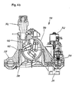
- FIG. 4a shown hydraulic module shows the heating flange 400 with a plurality of tubular heating elements 410. These are shown with corresponding connection spade 411 in the form of a blade receptacle or a screw eye or other attachment for electrical connections.
- the fastening ring 430 for fastening the heating flange 400 in the hydraulic module 100 has three struts 431, which run onto a ring 433 in the middle of the fastening ring 430.
- the ring 433 has an annular hole 432 for a sensor pebble, eg a temperature sensor or safety temperature limiter.
- the sensor bulb not shown, is through pushed the ring 433 in a protective tube 436, which is located behind the ring hole 432.
- the hydraulic module 100 has further stiffeners 225, e.g. Support the flow connection 220 and other connections.
- the first wall 200 and the second wall 300 have a common welding surface 110 or a so-called welding flange.
- the flange 390 is provided with a pipe piece 391 for the safety valve 392.
- the pipe section 391 is in the embodiment, a one-story extension of the flange 390th
- the flange 390 for the safety valve 392 has a drain port 395.
- the first wall 200 and the second wall 300 are joined together at the welding surface 110, and an edge 120 of the mold separation can be seen.
- the protective conductor tab 420 has a bore 421 for attachment of a protective conductor.
- the hydraulic module 100 is shown with a first welding flange 111.
- the first welding flange is formed by a welding surface 203 of the first wall 200 and by a second welding surface 303 of the second wall 300.
- a first cavity 112 is formed by the boundary with a first catching rib 113.
- a second welding flange 114 is formed between a third welding surface 204 and a fourth welding surface 304.
- a second cavity 115 is provided into which, for example, welding material can be displaced.
- the second cavity 115 is bounded by a second catching rib 116.
- a center cavity 117 is arranged, which is also provided for receiving welding material and for tolerance compensation of the first wall 200 to the second wall 300 and the welding amplitude, the vibration welding in a direction up to 1 mm, ensure.
- the drainage flange 310 is sealed with an O-ring 313.
- In the cavity 160 at least one tubular heater 410 is arranged.
- a float chamber 150 is arranged with a highest point 151, here air can be discharged with the automatic bleeder 370 from the hydraulic module 100.
- the float chamber 150 and the highest point 151 are connected via an opening 140 to the heating flow 130.
- the heating flange according to Fig. 8 has a plurality of tubular heating elements 410, which have a connection spade 411 or a screw eye.
- the fastening ring 430, the struts 431, points to the struts 431 in the embodiment at least one cable hook 434 and at least one cable web 435. With the cable hook 434 and the cable web 435 in particular electrical connection lines or sensor capillary can be held on the struts 431.
- Wings 437 are used to attach the mounting ring 430 on the hydraulic module 100, whereby the heating flange 400 is held in the hydraulic module.
- a section through the heating flange 400 is shown.
- the tubular heater 410 shown in section has a radiator pin 414, to which the connection spades 411 can be attached.
- the tubular heating element 410 is internally filled with a MgO insulation 413 and provided with a closure 412.
- a protective tube 436 is attached, which is connected in a watertight and pressure-tight manner with the heating flange. It is open to the ring hole 432 whereby a sensor bulb, for example, a temperature sensor can be inserted through the ring hole 432 in the protective tube 436.
- a catch hook or a similar connection for adapting and fixing a sensor bulb is still provided on the heating flange 400.
- the line feed 240 which is in Fig. 10 is shown leads into the cavity 160, in which the tubular heating elements 410 are located. Furthermore, the first welding flange 111 and the second welding flange 114 are shown.
- the sealing plug 312 is shown for the drainage flange. It has a hook 3121 for latching.
- the sealing plug is formed by a ring cover 3122, which has a web ring 3123, a stub ring 3124 and a cavity 3125. Furthermore, a pin 3126 is provided. This is the same snap hook as 3121, only in a different view.
- the plug has a total of four evenly distributed over the circumference.
- the seal is made in the embodiment with a fourth O-ring 313rd
- Fig. 12 shows how a pipe 500, in particular copper pipe, in a first return port 210, a flow port 220 and / or a second return port 320 is inserted.
- the tube 500 has a brass fitting 501, which is fastened to the tube 500 with a solder connection 502.
- a fifth O-ring 505 is inserted for sealing.
- the pipe 500 which may be a flow or return pipe of a heat pump, is attached and secured to the first return port 320, the forward port 220, or the second return port 320 with a backup wire 222.
- the fuse wire 222 is advantageously universal for all terminals and Additional components can be used for securing. Alternatively, a fastening hook, a screw or the like may be used.
- Fig. 13 shows a heat pump 10 with a frame 11.
- a refrigerant circuit 60 having a compressor 61, a condenser 62, an evaporator 63, an expansion valve 64, a sight glass 65, a dryer 66, a suction line 67 and a hot gas line 68 is shown
- an expansion tank 50 for the heating and an expansion tank 53 for the heat source are provided in the upper part of the frame.
- the expansion tank 50 for the heater is coupled to a first vibration damper 51 of the heat pump 10.
- a cap valve 52 is connected to the expansion tank 53 of the heat source.
- a second vibration damper 54 is attached to the expansion tank 53 of the heat source.
- the hydraulic module 100 is connected to a first return port 210 of the hydraulic module 100 at a return line, not shown, and the feed line (not shown) of the heat pump is connected to a flow port 220 of the hydraulic module 100. Furthermore, the heat pump still has a flow pump 40 for the brine and a flow pump 31 for the heating and hot water.
- the hydraulic module 100 is equipped with at least one temperature sensor 71, which is connectable to a not shown control of the heat pump. Also connected to the regulator is the valve drive 332, with which the quantities of water are controlled by the hydraulic module 100 and / or the flow through the heating or the hot water system. Furthermore, the at least one tubular heater 410 of the heating flange 400 of the hydraulic module 100 is connected to a switching device or is controlled by the controller. To connect a heater and a hot water system, not shown, the heat pump 10 lines 43 for hot water and heating. Lines 42 are provided for the brine connection of the heat source.
- the evaporator In an air / water heat pump, the evaporator is flowed through by an air flow, which gives off heat to the evaporator flowing through the refrigerant. Therefore, the evaporator of an air heat pump is usually mounted in another room where the air flows as a heat source.
- a brine / water heat pump is shown, in which a brine, which usually absorbs heat from the soil, is provided as the heat source. The brine flows through here in the same room mounted evaporator 63.
Abstract
Description
- Die Erfindung betrifft ein Hydraulikmodul für ein Haustechnikgerät mit wenigstens einem Vorlaufanschluss und wenigstens einem ersten Rücklaufanschluss, durch das ein Fluid leitbar ist, und eine Wärmepumpe mit einem Kältemittelkreislauf, mit einem Verdichter, einem Verflüssiger, einem Verdampfer und einem Expansionsventil.
- Bekannt ist aus
DE 32 14 775 A1 eine Vorrichtung zum Übergeben von Wärme von einer Versorgungsleitung zu einem Abnehmer. Die Vorrichtung weist in Form einer Matrix angeordnete, sich zumindest teilweise schneidende Längs- und Querleitungen auf. - Eine Baueinheit einer Heizungsanlage mit zwei Heizkreisen ist aus
EP 1 884 723 B1 bekannt. Die Baueinheit besteht mindestens aus einem Kunststoffgehäuse-Bauteil mit einem Pumpenaggregat, mit einem Wärmetauscher für die Brauchwassererwärmung und mit weiteren elektrischen, mechanischen oder hydraulischen Komponenten, wobei die Baueinheit vier Gehäuseteile aufweist. - Aus
EP 1 447 627 B1 ist eine Vorrichtung zum Steuern und/oder Regeln für die Gebäudeheizung oder -kühlung mit einem Gehäuse bekannt. An der Außenseite des Gehäuses ist eine Mehrzahl von Anschlüssen für die Zu- und Ableitung von energietransportierenden Medien vorgesehen. Es handelt sich hierbei um eine Verteileinheit als vormontierte Baueinheit in einem Gehäuse. Das Gehäuse verfügt über ein erstes und zweites Gehäusesegment, wobei in dem ersten Gehäusesegment die hydraulischen Mittel zum Verteilen des durch Sonnenkollektoren erwärmten energietransportierenden Mediums angeordnet sind. - Eine Baueinheit für eine Kompaktheizungsanlage mit rückwärtigen Anschlüssen für einen Plattenwärmetauscher mit einem zentralen Pumpengehäuse ist aus
EP 1 528 330 B1 bekannt. Hierbei sind im Armaturengehäuse jeweils von vom zugängliche Einschubräume zur Aufnahme mindestens einer Armatur vorgesehen. - Eine Vorrichtung gemäß
DE 20 2008 003 241 U1 , die für ein Wärmemanagementsystem eines Raumes vorgesehen ist, ist mit Anschlüssen für wenigstens einen ersten, einen zweiten sowie einen dritten Kreislauf ausgestattet. In den Kreisläufen zirkuliert ein thermisch beanspruchbares Fluid, und die Vorrichtung ist als mechanisch abgeschlossene, einzeln handhabbare Baueinheit ausgebildet. Wenigstens ein Teil weist miteinander strömungstechnisch verschaltete Verbindungsleitungen auf. - Aufgabe der Erfindung ist es, ein kostengünstiges und effizientes Modul mit möglichst wenig Bauteilen bereitzustellen, bei dem der hydraulische Druckverlust bei einem hohen Volumenstrom von insbesondere mehr als 1 m3/h möglichst gering ist und welches insbesondere in ein Haustechnikgerät möglichst einfach ein- und ausbaubar ist.
- Gelöst ist die Aufgabe durch die Merkmale der Patentansprüche 1 oder 12.
- In vorteilhafter Weise ist ein entsprechendes Hydraulikmodul aus einem Gehäuse mit wenigstens einer ersten und einer zweiten Wand gebildet, die insbesondere jeweils spritzgegossen sind. Die erste und die zweite Wand bestehen vorteilhaft aus Kunststoff und werden miteinander verbunden, insbesondere mit einem Schweißverfahren, wie Vibrationsschweißen, Ultraschallschweißen, Reibschweißen oder auch Laserschweißen. Somit ergibt sich vorteilhaft durch die dauerhafte wasser- und druckdichte Verbindung der ersten mit der zweiten Wand eine Fluidführung mit wenigstens einer Kavität zur Aufnahme eines Bauteils, welches im Fluidstrom liegt. Die Wasserführung ist in der ersten und zweiten Wand für einen geringen internen Druckverlust optimiert. In der wenigstens einen Kavität ist in einem vorteilhaften Ausführungsbeispiel eine elektrische Zusatzbeheizung eingebaut. Dies ist insbesondere vorteilhaft bei einem Einsatz des Hydraulikmoduls in einer Wärmepumpe. Die Zusatzheizung wird z.B. für den Fall erhöhter Vorlauftemperatur oder zur Unterstützung einer Luft/Wasser-Wärmepumpe bei sehr kalten Außentemperaturen benutzt.
- Das Hydraulikmodul ist für einen Volumenstrom von insbesondere 1 - 40 m3/h ausgelegt, insbesondere 1,5 - 4 m3/h und speziell ca. 2 - 2,5 m3/h. Hierfür sind vorteilhafterweise Strömungsquerschnitte eines Leitungszulaufs und/oder eines Leitungsablaufs vorgesehen, die einem Rohr mit einem Durchmesser von ca. 1 - 8 cm entsprechen.
- Die Grundwandstärke des Hydraulikmoduls beträgt ca. 2 - 3,5 mm, insbesondere ca. 2,8 mm. Die Rippen können auch eine geringere Wandstärke aufweisen, insbesondere 1,5 mm. Mit der Grundwandstärke sind insbesondere die Wände der Kavität ausgestattet. So ist ein vorteilhafter Betriebsdruck von 1 - 5 bar möglich, insbesondere 3 bar. Das Sicherheitsventil ist im Ausführungsbeispiel auf 3 bar ausgelegt, es sind aber auch andere Drücke zwischen 0 und 10 bar möglich.
- Gemäß einem vorteilhaften Erfindungsgedanken weist das Hydraulikmodul für ein Haustechnikgerät wenigstens einen Vorlaufanschluss und wenigstens einen ersten Rücklaufanschluss auf, durch die ein Fluid leitbar ist. Eine Kavität ist wenigstens teilweise von einer ersten Wand des Hydraulikmoduls gebildet, und eine fluidleitende Verbindung der Kavität besteht mit dem Vorlaufanschluss und dem ersten Rücklaufanschluss.
- In vorteilhafter Weise ist die Kavität von der ersten Wand und einer zweiten Wand gebildet, und die erste Wand ist mit der zweiten Wand nach außen zumindest teilweise im Bereich der Kavität wasserdicht verbunden. Weiterhin ist ein Leitungszulauf mit dem Vorlaufanschluss, und ein Leitungsablauf mit wenigstens einem ersten Rücklaufanschluss zur Leitung eines Fluids verbunden.
- Bezüglich der Druckverluste 1st es besonders vortellhaft, wenn die Durchströmung des Hydraulikmoduls durch möglichst wenig Umlenkung erfolgt. Daher ist es von Vorteil, wenn der Vorlaufanschluss, der Leitungszulauf, die Kavität, der Leitungsablauf und der Rücklaufanschluss ohne oder mit möglichst wenigen Umlenkungen ausgestaltet sind. Dies ist allerdings aufgrund der Bauweise eines Haustechnikgerätes, in das das Hydraulikmodul eingesetzt wird, nicht immer möglich.
- Vorteilhaft ist es daher, wenn Leitungszulauf und/oder Leitungsablauf wenigstens eine Strömungsumkehr aufweisen und in der Nähe, insbesondere nahezu parallel oder In einem Winkel zur Kavität angeordnet sind.
- Der Vorlaufanschluss und/oder der Rücklaufanschluss ist in vorteilhafter Weise ohne eine Umlenkung mit dem Leitungszulauf und/oder dem Leitungsablauf verbunden.
- In einem anderen Ausführungsbeispiel sind der Vorlaufanschluss und/oder der Rücklaufanschluss in einem Winkel zum Leitungszulauf und/oder zum jeweiligen Leitungsablauf angeordnet. Hiermit ist es möglich, insbesondere waagerecht zulaufende Vorlaufleitungen und/oder Rücklaufleitungen des Haustechnikgerätes mit dem Hydraulikmodul zu verbinden. Diese zum Hautechnikgerät gehörenden Vorlauf- und/oder Rücklaufleitungen brauchen somit nicht extra abgewinkelt und in das Hydraulikmodul eingeführt zu werden. Alternativ kann das Haustechnikgerät einen flexiblen Schlauch aufweisen, insbesondere als Vorlauf- und/oder Rücklaufleitung.
- Bei einem vorteilhaften Hydraulikmodul ist ein Vorlaufanschluss rechtwinklig zu einem Leitungszulauf angeordnet. Dieser Leitungszulauf weist in Fluidrichtung weiterhin eine in etwa rechtwinklige Ablenkung auf, die mit einem Radius insbesondere von ca. 1 - 8 cm versehen ist. In Ergänzung oder alternativ hierzu ist der Rücklaufanschluss längs zum Leitungsablauf angeordnet, wobei der Leitungsablauf in vorteilhafter Weise wenigstens eine weitere Abwinklung aufweist.
- Der Leitungszulauf und der Leitungsablauf sind vorteilhafterweise seitlich an die Kavität, in der der Zusatzheizkörper liegt, angeschlossen. Strömungstechnisch günstiger ist es allerdings, wenn die Kavität weitgehend ohne Abwinklung ist und ohne Umlenkung des Fluids durchströmt wird. Der Zusatzheizkörper besteht vorteilhaft aus wenigstens einem Rohrheizkörper, Plattenheizkörper oder einem anderen elektrischen Heizkörper mit einer Heizleistung von vorteilhaft 1 - 20 kW, insbesondere ca. 3 -12 kW.
- Vorteilhaft ist es, wenn der Vorlaufanschluss und/oder der Rücklaufanschluss in der ersten und/oder der zweiten Wand angeordnet sind und der Leitungszulauf von einer ersten und einer dritten Leitungswand, und/oder von einer zweiten und einer vierten Leitungswand gebildet sind.
- Gemäß einem weiteren Gedanken der Erfindung ist in der fluidleitenden Verbindung zwischen dem Vorlaufanschluss und wenigstens dem ersten Rücklaufanschluss wenigstens ein weiteres Bauteil angeordnet, insbesondere eine Aufnahme, ein Flansch, ein Führungsrohr, ein Drainageflansch, eine Sensoraufnahme und/oder ein zweiter Rücklaufanschluss.
- Die Aufnahme ist hierbei insbesondere als rohrförmige Kavität vorgesehen, die in fluidführender Verbindung mit dem Leitungszulauf, dem Leitungsablauf, dem Vorlaufanschluss, dem Rücklaufanschluss und/oder der Kavität steht. Die Aufnahme dient, wie das Wort schon sagt, der Aufnahme von weiteren Komponenten, wie z.B. Sensoren, Fühlern, Aktoren wie Ventile oder z.B. einem Automatikentlüfter oder einfach einem Schauglas. Diese Komponenten können In die Aufnahme bzw. in eine der Aufnahmen eingesetzt werden. Sie werden hierbei in vorteilhafter Weise mit einem kleinen Bügel befestigt. Vorteilhaft ist weiterhin, wenn der Bügel für alle Aufnahmen der gleiche ist.
- Vorteilhaft ist in einer Sensoraufnahme ein Durchflussensor eingesetzt, zur Messung des Fluld-Durchflusses durch das Hydraulikmodul.
- Eine vorteilhafte Aufnahme ist durch ein Führungsrchr gebildet, welches insbesondere für einen Temperatursensor, einen Sicherheitstemperaturbegrenzer (STB) oder auch einen anderen Sensor oder Aktoren vorgesehen ist Der Temperatursensor wird in das Führungsrohr eingeschoben, bis er im fluidführenden Bereich positioniert ist. Die Adaptierung erfolgt in vorteilhafter Weise ebenfalls mit einem Befestigungsbügel, wie er für alle Aufnahmen vorteilhaft gleichförmig ausgebildet ist. Die Betriebstemperatur, die für das Hydraulikmodul ausgelegt ist, beträgt ca. 60-100 °C, insbesondere ca. 75 °C. Die Abschalttemperatur des STB beträgt ca. 85 °C.
- Der Flansch ist dafür vorgesehen, ein Sicherheitsventil aufzunehmen. Er ist vorteilhaft rohrförmig in der ersten oder zweiten Wand des Hydraulikmoduls gebildet In diese Aufnahme wird z. B. ein handelsübliches Sicherheitsventil eingesteckt. Vorteilhaft ist es, wenn an dem Flansch eine Ablassöffnung für Fluid jeglicher Art vorgesehen ist, das im Sicherheitsfall vom Sicherheitsventil freigegeben wird.
- Der Drainageflansch ist insbesondere dann erforderlich, wenn das Hydraulikmodul im fluidführenden Bereich Abwinklungen von mehr als 90° aufweist, so dass Räume entstehen, in denen sich schwerere Bestandteile als Wasser absetzen können. Daher ist es vorteilhaft, einen Drainageflansch im Hydraulikmodul vorzusehen, der zum Ablassen der Bestandteile geöffnet wird.
- Vorteilhaft ist ein Hydraulikmodul, bei dem die Kavität dafür vorgesehen ist, einen Heizkörper aufzunehmen, oder der Heizkörper in der Kavität angeordnet ist und die Kavität insbesondere durch einen Heizflansch wasserdicht und druckdicht verschlossen ist.
- Gemäß einem weiteren Gedanken der Erfindung ist der Heizflansch mit einem Befestigungsring an der ersten und/oder der zweiten Wand insbesondere wasserdicht befestigt
- In dem Fall, wenn das Fluid im Hydraulikmodul umgelenkt wird, insbesondere die Strömungsrichtung von oben nach unten durch das Hydraulikmodul wechselt, ist es von Vorteil, wenn das Hydraulikmodul eine Schwimmerkammer für einen Automatikentlüfter aufweist, wobei die Schwimmerkammer vorteilhaft eine höchste Stelle aufweist, die dafür vorgesehen ist, oben im Gerät zu liegen, wenn das Gerät senkrecht montiert ist. Bilden sich in einer Umlenkung für das Fluid Gasblasen, verlassen diese über den Automatikentlüfter das Hydraulikmodul.
- Vorteilhafte Materialien für die erste Wand und/oder die zweite Wand ist Kunststoff, insbesondere PA66, SPS-GF30, PPE/PS-GF30, PA6T/61-GF40 oder PEI-GF30.
- Gemäß einem weiteren Gedanken der Erfindung weist die erste und/oder die zweite Wand äußere Verstärkungen auf, insbesondere teilweise hohe Rippen. Auf einer ersten Außenwand und/oder einer zweiten Außenwand laufen mehrere Rippen, insbesondere sechs Rippen, auf einen Rippenring zu. Andere Rippen, insbesondere weniger als sechs Rippen, laufen in einem Rippenknoten zusammen.
- Gemäß einem vorteilhaften Ausführungsbeispiel variieren die Rippen in der einen Höhe, insbesondere von ca. 1 - 40 mm, wobei sie eine Materialdicke von ca. 0,3 - 5 mm, insbesondere ca. 1 mm aufweisen.
- Vorteilhaft ist es weiterhin, dass die erste und die zweite Wand miteinander verschweißt sind, insbesondere druckdicht und wasserdicht durch Vibrationsschweißen, Reibschweißen, Ultraschallschweißen oder Laserschweißen in einer Schweißfläche.
- Mit dem 3/2-Wegeventil wird die Wärmenutzungsseite des Haustechnikgerätes, insbesondere bei einer Wärmepumpe, zwischen Heizungsbetrieb und Warmwasserbereitung umgeschaltet. Daher weist das Hydraulikmodul den ersten Rücklaufanschluss und den zweiten Rücklaufanschluss auf. Hier werden jeweils die Rücklaufleitungen von der Heizung und der Warmwasseranlage angeschlossen. Diese können auch im Haustechnikgerät angeordnet sein. Mit dem 3/2-Wegeventil wird nun zwischen dem Heizungsanschluss und dem Warmwasseranschluss umgeschaltet. Der Vorlaufanschluss führt in vorteilhafter Weise das Fluid aus der Heizung und/oder der Warmwasseranlage zu einem Wärmetauscher des Haustechnikgerätes. Dort wird das Wasser erwärmt und fließt dann wieder in die Heizung oder die Warmwasserbereitung.
- Gemäß einem alternativen Gedanken der Erfindung können auch mehrere Vorlaufanschlüsse und insbesondere ein Rücklaufanschluss vorgesehen sein. Dann fließt das Wärmeträgerfluid erst durch einen Wärmetauscher des Haustechnikgerätes, wird dort erwärmt und dann erfolgt mit dem 3/2-Wegeventil die Verteilung zum Heizsystem oder zur Warmwasserbereitung.
- Vorteilhaft ist es weiterhin, eine Wärmepumpe mit einem Hydraulikmodul zu verbinden oder das Hydraulikmodul in eine Wärmepumpe einzubauen, insbesondere wie oben beschrieben mit einem 3/2-Wegeventil.
- Vorteilhaft ist eine Wärmepumpe mit einem Kältemittelkreislauf, mit einem Verdichter, einem Verflüssiger, einem Verdampfer und einem Expansionsventil mit einem Hydraulikmodul ausgestaltet, wobei ein Vorlaufanschluss mit einer Vorlaufleitung der Wärmepumpe und wenigstens ein erster Rücklaufanschluss mit einer Rücklaufleitung der Wärmepumpe zumindest fluidtechnisch in Verbindung stehen.
- Der Vorlaufanschluss des Hydraulikmoduls ist in einem anderen vorteilhaften Fall mit einem Verflüssigerwärmetauscher der Wärmepumpe verbunden, die beiden Rücklaufanschlüsse (Heizung und Warmwasser) sind dann die jeweiligen Vorlaufanschlüsse für Heizkreis und Warmwasser-Speicherladekreis.
- Gemäß einem weiteren Gedanken der Wärmepumpe sind die wesentlichen Komponenten der Wasserführung in dem Hydraulikmodul integriert und bilden eine Einheit.
- Die Vorlaufleitung oder eine Leitung, die mit dem Wärmetauscher der Wärmepumpe verbunden ist, ist in einem vorteilhaften Ausführungsbeispiel in den Vorlaufanschluss des Hydraulikmoduls eingesteckt und/oder die Rücklaufleitung ist in den Rücklaufanschluss eingesteckt. Insbesondere ist mittels eines Dichtkörpers, wie einem O-Ring, zwischen der Leitung und dem Vorlaufanschluss und/oder dem Rücklaufanschluss eine wasserdichte Abdichtung vorhanden.
- Gemäß einem vorteilhaften Gedanken der Erfindung sind der Rücklaufanschluss und der Vorlaufanschluss auf einer Seite des Hydraulikmoduls oder in einer Richtung angeordnet. In einer entsprechenden Wärmepumpe, in die das Hydraulikmodul in vorteilhafter Weise eingesetzt ist, sind die zum Rücklauf- und zum Vorlaufanschluss korrespondierenden Vorlaufleitungen und wenigstens eine Rücklaufleitung ebenfalls auf einer Seite bzw. in einer Richtung angeordnet, so dass das Hydraulikmodul in einem Arbeitsgang auf die Wärmepumpe bzw. auf den Vorlauf und den wenigstens einen Rücklauf der Wärmepumpe aufgeschoben wird. Damit ist das Hydraulikmodul auch gleichzeitig in der Wärmepumpe arretiert. Eine vorteilhafte Ausgestaltung des Hydraulikmoduls ist hierbei die Anordnung des Leitungsablaufs und des Leitungszulaufs im Bereich der Kavität, wodurch das Modul weitgehend kompakt ist, allerdings eine oder mehrere Ablenkungen in Strömungsrichtung vorgesehen sind. Es ist aber auch ein Hydraulikmodul mit einer geringen oder mit gar keiner Ablenkung im Strömungsschluss verwendbar.
- In vorteilhafter Weise wird das Hydraulikmodul über ein Loch in einer Lasche mit der Wärmepumpe verbunden. Im oben beschriebenen Fall reicht es aber aus, das Hydraulikmodul mit der Vorlauf- und Rücklaufleitung der Wärmepumpe zu verbinden. Hierzu weist vorteilhaft wenigstens die Vorlauf- und/oder Rücklaufleitung einen ringförmigen Absatz auf, hinter den ein Befestigungsbügel greift, um das Hydraulikmodul mit der Wärmepumpe zu sichern.
- Gemäß einem weiteren Erfindungsgedanken ist ein Ende der Vorlaufleitung und ein Ende der Rücklaufleitung der Wärmepumpe gegenüberliegend angeordnet, so dass das Hydraulikmodul zwischen dem Ende der Vorlaufleitung und dem Ende der Rücklaufleitung angeordnet wird. Hierbei ist insbesondere eine Ausführung des Hydraulikmoduls mit wenigen inneren Umlenkungen in der Strömungszuführung von Vorteil. Im Fluidfluss, ausgehend vom Ende des Rücklaufanschlusses, fließt das Fluid dann weitgehend geradlinig durch das Hydraulikmodul, um dann am Ende der Vorlaufleitung wieder in die Wärmepumpe einzutreten.
- Die Wärmepumpe weist in vorteilhafter Weise eine Rücklaufleitung für das Heizungsfluid und eine Rücklaufleitung für das Warmwasserfluid auf, die beide an das Hydraulikmodul angeschlossen sind, insbesondere an den ersten Rücklaufanschluss und den zweiten Rücklaufanschluss. Alternativ können auch zwei Vorlaufanschlüsse genommen werden.
- Ein Regler der Wärmepumpe ist mit wenigstens einem in das Hydraulikmodul eingeschobenen oder damit in Kontakt stehenden Temperaturfühler und weiterhin mit dem Durchflusssensor verbunden. Der Heizkörper und das 3/2-Wegeventil sind ebenfalls mit der Regelung verbunden und werden insbesondere von der Regelung angesteuert oder geregelt.
- Die Figuren zeigen
- Figur 1
- ein Hydraulikmodul mit einem Heizflansch,
- Figur 2
- das Hydraulikmodul mit einer ersten Wand,
- Figur 3
- das Hydraulikmodul mit einer zweiten Wand,
- Figur 4a
- eine Ansicht des Hydraulikmoduls, insbesondere auf dem Heizflansch,
- Figur 4b
- einen Schnitt durch die Kavität,
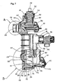
- Figur 5
- eine Seitenansicht des Hydraulikmoduls auf dem Flansch für das Sicherheitsventil,
- Figur 6
- eine Ansicht von unten auf das Hydraulikmodul,
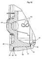
- Figur 7
- eine teilweise Schnittdarstellung durch das Hydraulikmodul mit Sicht in die Kavität,
- Figur 8
- den Heizflansch,
- Figur 9
- einen Schnitt durch den Heizflansch,
- Figur 10
- den Schweißflansch,
- Figur 11
- den Stopfen,
- Figur 12
- Vorlaufanschluss/Rücklaufanschluss,
- Figur 13
- die Wärmepumpe mit Hydraulikmodul.
-
Fig. 1 zeigt ein Hydraulikmodul 100 mit einem Vorlaufanschluss 220, einem ersten Rücklaufanschluss 210 und einem alternativen zweiten Rücklaufanschluss 320. Der erste Rückaufanschluss 210 weist einen Anschlag 211 auf sowie eine erste Anschlusskontur 212. Weiterhin ist ein 3/2-Wegeventil vorgesehen. Das Hydraulikmodul besteht aus einer ersten Wand 200 und einer zweiten Wand 300. Die erste Wand 200 weist eine erste Leitungswand 201 eines Leitungszulaufs 230 auf, sowie eine zweite Leitungswand 202 eines Leitungsablaufs 240. Die erste Leitungswand 201 weist eine Abwinklung mit einem Radius auf, wobei die Abwinklung in etwa rechtwinklig ausgeführt ist. Der Leitungszulauf 230 führt zu einer Kavität 160. Von der Kavität 160 führt der Leitungsablauf 240 zum ersten Rücklaufanschluss 210 und zum zweiten Rücklaufanschluss 320. Die Kavität 160 weist eine erste Außenwand 260 auf. Der Vorlaufanschluss 220 sowie der erste - Rücklaufanschluss 210 und der zweite Rücklaufanschluss 320 sind jeweils mit einer Aussenkontur 221 für ein Sicherungselement, z.B. einen Sicherungsdraht ausgestaltet. Am Vorlaufanschluss 220 ist eine Grundfläche 223 vorgesehen, auf dieser steht sozusagen der Vorlaufanschluss 220, der einstückig in das Hydraulikmodul eingebunden ist. In
Fig. 1 sind an der ersten Wand 200 verschiedene Rippen angebracht, beispielsweise ist eine Rippe 205, eine Längsrippe 209 und weitere Rippen vorhanden. Diese Rippen haben gemeinsam, dass sie zur Stärkung und Versteifung des Hydraulikmoduls beitragen. In einem Rippenring 207 laufen im Ausführungsbeispiel insgesamt sechs Rippen zusammen. Weiterhin weist das Hydraulikmodul einen ersten Steg 250 für einen Schweißflansch auf. Zur Befestigung des Hydraulikmoduls 100 z.B. an einem Haustechnikgerät ist eine Lasche 270 mit einer Befestigungsbohrung 271 vorgesehen. - An einer Sensoraufnahme 340 ist ein Volumenstromsensor 341 mit einer Klammer 342 gehalten. In einer Aufnahme 330 für einen Ventilantrieb ist ein Stellmotor 332 mit Anschlussleitungen 333 angebracht. Der Ventilantrieb bzw. der Stellmotor 332 öffnet den Durchfluss entweder durch den ersten Rücklaufanschluss 210 oder den zweiten Rücklaufanschluss 320. Ein Flansch 390 mit einem Rohrstück 391 ist für ein Sicherheitsventil 392 mit einem Drehknopf 393 vorgesehen.
- In die Kavität 160 ist ein Heizflansch 400 eingebracht. Dieser Heizflansch 400 ist mit einem Befestigungsring 430 am Hydraulikmodul mittels Befestigungsschrauben 440 befestigt. Zur elektrischen Sicherheit ist an den Heizflansch 400 eine Schutzleiterlasche 420 mit einer Bohrung 421 angebracht.
- Ebenfalls in das Hydraulikmodul 100 integriert ist eine Aufnahme 370 für einen Automatikentlüfter 372. Der Automatikentlüfter 372 ist mittels einer Sicherungsklemme 371 mit dem Hydraulikmodul 100 verbunden und mit diesem gesichert. Der Automatikentlüfter weist einen Schraubdeckel 374 auf.
- Die in
Fig. 2 dargestellte erste Wand 200 ist mit Versteifungsrippen 206 ausgestaltet, von denen teilweise vier Versteifungsrippen und zwei Längsrippen 209 auf einen Rippenring 207 zulaufen und mit diesem verbunden sind. Der Rippenring 207 dient zur Aufnahme von Kräften, die aus den Versteifungsrippen 206 und den Längsrippen 209 auf den Rippenring wirken. Mit dem Rippenring 207 werden insbesondere Spannungen abgebaut. Insbesondere wenn weniger als sechs Rippen, z. B. vier Rippen auf einen Punkt zulaufen und damit verbunden sind, ist dort ein Rippenknoten 208 vorgesehen. Der Vorlaufanschluss 22 0 weist eine Auskemung 224 zur Vermeidung einer Materialanhäufung im Kunststoffteil auf. Im ersten Rücklaufanschluss 210 ist ein Dichtkegel 213 eines 3/2-Wegeventils zu sehen. Der zweite Rücklaufanschluss 320 weist eine zweite Anschlusskontur 321 auf. Hochstehend im Bereich des Heizflansches 400 sind die Anschlussspaten 411 des Heizflansches 400 angebracht. - Die in
Fig. 3 insbesondere dargestellte zweite Wand zeigt die Integration verschiedener Bauteile. Unten befindet sich ein Drainageflansch 310, der mit einer zweiten 1/4-Drehmutter 311, mit der ein Dichtstopfen 312 im Drainageflansch 310 befestigt ist, aufweist. Unterhalb des Drainageflansches befindet sich der erste Steg 250 des Schweißflansches. Auch die zweite Wand 300 weist verschiedene Versteifungsrippen 306 und weitere, wie in der Figur gezeigt, auf. Weiterhin ist ein Spiegel 305 vorgesehen, auf den die Artikelkennzeichnung sowie Seriennummer und dergleichen als Aufkleber, Aufdruck oder Prägung aufgebracht werden können. Die zweite Wand 300 bildet eine dritte Leitungswand 301 des Leitungszulaufs 230 sowie eine vierte Leitungswand für den Leitungsablauf 240. In der zweiten Wand 300 ist eine zweite Außenwand 360 der Kavität 160 ausgebildet. Im Ausführungsbeispiel ist in der zweiten Außenwand 360 ein Anschluss 350 für eine zusätzliche Messtechnik vorgesehen. Dieser Anschluss wird, wenn er nicht für zusätzliche Messtechnik verwendet wird, ebenfalls mit einem Dichtstopfen 312 verschlossen, der mit einer 1/4-Drehmutter 311 befestigt ist. Alternativ ist dieser Anschluss dauerhaft durch Verspritzen mit Kunststoffmaterial verschlossen. - Der Stellmotor 332 mit seinen Anschlussleitungen 333 ist mittels Stellmotorschrauben 334 am Hydraulikmodul 100 befestigt. Der Ventilantrieb 330 ist insbesondere an einem Ventilsitz 331 befestigt. Das Führungsrohr 380 für einen Temperaturfühler ist im Ausführungsbeispiel mit einem Stopfen 381, der mit einer ersten 1/4-Drehmutter 382 befestigt ist, wasserdicht verschlossen. Das Sicherheitsventil 392 ist mit einem Sicherungsbügel 394 im Flansch 390 gehalten.
- Das in
Fig. 4a gezeigte Hydraulikmodul zeigt den Heizflansch 400 mit mehreren Rohrheizkörpern 410. Diese sind mit entsprechenden Anschlussspaten 411 in Form einer Flachsteckhülse oder einer Schrauböse oder einer anderen Befestigung für elektrische Anschlüsse gezeigt. Der Befestigungsring 430 zur Befestigung des Heizflansches 400 im Hydraulikmodul 100 weist drei Streben 431 auf, die auf einen Ring 433 in der Mitte des Befestigungsrings 430 zulaufen. Der Ring 433 weist ein Ringloch 432 für eine Fühlerbime, z.B. einen Temperaturfühler oder Sicherheitstemperaturbegrenzer, auf. Die nicht dargestellte Fühlerbirne wird durch den Ring 433 in ein Schutzrohr 436 geschoben, das sich hinter dem Ringloch 432 befindet. - Das Hydraulikmodul 100 weist weitere Versteifungen 225 auf, die z.B. den Vorlaufanschluss 220 und andere Anschlüsse stützen. Die erste Wand 200 und die zweite Wand 300 weisen eine gemeinsame Schweißfläche 110 bzw. einen sogenannten Schweißflansch auf. Der Flansch 390 ist mit einem Rohrstück 391 für das Sicherheitsventil 392 versehen. Das Rohrstück 391 ist im Ausführungsbeispiel eine einstöckige Verlängerung des Flansches 390.
- In
Fig. 5 weist der Flansch 390 für das Sicherheitsventil 392 eine Ablassöffnung 395 auf. Die erste Wand 200 und die zweite Wand 300 sind an der Schweißfläche 110 zusammengefügt, und eine Kante 120 der Formtrennung ist zu sehen. Die Schutzleiterlasche 420 weist eine Bohrung 421 zur Befestigung eines Schutzleiters auf. - In
Fig. 7 ist das Hydraulikmodul 100 mit einem ersten Schweißflansch 111 gezeigt. Der erste Schweißflansch ist gebildet durch eine Schweißfläche 203 der ersten Wand 200 und durch eine zweite Schweißfläche 303 der zweiten Wand 300. Im Bereich des ersten Schweißflansches ist eine erste Kavität 112 durch die Begrenzung mit einer ersten Fangrippe 113 gebildet. Ein zweiter Schweißflansch 114 ist zwischen einer dritten Schweißfläche 204 und einer vierten Schweißfläche 304 gebildet. Hier ist eine zweite Kavität 115 vorgesehen, in die z.B. Schweissgut verdrängt werden kann. Die zweite Kavität 115 ist durch eine zweite Fangrippe 116 begrenzt. Zwischen dem ersten Schweißflansch 111 und dem zweiten Schweißflansch 114 ist eine Mittenkavität 117 angeordnet, die auch zur Aufnahme von Schweissgut und zum Toleranzausgleich der ersten Wand 200 zur zweiten Wand 300 vorgesehen ist und um die Schweißamplitude, die beim Vibrationsschweißen in eine Richtung bei bis zu 1 mm liegen kann, sicherzustellen. Der Drainageflansch 310 ist mit einem O-Ring 313 abgedichtet. In der Kavität 160 ist wenigstens ein Rohrheizkörper 410 angeordnet. - Im Hydraulikmodul ist eine Schwimmerkammer 150 mit einer höchsten Stelle 151 angeordnet, hier kann Luft mit dem Automatikentlüfter 370 aus dem Hydraulikmodul 100 abgelassen werden. Die Schwimmerkammer 150 und die höchste Stelle 151 sind über eine Öffnung 140 mit dem Heizungsvorlauf 130 verbunden.
- Der Heizflansch gemäß
Fig. 8 weist mehrere Rohrheizkörper 410 auf, die einen Anschlussspaten 411 oder eine Schrauböse aufweisen. Der Befestigungsring 430, der Streben 431 aufweist, weist auf den Streben 431 im Ausführungsbeispiel wenigstens einen Leitungshaken 434 auf sowie wenigstens einen Leitungssteg 435. Mit dem Leitungshaken 434 und dem Leitungssteg 435 können insbesondere elektrische Anschlussleitungen oder Fühlerkapillare an den Streben 431 gehalten werden. Flügel 437 dienen der Befestigung des Befestigungsrings 430 am Hydraulikmodul 100, womit der Heizflansch 400 im Hydraulikmodul gehalten ist. - In
Fig. 9 ist ein Schnitt durch den Heizflansch 400 gezeigt. Der gezeigte Rohrheizkörper 410 im Schnitt weist einen Heizkörperbolzen 414 auf, an dem die Anschlussspaten 411 befestigt werden können. Der Rohrheizkörper 410 ist innen mit einer MgO-lsolierung 413 ausgefüllt und mit einem Abschluss 412 versehen. An dem Heizflansch 400 ist ein Schutzrohr 436 angebracht, welches wasser- und druckdicht mit dem Heizflansch verbunden ist. Es ist zum Ringloch 432 geöffnet wodurch eine Fühlerbirne z.B. eines Temperatursensors durch das Ringloch 432 in das Schutzrohr 436 eingeführt werden kann. In vorteilhafter Weise ist an dem Heizflansch 400 noch ein Rasthaken oder eine ähnliche Verbindung zur Adaptierung und Fixierung einer Fühlerbirne vorgesehen. - Der Leitungszulauf 240, der in
Fig. 10 gezeigt ist, führt in die Kavität 160, in der die Rohrheizkörper 410 liegen. Weiterhin ist der erste Schweißflansch 111 sowie der zweite Schweißflansch 114 gezeigt. - In
Fig. 11 ist der Dichtstopfen 312 für den Drainageflansch dargestellt. Er weist einen Haken 3121 zum Verrasten auf. Der Dichtstopfen ist durch einen Ringdeckel 3122 gebildet, der einen Stegring 3123, einen Stumpfring 3124 sowie einen Hohlraum 3125 aufweist. Weiterhin ist ein Zapfen 3126 vorgesehen. Das ist der gleiche Rasthaken wie 3121, nur in einer anderen Ansicht. Der Stopfen hat insgesamt vier davon gleichmäßig über den Umfang verteilt. Die Abdichtung erfolgt im Ausführungsbeispiel mit einem vierten O-Ring 313. -
Fig. 12 zeigt, wie ein Rohr 500, insbesondere Kupferrohr, in einem ersten Rücklaufanschluss 210, einem Vorlaufanschluss 220 und/oder einem zweiten Rücklaufanschluss 320 eingesetzt ist. Das Rohr 500 weist im Ausführungsbeispiel einen Messingfitting 501 auf, der mit einer Lötverbindung 502 am Rohr 500 befestigt ist. In eine Nut 504 ist ein fünfter O-Ring 505 zur Abdichtung eingelegt. Das Rohr 500, das ein Vorlauf- oder Rücklaufrohr einer Wärmepumpe sein kann, ist mit einem Sicherungsdraht 222 am ersten Rücklaufanschluss 320, am Vorlaufanschluss 220 oder am zweiten Rücklaufanschluss 320 angebracht und gesichert. Der Sicherungsdraht 222 ist in vorteilhafter Weise universell bei allen Anschlüssen und Zusatzbauteilen zur Sicherung verwendbar. Alternativ kann ein Befestigungshaken, eine Schraube oder ähnliches verwendet werden. -
Fig. 13 zeigt eine Wärmepumpe 10 mit einem Rahmen 11. In den Rahmen 11 ist ein Kältemittelkreislauf 60 mit einem Verdichter 61, einem Verflüssiger 62, einem Verdampfer 63, einem Expansionsventil 64, einem Schauglas 65, einem Trockner 66, einer Ansaugleitung 67 und einer Heissgasleitung 68 gezeigt. Im oberen Teil des Rahmens sind ein Ausdehnungsbehälter 50 für die Heizung sowie ein Ausdehnungsbehälter 53 für die Wärmequelle (wie eine Bohrung mit Sole) vorgesehen. Der Ausdehnungsbehälter 50 für die Heizung ist mit einem ersten Schwingungsdämpfer 51 von der Wärmpumpe 10 gekoppelt. An dem ersten Schwingungsdämpfer 51 ist ein Kappenventil 52 angeschlossen. An den Ausdehnungsbehälter 53 der Wärmequelle ist ein zweiter Schwingungsdämpfer 54 angebracht. Das Hydraulikmodul 100 ist an einer nicht dargestellten Rücklaufleitung mit einem ersten Rücklaufanschluss 210 des Hydraulikmoduls 100 verbunden, und die Vorlaufleitung (nicht dargestellt) der Wärmepumpe ist mit einem Vorlaufanschluss 220 des Hydraulikmoduls 100 verbunden. Weiterhin weist die Wärmepumpe noch eine Vorlaufpumpe 40 für die Sole und eine Vorlaufpumpe 31 für die Heizung und das Warmwasser auf. - Das Hydraulikmodul 100 ist mit wenigstens einem Temperatursensor 71 ausgerüstet, welcher mit einer nicht dargestellten Regelung der Wärmepumpe verbindbar ist. Ebenfalls mit dem Regler verbunden ist die Ventilantrieb 332, mit dem die Wassermengen durch das Hydraulikmodul 100 gesteuert werden und/oder die Durchströmung der Heizung oder der Warmwasseranlage. Weiterhin ist der wenigstens eine Rohrheizkörper 410 des Heizflansches 400 des Hydraulikmoduls 100 mit einer Schalteinrichtung verbunden oder wird vom Regler gesteuert. Zum Anschluss einer nicht dargestellten Heizung und eines Warmwassersystems weist die Wärmepumpe 10 Leitungen 43 für Warmwasser und Heizung auf. Leitungen 42 sind für den Soleanschluss der Wärmequelle vorgesehen.
- Bei einer Luft/Wasser-Wärmepumpe ist der Verdampfer von einem Luftstrom durchströmt, der Wärme an den Verdampfer durchfliessendes Kältemittel abgibt. Daher ist der Verdampfer einer Luftwärmepumpe meist in einem anderen Raum, wo die Luft als Wärmequelle strömt, angebracht. Im hier dargestellten Ausführungsbeispiel ist eine Sole/Wasser-Wärmepumpe dargestellt, bei der als Wärmequelle eine Sole, die meist Wärme aus dem Erdreich aufnimmt, vorgesehen ist. Die Sole durchströmt hier den im gleichen Raum angebrachten Verdampfer 63.
Claims (15)
- Hydraulikmodul 100 für ein Haustechnikgerät mit wenigstens einem Vorlaufanschluss 220 und wenigstens einem ersten Rücklaufanschluss 210, durch das ein Fluid leitbar ist;
dadurch gekennzeichnet,
dass eine Kavität (160) wenigstens teilweise von einer ersten Wand (200) des Hydraulikmoduls (100) gebildet ist,- und eine fluidleitende Verbindung der Kavität (160) mit dem Vorlaufanschluss (220) und dem ersten Rücklaufanschluss (210) besteht. - Hydraulikmodul nach Anspruch 1,
dadurch gekennzeichnet,
dass die Kavität (160) von der ersten Wand (200) und einer zweiten Wand (300) gebildet ist und die erste Wand (200) mit der zweiten Wand (300) nach außen zumindest im Bereich der Kavität (160) wasserdicht verbunden ist, einem Leitungszulauf (230), der mit dem Vorlaufanschluss (220), und einem Leitungsablauf (240), der mit wenigstens einem ersten Rücklaufanschluss (210) zur Leitung eines Fluids verbunden ist. - Hydraulikmodul nach Anspruch 1 oder 2,
dadurch gekennzeichnet,
dass der Vorlaufanschluss (220) und/oder der erste Rücklaufanschluss (210) in der ersten Wand (200) und/oder der zweiten Wand (300) angeordnet sind, und der Leitungszulauf (230) von einer ersten Leitungswand (201) und einer dritten Leitungswand (301) und/oder der Leitungsablauf (240) von einer zweiten Leitungswand (202) und einer vierten Leitungswand (302) gebildet ist. - Hydraulikmodul nach einem der vorhergehenden Ansprüche,
dadurch gekennzeichnet,
dass in der fluidleitenden Verbindung zwischen dem Vorlaufanschluss (220) und wenigstens dem ersten Rücklaufanschluss (210) und/oder dem zweiten Rücklaufanschluss (320) wenigstens ein weiteres Bauteil angeordnet ist, insbesondere eine Aufnahme (370, 330) ein Flansch (390), ein Führungsrohr (380), ein Drainageflansch (310) und/oder eine Sensoraufnahme (340) angeordnet sind. - Hydraulikmodul nach einem der vorhergehenden Ansprüche,
dadurch gekennzeichnet,
dass die Kavität (160) dafür vorgesehen ist, einen Heizkörper (410) aufzunehmen, oder dass der Heizkörper (410) in der Kavität angeordnet ist und die Kavität insbesondere durch einen Heizflansch (400) wasserdicht und druckdicht verschlossen ist. - Hydraulikmodul nach dem vorhergehenden Anspruch,
dadurch gekennzeichnet,
dass der Heizflansch (400) mit einem Befestigungsring (430) an der ersten Wand (200) und/oder der zweiten Wand (300) insbesondere wasserdicht befestigt ist. - Hydraulikmodul nach einem der vorhergehenden Ansprüche,
dadurch gekennzeichnet,
dass das Hydraulikmodul eine Schwimmerkammer (150) für einen Automatikentlüfter (372) und die Schwimmerkammer eine höchste Stelle (151) aufweist, die dafür vorgesehen ist, oben im Gerät zu liegen, wenn das Gerät senkrecht montiert ist. - Hydraulikmodul nach einem der vorhergehenden Ansprüche,
dadurch gekennzeichnet,
dass zumindest die erste Wand (200) und/oder die zweite Wand (300) aus Kunststoff besteht, insbesondere aus PA66, SPS-GF30, PPE/PS-GF30, PA6T/6I-GF40 oder PEI-GF30. - Hydraulikmodul nach Anspruch 8,
dadurch gekennzeichnet,
dass die erste Wand (200) und/oder die zweite Wand (300) äußere Verstärkungen, insbesondere teilweise hohe Rippen (205, 206, 209) aufweisen, wobei insbesondere auf einer ersten Außenwand (260) und/oder einer zweiten Außenwand (360) mehrere Rippen (205, 206, 209), insbesondere sechs Rippen (205, 206, 209), auf einen Rippenring (207) zulaufen und andere Rippen (205, 206, 209), insbesondere weniger als sechs Rippen, in einem Rippenknoten (208) zusammenlaufen. - Hydraulikmodul nach Anspruch 9,
dadurch gekennzeichnet,
dass die Rippen (205, 206, 208, 209) in der Höhe variieren, insbesondere von ca. 1 mm - ca. 40 mm Höhe, und eine Dicke von ca. 0,3 - 5 mm, insbesondere ca. 1 mm aufweisen. - Hydraulikmodul nach einem der vorhergehenden Ansprüche,
dadurch gekennzeichnet,
dass die erste Wand (200) und die zweite Wand (300) miteinander verschweißt sind, insbesondere druckdicht und wasserdicht durch Vibrationsschweißen, Reibschweißen, Ultraschallschweißen oder Laserschweißen in einer Schweißfläche (110). - Wärmepumpe mit einem Kältemittelkreislauf, mit einem Verdichter, einem Verflüssiger, einem Verdampfer und einem Expansionsventil,
dadurch gekennzeichnet,
dass ein Hydraulikmodul (100) in die Wärmepumpe (10) eingebaut ist, wobei ein Vorlaufanschluss (220) mit einer Vorlaufleitung der Wärmepumpe (10) und wenigstens ein erster Rücklaufanschluss (210) mit einer Rücklaufleitung der Wärmepumpe (10) zumindest fluidtechnisch in Verbindung stehen. - Wärmepumpe nach Anspruch 12,
dadurch gekennzeichnet,
dass eine Vorlaufleitung der Wärmepumpe (10) mit einem Wärmeaustauscher, insbesondere einem Verflüssigungswärmeaustauscher der Wärmepumpe (10) verbunden ist, und dass der erste Rücklaufanschluss (210) mit der Rücklaufleitung einer Heizung, und der zweite Rücklaufanschluss 320 mit der Rücklaufleitung eines Warmwassersystem verbunden ist. - Wärmepumpe nach Anspruch 12 oder 13,
dadurch gekennzeichnet,
dass die Vorlaufleitung (61) in den Vorlaufanschluss (220) des Hydraulikmoduls eingesteckt und/oder die Rücklaufleitung in den Rücklaufanschluss (210) eingesteckt ist, und insbesondere mittels eines Dichtkörpers zwischen den Leitungen und den Anschlüssen (210, 220) eine wasserdichte Abdichtung erfolgt. - Wärmepumpe mit einem Hydraulikmodul nach einem der Ansprüche 1 bis 11.
Applications Claiming Priority (1)
| Application Number | Priority Date | Filing Date | Title |
|---|---|---|---|
| DE102009048585A DE102009048585A1 (de) | 2009-10-07 | 2009-10-07 | Hydraulikmodul für ein Haustechnikgerät und Wärmepumpe mit einem Hydraulikmodul |
Publications (3)
| Publication Number | Publication Date |
|---|---|
| EP2312224A2 true EP2312224A2 (de) | 2011-04-20 |
| EP2312224A3 EP2312224A3 (de) | 2014-12-03 |
| EP2312224B1 EP2312224B1 (de) | 2019-12-25 |
Family
ID=43127794
Family Applications (1)
| Application Number | Title | Priority Date | Filing Date |
|---|---|---|---|
| EP10010486.8A Active EP2312224B1 (de) | 2009-10-07 | 2010-09-24 | Wärmepumpe mit einem Hydraulikmodul |
Country Status (2)
| Country | Link |
|---|---|
| EP (1) | EP2312224B1 (de) |
| DE (1) | DE102009048585A1 (de) |
Cited By (2)
| Publication number | Priority date | Publication date | Assignee | Title |
|---|---|---|---|---|
| WO2014005703A3 (de) * | 2012-07-06 | 2014-09-25 | Stiebel Eltron Gmbh & Co. Kg | Heizblock |
| EP4089303A1 (de) | 2021-05-14 | 2022-11-16 | Stiebel Eltron GmbH & Co. KG | 3/2-wegeventil, hydraulikbaugruppe und zugehörige wärmepumpe |
Families Citing this family (4)
| Publication number | Priority date | Publication date | Assignee | Title |
|---|---|---|---|---|
| CN103206739A (zh) * | 2012-01-11 | 2013-07-17 | 江苏心日源建筑节能科技有限公司 | 地源热泵机组专用水力模块及其操作方法 |
| DE202014002655U1 (de) | 2014-03-27 | 2015-06-30 | Stiebel Eltron Gmbh & Co. Kg | Wärmeenergiesystem mit einem Wärmeerzeuger und einem Behälter |
| SK9474Y1 (sk) | 2021-06-13 | 2022-04-13 | Protherm Production S.R.O. | Hydraulický modul pre vykurovacie zariadenie s tepelným čerpadlom |
| CN115523524A (zh) * | 2021-06-24 | 2022-12-27 | 丹佛斯有限公司 | 模块化供暖站 |
Citations (5)
| Publication number | Priority date | Publication date | Assignee | Title |
|---|---|---|---|---|
| DE3214775A1 (de) | 1982-04-21 | 1983-11-10 | IWK Regler und Kompensatoren GmbH, 7513 Stutensee | Vorrichtung zum uebergeben von waerme von einer versorgungsleitung zu einem abnehmer |
| EP1447627B1 (de) | 2003-02-07 | 2008-04-30 | IMMOSOLAR Vertriebs GmbH | Vorrichtung zum Steuern und/oder Regeln für die Gebäudeheizung oder -kühlung |
| DE202008003241U1 (de) | 2008-03-07 | 2008-05-08 | Zehnder Verkaufs- Und Verwaltungs Ag | Vorrichtung geeignet für ein Wärmemanagementsystem eines Raums |
| EP1528330B1 (de) | 2003-11-03 | 2008-06-04 | Grundfos A/S | Baueinheit für eine Kompaktheizungsanlage |
| EP1884723B1 (de) | 2006-07-28 | 2008-08-20 | Grundfos Management A/S | Baueinheit |
Family Cites Families (10)
| Publication number | Priority date | Publication date | Assignee | Title |
|---|---|---|---|---|
| GB767847A (en) * | 1954-07-05 | 1957-02-06 | Brentford Electric Ltd. | Improvements in or relating to combined refrigerating and water heating systems |
| DE3306232A1 (de) * | 1983-02-23 | 1984-08-23 | Fichtel & Sachs Ag, 8720 Schweinfurt | Baueinheit aus kondensator, sammler und fluessigkeitsabscheider fuer eine waermepumpe |
| DE3817441A1 (de) * | 1988-05-21 | 1989-11-23 | Eckerfeld Erika | Elektrischer durchlauferhitzer |
| FR2755752B1 (fr) * | 1996-11-08 | 1999-02-05 | Aries | Module hydraulique pour installation de chauffage central et de production d'eau chaude, et chaudiere equipee d'un tel module |
| DE29719717U1 (de) * | 1997-11-06 | 1999-04-01 | Viessmann Werke Kg | Wärmepumpentherme |
| DE19820818C2 (de) * | 1998-05-09 | 2002-12-05 | Viessmann Werke Kg | Wärmepumpe |
| DE19909780A1 (de) * | 1999-03-05 | 2000-09-07 | Weishaupt Max Gmbh | Armaturenmodul für ein Heizungs- und/oder Warmwasserleitungssystem eines Gebäudes |
| DE10063851A1 (de) * | 2000-12-21 | 2002-07-04 | Stiebel Eltron Gmbh & Co Kg | Elektrischer Durchlauferhitzer |
| DE20103392U1 (de) * | 2001-02-27 | 2002-01-03 | Viessmann Werke Kg | Heizkreisverteiler |
| DE20104615U1 (de) * | 2001-03-16 | 2001-05-17 | Tuxhorn Gmbh & Co Kg Geb | Baugruppe für ein Heizungssystem |
-
2009
- 2009-10-07 DE DE102009048585A patent/DE102009048585A1/de active Pending
-
2010
- 2010-09-24 EP EP10010486.8A patent/EP2312224B1/de active Active
Patent Citations (5)
| Publication number | Priority date | Publication date | Assignee | Title |
|---|---|---|---|---|
| DE3214775A1 (de) | 1982-04-21 | 1983-11-10 | IWK Regler und Kompensatoren GmbH, 7513 Stutensee | Vorrichtung zum uebergeben von waerme von einer versorgungsleitung zu einem abnehmer |
| EP1447627B1 (de) | 2003-02-07 | 2008-04-30 | IMMOSOLAR Vertriebs GmbH | Vorrichtung zum Steuern und/oder Regeln für die Gebäudeheizung oder -kühlung |
| EP1528330B1 (de) | 2003-11-03 | 2008-06-04 | Grundfos A/S | Baueinheit für eine Kompaktheizungsanlage |
| EP1884723B1 (de) | 2006-07-28 | 2008-08-20 | Grundfos Management A/S | Baueinheit |
| DE202008003241U1 (de) | 2008-03-07 | 2008-05-08 | Zehnder Verkaufs- Und Verwaltungs Ag | Vorrichtung geeignet für ein Wärmemanagementsystem eines Raums |
Cited By (6)
| Publication number | Priority date | Publication date | Assignee | Title |
|---|---|---|---|---|
| WO2014005703A3 (de) * | 2012-07-06 | 2014-09-25 | Stiebel Eltron Gmbh & Co. Kg | Heizblock |
| CN104428604A (zh) * | 2012-07-06 | 2015-03-18 | 斯德宝公司 | 加热块 |
| GB2519039A (en) * | 2012-07-06 | 2015-04-08 | Stiebel Eltron Gmbh & Co Kg | Heating block |
| US9709299B2 (en) | 2012-07-06 | 2017-07-18 | Stiebel Eltron Gmbh & Co. Kg | Heating block |
| EP4089303A1 (de) | 2021-05-14 | 2022-11-16 | Stiebel Eltron GmbH & Co. KG | 3/2-wegeventil, hydraulikbaugruppe und zugehörige wärmepumpe |
| DE102021112551A1 (de) | 2021-05-14 | 2022-11-17 | Stiebel Eltron Gmbh & Co. Kg | 3/2-Wegeventil, Hydraulikbaugruppe und zugehörige Wärmepumpe |
Also Published As
| Publication number | Publication date |
|---|---|
| DE102009048585A1 (de) | 2011-04-14 |
| EP2312224A3 (de) | 2014-12-03 |
| EP2312224B1 (de) | 2019-12-25 |
Similar Documents
| Publication | Publication Date | Title |
|---|---|---|
| EP2312224B1 (de) | Wärmepumpe mit einem Hydraulikmodul | |
| DE102006013271B4 (de) | Kondensatverdunster | |
| DE102005049512A1 (de) | Wärmeübertrager mit integriertem thermischem Bypassventil | |
| EP0099875B1 (de) | Vorrichtung zur Erwärmung von Heizungswasser und von Brauchwasser | |
| DE202009001056U1 (de) | Heizkreisverteiler | |
| DE102008057495A1 (de) | Wärmespeicheranordnung | |
| EP1529470A1 (de) | Heizmodul mit Heizfläche und Durchlauferhitzer und Verfahren zu seiner Herstellung | |
| EP2487425B1 (de) | Vorrichtung zum Erzeugen von Warmwasser | |
| EP1884723B1 (de) | Baueinheit | |
| DE10065216B4 (de) | Regeleinrichtung eines zentralen Lüftungsgeräts | |
| EP2053951B1 (de) | Heisswasserbereiter, besonders für eine kaffeemaschine | |
| DE202006016098U1 (de) | Sonnenkollektorsystem | |
| EP3012553B1 (de) | Baueinheit für eine Heizungsanlage | |
| CH708598A1 (de) | Anordnung und Verfahren zum Raumtemperieren und Warmwasserbereitstellen. | |
| DE102016115824A1 (de) | System zum Anordnen von Vorrichtungen zum Temperieren eines Wärmeträgerfluids in einem Wärmeträgerkreislauf und Verfahren zum Betreiben des Systems | |
| DE102014000671B4 (de) | Solaranlage und Verfahren zum Betreiben einer solchen | |
| EP0630463B2 (de) | Elektrischer durchlauferhitzer | |
| EP2530409A2 (de) | Wärmepumpenanlage sowie Verfahren zum Betrieb einer Wärmepumpenanlage | |
| EP3914872B1 (de) | Wärmetauschermodul, wärmetauschersystem und verfahren zum herstellen des wärmetauschersystems | |
| EP1528371B1 (de) | Baueinheit für eine Kompaktheizungsanlage | |
| AT505444A2 (de) | Fixierung eines solarabsorberrohres in einem rahmen | |
| DE202014002654U1 (de) | Haustechnikgerät mit einem Abschluss für einen Energiewandler | |
| DE202019102232U1 (de) | Wärmeübertrageranordnung mit wenigstens einem Mehrpass-Wärmeübertrager | |
| DE202005007941U1 (de) | Geregelter Zwei-Zonen-Pufferspeicher für frische Trinkwassererwärmung | |
| EP2570881B2 (de) | Temperaturregelvorrichtung, insbesondere Thermostatvorrichtung |
Legal Events
| Date | Code | Title | Description |
|---|---|---|---|
| PUAI | Public reference made under article 153(3) epc to a published international application that has entered the european phase |
Free format text: ORIGINAL CODE: 0009012 |
|
| AK | Designated contracting states |
Kind code of ref document: A2 Designated state(s): AL AT BE BG CH CY CZ DE DK EE ES FI FR GB GR HR HU IE IS IT LI LT LU LV MC MK MT NL NO PL PT RO SE SI SK SM TR |
|
| AX | Request for extension of the european patent |
Extension state: BA ME RS |
|
| PUAL | Search report despatched |
Free format text: ORIGINAL CODE: 0009013 |
|
| AK | Designated contracting states |
Kind code of ref document: A3 Designated state(s): AL AT BE BG CH CY CZ DE DK EE ES FI FR GB GR HR HU IE IS IT LI LT LU LV MC MK MT NL NO PL PT RO SE SI SK SM TR |
|
| AX | Request for extension of the european patent |
Extension state: BA ME RS |
|
| RIC1 | Information provided on ipc code assigned before grant |
Ipc: F24H 9/14 20060101ALI20141029BHEP Ipc: F24D 3/18 20060101AFI20141029BHEP Ipc: F24D 19/08 20060101ALI20141029BHEP Ipc: F24H 1/12 20060101ALI20141029BHEP |
|
| 17P | Request for examination filed |
Effective date: 20150603 |
|
| RBV | Designated contracting states (corrected) |
Designated state(s): AL AT BE BG CH CY CZ DE DK EE ES FI FR GB GR HR HU IE IS IT LI LT LU LV MC MK MT NL NO PL PT RO SE SI SK SM TR |
|
| 17Q | First examination report despatched |
Effective date: 20160324 |
|
| STAA | Information on the status of an ep patent application or granted ep patent |
Free format text: STATUS: EXAMINATION IS IN PROGRESS |
|
| GRAP | Despatch of communication of intention to grant a patent |
Free format text: ORIGINAL CODE: EPIDOSNIGR1 |
|
| STAA | Information on the status of an ep patent application or granted ep patent |
Free format text: STATUS: GRANT OF PATENT IS INTENDED |
|
| INTG | Intention to grant announced |
Effective date: 20190708 |
|
| GRAS | Grant fee paid |
Free format text: ORIGINAL CODE: EPIDOSNIGR3 |
|
| GRAF | Information related to payment of grant fee modified |
Free format text: ORIGINAL CODE: EPIDOSCIGR3 |
|
| GRAA | (expected) grant |
Free format text: ORIGINAL CODE: 0009210 |
|
| STAA | Information on the status of an ep patent application or granted ep patent |
Free format text: STATUS: THE PATENT HAS BEEN GRANTED |
|
| AK | Designated contracting states |
Kind code of ref document: B1 Designated state(s): AL AT BE BG CH CY CZ DE DK EE ES FI FR GB GR HR HU IE IS IT LI LT LU LV MC MK MT NL NO PL PT RO SE SI SK SM TR |
|
| REG | Reference to a national code |
Ref country code: GB Ref legal event code: FG4D Free format text: NOT ENGLISH |
|
| REG | Reference to a national code |
Ref country code: CH Ref legal event code: NV Representative=s name: BOHEST AG, CH Ref country code: CH Ref legal event code: EP |
|
| REG | Reference to a national code |
Ref country code: DE Ref legal event code: R096 Ref document number: 502010016422 Country of ref document: DE |
|
| REG | Reference to a national code |
Ref country code: AT Ref legal event code: REF Ref document number: 1217520 Country of ref document: AT Kind code of ref document: T Effective date: 20200115 |
|
| REG | Reference to a national code |
Ref country code: IE Ref legal event code: FG4D Free format text: LANGUAGE OF EP DOCUMENT: GERMAN |
|
| REG | Reference to a national code |
Ref country code: SE Ref legal event code: TRGR |
|
| REG | Reference to a national code |
Ref country code: NL Ref legal event code: MP Effective date: 20191225 |
|
| PG25 | Lapsed in a contracting state [announced via postgrant information from national office to epo] |
Ref country code: LT Free format text: LAPSE BECAUSE OF FAILURE TO SUBMIT A TRANSLATION OF THE DESCRIPTION OR TO PAY THE FEE WITHIN THE PRESCRIBED TIME-LIMIT Effective date: 20191225 Ref country code: GR Free format text: LAPSE BECAUSE OF FAILURE TO SUBMIT A TRANSLATION OF THE DESCRIPTION OR TO PAY THE FEE WITHIN THE PRESCRIBED TIME-LIMIT Effective date: 20200326 Ref country code: LV Free format text: LAPSE BECAUSE OF FAILURE TO SUBMIT A TRANSLATION OF THE DESCRIPTION OR TO PAY THE FEE WITHIN THE PRESCRIBED TIME-LIMIT Effective date: 20191225 Ref country code: BG Free format text: LAPSE BECAUSE OF FAILURE TO SUBMIT A TRANSLATION OF THE DESCRIPTION OR TO PAY THE FEE WITHIN THE PRESCRIBED TIME-LIMIT Effective date: 20200325 Ref country code: FI Free format text: LAPSE BECAUSE OF FAILURE TO SUBMIT A TRANSLATION OF THE DESCRIPTION OR TO PAY THE FEE WITHIN THE PRESCRIBED TIME-LIMIT Effective date: 20191225 Ref country code: NO Free format text: LAPSE BECAUSE OF FAILURE TO SUBMIT A TRANSLATION OF THE DESCRIPTION OR TO PAY THE FEE WITHIN THE PRESCRIBED TIME-LIMIT Effective date: 20200325 |
|
| REG | Reference to a national code |
Ref country code: LT Ref legal event code: MG4D |
|
| PG25 | Lapsed in a contracting state [announced via postgrant information from national office to epo] |
Ref country code: HR Free format text: LAPSE BECAUSE OF FAILURE TO SUBMIT A TRANSLATION OF THE DESCRIPTION OR TO PAY THE FEE WITHIN THE PRESCRIBED TIME-LIMIT Effective date: 20191225 |
|
| PG25 | Lapsed in a contracting state [announced via postgrant information from national office to epo] |
Ref country code: AL Free format text: LAPSE BECAUSE OF FAILURE TO SUBMIT A TRANSLATION OF THE DESCRIPTION OR TO PAY THE FEE WITHIN THE PRESCRIBED TIME-LIMIT Effective date: 20191225 |
|
| PG25 | Lapsed in a contracting state [announced via postgrant information from national office to epo] |
Ref country code: CZ Free format text: LAPSE BECAUSE OF FAILURE TO SUBMIT A TRANSLATION OF THE DESCRIPTION OR TO PAY THE FEE WITHIN THE PRESCRIBED TIME-LIMIT Effective date: 20191225 Ref country code: PT Free format text: LAPSE BECAUSE OF FAILURE TO SUBMIT A TRANSLATION OF THE DESCRIPTION OR TO PAY THE FEE WITHIN THE PRESCRIBED TIME-LIMIT Effective date: 20200520 Ref country code: RO Free format text: LAPSE BECAUSE OF FAILURE TO SUBMIT A TRANSLATION OF THE DESCRIPTION OR TO PAY THE FEE WITHIN THE PRESCRIBED TIME-LIMIT Effective date: 20191225 Ref country code: NL Free format text: LAPSE BECAUSE OF FAILURE TO SUBMIT A TRANSLATION OF THE DESCRIPTION OR TO PAY THE FEE WITHIN THE PRESCRIBED TIME-LIMIT Effective date: 20191225 Ref country code: EE Free format text: LAPSE BECAUSE OF FAILURE TO SUBMIT A TRANSLATION OF THE DESCRIPTION OR TO PAY THE FEE WITHIN THE PRESCRIBED TIME-LIMIT Effective date: 20191225 |
|
| PG25 | Lapsed in a contracting state [announced via postgrant information from national office to epo] |
Ref country code: SK Free format text: LAPSE BECAUSE OF FAILURE TO SUBMIT A TRANSLATION OF THE DESCRIPTION OR TO PAY THE FEE WITHIN THE PRESCRIBED TIME-LIMIT Effective date: 20191225 Ref country code: IS Free format text: LAPSE BECAUSE OF FAILURE TO SUBMIT A TRANSLATION OF THE DESCRIPTION OR TO PAY THE FEE WITHIN THE PRESCRIBED TIME-LIMIT Effective date: 20200425 Ref country code: SM Free format text: LAPSE BECAUSE OF FAILURE TO SUBMIT A TRANSLATION OF THE DESCRIPTION OR TO PAY THE FEE WITHIN THE PRESCRIBED TIME-LIMIT Effective date: 20191225 |
|
| REG | Reference to a national code |
Ref country code: DE Ref legal event code: R097 Ref document number: 502010016422 Country of ref document: DE |
|
| PG25 | Lapsed in a contracting state [announced via postgrant information from national office to epo] |
Ref country code: ES Free format text: LAPSE BECAUSE OF FAILURE TO SUBMIT A TRANSLATION OF THE DESCRIPTION OR TO PAY THE FEE WITHIN THE PRESCRIBED TIME-LIMIT Effective date: 20191225 Ref country code: DK Free format text: LAPSE BECAUSE OF FAILURE TO SUBMIT A TRANSLATION OF THE DESCRIPTION OR TO PAY THE FEE WITHIN THE PRESCRIBED TIME-LIMIT Effective date: 20191225 |
|
| PLBE | No opposition filed within time limit |
Free format text: ORIGINAL CODE: 0009261 |
|
| STAA | Information on the status of an ep patent application or granted ep patent |
Free format text: STATUS: NO OPPOSITION FILED WITHIN TIME LIMIT |
|
| PG25 | Lapsed in a contracting state [announced via postgrant information from national office to epo] |
Ref country code: SI Free format text: LAPSE BECAUSE OF FAILURE TO SUBMIT A TRANSLATION OF THE DESCRIPTION OR TO PAY THE FEE WITHIN THE PRESCRIBED TIME-LIMIT Effective date: 20191225 |
|
| 26N | No opposition filed |
Effective date: 20200928 |
|
| PG25 | Lapsed in a contracting state [announced via postgrant information from national office to epo] |
Ref country code: IT Free format text: LAPSE BECAUSE OF FAILURE TO SUBMIT A TRANSLATION OF THE DESCRIPTION OR TO PAY THE FEE WITHIN THE PRESCRIBED TIME-LIMIT Effective date: 20191225 |
|
| PG25 | Lapsed in a contracting state [announced via postgrant information from national office to epo] |
Ref country code: PL Free format text: LAPSE BECAUSE OF FAILURE TO SUBMIT A TRANSLATION OF THE DESCRIPTION OR TO PAY THE FEE WITHIN THE PRESCRIBED TIME-LIMIT Effective date: 20191225 |
|
| PG25 | Lapsed in a contracting state [announced via postgrant information from national office to epo] |
Ref country code: MC Free format text: LAPSE BECAUSE OF FAILURE TO SUBMIT A TRANSLATION OF THE DESCRIPTION OR TO PAY THE FEE WITHIN THE PRESCRIBED TIME-LIMIT Effective date: 20191225 |
|
| GBPC | Gb: european patent ceased through non-payment of renewal fee |
Effective date: 20200924 |
|
| REG | Reference to a national code |
Ref country code: BE Ref legal event code: MM Effective date: 20200930 |
|
| PG25 | Lapsed in a contracting state [announced via postgrant information from national office to epo] |
Ref country code: LU Free format text: LAPSE BECAUSE OF NON-PAYMENT OF DUE FEES Effective date: 20200924 |
|
| PG25 | Lapsed in a contracting state [announced via postgrant information from national office to epo] |
Ref country code: FR Free format text: LAPSE BECAUSE OF NON-PAYMENT OF DUE FEES Effective date: 20200930 |
|
| PG25 | Lapsed in a contracting state [announced via postgrant information from national office to epo] |
Ref country code: IE Free format text: LAPSE BECAUSE OF NON-PAYMENT OF DUE FEES Effective date: 20200924 Ref country code: GB Free format text: LAPSE BECAUSE OF NON-PAYMENT OF DUE FEES Effective date: 20200924 Ref country code: BE Free format text: LAPSE BECAUSE OF NON-PAYMENT OF DUE FEES Effective date: 20200930 |
|
| PG25 | Lapsed in a contracting state [announced via postgrant information from national office to epo] |
Ref country code: TR Free format text: LAPSE BECAUSE OF FAILURE TO SUBMIT A TRANSLATION OF THE DESCRIPTION OR TO PAY THE FEE WITHIN THE PRESCRIBED TIME-LIMIT Effective date: 20191225 Ref country code: MT Free format text: LAPSE BECAUSE OF FAILURE TO SUBMIT A TRANSLATION OF THE DESCRIPTION OR TO PAY THE FEE WITHIN THE PRESCRIBED TIME-LIMIT Effective date: 20191225 Ref country code: CY Free format text: LAPSE BECAUSE OF FAILURE TO SUBMIT A TRANSLATION OF THE DESCRIPTION OR TO PAY THE FEE WITHIN THE PRESCRIBED TIME-LIMIT Effective date: 20191225 |
|
| PG25 | Lapsed in a contracting state [announced via postgrant information from national office to epo] |
Ref country code: MK Free format text: LAPSE BECAUSE OF FAILURE TO SUBMIT A TRANSLATION OF THE DESCRIPTION OR TO PAY THE FEE WITHIN THE PRESCRIBED TIME-LIMIT Effective date: 20191225 |
|
| P01 | Opt-out of the competence of the unified patent court (upc) registered |
Effective date: 20230519 |
|
| PGFP | Annual fee paid to national office [announced via postgrant information from national office to epo] |
Ref country code: AT Payment date: 20230921 Year of fee payment: 14 |
|
| PGFP | Annual fee paid to national office [announced via postgrant information from national office to epo] |
Ref country code: SE Payment date: 20230920 Year of fee payment: 14 Ref country code: DE Payment date: 20230920 Year of fee payment: 14 |
|
| PGFP | Annual fee paid to national office [announced via postgrant information from national office to epo] |
Ref country code: CH Payment date: 20231001 Year of fee payment: 14 |