EP1527928A1 - Appareil de commande de la force motrice d'un véhicule hybride - Google Patents
Appareil de commande de la force motrice d'un véhicule hybride Download PDFInfo
- Publication number
- EP1527928A1 EP1527928A1 EP04024866A EP04024866A EP1527928A1 EP 1527928 A1 EP1527928 A1 EP 1527928A1 EP 04024866 A EP04024866 A EP 04024866A EP 04024866 A EP04024866 A EP 04024866A EP 1527928 A1 EP1527928 A1 EP 1527928A1
- Authority
- EP
- European Patent Office
- Prior art keywords
- motor
- electric motor
- vehicle
- rotational speed
- clutch
- Prior art date
- Legal status (The legal status is an assumption and is not a legal conclusion. Google has not performed a legal analysis and makes no representation as to the accuracy of the status listed.)
- Granted
Links
Images


Classifications
-
- B—PERFORMING OPERATIONS; TRANSPORTING
- B60—VEHICLES IN GENERAL
- B60K—ARRANGEMENT OR MOUNTING OF PROPULSION UNITS OR OF TRANSMISSIONS IN VEHICLES; ARRANGEMENT OR MOUNTING OF PLURAL DIVERSE PRIME-MOVERS IN VEHICLES; AUXILIARY DRIVES FOR VEHICLES; INSTRUMENTATION OR DASHBOARDS FOR VEHICLES; ARRANGEMENTS IN CONNECTION WITH COOLING, AIR INTAKE, GAS EXHAUST OR FUEL SUPPLY OF PROPULSION UNITS IN VEHICLES
- B60K6/00—Arrangement or mounting of plural diverse prime-movers for mutual or common propulsion, e.g. hybrid propulsion systems comprising electric motors and internal combustion engines ; Control systems therefor, i.e. systems controlling two or more prime movers, or controlling one of these prime movers and any of the transmission, drive or drive units Informative references: mechanical gearings with secondary electric drive F16H3/72; arrangements for handling mechanical energy structurally associated with the dynamo-electric machine H02K7/00; machines comprising structurally interrelated motor and generator parts H02K51/00; dynamo-electric machines not otherwise provided for in H02K see H02K99/00
- B60K6/20—Arrangement or mounting of plural diverse prime-movers for mutual or common propulsion, e.g. hybrid propulsion systems comprising electric motors and internal combustion engines ; Control systems therefor, i.e. systems controlling two or more prime movers, or controlling one of these prime movers and any of the transmission, drive or drive units Informative references: mechanical gearings with secondary electric drive F16H3/72; arrangements for handling mechanical energy structurally associated with the dynamo-electric machine H02K7/00; machines comprising structurally interrelated motor and generator parts H02K51/00; dynamo-electric machines not otherwise provided for in H02K see H02K99/00 the prime-movers consisting of electric motors and internal combustion engines, e.g. HEVs
- B60K6/42—Arrangement or mounting of plural diverse prime-movers for mutual or common propulsion, e.g. hybrid propulsion systems comprising electric motors and internal combustion engines ; Control systems therefor, i.e. systems controlling two or more prime movers, or controlling one of these prime movers and any of the transmission, drive or drive units Informative references: mechanical gearings with secondary electric drive F16H3/72; arrangements for handling mechanical energy structurally associated with the dynamo-electric machine H02K7/00; machines comprising structurally interrelated motor and generator parts H02K51/00; dynamo-electric machines not otherwise provided for in H02K see H02K99/00 the prime-movers consisting of electric motors and internal combustion engines, e.g. HEVs characterised by the architecture of the hybrid electric vehicle
- B60K6/44—Series-parallel type
-
- B—PERFORMING OPERATIONS; TRANSPORTING
- B60—VEHICLES IN GENERAL
- B60W—CONJOINT CONTROL OF VEHICLE SUB-UNITS OF DIFFERENT TYPE OR DIFFERENT FUNCTION; CONTROL SYSTEMS SPECIALLY ADAPTED FOR HYBRID VEHICLES; ROAD VEHICLE DRIVE CONTROL SYSTEMS FOR PURPOSES NOT RELATED TO THE CONTROL OF A PARTICULAR SUB-UNIT
- B60W20/00—Control systems specially adapted for hybrid vehicles
- B60W20/40—Controlling the engagement or disengagement of prime movers, e.g. for transition between prime movers
-
- B—PERFORMING OPERATIONS; TRANSPORTING
- B60—VEHICLES IN GENERAL
- B60L—PROPULSION OF ELECTRICALLY-PROPELLED VEHICLES; SUPPLYING ELECTRIC POWER FOR AUXILIARY EQUIPMENT OF ELECTRICALLY-PROPELLED VEHICLES; ELECTRODYNAMIC BRAKE SYSTEMS FOR VEHICLES IN GENERAL; MAGNETIC SUSPENSION OR LEVITATION FOR VEHICLES; MONITORING OPERATING VARIABLES OF ELECTRICALLY-PROPELLED VEHICLES; ELECTRIC SAFETY DEVICES FOR ELECTRICALLY-PROPELLED VEHICLES
- B60L15/00—Methods, circuits, or devices for controlling the traction-motor speed of electrically-propelled vehicles
- B60L15/20—Methods, circuits, or devices for controlling the traction-motor speed of electrically-propelled vehicles for control of the vehicle or its driving motor to achieve a desired performance, e.g. speed, torque, programmed variation of speed
-
- B—PERFORMING OPERATIONS; TRANSPORTING
- B60—VEHICLES IN GENERAL
- B60K—ARRANGEMENT OR MOUNTING OF PROPULSION UNITS OR OF TRANSMISSIONS IN VEHICLES; ARRANGEMENT OR MOUNTING OF PLURAL DIVERSE PRIME-MOVERS IN VEHICLES; AUXILIARY DRIVES FOR VEHICLES; INSTRUMENTATION OR DASHBOARDS FOR VEHICLES; ARRANGEMENTS IN CONNECTION WITH COOLING, AIR INTAKE, GAS EXHAUST OR FUEL SUPPLY OF PROPULSION UNITS IN VEHICLES
- B60K17/00—Arrangement or mounting of transmissions in vehicles
- B60K17/34—Arrangement or mounting of transmissions in vehicles for driving both front and rear wheels, e.g. four wheel drive vehicles
- B60K17/356—Arrangement or mounting of transmissions in vehicles for driving both front and rear wheels, e.g. four wheel drive vehicles having fluid or electric motor, for driving one or more wheels
-
- B—PERFORMING OPERATIONS; TRANSPORTING
- B60—VEHICLES IN GENERAL
- B60K—ARRANGEMENT OR MOUNTING OF PROPULSION UNITS OR OF TRANSMISSIONS IN VEHICLES; ARRANGEMENT OR MOUNTING OF PLURAL DIVERSE PRIME-MOVERS IN VEHICLES; AUXILIARY DRIVES FOR VEHICLES; INSTRUMENTATION OR DASHBOARDS FOR VEHICLES; ARRANGEMENTS IN CONNECTION WITH COOLING, AIR INTAKE, GAS EXHAUST OR FUEL SUPPLY OF PROPULSION UNITS IN VEHICLES
- B60K6/00—Arrangement or mounting of plural diverse prime-movers for mutual or common propulsion, e.g. hybrid propulsion systems comprising electric motors and internal combustion engines ; Control systems therefor, i.e. systems controlling two or more prime movers, or controlling one of these prime movers and any of the transmission, drive or drive units Informative references: mechanical gearings with secondary electric drive F16H3/72; arrangements for handling mechanical energy structurally associated with the dynamo-electric machine H02K7/00; machines comprising structurally interrelated motor and generator parts H02K51/00; dynamo-electric machines not otherwise provided for in H02K see H02K99/00
- B60K6/20—Arrangement or mounting of plural diverse prime-movers for mutual or common propulsion, e.g. hybrid propulsion systems comprising electric motors and internal combustion engines ; Control systems therefor, i.e. systems controlling two or more prime movers, or controlling one of these prime movers and any of the transmission, drive or drive units Informative references: mechanical gearings with secondary electric drive F16H3/72; arrangements for handling mechanical energy structurally associated with the dynamo-electric machine H02K7/00; machines comprising structurally interrelated motor and generator parts H02K51/00; dynamo-electric machines not otherwise provided for in H02K see H02K99/00 the prime-movers consisting of electric motors and internal combustion engines, e.g. HEVs
- B60K6/50—Architecture of the driveline characterised by arrangement or kind of transmission units
- B60K6/52—Driving a plurality of drive axles, e.g. four-wheel drive
-
- B—PERFORMING OPERATIONS; TRANSPORTING
- B60—VEHICLES IN GENERAL
- B60W—CONJOINT CONTROL OF VEHICLE SUB-UNITS OF DIFFERENT TYPE OR DIFFERENT FUNCTION; CONTROL SYSTEMS SPECIALLY ADAPTED FOR HYBRID VEHICLES; ROAD VEHICLE DRIVE CONTROL SYSTEMS FOR PURPOSES NOT RELATED TO THE CONTROL OF A PARTICULAR SUB-UNIT
- B60W10/00—Conjoint control of vehicle sub-units of different type or different function
- B60W10/02—Conjoint control of vehicle sub-units of different type or different function including control of driveline clutches
-
- B—PERFORMING OPERATIONS; TRANSPORTING
- B60—VEHICLES IN GENERAL
- B60W—CONJOINT CONTROL OF VEHICLE SUB-UNITS OF DIFFERENT TYPE OR DIFFERENT FUNCTION; CONTROL SYSTEMS SPECIALLY ADAPTED FOR HYBRID VEHICLES; ROAD VEHICLE DRIVE CONTROL SYSTEMS FOR PURPOSES NOT RELATED TO THE CONTROL OF A PARTICULAR SUB-UNIT
- B60W10/00—Conjoint control of vehicle sub-units of different type or different function
- B60W10/04—Conjoint control of vehicle sub-units of different type or different function including control of propulsion units
- B60W10/08—Conjoint control of vehicle sub-units of different type or different function including control of propulsion units including control of electric propulsion units, e.g. motors or generators
-
- B—PERFORMING OPERATIONS; TRANSPORTING
- B60—VEHICLES IN GENERAL
- B60L—PROPULSION OF ELECTRICALLY-PROPELLED VEHICLES; SUPPLYING ELECTRIC POWER FOR AUXILIARY EQUIPMENT OF ELECTRICALLY-PROPELLED VEHICLES; ELECTRODYNAMIC BRAKE SYSTEMS FOR VEHICLES IN GENERAL; MAGNETIC SUSPENSION OR LEVITATION FOR VEHICLES; MONITORING OPERATING VARIABLES OF ELECTRICALLY-PROPELLED VEHICLES; ELECTRIC SAFETY DEVICES FOR ELECTRICALLY-PROPELLED VEHICLES
- B60L2240/00—Control parameters of input or output; Target parameters
- B60L2240/40—Drive Train control parameters
- B60L2240/50—Drive Train control parameters related to clutches
- B60L2240/507—Operating parameters
-
- B—PERFORMING OPERATIONS; TRANSPORTING
- B60—VEHICLES IN GENERAL
- B60W—CONJOINT CONTROL OF VEHICLE SUB-UNITS OF DIFFERENT TYPE OR DIFFERENT FUNCTION; CONTROL SYSTEMS SPECIALLY ADAPTED FOR HYBRID VEHICLES; ROAD VEHICLE DRIVE CONTROL SYSTEMS FOR PURPOSES NOT RELATED TO THE CONTROL OF A PARTICULAR SUB-UNIT
- B60W20/00—Control systems specially adapted for hybrid vehicles
-
- B—PERFORMING OPERATIONS; TRANSPORTING
- B60—VEHICLES IN GENERAL
- B60W—CONJOINT CONTROL OF VEHICLE SUB-UNITS OF DIFFERENT TYPE OR DIFFERENT FUNCTION; CONTROL SYSTEMS SPECIALLY ADAPTED FOR HYBRID VEHICLES; ROAD VEHICLE DRIVE CONTROL SYSTEMS FOR PURPOSES NOT RELATED TO THE CONTROL OF A PARTICULAR SUB-UNIT
- B60W2510/00—Input parameters relating to a particular sub-units
- B60W2510/02—Clutches
- B60W2510/0291—Clutch temperature
-
- B—PERFORMING OPERATIONS; TRANSPORTING
- B60—VEHICLES IN GENERAL
- B60W—CONJOINT CONTROL OF VEHICLE SUB-UNITS OF DIFFERENT TYPE OR DIFFERENT FUNCTION; CONTROL SYSTEMS SPECIALLY ADAPTED FOR HYBRID VEHICLES; ROAD VEHICLE DRIVE CONTROL SYSTEMS FOR PURPOSES NOT RELATED TO THE CONTROL OF A PARTICULAR SUB-UNIT
- B60W2520/00—Input parameters relating to overall vehicle dynamics
- B60W2520/28—Wheel speed
-
- Y—GENERAL TAGGING OF NEW TECHNOLOGICAL DEVELOPMENTS; GENERAL TAGGING OF CROSS-SECTIONAL TECHNOLOGIES SPANNING OVER SEVERAL SECTIONS OF THE IPC; TECHNICAL SUBJECTS COVERED BY FORMER USPC CROSS-REFERENCE ART COLLECTIONS [XRACs] AND DIGESTS
- Y02—TECHNOLOGIES OR APPLICATIONS FOR MITIGATION OR ADAPTATION AGAINST CLIMATE CHANGE
- Y02T—CLIMATE CHANGE MITIGATION TECHNOLOGIES RELATED TO TRANSPORTATION
- Y02T10/00—Road transport of goods or passengers
- Y02T10/60—Other road transportation technologies with climate change mitigation effect
- Y02T10/62—Hybrid vehicles
-
- Y—GENERAL TAGGING OF NEW TECHNOLOGICAL DEVELOPMENTS; GENERAL TAGGING OF CROSS-SECTIONAL TECHNOLOGIES SPANNING OVER SEVERAL SECTIONS OF THE IPC; TECHNICAL SUBJECTS COVERED BY FORMER USPC CROSS-REFERENCE ART COLLECTIONS [XRACs] AND DIGESTS
- Y02—TECHNOLOGIES OR APPLICATIONS FOR MITIGATION OR ADAPTATION AGAINST CLIMATE CHANGE
- Y02T—CLIMATE CHANGE MITIGATION TECHNOLOGIES RELATED TO TRANSPORTATION
- Y02T10/00—Road transport of goods or passengers
- Y02T10/60—Other road transportation technologies with climate change mitigation effect
- Y02T10/72—Electric energy management in electromobility
Definitions
- the present invention generally relates to a vehicle drive force control apparatus in which either the front wheels or the rear wheels are driven by an engine and the subordinate drive wheels can be connected to and driven by an electric motor. More specifically, the present invention is well-suited to a four-wheel drive vehicle having main drive wheels that are driven by an engine and subordinate drive wheels that can be braked and driven by an electric motor.
- the clutch between the electric motor and the subordinate drive wheels is a wet friction clutch that is released during acceleration of the vehicle
- the viscosity of the operating fluid filling the clutch will cause the electric motor to co-rotate and the rotational speed of the electric motor to increase.
- the viscosity of the operating fluid increases as the temperature decreases, and thus, the problem of co-rotation becomes more prominent as the temperature of the operating fluid decreases.
- the clutch In a situation where the rotational speed of the electric motor will increase due to co-rotation after the clutch is released, the clutch must be released when the rotational speed of the electric motor is lower than the maximum tolerable rotational speed of the electric motor. Consequently, vehicle traveling speed region in which four-wheel drive can be used is narrowed.
- One object of the present invention is to provide a four-wheel drive vehicle that can enlarge the traveling speed region in which four-wheel drive can be used by preventing co-rotation of the electric motor.
- a vehicle drive force control apparatus basically comprising a main drive source, an electric motor, a connecting device and a braking device.
- the main drive source is configured and arranged to drive a main drive wheel.
- the electric motor is configured and arranged to drive a subordinate drive wheel.
- the subordinate drive wheel is configured and arranged to be driven by the electric motor.
- the connecting device is installed in a torque transfer path between the electric motor and the subordinate drive wheel.
- the connecting device is configured and arranged to selectively connect and disconnect the electric motor to and from the subordinate drive wheel.
- the braking device is arranged and configured to brake the electric motor immediately after the electric motor is disconnected from the subordinate drive wheel by the connecting device.
- Figure 1 is a schematic block diagram of a vehicle equipped with a vehicle driving force control apparatus in accordance with preferred embodiments of the present invention
- FIG. 2 is a block diagram showing a control system configuration for the vehicle driving force control apparatus illustrated in Figure 1 in accordance with the illustrated embodiments of the present invention
- FIG 3 is a block diagram showing the 4WD controller for the vehicle driving force control apparatus illustrated in Figure 1 in accordance with the illustrated preferred embodiments of the present invention
- Figure 4 is a flow chart showing the processing sequence (the surplus load computing section, the target torque limiting section, and the surplus torque converting section) executed by the 4WD controller for the vehicle driving force control apparatus illustrated in Figures 1-3 of the illustrated embodiment of the present invention;
- FIG. 5 is a flow chart showing the processing sequence executed by the surplus torque computing section of the 4WD controller for the vehicle driving force control apparatus illustrated in Figure 1 in accordance with the illustrated embodiments of the present invention
- FIG. 6 is a flow chart showing the processing sequence executed by the target torque control (limiting) section of the 4WD controller for the vehicle driving force control apparatus illustrated in Figure 1 in accordance with the illustrated embodiments of the present invention
- FIG. 7 is a flowchart showing the processing executed by the surplus torque converting section in accordance with the first embodiment of the present invention.
- Figure 8 is a flowchart presenting a first embodiment of the processing executed by the clutch control section shown in Figure 3;
- FIG. 9 is a flowchart presenting a second embodiment of the processing executed by the clutch control section shown in Figure 3;
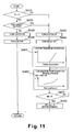
- Figure 10 is a flowchart presenting a third embodiment of the processing executed by the clutch control section shown in Figure 3;
- FIG 11 is a flowchart presenting a fourth embodiment of the processing executed by the clutch control section shown in Figure 3.
- a vehicle driving force control apparatus will now be explained in accordance with a first embodiment of the present invention.
- a four wheel drive vehicle is diagrammatically illustrated that is equipped with the vehicle driving force control apparatus in accordance with the present invention.
- the vehicle in accordance with this embodiment has left and right front wheels 1L and 1R that are driven by an internal combustion engine or main drive source 2, and left and right rear wheels 3L and 3R that are driven by an electric motor or subordinate drive source 4, which is preferably a direct current (DC) electric motor.
- DC direct current
- the output torque Te of the engine 2 is delivered to the left and right front wheels 1L and 1R after passing through a transmission 5a and a differential gear 5b.
- An endless drive belt 6 transfers power from the internal combustion engine 2 to an electric generator 7, which supplies electrical energy to the electric motor 4.
- a portion of the output torque Te of the engine 2 is delivered to the electric generator 7 by the endless drive belt 6.
- the generator 7 is rotated at a rotational speed Nh, which is obtained by multiplying the rotational speed Ne of the internal combustion engine 2 by the pulley ratio of the endless drive belt 6.
- the transmission 5a is provided with a shift or gear position detecting device 5c (gear ratio detecting device) configured to detect the current shift range or gear position of the transmission 5a.
- the shift position detecting device 5c sends a signal indicating the detected shift position to a 4WD controller 8.
- the transmission 5a executes gear shirting in response to a shift command from a transmission control unit (not shown in the drawings).
- the transmission control unit holds tables or the like containing information describing the shift schedule of the transmission based on the vehicle speed and the accelerator position. When it determines that the vehicle will pass through a shift point based on the current vehicle speed and accelerator position, the transmission control unit issues a shift command to the transmission.
- the generator 7 rotates at a rotational speed Nh that is equal to the product of the rotational speed Ne of the internal combustion engine 2 and the pulley ratio of the endless drive belt 6.
- the load (torque) placed on the internal combustion engine 2 by the generator 7 due to the field current Ith of the generator 7 is adjusted by the 4WD controller 8 to generate a voltage corresponding to the load torque.
- the voltage generated by the generator 7 can be supplied to the electric motor 4 through the electrical line 9.
- a junction box 10 is provided at an intermediate point in the electrical line 9 between the electric motor 4 and the generator 7.
- the drive shaft of the electric motor 4 can be connected to the rear wheels 3L and 3R via a reduction gear 11, a clutch 12 and a differential gear 13 in a conventional manner.
- a four-wheel drive vehicle in accordance with the present invention is configured such that the electric motor 4 is braked immediately after the clutch or other connecting device 12 disconnects the electric motor 4 from the subordinate drive wheels 3L and 3R, so that co-rotation of the electric motor 4 is prevented and the traveling speed region within which four-wheel drive can be used is expanded.
- the internal combustion engine 2 has an air intake passage 14 (e.g., the intake manifold) that includes a main throttle valve 15 and a subordinate throttle valve 16.
- the throttle opening of the main throttle valve 15 is adjusted/controlled in accordance with the amount of depression of the accelerator pedal 17, which also constitutes or functions as an accelerator position detecting device or sensor, or a throttle opening instructing device or sensor.
- the main throttle valve 15 is either mechanically linked to the depression amount of the accelerator pedal 17, or adjusted/controlled electrically by an engine controller 18 in accordance with the depression amount detection value from an accelerator sensor 29 that detects the depression amount of the accelerator pedal 17 or the degree of opening of the main throttle valve 15.
- the depression amount detection value from the accelerator sensor 29 is outputted as a control signal to the 4WD controller 8.
- the accelerator sensor 29 constitutes an acceleration or throttle detecting device or sensor.
- the phrase "accelerator position opening degree" as used herein refers to either a throttle opening amount of the main throttle valve 15 or a depression amount of the accelerator pedal 17 or similar accelerator device.
- the subordinate throttle valve 16 uses a stepper motor 19 as an actuator for adjusting its throttle opening. Specifically, the throttle opening of the subordinate throttle valve 16 is adjusted/controlled by the rotational angle of the stepper motor 19, which corresponds to the step count. The rotational angle of the stepper motor 19 is adjusted/controlled by a drive signal from the motor controller 20.
- the subordinate throttle valve 16 is provided with a throttle sensor 19a shown in Figure 2.
- the step count of the stepper motor 19 is feedback-controlled based on the throttle opening detection value detected by this throttle sensor 19a.
- the output torque of the internal combustion engine 2 can be controlled (reduced) independently of the driver's operation of the accelerator pedal 17 by adjusting the throttle opening of the subordinate throttle valve 16 so as to be smaller than the throttle opening of the main throttle valve 15.
- the vehicle driving force control apparatus is also equipped with an engine rotational speed sensor 21 that detects the rotational speed Ne of the internal combustion engine 2.
- the engine rotational speed sensor 21 outputs control signals that are indicative of the engine rotational speed Ne to both the engine controller 18 and the 4WD controller 8.
- the generator 7 is equipped with a voltage adjuster 22 (regulator) for adjusting the output voltage V.
- the 4WD controller 8 controls the generator load torque Th against the internal combustion engine 2 and the generated voltage V by adjusting the field current Ifh such as controlling a generator control command value c1 (duty ratio or field current value).
- the voltage regulator 22 controls the field current Ifh of the electric generator 7 and thereby controls the generator load torque Th imposed on the engine 2 by the generator 7 and the output voltage V generated by the generator 7.
- the voltage adjuster 22 receives the generator control command value c1 (duty ratio or field current value) from the 4WD controller 8 and adjusts the field current Ifh of the generator 7 to a value corresponding to the generator control command value c1.
- the voltage adjuster 22 is also configured and arranged to detect the output voltage V of the generator 7 and then output the detected voltage value to the 4WD controller 8. This arrangment constitutes the generator output voltage regulating section.
- the rotational speed Nh of the generator 7 can be computed based on the rotational speed Ne of the internal combustion engine 2 and the pulley ratio of the endless drive belt 6.
- a current sensor 23 is provided inside the junction box 10.
- the current sensor 23 detects the current value Ia of the electrical power supplied from the generator 7 to the electric motor 4 and outputs a detected armature current signal to the 4WD controller 8.
- the voltage value flowing through the electrical line 9 is detected by the 4WD controller 8 to produce a control signal indicative of the voltage across the electric motor 4.
- a relay 24 shuts offer connects the voltage (current) supplied to the electric motor 4 in accordance with a control command from the 4WD controller 8.
- the relay is configured such that when it is OFF the armature of the motor 4 is grounded, i.e., short circuited.
- a control command from the 4WD controller 8 controls the field current Ifin of the electric motor 4 to adjust the drive torque of the electric motor 4 to a target motor torque Tm.
- the adjustment of the field current Ifm by the 4WD controller 8 adjusts the drive torque Tm of the electric motor 4 to the target motor torque.
- a thermistor 25 measures the brush temperature of the electric motor 4 and produces a control signal indicative of the temperature of the electric motor 4 that is outputted to the 4WD controller 8.
- the vehicle driving force control apparatus is also equipped with a motor rotational speed device or sensor 26 that detects the rotational speed Nm of the drive shaft of the electric motor 4.
- the motor rotational speed sensor 26 outputs a control signal indicative of the detected rotational speed of the electric motor 4 to the 4WD controller 8.
- the motor rotational speed sensor 26 constitutes an input shaft rotational speed detector or sensor of the clutch 12.
- the clutch 12 is a wet friction clutch, such as a hydraulic clutch, and is configured to fasten (connect) and release (disconnect) in accordance with commands issued from the 4WD controller 8.
- a temperature sensor 40 is installed inside the clutch 12 and serves as an operating fluid temperature detecting device for detecting the temperature of the operating fluid inside the clutch 12.
- the wheels 1L, 1R, 3L and 3R are provided with wheel speed sensors 27FL, 27FR, 27RL, and 27RR, respectively.
- Each speed sensor 27FL, 27FR, 27RL, and 27RR outputs a pulse signal corresponding to the rotational speed of the respective wheel 1L, 1R, 3L and 3R to the 4WD controller 8.
- Each of the pulse signals serves as a wheel speed detection value indicative of the rotational speed of the respective wheel 1L, 1R, 3L and 3R, respectively.
- the wheel speed sensors 27RL and 27RR constitute an output shaft rotational speed detector or sensor of the clutch 12.
- the 4WD controller 8 is equipped with a generator control unit or section 8A, a relay control unit or section 8B, a motor control unit or section 8C, a clutch control unit or section 8D, a surplus torque computing unit or section 8E, a target torque limiting unit or section 8F, a surplus torque converting unit or section 8G and a four-wheel drive termination processing unit or section 8H.
- the 4WD controller 8 is a control unit that preferably includes a microcomputer with a 4WD control program that is operatively coupled to the internal combustion engine 2 and the electric motor 4 to control the torque applied to the left and right front wheels 1L and 1R by the internal combustion engine 2 and the torque applied to the left and right rear wheels 3L and 3R by an electric motor 4 as discussed below.
- the 4WD controller 8 can also include other conventional components such as an input interface circuit, an output interface circuit, and storage devices such as a ROM (Read Only Memory) device and a RAM (Random Access Memory) device.
- the memory circuit stores processing results and control programs.
- the RAM of the 4WD controller 8 stores statuses of operational flags and various control data for the control program.
- the ROM of the 4WD controller 8 stores various operations for the control program.
- the 4WD controller 8 is capable of selectively controlling any of the components of the driving force control apparatus in accordance with the control program. It will be apparent to those skilled in the art from this disclosure that the precise structure and algorithms for 4WD controller 8 can be any combination of hardware and software that will carry out the functions of the present invention.
- “means plus function” clauses as utilized in the claims should include any structure including, but not limited to, hardware and/or algorithm or software that can be utilized to carry out the function of the "means plus function” clause.
- the terms “device” and “section” as utilized in the claims should include any structure, i.e., hardware alone, software alone, or combination of hardware and software.
- the generator control section 8A uses the voltage regulator 22 to monitor the output voltage of the electric generator 7.
- the generator control section 8A is configured to output the generator control command value c1 of the generator 7 to adjust the field current Ifh in accordance with the generator command value c1.
- the generator control section 8A adjusts the field current Ifh of the electric generator 7 in such a manner as to obtain a prescribed output voltage V.
- the relay control section 8B controls (connection and disconnection) shutting off and connecting the electric power supplied from the generator 7 to the electric motor 4. In short, it functions to switch the motor 4 between a driven state and a non-driven state.
- the monitor control section 8C adjusts the torque of the electric motor 4 to the required prescribed value by adjusting the field current Ifm of the electric motor 4.
- the clutch control section 8D controls the state of the clutch 12 by outputting a clutch control command to the clutch 12.
- the clutch control section 8D operates the clutch 12 to an engaged (connected) state when the vehicle is determined to be in a four-wheel drive mode.
- the surplus torque computing section 8E, the target torque limiting section 8F, and the surplus torque converting section 8G execute their respective processing sequences in series (i.e., first 8E, then 8F, then 8G, back to 8E, etc.) in accordance with a prescribed sampling time, as shown in Figure 4.
- the surplus torque computing section 8E computes the slippage speed or velocity ⁇ V F , which is the magnitude of the acceleration slippage of the front wheels 1L and 1R.
- the average wheel speeds are computed based on the signals from the wheel speed sensors 27FL, 27FR, 27RL and 27RR.
- the surplus torque computing section 8E subtracts the average wheel speed of the rear wheels 3L and 3R (subordinate drive wheels) from the wheel speed of the front wheels 1L and 1R (main drive wheels) to find the slippage speed or velocity ⁇ V F .
- V Wf (V Wfl + V Wfr )/2
- V Wr (V Wrl + V Wrr )/2
- step S20 the surplus torque computing section 8E of the 4WD controller 8 determines whether or not the calculated slippage velocity ⁇ V F exceeds a prescribed value, such as zero.
- steps S10 and S20 constitute an acceleration slippage detection section that estimates if acceleration slippage is occurring in the front wheels 1L and 1R that is driven by the internal combustion engine 2. If slippage velocity ⁇ V F is determined to be zero or below, it is estimated that the front wheels 1 L and 1 R are not experiencing acceleration slippage and the 4WD controller 8 proceeds to step S30, where a target generator load torque Th is set to zero and the surplus torque computing section 8E of the 4WD controller 8 returns to the beginning of the control loop, and the 4WD controller 8 returns to the main program.
- step S20 if the slippage velocity ⁇ V F is determined to be larger than zero, then the surplus torque computing section 8E estimates that the front wheels 1L and 1R are experiencing acceleration slippage, and thus, control proceeds to step S40.
- step S40 the surplus torque computing section 8E computes the amount of torque T ⁇ V F that must be absorbed in order to suppress the acceleration slippage of the front wheels 1L and 1R.
- the absorption torque T ⁇ V F is an amount that is proportional to the acceleration slippage magnitude.
- step S50 a current load torque TG of the generator 7 is calculated by the surplus torque computing section 8E based on the Equation (5) below, and then the surplus torque computing section 8E proceeds to step S60.
- TG K2 V ⁇ Ia K3 ⁇ Nh where: V: voltage of the generator 7,
- step S60 the surplus torque computing section 8E computes surplus torque, i.e., the target generator load torque Th to be imposed by the electric generator 7.
- the target generator load torque Th is found based on the Equation (6) stated below, and the 4WD controller 8 returns to the beginning of the control loop.
- Th TG + T ⁇ V F
- the processing executed by the target torque (control) limiting section 8F will be explained based on Figure 6.
- the processing of the target generator load torque Th in the flow chart of Figure 6 constitutes a generator control section configured to control a generation load torque of the generator 7 to substantially correspond to an acceleration slippage magnitude of the drive wheel, when the acceleration slippage detection section estimates acceleration slippage occurring in the drive wheel.
- step S200 the target torque limiting section 8F of the 4WD controller 8 determines whether or not the target generator load torque Th is larger than the maximum load capacity HQ of the generator 7.
- the target torque limiting section 8F proceeds to the beginning of the control program to repeat the processing if the target torque limiting section 8F determines that target generator load torque Th is less than or equal to the maximum load capacity HQ of the generator 7. Conversely, the target torque limiting section 8F proceeds to step S210 if the 4WD controller 8 determines that the target generator load torque Th is larger than the maximum load capacity HQ of the generator 7.
- step S210 the target torque limiting section 8F calculates the excess torque ⁇ Tb, which is the amount by which the target generator load torque Th exceeds the maximum load torque HQ.
- step S220 the target torque limiting section 8F calculates the current engine torque Te.
- the current engine torque Te is computed based on the signals from the throttle sensor 19a and the engine rotational speed sensor 21 using an engine torque calculation map. Then, the 4WD controller 8 proceeds to step S230.
- step S230 the target torque limiting section 8F computes the engine torque upper limit value TeM.
- the engine controller 18 limits the engine toque Te in such a manner that the engine torque upper limit value TeM received from the target torque limiting section 8F becomes the upper limit value of the engine torque Te irregardless of operation of the accelerator pedal 17 by the driver.
- step S240 the target torque limiting section 8F substitutes the maximum load capacity HQ as the target generator load torque Th and the 4WD controller 8 returns to the main program.
- step S240 the target torque limiting section 8F substitutes the maximum load capacity HQ as the target generator load torque Th.
- the maximum load capacity HQ is assigned as the target generation load torque Th, and then the target torque limiting section 8F returns to the beginning of the control loop and the 4WD controller 8 returns to the main program.
- step S300 the surplus torque converting section 8G of the 4WD controller 8 determines if the target generator load torque Th is larger than 0. If the target generator load torque Th is determined to be larger than 0, then the program of the surplus torque converting section 8G proceeds to step S310 because the front wheels 1L and 1R are experiencing acceleration slippage.
- the surplus torque converting section 8G determines that the target generator load torque Th is less than or equal to 0, then the surplus torque converting section 8G returns to the beginning of the control loop because the front wheels 1L and 1R are not experiencing acceleration slippage or the traveling speed of the vehicle is such that the motor 4 will rotate at a rotational speed exceeding the maximum tolerable rotational speed of the motor 4 and the 4WD controller 8 returns to the main program without executing further steps of the surplus torque converting section 8G.
- the vehicle remains in a two-wheel drive mode.
- step S310 the surplus torque converting section 8G reads in the rotational speed Nm of the electric motor 4 detected by the motor rotational speed sensor 26.
- the target motor field current Ifmt corresponding to the rotational speed Nm of the electric motor 4 is calculated.
- the surplus torque converting section 8G sends the calculated target motor field current Ifmt to the motor control section 8C before the surplus torque converting section 8G proceeds to step S320.
- the target motor field current Ifmt is held at a fixed current value with respect to the rotational speed Nm of the electric motor 4 so long as the rotational speed Nm is less than a prescribed rotational speed.
- the field current Ifin of the electric motor 4 is reduced using a well-known weak field control method. More specifically, when the rotational speed of the electric motor 4 becomes high, the motor induced voltage E increases and the motor torque declines.
- the field current Ifmt of the electric motor 4 is reduced in order to reduce the induced voltage E and thereby increase the current flowing to the motor 4 in order to obtain a prescribed motor torque Tm.
- the prescribed torque Tm can be obtained because the induced voltage E is kept from increasing so that the motor torque is kept from declining. Since the motor field current Ifmt is controlled in two stages, i.e., one field current is used for rotational speeds below a prescribed rotational speed and another field current is used for rotational speeds equal to or above a prescribed rotational speed, the cost of the electronic circuitry can be reduced in comparison with a case in which the field current is controlled on a continuous basis.
- a motor torque correcting device that corrects the motor torque Tm on a continuous basis by adjusting the field current Ifint in accordance with the rotational speed Nm of the electric motor 4.
- the required motor torque Tm can be obtained because the induced voltage E of the electric motor 4 is kept from increasing so that the motor torque is kept from declining.
- This approach provides a smooth motor torque characteristic and thereby enables the vehicle to travel in a more stable manner than in the case of two-stage control and the motor to be driven in an efficient state at all times.
- step S320 the surplus torque converting section 8G calculates the induced voltage E of the motor 4 based on the target motor field current Ifin and the motor rotational speed Nm and proceeds to step S330.
- step S330 the surplus torque converting section 8G calculates the target motor torque Tm corresponding to the generator load torque Th computed by the surplus torque computing section 8E.
- step S340 the surplus torque converting section 8G calculates the target armature current Ia corresponding to the target motor torque Tm and the target motor field current Ifm and proceeds to step S350.
- the resistance R is the electrical resistance of the electrical wire 9 and the coil of the motor 4.
- the surplus torque converting section 8G then sends the calculated target voltage V of the electric generator 7 to the generator control section 8A and the 4WD controller 8 returns to the main program.
- surplus torque converting section 8G takes the control of the motor 4 into consideration when it calculates the target voltage V of the electric generator 7 required to obtain the target generator load torque Th, it is also acceptable to calculate target voltage value V directly from the target generator load torque Th.
- step S410 the clutch control section D determines if the target generator load torque Th is larger than 0. If the target generator load torque Th is larger than 0, then the clutch control section D determines that the front wheels 1L and 1R are slipping, i.e., the conditions for four-wheel drive are satisfied, and proceeds to step S420. Meanwhile, if the target generator load torque Th is 0 or below, the clutch control section D determines that the front wheels 1L and 1R are not slipping, i.e., the vehicle is in a two-wheel drive state, and proceeds to step S450.
- the timing at which the front wheels 1L and 1R cease to undergo acceleration slippage i.e., the timing at which the target generator load torque Th becomes 0, differs depending on such factors as the coefficient of friction ⁇ of the road surface and the accelerator position. More specifically, if the coefficient of friction ⁇ of the road surface is large, acceleration slippage of the front wheels 1L and 1R will only occur in a region of low vehicle traveling speeds. Similarly, it is also difficult for acceleration slippage to occur when the amount of accelerator pedal depression is small.
- the timing at which the vehicle shifts from four-wheel drive to two-wheel drive differs depending on the traveling state of the vehicle. More specifically, the traveling speed or motor rotational speed at which the vehicle shifts from four-wheel drive to two-wheel drive differs depending on the traveling state of the vehicle.
- step S420 the clutch control section 8D determines if the condition for disconnecting the clutch is satisfied. If so, the clutch control section D proceeds to step S450. If not, the clutch control section D proceeds to step S430.
- the determination as to whether or not the clutch disconnect condition is satisfied is made by determining if the current motor rotational speed Nm is less than a reference speed VC corresponding to such a vehicle speed value as 30 km/h. If the current motor rotational speed Nm is larger than the reference speed VC, then the clutch control section 8D determines that the clutch disconnect condition is satisfied. In this embodiment, the clutch disconnect condition is based not on the actual vehicle traveling speed but on whether the motor rotational speed Nm is larger than a reference speed VC.
- the motor rotational speed Nm is used to estimate the current traveling speed and the estimated speed is compared to a prescribed reference speed.
- the traveling speed corresponding to the reference speed VC is the reference traveling speed value and is obtained by multiplying the reference speed VC by the appropriate gear ratios. Needless to say, it is also acceptable to determine if the actual traveling speed is larger than a reference traveling speed value.
- step S430 the clutch control section 8D issues the clutch ON command and proceeds to step S440.
- step S440 the clutch control section 8D feeds the relay ON command to the relay control section 8B in order to put the vehicle into four-wheel drive and the 4WD controller 8 returns to the main program.
- step S450 the clutch control section issues the clutch OFF command and proceeds to step S460.
- step S460 the clutch control section 8D feeds the relay OFF command to the relay control section 8B in order to short circuit the motor armature 29 and proceeds to step S470.
- step S470 the clutch control section 8D determines if the motor rotational speed Nm is 0. If the motor rotational speed Nm is 0, the clutch control section 8D proceeds to step S480.
- step S480 the clutch control section 8D issues the motor braking command to the motor control section 8C, thereby braking the motor 4 by setting the motor field current Ifm to 0.
- step S480 constitutes a motor braking device.
- the 4WD controller then returns to the main program.
- the electric generator 7 When the torque transmitted to the front wheels 1L and 1R from the engine 2 exceeds the road surface reaction force torque limit, i.e., when the front wheels 1L and 1R (main drive wheels 1L and 1R) undergo acceleration slippage, due to the coefficient of friction ⁇ of the road surface being small or the accelerator pedal 17 being depressed deeply by the driver, the electric generator 7 is operated with a load torque Th corresponding to the magnitude of the acceleration slippage so that the drive torque transmitted to the front wheels 1L and 1R is adjusted to a value in the vicinity of the road surface reaction force torque limit of the front wheels 1L and 1R. As a result, the acceleration slippage of the front wheels 1L, 1R (main drive wheels 1L and 1R) is suppressed.
- the acceleration performance of the vehicle is improved because the surplus electric power generated by the electric generator 7 is used to drive the electric motor 4, which in turn drives the subordinate drive wheels, i.e., the rear wheels 3L and 3R (four-wheel drive).
- the electric motor 4 is driven using the surplus torque in excess of the road surface reaction torque limit of the main drive wheels 1L and 1R, the energy efficiency and fuel economy of the vehicle are also improved.
- this embodiment takes into consideration the fact that when traveling on a slippery road surface or the like, even if all the output torque Te of the internal combustion engine 2 is transferred to the front wheels 1L and 1R, not all of the torque will be used as driving force. The driving force that cannot be utilized efficiently by the front wheels 1L and 1R is outputted to the rear wheels 3L and 3R and the acceleration performance is improved.
- the clutch 12 is released and the vehicle is returned to two-wheel drive when the traveling speed of the vehicle reaches or exceeds a prescribed reference traveling speed value, i.e., when the motor rotational speed Nm reaches or exceeds a prescribed reference speed VC.
- the release of the clutch protects the motor 4 by preventing the motor 4 from reaching a rotational speed that exceeds its maximum tolerable rotational speed.
- the relay 24 is turned OFF and the armature of the motor 4 is short circuited, which causes a braking force to act on the motor 4.
- the capacity of the clutch has been limited because the larger the capacity of the clutch is, the larger the co-rotational torque acting on the motor will be.
- a clutch having a large capacity can be used because co-rotation of the motor can be prevented.
- FIG. 9 a vehicle driving force control apparatus in accordance with a second embodiment will now be explained.
- the configuration of the vehicle used in this second embodiment is the same as the configuration of the vehicle in the first embodiment (see Figure 1).
- the descriptions of the parts or steps of the second embodiment that are identical to the parts or steps of the first embodiment may be omitted for the sake of brevity.
- the rest of the configuration of the vehicle and the processing in the second embodiment are the same as the configuration of the first embodiment.
- FIG. 9 is an alternative to Figure 8, which shows the processing of the clutch control section 8D of the first embodiment.
- the processing of the second embodiment shown in Figure 9 is similar to the processing of the first embodiment shown in Figure 8 and many of the steps are identical. Steps that are the same as the third embodiment are indicated with the same reference numerals and explanation thereof is omitted for the sake of brevity. More specifically, Figure 9 differs from Figure 8 in that a new step S462 is inserted between steps S460 and S470.
- step S462 the clutch control section 8D calculates the motor field current (braking direction) Ifm based on the motor rotational speed Nm detected by the motor rotational speed sensor 26 at the time of clutch release and proceeds to step S470.
- the value of the motor field current Ifm is set in such a manner as to be smaller when the motor rotational speed Nm is small and larger when the motor rotational speed is large. In other words, the smaller the motor rotational speed Nm is, the smaller the braking force applied to the motor 4 will be.
- step S470 the clutch control section 8D returns to step S462 if the clutch control section 8D finds that the motor rotational speed is larger than 0.
- the field current of the motor is controlled in accordance with the rotational speed of the motor detected at the time of clutch release in such a manner that the braking force acting on the motor 4 is smaller if the motor rotational speed Nm is smaller and larger if the motor rotational speed Nm is larger.
- the second embodiment has the effects of avoiding the occurrence of noise and physical shock and enabling the motor to be stopped in a stable manner.
- FIG. 10 a vehicle driving force control apparatus in accordance with a third embodiment will now be explained.
- the configuration of the vehicle used in this third embodiment is the same as the configuration of the vehicle in the first embodiment (see Figure 1).
- the descriptions of the parts or steps of the third embodiment that are identical to the parts or steps of the prior embodiments may be omitted for the sake of brevity.
- the rest of the configuration of the vehicle and the processing in the third embodiment are the same as the configuration of the prior embodiments.
- FIG. 10 The flowchart shown in Figure 10 is an alternative to Figure 9, which shows the processing of the clutch control section 8D of the second embodiment.
- the processing of the third embodiment shown in Figure 10 is similar to the processing of the second embodiment shown in Figure 9 and many of the steps are identical. Steps that are the same as the third embodiment are indicated with the same reference numerals and explanation thereof is omitted for the sake of brevity. More specifically, Figure 10 differs from Figure 9 in that a new step S461 is inserted between steps S460 and S462 and step S462 is modified into step S462'.
- step S461 the clutch control section 8D calculates a field current proportional constant If0 based on the temperature of the clutch operating fluid detected by the temperature sensor 40 at the time of clutch release and proceeds to step S462'.
- the proportional constant If0 is calculated in such a manner that the smaller the temperature of the operating fluid is, larger the value of the proportional constant If0 is set.
- the motor field current Ifm set in step S462' is set for the purpose of braking the motor 4. Therefore, the motor field current Ifm is set such that the braking force applied to the motor 4 becomes larger as the proportional constant If0 becomes larger, i.e., as the temperature of the operating fluid becomes lower.
- step S462' the clutch control section 8D calculates a reference motor field current If based on the motor rotational speed Nm detected by the motor rotational speed sensor 26 at the time of clutch release and then calculates the motor field current (braking direction) Ifm by multiplying the reference motor field current If by proportional constant If0 calculated in step S461.
- the clutch control section 8D then proceeds to step S470.
- the value of the reference motor field current If is set in such a manner as to be smaller when the motor rotational speed Nm is small and larger when the motor rotational speed is large. In other words, the smaller the motor rotational speed Nm is, the smaller the braking force applied to the motor 4 will be.
- step S470 the clutch control section 8D returns to step S462' if the clutch control section 8D finds that the motor rotational speed is larger than 0.
- the field current of the motor is controlled in accordance with the temperature of the operating fluid detected at the time of clutch release (i.e., connecting device release) in such a manner that the braking force acting on the motor 4 is larger if the temperature of the clutch operating fluid is low and smaller if the temperature of the operating fluid is high.
- the third embodiment has the effect of reliably preventing rotation of the motor caused by co-rotational torque, which increases as the temperature of the operating fluid decreases and the viscosity of the operating fluid increases.
- FIG. 11 a vehicle driving force control apparatus in accordance with a fourth embodiment will now be explained.
- the configuration of the vehicle used in this fourth embodiment is the same as the configuration of the vehicle in the first embodiment (see Figure 1).
- the descriptions of the parts or steps of the fourth embodiment that are identical to the parts or steps of the prior embodiments may be omitted for the sake of brevity.
- the rest of the configuration of the vehicle and the processing in the fourth embodiment are the same as the configuration of the prior embodiments.
- FIG. 11 A fourth embodiment of a four-wheel drive vehicle in accordance with the present invention will now be explained using the flowchart shown in Figure 11.
- the flowchart shown in Figure 11 is an alternative to Figure 10, which shows the processing of the clutch control section 8D of the third embodiment.
- the processing of the fourth embodiment shown in Figure 11 is similar to the processing of the third embodiment shown in Figure 10 and many of the steps are identical. Steps that are the same as the third embodiment are indicated with the same reference numerals and explanation thereof is omitted for the sake of brevity. More specifically, Figure 11 differs from Figure 10 in step S461 has been modified into step S461' and step S462' has been modified into step S462".
- step S461' the clutch control section 8D calculates the acceleration of the vehicle at the time of clutch release by differentiating the rotational speed of the rear wheels 3L and3R (subordinate drive wheels) and then calculates a field current proportional constant Ifa based on the calculated vehicle acceleration.
- the value of the proportional constant Ifa is set in such a manner as to be larger when the vehicle acceleration is larger and smaller when the vehicle acceleration is smaller.
- the motor field current Ifm set in step S462" is set for the purpose of braking the motor 4. Therefore, the motor field current Ifin is set such that the braking force applied to the motor 4 becomes larger as the proportional constant Ifa becomes larger, i.e., as the vehicle acceleration becomes larger.
- step S462 similarly to step S461' of the previous embodiment, the clutch control section 8D calculates a reference motor field current If based on the motor rotational speed Nm detected by the motor rotational speed sensor 26 at the time of clutch release and then calculates the motor field current (braking direction) Ifm by multiplying the reference motor field current If by proportional constant Ifa calculated in step S461'.
- the clutch control section 8D then proceeds to step S470.
- the value of the reference motor field current If is set in such a manner as to be smaller when the motor rotational speed Nm is small and larger when the motor rotational speed is large. In other words, the smaller the motor rotational speed Nm is, the smaller the braking force applied to the motor 4 will be.
- step S470 the clutch control section 8D returns to step S462" if it finds that the motor rotational speed is larger than 0.
- the field current of the motor is controlled in accordance with vehicle acceleration at the time of clutch release in such a manner that the braking force applied to the motor 4 is larger if the vehicle acceleration is larger and smaller if the vehicle acceleration is smaller.
- the fourth embodiment has the effect of reliably preventing rotation of the motor caused by co-rotational torque, which increases as the vehicle acceleration increases.
- the present invention can also be applied to cases in which an alternating current motor is used.
- An inverter is generally used when an alternating current motor is used and the armature of the alternating current motor can be short circuited by, for example, turning ON the upper arms of all phases of the inverter or turning ON the lower arms of all phases of the inverter.
- the present invention is not limited to such an arrangement. It is also acceptable to drive the motor 4 with a separate battery. In such a case, the electric power generated by the electric generator 7 should be consumed by feeding it to a load device other than the motor 4.
Applications Claiming Priority (2)
| Application Number | Priority Date | Filing Date | Title |
|---|---|---|---|
| JP2003369452A JP4376589B2 (ja) | 2003-10-29 | 2003-10-29 | 四輪駆動車両 |
| JP2003369452 | 2003-10-29 |
Publications (2)
| Publication Number | Publication Date |
|---|---|
| EP1527928A1 true EP1527928A1 (fr) | 2005-05-04 |
| EP1527928B1 EP1527928B1 (fr) | 2007-12-19 |
Family
ID=34420182
Family Applications (1)
| Application Number | Title | Priority Date | Filing Date |
|---|---|---|---|
| EP04024866A Expired - Fee Related EP1527928B1 (fr) | 2003-10-29 | 2004-10-19 | Appareil de commande de la force motrice d'un véhicule hybride |
Country Status (6)
| Country | Link |
|---|---|
| US (1) | US7095196B2 (fr) |
| EP (1) | EP1527928B1 (fr) |
| JP (1) | JP4376589B2 (fr) |
| KR (1) | KR100695854B1 (fr) |
| CN (1) | CN1292932C (fr) |
| DE (1) | DE602004010767T2 (fr) |
Cited By (1)
| Publication number | Priority date | Publication date | Assignee | Title |
|---|---|---|---|---|
| FR2998528A1 (fr) * | 2012-11-26 | 2014-05-30 | Renault Sa | Systeme et procede de commande d'un vehicule automobile a machines electriques arrieres independantes |
Families Citing this family (29)
| Publication number | Priority date | Publication date | Assignee | Title |
|---|---|---|---|---|
| FR2887495B1 (fr) * | 2005-06-27 | 2007-09-28 | Peugeot Citroen Automobiles Sa | Procede pour piloter le couplage et le decouplage du premier moteur et du deuxieme moteur d'un groupe motopropulseur hybride parallele |
| JP2007245966A (ja) * | 2006-03-16 | 2007-09-27 | Nissan Motor Co Ltd | 車両用駆動制御装置 |
| US20070261902A1 (en) * | 2006-05-15 | 2007-11-15 | George Margoudakis | Electric motor vehicle |
| JP4776435B2 (ja) * | 2006-05-24 | 2011-09-21 | 本田技研工業株式会社 | 自走式作業機の走行駆動機構 |
| FR2918222B1 (fr) * | 2007-06-27 | 2010-06-04 | Valeo Equip Electr Moteur | Procede et une machine electrique de freinage d'un moteur thermique et vehicule lors de la phase d'arret de celui-ci. |
| CN101412378B (zh) * | 2007-12-11 | 2010-12-22 | 深圳市欧得亿泰智能技术开发有限公司 | 一种应用多个电装置驱动行驶的电动汽车 |
| US7699737B2 (en) * | 2008-02-05 | 2010-04-20 | Ford Global Technologies, Llc | Electric axle drive unit |
| JP4785888B2 (ja) * | 2008-04-07 | 2011-10-05 | 三菱電機株式会社 | 変速機の制御システム |
| JP4906825B2 (ja) | 2008-10-07 | 2012-03-28 | 三菱電機株式会社 | 車両挙動制御装置 |
| JP5615577B2 (ja) * | 2010-03-25 | 2014-10-29 | Gpm株式会社 | 電気自動車の挙動変化の把握支援装置、挙動変化の把握支援方法、車両点検装置及び車両点検方法 |
| JP5726369B2 (ja) * | 2012-03-07 | 2015-05-27 | 三菱電機株式会社 | 車両用発電電動機の電力変換装置および車両用発電電動機の制御方法 |
| JP5919143B2 (ja) * | 2012-08-31 | 2016-05-18 | 本田技研工業株式会社 | 駆動装置 |
| US10666168B2 (en) * | 2014-11-28 | 2020-05-26 | Koki Holdings Co., Ltd. | Electric tool |
| GB2545653A (en) * | 2015-12-18 | 2017-06-28 | Labinal Power Systems | Multi-stage synchronous generator |
| JP6670195B2 (ja) * | 2016-07-19 | 2020-03-18 | 本田技研工業株式会社 | 駆動装置 |
| JP6487879B2 (ja) * | 2016-07-19 | 2019-03-20 | ミネベアミツミ株式会社 | モータ制御回路、モータ駆動制御装置及びモータ駆動制御装置の制御方法 |
| CN106740260B (zh) * | 2016-11-28 | 2019-07-12 | 北京新能源汽车股份有限公司 | 一种绝缘栅极双极型晶体管igbt的控制方法及装置 |
| CN112983381A (zh) * | 2021-04-20 | 2021-06-18 | 烟台杰瑞石油装备技术有限公司 | 压裂设备及其控制方法、压裂系统 |
| CN110118127A (zh) | 2019-06-13 | 2019-08-13 | 烟台杰瑞石油装备技术有限公司 | 一种电驱压裂设备的供电半挂车 |
| CN214247597U (zh) | 2020-12-11 | 2021-09-21 | 烟台杰瑞石油装备技术有限公司 | 压裂设备 |
| US11680474B2 (en) | 2019-06-13 | 2023-06-20 | Yantai Jereh Petroleum Equipment & Technologies Co., Ltd. | Fracturing apparatus and control method thereof, fracturing system |
| US11746636B2 (en) * | 2019-10-30 | 2023-09-05 | Yantai Jereh Petroleum Equipment & Technologies Co., Ltd. | Fracturing apparatus and control method thereof, fracturing system |
| US11167644B2 (en) * | 2020-01-31 | 2021-11-09 | Lear Corporation | Method and system for notification of an active short circuit condition in an electric motor of a hybrid electric vehicle |
| US11462920B2 (en) | 2020-01-31 | 2022-10-04 | Lear Corporation | Method and system for producing an active short circuit condition in an electric motor of a hybrid electric vehicle |
| US11332029B2 (en) | 2020-01-31 | 2022-05-17 | Lear Corporation | Method and system for producing an active short circuit condition in an electric motor of a hybrid electric vehicle |
| US11662384B2 (en) | 2020-11-13 | 2023-05-30 | Yantai Jereh Petroleum Equipment & Technologies Co., Ltd. | Motor malfunction monitoring device, drive motor system and motor malfunction monitoring method |
| CA3157232A1 (fr) | 2020-11-24 | 2022-05-24 | Yantai Jereh Petroleum Equipment & Technologies Co., Ltd. | Systeme de fracturation |
| CN113315111B (zh) | 2021-04-26 | 2023-01-24 | 烟台杰瑞石油装备技术有限公司 | 一种供电方法及供电系统 |
| FR3134057B1 (fr) * | 2022-03-29 | 2024-02-16 | Psa Automobiles Sa | Procédé de pilotage d'un dispositif de couplage et de decouplage d'un moteur electrique de traction en fonction de criteres thermiques |
Citations (5)
| Publication number | Priority date | Publication date | Assignee | Title |
|---|---|---|---|---|
| EP1142743A2 (fr) * | 2000-04-07 | 2001-10-10 | Tochigi Fuji Sangyo Kabushiki Kaisha | Système de transmission de puissance et méthode pour son fonctionnement |
| EP1148275A1 (fr) * | 2000-04-19 | 2001-10-24 | Dana Italia S.p.A | Transmission pour véhicules industriels avec deux moteurs hydrostatiques commandés |
| EP1291220A1 (fr) * | 2001-09-10 | 2003-03-12 | Nissan Motor Company, Limited | Véhicule avec embrayage humide pour transmission de couple d'un moteur |
| JP2003111205A (ja) * | 2001-09-28 | 2003-04-11 | Honda Motor Co Ltd | ハイブリッド型車両の駆動力制御装置 |
| EP1326083A1 (fr) * | 2002-01-08 | 2003-07-09 | Nissan Motor Company, Limited | Système pour détecter l'usure de balai d'un moteur à courant continu |
Family Cites Families (13)
| Publication number | Priority date | Publication date | Assignee | Title |
|---|---|---|---|---|
| DE4133059A1 (de) * | 1991-10-04 | 1993-04-08 | Mannesmann Ag | Antriebsanordnung fuer ein kraftfahrzeug |
| US5713425A (en) * | 1996-01-16 | 1998-02-03 | Ford Global Technologies, Inc. | Parallel hybrid powertrain for an automotive vehicle |
| JP3618901B2 (ja) * | 1996-06-03 | 2005-02-09 | ビスコドライブジャパン株式会社 | 車両用推進装置 |
| JPH10213158A (ja) | 1996-11-27 | 1998-08-11 | Aichi Mach Ind Co Ltd | 電磁パウダークラッチ |
| JP2000343965A (ja) * | 1999-06-08 | 2000-12-12 | Nissan Diesel Motor Co Ltd | ハイブリッド車両 |
| DE60113216T2 (de) * | 2000-11-14 | 2006-02-23 | Nissan Motor Co., Ltd., Yokohama | Antriebskraftsteuerungsvorrichtung |
| JP3338428B2 (ja) | 2000-12-28 | 2002-10-28 | 株式会社日立製作所 | 車両駆動装置 |
| JP4215957B2 (ja) | 2001-02-19 | 2009-01-28 | 本田技研工業株式会社 | 前後輪駆動車両の制御装置 |
| US7163480B2 (en) * | 2001-05-03 | 2007-01-16 | Ford Global Technologies, Llc | Powertrain for a hybrid vehicle with all-wheel drive capability and method for controlling wheel slip |
| JP3594004B2 (ja) | 2001-09-05 | 2004-11-24 | 日産自動車株式会社 | 車両の発電駆動制御装置 |
| JP3895144B2 (ja) * | 2001-10-01 | 2007-03-22 | Gkn ドライブライン トルクテクノロジー株式会社 | 電動モータ用動力伝達装置 |
| JP2003326997A (ja) | 2002-05-16 | 2003-11-19 | Toyoda Mach Works Ltd | 前後輪駆動車用の駆動装置 |
| JP2004268901A (ja) * | 2003-02-18 | 2004-09-30 | Nissan Motor Co Ltd | 制動制御装置 |
-
2003
- 2003-10-29 JP JP2003369452A patent/JP4376589B2/ja not_active Expired - Fee Related
-
2004
- 2004-10-08 US US10/960,690 patent/US7095196B2/en active Active
- 2004-10-19 EP EP04024866A patent/EP1527928B1/fr not_active Expired - Fee Related
- 2004-10-19 DE DE602004010767T patent/DE602004010767T2/de active Active
- 2004-10-28 KR KR1020040086407A patent/KR100695854B1/ko not_active IP Right Cessation
- 2004-10-29 CN CNB2004100896909A patent/CN1292932C/zh not_active Expired - Fee Related
Patent Citations (5)
| Publication number | Priority date | Publication date | Assignee | Title |
|---|---|---|---|---|
| EP1142743A2 (fr) * | 2000-04-07 | 2001-10-10 | Tochigi Fuji Sangyo Kabushiki Kaisha | Système de transmission de puissance et méthode pour son fonctionnement |
| EP1148275A1 (fr) * | 2000-04-19 | 2001-10-24 | Dana Italia S.p.A | Transmission pour véhicules industriels avec deux moteurs hydrostatiques commandés |
| EP1291220A1 (fr) * | 2001-09-10 | 2003-03-12 | Nissan Motor Company, Limited | Véhicule avec embrayage humide pour transmission de couple d'un moteur |
| JP2003111205A (ja) * | 2001-09-28 | 2003-04-11 | Honda Motor Co Ltd | ハイブリッド型車両の駆動力制御装置 |
| EP1326083A1 (fr) * | 2002-01-08 | 2003-07-09 | Nissan Motor Company, Limited | Système pour détecter l'usure de balai d'un moteur à courant continu |
Non-Patent Citations (1)
| Title |
|---|
| PATENT ABSTRACTS OF JAPAN vol. 2003, no. 08 6 August 2003 (2003-08-06) * |
Cited By (3)
| Publication number | Priority date | Publication date | Assignee | Title |
|---|---|---|---|---|
| FR2998528A1 (fr) * | 2012-11-26 | 2014-05-30 | Renault Sa | Systeme et procede de commande d'un vehicule automobile a machines electriques arrieres independantes |
| WO2014080028A1 (fr) * | 2012-11-26 | 2014-05-30 | Renault S.A.S | Système et procédé de commande d'un véhicule automobile à machines électriques arrières indépendantes |
| US9630522B2 (en) | 2012-11-26 | 2017-04-25 | Renault S.A.S. | System and method for controlling a motor vehicle with independent rear electric machines |
Also Published As
| Publication number | Publication date |
|---|---|
| JP2005137099A (ja) | 2005-05-26 |
| EP1527928B1 (fr) | 2007-12-19 |
| CN1611382A (zh) | 2005-05-04 |
| KR20050040778A (ko) | 2005-05-03 |
| JP4376589B2 (ja) | 2009-12-02 |
| DE602004010767T2 (de) | 2008-07-31 |
| US7095196B2 (en) | 2006-08-22 |
| DE602004010767D1 (de) | 2008-01-31 |
| CN1292932C (zh) | 2007-01-03 |
| KR100695854B1 (ko) | 2007-03-20 |
| US20050093496A1 (en) | 2005-05-05 |
Similar Documents
| Publication | Publication Date | Title |
|---|---|---|
| EP1527928B1 (fr) | Appareil de commande de la force motrice d'un véhicule hybride | |
| EP1393953B1 (fr) | Dispositif de commande de la force d'entraînement d'un véhicule | |
| US7234553B2 (en) | Vehicle driving force control apparatus | |
| EP1535786B1 (fr) | Système d'anti-patinage à l'accélération pour véhicule hybride à quatre roues motrices | |
| EP1393959B1 (fr) | Dispositif de contrôle de la traction d'un véhicule | |
| US7004018B2 (en) | Vehicle driving force control apparatus | |
| US6930405B2 (en) | Vehicle control apparatus | |
| US6617704B2 (en) | Hybrid vehicle control apparatus | |
| US6953415B2 (en) | Vehicle control apparatus | |
| US6902511B2 (en) | Vehicle driving force control apparatus | |
| EP1714845A1 (fr) | Dispositif de commande d'un véhicule | |
| JP2005351165A (ja) | 車両の駆動力制御装置 | |
| US7204332B2 (en) | Vehicle driving force control apparatus | |
| JP4063252B2 (ja) | 車両の駆動力制御装置 | |
| US7182168B2 (en) | Vehicle drive force control apparatus | |
| EP1396377B1 (fr) | Commande de la force de propulsion d'un véhicule |
Legal Events
| Date | Code | Title | Description |
|---|---|---|---|
| PUAI | Public reference made under article 153(3) epc to a published international application that has entered the european phase |
Free format text: ORIGINAL CODE: 0009012 |
|
| 17P | Request for examination filed |
Effective date: 20041021 |
|
| AK | Designated contracting states |
Kind code of ref document: A1 Designated state(s): AT BE BG CH CY CZ DE DK EE ES FI FR GB GR HU IE IT LI LU MC NL PL PT RO SE SI SK TR |
|
| AX | Request for extension of the european patent |
Extension state: AL HR LT LV MK |
|
| AKX | Designation fees paid |
Designated state(s): DE FR GB |
|
| 17Q | First examination report despatched |
Effective date: 20061207 |
|
| GRAP | Despatch of communication of intention to grant a patent |
Free format text: ORIGINAL CODE: EPIDOSNIGR1 |
|
| GRAS | Grant fee paid |
Free format text: ORIGINAL CODE: EPIDOSNIGR3 |
|
| GRAA | (expected) grant |
Free format text: ORIGINAL CODE: 0009210 |
|
| AK | Designated contracting states |
Kind code of ref document: B1 Designated state(s): DE FR GB |
|
| REG | Reference to a national code |
Ref country code: GB Ref legal event code: FG4D |
|
| RIC1 | Information provided on ipc code assigned before grant |
Ipc: B60K 6/52 20071001ALI20071113BHEP Ipc: B60K 6/44 20071001ALI20071113BHEP Ipc: B60W 10/02 20060101ALI20071113BHEP Ipc: B60K 17/354 20060101ALI20071113BHEP Ipc: B60W 10/08 20060101AFI20071113BHEP Ipc: B60W 20/00 20060101ALI20071113BHEP |
|
| REF | Corresponds to: |
Ref document number: 602004010767 Country of ref document: DE Date of ref document: 20080131 Kind code of ref document: P |
|
| ET | Fr: translation filed | ||
| PLBE | No opposition filed within time limit |
Free format text: ORIGINAL CODE: 0009261 |
|
| STAA | Information on the status of an ep patent application or granted ep patent |
Free format text: STATUS: NO OPPOSITION FILED WITHIN TIME LIMIT |
|
| 26N | No opposition filed |
Effective date: 20080922 |
|
| REG | Reference to a national code |
Ref country code: FR Ref legal event code: PLFP Year of fee payment: 12 |
|
| PGFP | Annual fee paid to national office [announced via postgrant information from national office to epo] |
Ref country code: FR Payment date: 20150629 Year of fee payment: 12 |
|
| PGFP | Annual fee paid to national office [announced via postgrant information from national office to epo] |
Ref country code: GB Payment date: 20151014 Year of fee payment: 12 Ref country code: DE Payment date: 20151013 Year of fee payment: 12 |
|
| REG | Reference to a national code |
Ref country code: DE Ref legal event code: R119 Ref document number: 602004010767 Country of ref document: DE |
|
| GBPC | Gb: european patent ceased through non-payment of renewal fee |
Effective date: 20161019 |
|
| REG | Reference to a national code |
Ref country code: FR Ref legal event code: ST Effective date: 20170630 |
|
| PG25 | Lapsed in a contracting state [announced via postgrant information from national office to epo] |
Ref country code: GB Free format text: LAPSE BECAUSE OF NON-PAYMENT OF DUE FEES Effective date: 20161019 Ref country code: FR Free format text: LAPSE BECAUSE OF NON-PAYMENT OF DUE FEES Effective date: 20161102 Ref country code: DE Free format text: LAPSE BECAUSE OF NON-PAYMENT OF DUE FEES Effective date: 20170503 |