EP1527447B1 - Optische plattenlaufwerkvorrichtung, verfahren zur messung der neigung einer optischen platte und verfahren zur korrektur der neigung einer optischen platte - Google Patents
Optische plattenlaufwerkvorrichtung, verfahren zur messung der neigung einer optischen platte und verfahren zur korrektur der neigung einer optischen platte Download PDFInfo
- Publication number
- EP1527447B1 EP1527447B1 EP03784305A EP03784305A EP1527447B1 EP 1527447 B1 EP1527447 B1 EP 1527447B1 EP 03784305 A EP03784305 A EP 03784305A EP 03784305 A EP03784305 A EP 03784305A EP 1527447 B1 EP1527447 B1 EP 1527447B1
- Authority
- EP
- European Patent Office
- Prior art keywords
- objective lens
- pivot
- disc
- actuator means
- optical
- Prior art date
- Legal status (The legal status is an assumption and is not a legal conclusion. Google has not performed a legal analysis and makes no representation as to the accuracy of the status listed.)
- Expired - Lifetime
Links
- 230000003287 optical effect Effects 0.000 title claims abstract description 149
- 238000000034 method Methods 0.000 title claims description 46
- 230000015654 memory Effects 0.000 claims description 24
- 238000005259 measurement Methods 0.000 claims description 7
- 230000003213 activating effect Effects 0.000 claims 6
- CLOMYZFHNHFSIQ-UHFFFAOYSA-N clonixin Chemical compound CC1=C(Cl)C=CC=C1NC1=NC=CC=C1C(O)=O CLOMYZFHNHFSIQ-UHFFFAOYSA-N 0.000 abstract 3
- 238000006073 displacement reaction Methods 0.000 description 13
- 238000013461 design Methods 0.000 description 10
- 238000012937 correction Methods 0.000 description 8
- 230000001276 controlling effect Effects 0.000 description 7
- 230000008901 benefit Effects 0.000 description 2
- 238000005516 engineering process Methods 0.000 description 2
- 230000009471 action Effects 0.000 description 1
- 238000004364 calculation method Methods 0.000 description 1
- 230000008859 change Effects 0.000 description 1
- 230000008713 feedback mechanism Effects 0.000 description 1
- 230000006870 function Effects 0.000 description 1
- 238000004519 manufacturing process Methods 0.000 description 1
- 238000012986 modification Methods 0.000 description 1
- 230000004048 modification Effects 0.000 description 1
- 230000001681 protective effect Effects 0.000 description 1
- 230000001105 regulatory effect Effects 0.000 description 1
- 230000035945 sensitivity Effects 0.000 description 1
Images




Classifications
-
- G—PHYSICS
- G11—INFORMATION STORAGE
- G11B—INFORMATION STORAGE BASED ON RELATIVE MOVEMENT BETWEEN RECORD CARRIER AND TRANSDUCER
- G11B7/00—Recording or reproducing by optical means, e.g. recording using a thermal beam of optical radiation by modifying optical properties or the physical structure, reproducing using an optical beam at lower power by sensing optical properties; Record carriers therefor
- G11B7/08—Disposition or mounting of heads or light sources relatively to record carriers
- G11B7/09—Disposition or mounting of heads or light sources relatively to record carriers with provision for moving the light beam or focus plane for the purpose of maintaining alignment of the light beam relative to the record carrier during transducing operation, e.g. to compensate for surface irregularities of the latter or for track following
- G11B7/095—Disposition or mounting of heads or light sources relatively to record carriers with provision for moving the light beam or focus plane for the purpose of maintaining alignment of the light beam relative to the record carrier during transducing operation, e.g. to compensate for surface irregularities of the latter or for track following specially adapted for discs, e.g. for compensation of eccentricity or wobble
- G11B7/0956—Disposition or mounting of heads or light sources relatively to record carriers with provision for moving the light beam or focus plane for the purpose of maintaining alignment of the light beam relative to the record carrier during transducing operation, e.g. to compensate for surface irregularities of the latter or for track following specially adapted for discs, e.g. for compensation of eccentricity or wobble to compensate for tilt, skew, warp or inclination of the disc, i.e. maintain the optical axis at right angles to the disc
-
- G—PHYSICS
- G11—INFORMATION STORAGE
- G11B—INFORMATION STORAGE BASED ON RELATIVE MOVEMENT BETWEEN RECORD CARRIER AND TRANSDUCER
- G11B7/00—Recording or reproducing by optical means, e.g. recording using a thermal beam of optical radiation by modifying optical properties or the physical structure, reproducing using an optical beam at lower power by sensing optical properties; Record carriers therefor
- G11B7/08—Disposition or mounting of heads or light sources relatively to record carriers
- G11B7/09—Disposition or mounting of heads or light sources relatively to record carriers with provision for moving the light beam or focus plane for the purpose of maintaining alignment of the light beam relative to the record carrier during transducing operation, e.g. to compensate for surface irregularities of the latter or for track following
- G11B7/095—Disposition or mounting of heads or light sources relatively to record carriers with provision for moving the light beam or focus plane for the purpose of maintaining alignment of the light beam relative to the record carrier during transducing operation, e.g. to compensate for surface irregularities of the latter or for track following specially adapted for discs, e.g. for compensation of eccentricity or wobble
-
- G—PHYSICS
- G11—INFORMATION STORAGE
- G11B—INFORMATION STORAGE BASED ON RELATIVE MOVEMENT BETWEEN RECORD CARRIER AND TRANSDUCER
- G11B7/00—Recording or reproducing by optical means, e.g. recording using a thermal beam of optical radiation by modifying optical properties or the physical structure, reproducing using an optical beam at lower power by sensing optical properties; Record carriers therefor
- G11B7/08—Disposition or mounting of heads or light sources relatively to record carriers
- G11B7/09—Disposition or mounting of heads or light sources relatively to record carriers with provision for moving the light beam or focus plane for the purpose of maintaining alignment of the light beam relative to the record carrier during transducing operation, e.g. to compensate for surface irregularities of the latter or for track following
-
- G—PHYSICS
- G11—INFORMATION STORAGE
- G11B—INFORMATION STORAGE BASED ON RELATIVE MOVEMENT BETWEEN RECORD CARRIER AND TRANSDUCER
- G11B11/00—Recording on or reproducing from the same record carrier wherein for these two operations the methods are covered by different main groups of groups G11B3/00 - G11B7/00 or by different subgroups of group G11B9/00; Record carriers therefor
- G11B11/10—Recording on or reproducing from the same record carrier wherein for these two operations the methods are covered by different main groups of groups G11B3/00 - G11B7/00 or by different subgroups of group G11B9/00; Record carriers therefor using recording by magnetic means or other means for magnetisation or demagnetisation of a record carrier, e.g. light induced spin magnetisation; Demagnetisation by thermal or stress means in the presence or not of an orienting magnetic field
- G11B11/105—Recording on or reproducing from the same record carrier wherein for these two operations the methods are covered by different main groups of groups G11B3/00 - G11B7/00 or by different subgroups of group G11B9/00; Record carriers therefor using recording by magnetic means or other means for magnetisation or demagnetisation of a record carrier, e.g. light induced spin magnetisation; Demagnetisation by thermal or stress means in the presence or not of an orienting magnetic field using a beam of light or a magnetic field for recording by change of magnetisation and a beam of light for reproducing, i.e. magneto-optical, e.g. light-induced thermomagnetic recording, spin magnetisation recording, Kerr or Faraday effect reproducing
- G11B11/1055—Disposition or mounting of transducers relative to record carriers
- G11B11/10576—Disposition or mounting of transducers relative to record carriers with provision for moving the transducers for maintaining alignment or spacing relative to the carrier
Definitions
- the present invention relates in general to disc drive systems for storing information onto a disc-shaped storage medium or reading information from such disc-shaped storage medium, where the disc is rotated and a write/read head is moved radially with respect to the rotating disc.
- the present invention is applicable in the case of optical or magneto-optical disc systems.
- optical disc system will be used, but it is to be understood that this wording is intended to also cover magneto-optical disc systems.
- an optical storage disc comprises at least one track, either in the form of a continuous spiral or in the form of multiple concentric circles, of storage space where information may be stored.
- Optical discs may be read-only type, where information is recorded during manufacture, which data can only be read by a user.
- the optical storage disc may also be a writable type, where information may be stored by a user.
- an optical disc drive comprises, on the one hand, rotating means for receiving and rotating an optical disc, and on the other hand optical means for generating an optical beam, typically a laser beam, and for scanning the storage track with said laser beam. Since the technology of optical discs in general, the way in which information can be stored in an optical disc, and the way in which optical data can be read from an optical disc, is commonly known, it is not necessary here to describe this technology in more detail.
- an optical disc drive typically comprises a motor, which drives a hub engaging a central portion of the optical disc.
- the motor is implemented as a spindle motor, and the motor-driven hub may be arranged directly on the spindle axle of the motor.
- an optical disc drive For optically scanning the rotating disc, an optical disc drive comprises a light beam generator device (typically a laser diode), an objective lens for focussing the light beam in a focal spot on the disc, and an optical detector for receiving the reflected light reflected from the disc and for generating an electrical detector output signal.
- a light beam generator device typically a laser diode
- an objective lens for focussing the light beam in a focal spot on the disc
- an optical detector for receiving the reflected light reflected from the disc and for generating an electrical detector output signal.
- the objective lens is arranged axially displaceable, and the optical disc drive comprises focal actuator means for controlling the axial position of the objective lens.
- the focal spot should remain aligned with a track or should be capable of being positioned with respect to a new track.
- at least the objective lens is mounted radially displaceable, and the optical disc drive comprises radial actuator means for controlling the radial position of the objective lens.
- the optical disc drive comprises a sledge which is displaceably guided with respect to a disc drive frame, which frame also carries the spindle motor for rotating the disc.
- the travel course of the sledge is arranged substantially radially with respect to the disc, and the sledge can be displaced over a range substantially corresponding to the range from inner track radius to outer track radius.
- Said radial actuator means comprise a controllable sledge drive, for instance comprising a linear motor, a stepper motor, or a worm gear motor.
- the displacement of the sledge is intended for roughly positioning the optical lens.
- the optical disc drive comprises a lens platform which carries the objective lens and which is displaceably mounted with respect to said sledge.
- the displacement range of the platform with respect to the sledge is relatively small, but the positioning accuracy of the platform with respect to the sledge is larger than the positioning accuracy of the sledge with respect to the frame.
- the orientation of the objective lens is fixed, i.e. its axis is directed parallel to the rotation axis of the disc.
- the objective lens is pivotably mounted, such that its axis can make an angle with the rotation axis of the disc. Usually, this is implemented by making the platform pivotable with respect to the sledge.
- Tilt of the optical disc can be defined as a situation where the storage layer of the optical disc, at the location of the focal spot, is not exactly perpendicular to the rotation axis. Tilt can be caused by the optical disc being tilted as a whole, but is usually caused by the optical disc being warped, and as a consequence the amount of tilt depends on the location on disc.
- the optical beam is used to obtain the coordinates of two locations on opposite sites of the measuring location, located along the same radial line as the measuring location, i.e. having the same angular coordinate as the measuring location.
- the tilt angle at the measuring location is calculated from the relative axial distance and the relative radial distance between said two opposite locations.
- anchor locations are obtained by focusing the optical beam in such anchor locations.
- a general problem is associated with the fact that the objective lens is brought to a different radial position.
- the objective lens necessarily looses its original track position and must be radially displaced back to its original radial position before the apparatus can resume operation. It is a further objective of the present invention to overcome this disadvantage.
- the present invention is based on the understanding that the radial coordinate of the focal point of the optical beam is displaced radially when the objective lens is pivoted.
- the measuring method according to the present invention is performed by displacing the optical lens in axial direction and in pivot direction.
- the method is performed by first focusing the optical beam on the measuring location, moving the objective lens axially towards the optical disc, and pivoting the objective lens into two directions to obtain two focal locations.
- the optical beam is first focused at the measuring location, then the objective lens is pivoted into one direction followed by the objective lens being axially displaced towards the optical disc.
- a disadvantage of the known method is that it is restricted to finding a value for the tilt in a certain location. This value will be used as input in a device for correcting the tilt.
- the corrective action may consist in giving the optical lens a suitable pivot offset, i.e. pivoting the optical lens over a suitable pivot angle.
- One way of finding the appropriate pivot offset is to calculate a pivot angle on the basis of the measured tilt. Such calculation may, however, introduce errors, especially if circumstances like temperature change, and merely calculating a pivot angle does not offer any feedback mechanism which enables a check as to whether the calculated pivot angle is the optimal angle.
- the present invention also aims to provide a solution to this problem. More particularly, the present invention aims to provide a method for setting the pivot offset of the objective lens such that a tilt of the disc is corrected as good as possible, without the need to know the size of the tilt.
- the method for setting the pivot offset of the objective lens is performed by setting the pivot offset to a certain value, then focusing the optical beam on the measuring location, moving the objective lens axially towards the optical disc, and pivoting the objective lens into two directions to obtain two focal locations. If the two pivot angles are equal, the pivot offset is assumed to be correct. If not, the pivot offset is amended, and the above steps are repeated.
- the pivot offset of the objective lens is set to a certain value, the optical beam is focused at the measuring location, then the objective lens is pivoted into one direction followed by the objective lens being axially displaced towards the optical disc. Then, the objective lens is pivoted into the opposite direction over the same angle followed by the objective lens being axially displaced towards the optical disc. If the two axial displacements are equal, the pivot offset is assumed to be correct. If not, the pivot offset is amended, and the above steps are repeated.
- Figure 1 schematically illustrates an optical disc drive 1, suitable for storing information on or reading information from an optical disc 2.
- the disc drive apparatus 1 comprises an apparatus frame 3.
- the disc drive apparatus 1 comprises a motor 4 fixed to the frame 3, defining a rotation axis 5.
- the disc drive apparatus 1 may comprise a turntable or clamping hub 6, which in the case of a spindle motor 4 is mounted on the spindle axle 7 of the motor 4.
- the disc drive apparatus 1 further comprises a displaceable sledge 10, which is displaceably guided in the radial direction of the disc 2, i.e. in a direction substantially perpendicular to the rotation axis 5, by guiding means not shown for the sake of clarity.
- a radial sledge actuator designed for regulating the radial position of the sledge 10 with respect to the apparatus frame 3, is schematically indicated at 11. Since radial sledge actuators are known per se, while the present invention does not relate to the design and functioning of such radial sledge actuator, it is not necessary here to discuss the design and functioning of a radial sledge actuator in great detail.
- the rotation axis 5 will be taken as Z-axis.
- a rectangular coordinate system XYZ will be used, wherein the displacement direction of the sledge 10 will be taken as X-axis, whereas an Y-axis is defined perpendicular to the X-axis and the Z-axis.
- a polar coordinate system r, ⁇ will be used.
- the disc drive apparatus 1 further comprises a displaceable platform 20, which is displaceable in the radial direction of the disc 2 with respect to the sledge 10, and which is displaceably mounted with respect to the sledge 10 by mounting means not shown for the sake of clarity.
- the disc drive apparatus 1 further comprises an optical system 30 for scanning tracks (not shown) of the disc 2 by an optical beam.
- the optical system 30 comprises a light beam generating means 31, typically a laser such as a laser diode, which may be mounted with respect to the apparatus frame 3 or the sledge 10, and which is arranged to generate a light beam 32a which passes a beam splitter 33 and an objective lens 34 carried by the platform 20.
- the objective lens 34 focuses the light beam 32b on the disc 2.
- said platform 20 is also mounted axially displaceable (Z-direction) with respect to the sledge 10, while further the disc drive apparatus 1 also comprises an axial platform actuator 37 arranged for axially displacing the platform 20 with respect to the sledge 10. Since such axial platform actuators are known per se, while further the design and operation of such axial platform actuator is no subject of the present invention, it is not necessary here to discuss the design and operation of such axial platform actuator in great detail.
- Said objective lens is mounted pivotably with respect to the apparatus frame 3.
- said platform 20 being mounted pivotably with respect to the sledge 10 by mounting means not shown for the sake of clarity.
- the platform 20 can pivot about a pivot axis 40 which is directed parallel to the Y-axis, such that an optical axis 36 of the objective lens 34 is always located in the XZ-plane.
- the pivot axis 40 coincides with the optical centre of the objective lens 34.
- a pivot angle ( ⁇ ) will be defined as the angle between the Z-axis and the optical axis 36 of the objective lens 34. Since pivotably mounted platforms are known per se, while further the design and operation of such pivotably mounted platforms is no subject of the present invention, it is not necessary here to discuss the design and operation of such pivotably mounted platform in great detail.
- the disc drive apparatus 1 also comprises a pivot platform actuator 41 arranged for pivoting the platform 20 with respect to the sledge 10. Since such pivot platform actuators are known per se, while further the design and operation of such pivot platform actuator is no subject of the present invention, it is not necessary here to discuss the design and operation of such pivot platform actuator in great detail.
- the disc drive apparatus 1 further comprises a control unit 90 having a first output 90a connected to a control input of the motor 4, having a second output 90b coupled to a control input of the radial sledge actuator 11, having a third output 90c coupled to a control input of the radial platform actuator 21, having a fourth output 90d coupled to a control input of the axial platform actuator 37, and having a fifth output 90e coupled to a control input of the pivot platform actuator 41.
- a control unit 90 having a first output 90a connected to a control input of the motor 4, having a second output 90b coupled to a control input of the radial sledge actuator 11, having a third output 90c coupled to a control input of the radial platform actuator 21, having a fourth output 90d coupled to a control input of the axial platform actuator 37, and having a fifth output 90e coupled to a control input of the pivot platform actuator 41.
- the control unit 90 is designed to generate at its first output 90a a control signal S CM for controlling the motor 4, to generate at its second control output 90b a control signal S CS for controlling the sledge actuator 11, to generate at its third output 90c a control signal S CPr for controlling the radial platform actuator 21, to generate at its fourth output 90d a control signal S CPa for controlling the axial platform actuator 37, and to generate at its fifth output 90e a control signal S CPp for controlling the pivot platform actuator 41.
- the light beam 32b reflects from the disc 2 (reflected light beam 32c) and passes the objective lens 34 and the beam splitter 33 (beam 32d) to reach an optical detector 35 mounted with respect to the sledge 10.
- the control unit 90 further has a read signal input 90f for receiving a read signal S R from the optical detector 35.
- the read signal S R contains information relating to the fact whether or not the optical beam 32b is accurately focused on the optical disc 2. More particularly, a focal error signal (FES) can be derived from the read signal S R .
- FES focal error signal
- a point P is shown, having polar coordinates r and ⁇ .
- the normal to the surface in point P(r, ⁇ ) is exactly parallel to the Z-axis, but in the case where the disc 2 has a warped surface, as shown, the normal in point P(r, ⁇ ) makes an angle ⁇ (r, ⁇ ) with the Z-axis.
- This angle ⁇ (r, ⁇ ) will be taken as measure of the tilt in point P(r, ⁇ ).
- the tilt may vary over the surface of the disc, in other words the tilt ⁇ (r, ⁇ ) is a function of radial coordinate r and angular coordinate ⁇ . It is desirable to know ⁇ (r, ⁇ ) for an entire disc, or at least for that part of the disc which is to be accessed.
- Figure 2 schematically illustrates the basic principle underlying the measuring method proposed by the present invention.
- two points P1 and P2 of the disc 2 are shown on opposite sides of point P.
- these two points P1 and P2 have coordinates (r 1 , ⁇ ) and (r 2 , ⁇ ), respectively.
- the location P(r, ⁇ ) where the tilt is to be measured will be indicated as measuring location.
- Said two points P1 and P2 on opposite sides of the measuring location will be indicated as anchor points.
- the present invention is based on finding, with respect to a measuring location, two anchor points P1 and P2, and measuring the relative radial distance X2-X1 and the relative axial distance Z1-Z2 between these anchor points P1 and P2. As soon as this information is available, the tilt ⁇ at the measuring location can be calculated.
- Figure 3 illustrates a first implementation of the above-mentioned basic measuring principle.
- the objective lens 34 is brought to an initial focus position (indicated as 34 1 in the drawing) where the focal spot of the light beam 32 coincides with measuring location P(r, ⁇ ).
- the coordinates (x,y,z, ⁇ ) of the objective lens 34 in this initial focus position are defined as (x 0 ,0,z 0 , ⁇ 0 ) (since the objective lens can not move in the Y-direction, its Y-coordinate is always constant and may be taken as zero).
- the coordinates of the measuring location P(r, ⁇ ) are (x 0 ,0,z P ).
- the distance z P -z 0 corresponds to the focal distance f of the objective lens, which is taken to be constant.
- a second step the objective lens 34 is pivoted over a first angle ⁇ 1 towards smaller radius, to reach a position (34 2 ) having coordinates (x 0 ,0,z 0 , ⁇ 0 - ⁇ 1).
- Focus is regained by, in a third step, displacing the objective lens 34 axially until the control unit 90 finds that the optical beam 32 is again focused on the disc 2.
- this will require a certain axial displacement ⁇ z 1 , so that the objective lens 34 has reached a first focus measuring position (34 3 ) having coordinates (x 0 ,0,z 0 + ⁇ z 1 , ⁇ 0 - ⁇ 1 ).
- the control unit 90 will store the magnitude ⁇ z 1 of this axial displacement in a memory.
- the objective lens 34 is brought back to the initial focus position (x 0 ,0,z 0 , ⁇ 0 ).
- the objective lens 34 is pivoted over a second angle ⁇ 2 towards larger radius, to reach a position (34 4 ) having coordinates (x 0 ,0,z 0 , ⁇ 0 + ⁇ 2 ).
- the objective lens 34 is displaced axially until the control unit 90 finds that the optical beam 32 is again focused on the disc 2. Depending on the amount of tilt of the disc 2, this will require a certain axial displacement ⁇ z 2 , so that the objective lens 34 has reached a second focus measuring position (34 5 ) having coordinates (x 0 ,0,z 0 - ⁇ z 2 , ⁇ 0 + ⁇ 2 ).
- the control unit 90 will also store the magnitude ⁇ z 2 of this axial displacement in a memory.
- the first angle ⁇ 1 is equal to the second angle ⁇ 2 .
- tan ⁇ r ⁇ ⁇ ⁇ ⁇ z 1 + ⁇ ⁇ z 2 / 2 ⁇ f ⁇ ⁇ ⁇ ⁇ 1
- the fourth step may be omitted.
- fifth and sixth steps may be taken before the second and third steps, so as to first reach the anchor location P 2 at larger radius and then reach the anchor location P 1 at smaller radius.
- Figure 4 illustrates a second implementation of the above-mentioned basic measuring principle.
- the objective lens 34 is brought to an initial focus position (indicated as 34 1 in the drawing) where the focal spot of the light beam 32 coincides with measuring location P(r, ⁇ ).
- the coordinates (z,y,z, ⁇ ) of the objective lens 34 in this initial focus position are defined as (x 0 ,0,z 0 , ⁇ 0 ) (since the objective lens can not move in the Y-direction, its Y-coordinate is always constant and may be taken as zero).
- the coordinates of the measuring location P(r, ⁇ ) are (x 0 ,0,z P ).
- the distance z P -z 0 corresponds to the focal distance f of the objective lens, which is taken to be constant.
- the objective lens 34 is axially displaced over a distance ⁇ z towards the disc, to reach a position (34 2 ) having coordinates (x 0 ,0,z 0 + ⁇ z, ⁇ 0 ).
- the beam is now out of focus.
- the objective lens 34 is pivoted towards smaller radius until the control unit 90 finds that the optical beam 32 is again focused on the disc 2. Depending on the amount of tilt of the disc 2, this will require a certain first pivot angle ⁇ 1 , so that the objective lens 34 has reached a first focus measuring position (34 3 ) having coordinates (x 0 ,0,z 0 + ⁇ z, ⁇ 0 - ⁇ 1 ).
- the control unit 90 will store the magnitude ⁇ 1 of this first pivot angle in a memory.
- a fourth step the objective lens 34 is pivoted towards larger radius until the control unit 90 finds that the optical beam 32 is again focused on the disc 2 in a second focus measuring position (34 4 ) having coordinates (x 0 ,0,z 0 + ⁇ z, ⁇ 0 + ⁇ 2 ).
- the control unit 90 will also store the magnitude ⁇ 2 of this second pivot angle in a memory.
- the fourth step may be taken before the third step, so as to first reach the anchor location P 2 at larger radius and then reach the anchor location P 1 at smaller radius.
- the tilt ⁇ is expressed in terms of displacement ⁇ z and ⁇ .
- the control unit 90 does not have direct information regarding these parameters.
- control unit 90 has signals available representing said parameters ⁇ z and ⁇ .
- the displacement ⁇ z and ⁇ established by the respective actuators is proportional to the respective control signal generated by the control unit 90, especially if said displacements are small.
- the control unit 90 can calculate said displacements from its own control signals.
- the tilt ⁇ (r, ⁇ ) in one location P(r, ⁇ ) can be determined if the X-coordinates and the Z-coordinates of anchor points P1 and P2 are known. In principle, such measurements could be performed for one individual measuring point, keeping the optical disc 2 stationary. Normally, however, it is desired to determine the tilt ⁇ (r, ⁇ ) for a large number of values of r and ⁇ , i.e. over a large number of locations (or perhaps even over entire surface of the optical disc). This could be done by repeating the measuring method for each such location. However, this would be very impractical.
- the measuring method proposed by the present invention is preferably implemented by determining the tilt ⁇ (R i, ⁇ ) over 360° at a certain radius R i , i.e. for all points Pj at a certain radius R i , with a rotating disc.
- the objective lens is brought to an initial focus location at a certain radius R i , corresponding to a certain X-coordinate.
- the X-coordinates X 1j (R i - ⁇ r, ⁇ j ) and the Z-coordinates Z 1j (R i - ⁇ r, ⁇ j ) are determined and stored in a memory.
- the X-coordinates X 2j (R i + ⁇ r, ⁇ j ) and the Z-coordinates Z 2j (R i + ⁇ r, ⁇ j ) are determined and stored in a memory.
- the order may be reversed.
- the tilt ⁇ j (R i , ⁇ j ) can be calculated by combining the coordinates X 1j (R i - ⁇ r, ⁇ j ), X 2j (R i + ⁇ r, ⁇ j ), Z 1j (R i - ⁇ r, ⁇ j ), Z 2j (R i + ⁇ r, ⁇ j ) in the manner described earlier.
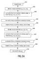
- the optical disc 2 is rotated (step 501) at a certain predetermined speed. Then, in a first step 502, the objective lens 34 is brought to an initial focus position (34 1 ) (x 0 ,0,z 0 , ⁇ 0 ) corresponding to measuring radius Ri.
- the pivot actuator 41 is activated such as to pivot the objective lens 34 over a first angle ⁇ 1 towards smaller radius, to reach a position (34 2 ) having coordinates (x 0 ,0,z 0 , ⁇ 0 - ⁇ 1 ).
- the focal actuator 37 is activated such as to regain focus (34 3 ) and to maintain focus.
- the focal control signal is sampled (step 505) over at least one revolution of the optical disc 2, and the sampled values are stored in a memory, in correlation to the angular position at which the focal control signal was sampled.
- a fourth step 506 the objective lens 34 is brought back to the initial focus position (x 0 ,0,z 0 , ⁇ 0 ).
- the pivot actuator 41 is activated such as to pivot the objective lens 34 over a second angle ⁇ 2 towards larger radius, to reach a position (34 4 ) having coordinates (x 0 ,0,z 0 , ⁇ 0 + ⁇ 2 ).
- the focal actuator 37 is activated such as to regain focus (34 5 ) and to maintain focus.
- the focal control signal is sampled (step 509) over at least one revolution of the optical disc 2, and the sampled values are stored in a memory, in correlation to the angular position at which the focal control signal was sampled.
- the tilt ⁇ j (Ri, ⁇ j ) can now be calculated (step 510) for different angular coordinates ⁇ j .
- the optical disc 2 is rotated (step 521) at a certain predetermined speed. Then, in a first step 522, the objective lens 34 is brought to an initial focus position (34 1 ) (x 0 ,0,z 0 , ⁇ 0 ) corresponding to measuring radius Ri.
- a second step 523 the focal actuator 37 is activated such as to axially displace the objective lens 34 over a distance ⁇ z towards the disc, to reach a position (34 2 ) having coordinates (x 0 ,0,z 0 + ⁇ z, ⁇ 0 ).
- the beam is now out of focus.
- the pivot actuator 41 is activated such as to pivot the objective lens 34 towards smaller radius, to regain focus (34 3 ), and to maintain focus.
- the pivot control signal is sampled (step 525) over at least one revolution of the optical disc 2, and the sampled values are stored in a memory, in correlation to the angular position at which the pivot control signal was sampled.
- a fourth step 526 the pivot actuator 41 is activated such as to pivot the objective lens 34 towards larger radius, to regain focus (34 4 ), and to maintain focus.
- the pivot control signal is sampled (step 527) over at least one revolution of the optical disc 2, and the sampled values are stored in a memory, in correlation to the angular position at which the pivot control signal was sampled.
- the tilt ⁇ j (Ri, ⁇ j ) can now be calculated (step 530) for different angular coordinates ⁇ j .
- the objective lens 34 is a symmetrical lens, and usually, in the case of a symmetrical lens, the tilt correction is optimal if the optical axis or main axis of the lens is directed substantially perpendicular to the reflecting layer of the disc, i.e. if the optical axis of the lens makes a pivot angle ⁇ equal to the tilt ⁇ of the disc 2.
- tilt correction can be achieved without needing to know the magnitude of the tilt.
- it is relatively easily possible to check whether the objective lens has an adequate tilt correction position without needing to know the magnitude of the tilt and even without needing to know the current magnitude of the pivot angle.
- the initial pivot angle in the initial focus position of the objective lens has been indicated as ⁇ 0 .
- the initial pivot angle ⁇ 0 will normally be zero, as illustrated in figures 3 and 4.
- the value of the initial pivot angle ⁇ 0 is not of great importance when calculating the tilt angle ⁇ in accordance with the method proposed by the invention and discussed above.
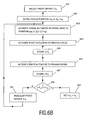
- the present invention also proposes a method for setting the objective lens 34 at an adequate pivot angle suitable for correcting tilt, as will be explained with reference to figures 6A-B. It is noted that the disc may be rotated, but may also be left stationary.
- a pivot offset ⁇ 0 is selected (step 601), and the objective lens 34 is brought to a focus condition (step 602). Then, as discussed with reference to figure 3, the objective lens 34 is pivoted (step 603) over a first angle ⁇ 1 and axially displaced (step 604) over a first axial distance ⁇ Z 1 such as to regain focus, and this first axial distance ⁇ Z 1 is stored (step 605) in a memory.
- the objective lens 34 is pivoted (step 607) over a second angle ⁇ 2 equal but opposite to the first angle ⁇ 1 , and axially displaced (step 608) over a second axial distance ⁇ Z 2 such as to regain focus, and this second axial distance ⁇ Z 2 is stored (step 609) in a memory.
- These two axial distances ⁇ Z 1 and ⁇ Z 2 are compared (step 610) to each other. If the pivot offset ⁇ 0 corresponds to the tilt, said two axial distances ⁇ Z 1 and ⁇ Z 2 will be equal to each other.
- the pivot offset ⁇ 0 is readjusted (step 611), and the above steps 602-609 are repeated until said two axial distances ⁇ Z 1 and ⁇ Z 2 are substantially equal to each other. Then, the current value of the pivot offset ⁇ 0 will be taken as operational pivot angle ⁇ C (step 612). It is noted that in this method it is not necessary to calculate ⁇ , and it is not necessary to know the focal distance f.
- a pivot offset ⁇ 0 is selected (step 621), and the objective lens is brought to a focus condition (step 622). Then, the objective lens 34 is axially displaced (step 623) over a certain axial distance ⁇ Z. The objective lens 34 is pivoted (step 624) over a first angle ⁇ 1 such as to regain focus, and this first angle ⁇ 1 is stored (step 625) in a memory.
- the objective lens 34 is pivoted (step 626) over a second angle ⁇ 2 opposite to the first angle ⁇ 1 , such as to regain focus, and this second angle ⁇ 2 is stored (step 627) in a memory.
- These two axial angles ⁇ 1 and ⁇ 2 are compared (step 630) to each other. If the pivot offset ⁇ 0 corresponds to the tilt, said two angles ⁇ 1 and ⁇ 2 will be equal to each other. If said two axial angles ⁇ 1 and ⁇ 2 are not, within certain limits, equal to each other, the pivot offset ⁇ 0 is readjusted (step 631), and the above steps 623-627 are repeated until said two angles ⁇ 1 and ⁇ 2 are substantially equal to each other. Then, the current value of the pivot offset ⁇ 0 will be taken as operational pivot angle ⁇ C (step 632). It is noted that in this method, too, it is not necessary to calculate ⁇ , and it is not necessary to know the focal distance f.
- the signal quality deteriorates.
- One of the possible causes may be that the disc has a tilt which does not correspond to the tilt correction setting of the objective lens. According to the present invention, this can be checked relatively easily.
- the current pivot angle of the objective lens is taken as initial pivot angle ⁇ 0 , and the above-discussed steps 603-609 or 623-627, respectively, are taken.
- the result of step 610 or 630, respectively determines whether the current pivot angle corresponds to an adequate tilt correction, or, conversely, whether the disc has obtained a tilt deviating from the current pivot angle. If necessary, the pivot angle is adjusted (step 611 or 631, respectively), and the pivot angle setting procedure discussed above is followed.
- the objective lens 34 is positioned for optimal tilt correction if the optical axis or main axis of the lens is directed substantially perpendicular to the reflecting layer of the disc, i.e. if the operational pivot angle ⁇ C is equal to the tilt ⁇ of the disc 2.
- the operational pivot angle ⁇ C should be different from the tilt ⁇ of the disc 2. Whether this will be the case or not, depends on the type of lens, and is known in advance. Further, it will be possible for the manufacturer of the disc drive apparatus to determine in advance an optimal relationship between the operational pivot angle ⁇ C and the tilt ⁇ of the disc 2. This relationship can be stored in a memory associated with the control unit 90, for instance in the form of a look-up table.
- control unit 90 may set the operational pivot angle ⁇ C of the objective lens 34 in accordance with the relationship stored in said memory.
- the initial pivot angle ⁇ 0 is set on the basis of the current pivot angle of the objective lens taking said relationship stored in said memory into account.
- the laser 31 and the detector 35 are mounted with respect to the frame 3.
Landscapes
- Optical Recording Or Reproduction (AREA)
- Length Measuring Devices By Optical Means (AREA)
- Testing Of Optical Devices Or Fibers (AREA)
Claims (21)
- In einem optischen Plattenlaufwerksgerät eines Typs, der Folgendes umfasst:- Drehmittel (4), die eine Drehachse (5) für eine optische Platte (2) definieren,- optische Abtastmittel (30) zum Abtasten einer optischen Platte mit einem Lichtbündel (32), wobei die optischen Abtastmittel (30) eine verlagerbare Objektivlinse (34) zum Fokussieren des Lichtbündels (32) auf der optischen Platte umfassen, wobei die Objektivlinse (34) in axialer Richtung (Z) verlagerbar ist und um eine Achse, die in tangentialer Richtung (Y) ausgerichtet ist, geschwenkt (ψ) werden kann,ein Verfahren zum Messen.einer Neigung (θ(r,ϕ)) an einer Messstelle (P(r,ϕ)) der optischen Platte, dadurch gekennzeichnet, dass das Verfahren die folgenden Schritte umfasst:In-Position-Bringen der Objektivlinse (34) an eine erste Brennpunktmessstelle durch Schwenken (ψ) und axiales Verlagern (Z) der Objektivlinse, um das Lichtbündel (32) in einem ersten Ankerpunkt (P1(r-Δr1,ϕ)) zu fokussieren, der im Wesentlichen die gleiche Winkelkoordinate ϕ wie die Messstelle (P(r,ϕ)) und einen kleinen radialen Abstand Δr 1 von der Messstelle (P(r,ϕ)) aufweist,In-Position-Bringen der Objektivlinse (34) an eine zweite Brennpunktmessstelle durch axiales Verlagern (Z) und Schwenken (ψ) der Objektivlinse, um das Lichtbündel (32) in einem zweiten Ankerpunkt (P2(r+Δr2,ϕ)) zu fokussieren, der im Wesentlichen die gleiche Winkelkoordinate ϕ wie die Messstelle (P(r,ϕ)) und einen kleinen radialen Abstand Δr2 von der Messstelle (P(r,ϕ)) aufweist,wobei der erste und der zweite Ankerpunkt an gegenüberliegenden Seiten der Messstelle (P(r,ϕ)) angeordnet sind,
wobei das Verfahren ferner den Schritt des Berechnens der Neigung (θ(r,ϕ)) an der Messstelle (P(r,ϕ)) aus den Koordinaten der beiden Brennpunktmessstellen der Objektivlinse (34) umfasst. - Verfahren nach Anspruch 1, das die folgenden Schritte umfasst:In-Position-Bringen der Objektivlinse (34) in eine anfängliche Brennpunktposition (341), um das Lichtbündel (32) an der Messstelle (P(r,ϕ)) zu fokussieren,Schwenken der Objektivlinse (34) um einen ersten Winkel (Δψ1) zu einem kleineren Radius in Bezug auf die anfängliche Brennpunktposition (341),axiales Verlagern der Objektivlinse (34) um einen ersten axialer. Abstand (Δz1), sodass das optische Strahlenbündel (32) wieder auf der Platte (2) fokussiert ist,Schwenken der Objektivlinse (34) um einen zweiten Winkel (Δψ2) zu einem größeren Radius in Bezug auf die anfängliche Brennpunktposition (341),axiales Verlagern der Objektivlinse (34) um einen zweiten axialen Abstand (Δz2), sodass das optische Strahlenbündel (32) wieder auf der Platte (2) fokussiert ist.
- Verfahren nach Anspruch 2, bei dem die Neigung (θ(r,ϕ)) der Messstelle (P(r,ϕ)) gemäß der Formel

berechnet wird. - Verfahren nach Anspruch 2 oder 3, bei dem der erste Winkel (Δψ1) gleich dem zweiten Winkel (Δψ2) ist.
- Verfahren nach Anspruch 1, das die folgenden Schritte umfasst:In-Position-Bringen der Objektivlinse (34) in eine anfängliche Brennpunktposition (341), um das Lichtbündel (32) an der Messstelle (P(r,ϕ)) zu fokussieren,axiales Verlagern der Objektivlinse (34) um einen axialen Abstand (Δz) zur Platte hin in Bezug auf die anfängliche Brennpunktposition (341),Schwenken der Objektivlinse (34) um einen ersten Winkel (Δψ1) zu einem kleineren Radius, sodass das optische Strahlenbündel (32) wieder auf der Platte (2) fokussiert ist,Schwenken der Objektivlinse (34) um einen zweiten Winkel (Δψ2) zu einem größeren Radius, sodass das optische Strahlenbündel (32) wieder auf der Platte (2) fokussiert ist.
- Verfahren nach Anspruch 5, bei dem die Neigung (θ(r,ϕ)) der Messstelle (P(r,ϕ)) gemäß der Formel

berechnet wird. - Verfahren nach einem der vorhergehenden Ansprüche, wobei die Messungen ausgeführt werden, während die Platte gedreht wird, sodass Messergebnisse für eine Vielzahl von Punkten erhalten werden, die auf einem ersten Radius liegen, und diese Messergebnisse in Korrelation zu der entsprechenden Winkelkoordinate in einem Speicher gespeichert werden, und sodass Messergebnisse für eine Vielzahl von Punkten erhalten werden, die auf einem zweiten Radius liegen, und diese Messergebnisse in Korrelation zu der entsprechenden Winkelkoordinate in einem Speicher gespeichert werden, und sodass die Neigung an mindestens einer Stelle, die auf einem Zwischenradius liegt und eine bestimmte Winkelkoordinate aufweist, aus den in den Speichern gespeicherten Messergebnissen berechnet wird.
- Optisches Plattenlaufwerksgerät, das Folgendes umfasst:Drehmittel (4), die eine Drehachse (5) für eine optische Platte (2) definieren,optische Abtastmittel (30) zum Abtasten einer optischen Platte mit einem Lichtbündel (32), wobei die optischen Abtastmittel (30) umfassen:wobei das Gerät ferner umfasst:- Lichtbündel-Erzeugungsmittel (31) zum Erzeugen eines Lichtbündels (32),- eine verlagerbare Objektivlinse (34) zum Fokussieren des Lichtbündels (32) auf der optischen Platte,radiale Aktuatormittel (11; 21), um die Objektivlinse (34) radial zu verlagern,axiale Aktuatormittel (37), um die Objektivlinse (34) axial zu verlagern,Schwenkaktuatormittel (41) zum Schwenken der Objektivlinse (34),Steuermittel (90) zum Steuern der radialen Aktuatormittel (11; 21), der axialen Aktuatormittel (37) und der Schwenkaktuatormittel (41),wobei die Steuermittel zum Messen der Neigung (θ(r,ϕ)) an einer Messstelle (P(r,ϕ)) einer optischen Platte ausgelegt sind, gekennzeichnet durch:- In-Position-Bringen der Objektivlinse (34) an eine erste Brennpunktmessstelle durch Schwenken (ψ) und axiales Verlagern (Z) der Objektivlinse, um das Lichtbündel (32) in einem ersten Ankerpunkt (P1(r-Δr1,ϕ)) zu fokussieren, der im Wesentlichen die gleiche Winkelkoordinate ϕ wie die Messstelle (P(r,ϕ)) und einen kleinen radialen Abstand Δr1 von der Messstelle (P(r,ϕ)) aufweist und- In-Position-Bringen der Objektivlinse (34) an eine zweite Brennpunktmessstelle durch Schwenken (ψ) und axiales Verlagern (Z) der Objektivlinse, um das Lichtbündel (32) in einem zweiten Ankerpunkt (P2(r+Δr2,ϕ)) zu fokussieren, der im Wesentlichen die gleiche Winkelkoordinate ϕ wie die Messstelle (P(r,ϕ)) und einen kleinen radialen Abstand Δr2 von der Messstelle (P(r,ϕ)) aufweist, wobei der erste und der zweite Ankerpunkt an gegenüberliegenden Seiten der Messstelle (P(r,ϕ)) angeordnet sind,- Berechnen der Neigung (θ(r,ϕ)) an der Messstelle (P(r,ϕ)) aus den Koordinaten der beiden Brennpunktmessstellen der Objektivlinse (34).
- Plattenlaufwerksgerät nach Anspruch 8, wobei die Steuermittel dafür ausgelegt sind, die folgenden Schritte auszuführen:- Aktivieren der radialen Aktuatormittel (11; 21) und der axialen Aktuatormittel (37), um die Objektivlinse (34) in eine anfängliche Brennpunktposition (341) zu bringen um das Lichtbündel (32) in der Messstelle (P(r,ϕ)) zu fokussieren,- Aktivieren der Schwenkaktuatormittel (41), um die Objektivlinse (34) um einen ersten Schwenkwinkel (Δψ1) zu einem kleineren Radius in Bezug auf die anfängliche Brennpunktposition (341) zu schwenken,- Aktivieren der axialen Aktuatormittel (37), um die Objektivlinse (34) um einen ersten axialen Abstand (Δz1) axial zu verlagern, sodass das optische Strahlenbündel (32) wieder auf der Platte (2) fokussiert ist,- Aktivieren der Schwenkaktuatormittel (41), um die Objektivlinse (34) um einen zweiten Schwenkwinkel (Δψ2) zu einem größeren Radius in Bezug auf die anfängliche Brennpunktposition (341) zu schwenken,- Aktivieren der axialen Aktuatormittel (37), um die Objektivlinse (34) um einen zweiten axialen Abstand (Δz2) axial zu verlagern, sodass das optische Strahlenbündel (32) wieder auf der Platte (2) fokussiert ist.
- Gerät nach Anspruch 9, bei dem die Steuermittel so ausgelegt sind, dass sie die Neigung (θ(r,ϕ)) an der Messstelle (P(r,ϕ)) gemäß der Formel

berechnen. - Gerät nach Anspruch 9 oder 10, wobei der erste Winkel (Δψ1) gleich dem zweiten Winkel (Δψ2) ist.
- Plattenlaufwerksgerät nach Anspruch 8, bei dem die Steuermitte 1 dafür ausgelegt sind, die folgenden Schritte auszuführen:- Aktivieren der radialen Aktuatormittel (11; 21) und der axialen Aktuatormittel (37), um die Objektivlinse (34) in eine anfängliche Brennpunktposition (341) zu bringen, um das Lichtbündel (32) in der Messstelle (P(r,ϕ)) zu fokussieren,- Aktivieren der axialen Aktuatormittel (37), um die Objektivlinse (34) um einen axialen Abstand (Δz) zur Platte hin axial zu verlagern,- Aktivieren der Schwenkaktuatormittel (41), um die Objektivlinse (34) um einen ersten Schwenkwinkel (Δψ1) zu einem kleineren Radius zu schwenken, sodass das optische Strahlenbündel (32) wieder auf der Platte (2) fokussiert ist,- Aktivieren der Schwenkaktuatormittel (41), um die Objektivlinse (34) um einen zweiten Schwenkwinkel (Δψ2) zu einem größeren Radius zu schwenken, sodass das das optische Strahlenbündel (32) wieder auf der Platte (2) fokussiert ist.
- Plattenlaufwerksgerät nach Anspruch 12, bei dem die Steuermittel so ausgelegt sind, dass sie die Neigung (θ(r,ϕ)) an der Messstelle (P(r,ϕ)) gemäß der Formel

berechnen. - Gerät nach einem der Ansprüche 8-13, bei dem die Steuereinheit dafür ausgelegt ist, die folgenden Schritte auszuführen:- Aktivieren der Drehmittel (4), um die Platte zu drehen,- Aktivieren der radialen Aktuatormittel (11; 21), um die Objektivlinse (34) in eine anfängliche radiale Position zu bringen,- Aktivieren der axialen Aktuatormittel (37), um die Objektivlinse (34) in eine anfängliche Brennpunktposition zu bringen,- Aktivieren des Schwenkaktuators (41), um die Objektivlinse (34) um einen ersten Winkel (Δψ1) zu einem kleineren Radius zu schwenken,- Aktivieren der axialen Aktuatormittel (37), um einen Brennpunktzustand zu erreichen und diesen aufrechtzuerhalten,- Abtasten des Brennpunktsteuersignals über wenigstens eine Umdrehung der optischen Platte (2),- Speichern der abgetasteten Werte in einem Speicher in Korrelation zu der Winkelposition, bei der das Brennpunktsteuersignal abgetastet wurde,- Aktivieren des Schwenkaktuators (41), um die Objektivlinse (34) um einen zweiten Winkel (Δψ2) zu einem größeren Radius zu schwenken,- Aktivieren der axialen Aktuatormittel (37), um einen Brennpunktzustand zu erreichen und diesen aufrechtzuerhalten,- Abtasten des Brennpunktsteuersignals über wenigstens eine Umdrehung der optischen Platte (2),- Speichern der abgetasteten Werte in einem Speicher in Korrelation zu der Winkelposition, bei der das Brennpunktsteuersignal abgetastet wurde,- Berechnen der Neigung an einer Stelle mit dem anfänglichen Radius unter Verwendung der gespeicherten Werte.
- Gerät nach einem der Ansprüche 8-13, bei dem die Steuereinheit dafür ausgelegt ist, die folgenden Schritte auszuführen:- Aktivieren der Drehmittel (4), um die Platte zu drehen,- Aktivieren der radialen Aktuatormittel (11; 21), um die Objektivlinse (34) in eine anfängliche radiale Position zu bringen,- Aktivieren der axialen Aktuatormittel (37), um die Objektivlinse (34) in eine anfängliche Brennpunktposition zu bringen,- Aktivieren der axialen Aktuatormittel (37), um die Objektivlinse (34) um einen Abstand (Δz) axial zur Platte hin zu verlagern,- Aktivieren des Schwenkaktuators (41) in einer ersten Richtung, um einen Brennpunktzustand zu erreichen und diesen aufrechtzuerhalten,- Abtasten des Schwenksteuersignals über wenigstens eine Umdrehung der optischen Platte (2),- Speichern der abgetasteten Werte in einem Speicher in Korrelation zu der Winkelposition, bei der das Schwenksteuersignal abgetastet wurde,- Aktivieren des Schwenkaktuators (41) in einer zweiten Richtung, um einen B-rennpunktzustand zu erreichen und diesen aufrechtzuerhalten,- Abtasten des Schwenksteuersignals über wenigstens eine Umdrehung der optischen Platte (2),- Speichern der abgetasteten Werte in einem Speicher in Korrelation zu der Winkelposition, bei der das Schwenksteuersignal abgetastet wurde,- Berechnen der Neigung an einer Stelle bei dem anfänglichen Radius unter Verwendung der gespeicherten Werte.
- In einem optischen Plattenlaufwerksgerät eines Typs, der Folgendes umfasst:- Drehmittel (4), die eine Drehachse (5) für eine optische Platte (2) definieren,- optische Abtastmittel (30) zum Abtasten einer optischen Platte mit einem Lichtbündel (32), wobei die optischen Abtastmittel (30) eine verlagerbare Objektivlinse (34) zum Fokussieren des Lichtbündels (32) auf der optischen Platte umfassen, wobei die Objektivlinse (34) in axialer Richtung (Z) verlagerbar ist und um eine Achse, die in tangentialer Richtung (Y) ausgerichtet ist, geschwenkt (ψ) werden kann,ein Verfahren zum Einstellen eines Betriebsschwenkwinkels (ψC) der Objektiv linse (34), dadurch gekennzeichnet, dass das Verfahren die folgenden Schritte umfasst:[a] Wählen eines anfänglichen Schwenk-Offsets (ψ0),[b] In-Position-Bringen der Objektivlinse (34) in eine anfängliche Brennpunktposition (x0, 0, z0, ψ0),[c] Schwenken der Objektivlinse (34) um einen ersten Winkel (Δψ1) zu einem kleineren Radius in Bezug auf die anfängliche Brennpunktposition (x0, 0, z0, ψ0) in eine Position (x0,0,z0,ψ0-Δψ1),[d] axiales Verlagern der Objektivlinse (34) um einen ersten axialen Abstand (Δz1), sodass das optische Strahlenbündel (32) wieder auf der Platte (2) fokussiert ist,[e] Schwenken der Objektivlinse (34) um einen zweiten Winkel (Δψ2) zu einem größeren Radius in Bezug auf die anfängliche Brennpunktposition (x0, 0, z0, ψ0) in eine Position (x0,0,z0,ψ0+Δψ2), wobei der zweite Winkel (Δψ2) gleich dem ersten Winkel (Δψ1) ist,[f] axiales Verlagern der Objektivlinse (34) um einen zweiten axialen Abstand (Δz2), sodass das optische Strahlenbündel (32) wieder auf der Platte (2) fokussiert ist,[g] Vergleichen des ersten axialen Abstands (Δz1) mit dem zweiten axialen Abstand (Δz2),[h1] Neueinstellen des Schwenk-Offsets (ψ0) und Wiederholen der Schritte [b]-[g],wenn der erste axiale Abstand (Δz1) innerhalb bestimmter Grenzen nicht im Wesentlichen gleich dem zweiten axialen Abstand (Δz2) ist,[h2] Einstellen des Betriebsschwenkwinkels (ψC) der Objektivlinse (34) auf der Grundlage des aktuellen Werts des Schwenk-Offsets (ψ0), wenn der erste axiale Abstand (Δz1) im Wesentlichen gleich dem zweiten axialen Abstand (Δz2) ist.
- In einem optischen Plattenlaufwerksgerät eines Typs, der Folgendes umfasst:- Drehmittel (4), die eine Drehachse (5) für eine optische Platte (2) definieren,- optische Abtastmittel (30) zum Abtasten einer optischen Platte mit einem Lichtbündel (32), wobei die optischen Abtastmittel (30) eine verlagerbare Objektivlinse (34) zum Fokussieren des Lichtbündels (32) auf der optischen Platte umfassen, wobei die Objektivlinse (34) in axialer Richtung (Z) verlagerbar ist und um eine Achse, die in tangentialer Richtung (Y) ausgerichtet ist, geschwenkt (ψ) werden kann,ein Verfahren zum Einstellen eines Betriebsschwenkwinkels (ψC) der Objektivlinse (34), dadurch gekennzeichnet, dass das Verfahren die folgenden Schritte umfasst:[a] Wählen eines anfänglichen Schwenk-Offsets (ψ0),[b] In-Position-Bringen der Objektivlinse (34) in eine anfängliche Brennpunktposition (x0, 0, z0, ψ0),[c] axiales Verlagern der Objektivlinse (34) um einen axialen Abstand (Δz) in Bezug auf die anfängliche Brennpunktposition (x0, 0, z0, ψ0) zur Platte hin,[d] Schwenken der Objektivlinse (34) um einen ersten Schwenkwinkel (Δψ1) zu einem kleineren Radius in eine Position (x0,0,z0,ψ0-Δψ1), sodass das optische Strahlenbünde1 (32) wieder auf der Platte fokussiert ist,[e] Schwenken der Objektivlinse (34) um einen zweiten Schwenkwinkel (Δψ2) zu einem größeren Radius in eine Position (x0,0,z0,ψ0+Δψ2), sodass das optische Strahlenbündel (32) wieder auf der Platte fokussiert ist,[f] Vergleichen des ersten Schwenkwinkels (Δψ1) mit dem zweiten Schwenkwinkel (Δψ2),[g1] Neueinstellen des Schwenk-Offsets (ψ0) und Wiederholen der Schritte [b]-[f],wenn der erste Schwenkwinkel (Δψ1) innerhalb bestimmter Grenzen nicht im Wesentlichen gleich dem zweiten Schwenkwinkel (Δψ2) ist,[g2] Einstellen des Betriebsschwenkwinkels (ψC) der Objektivlinse (34) auf der Grundlage des aktuellen Werts des Schwenk-Offsets (ψ0), wenn der erste Schwenkwinkel (Δψ1) im Wesentlichen gleich dem zweiten Schwenkwinkel (Δψ2) ist.
- Verfahren nach Anspruch 16 oder 17, bei dem der Betriebsschwenkwinkel (ψc) der Objektivlinse (34) so eingestellt wird, dass er gleich dem aktuellen Wert des Schwenk-Offsets (ψ0) ist.
- Verfahren nach Anspruch 16 oder 17, bei dem der Betriebsschwenkwinkel (ψc) der Objektivlinse (34) ferner auf der Grundlage einer optimalen Beziehung zwischen dem Betriebsschwenkwinkel (ψC) und der Neigung (θ) der Platte (2) eingestellt wird.
- Optisches Plattenlaufwerksgerät, das Folgendes umfasst:Drehmittel (4), die eine Drehachse (5) für eine optische Platte (2) definieren, optische Abtastmittel (30) zum Abtasten einer optischen Platte mit einem Lichtbündel (32),wobei die optischen Abtastmittel (30) umfassen:- Lichtbündel-Erzeugungsmittel (31) zum Erzeugen eines Lichtbündels (32),- eine verlagerbare Objektivlinse (34) zum Fokussieren des Lichtbündels (32) auf der optischen Platte,wobei das Gerät ferner umfasst:radiale Aktuatormittel (11; 21), um die Objektivlinse (34) radial zu verlagern,axiale Aktuatormittel (37), um die Objektivlinse (34) axial zu verlagern,Schwenkaktuatormittel (41) zum Schwenken der Objektivlinse (34),Steuermittel (90) zum Steuern der radialen Aktuatormittel (11; 21), der axialen Aktuatormittel (37) und der Schwenkaktuatormittel (41),wobei die Steuermittel zum Einstellen eines Betriebsschwenkwinkels (ψC) der Objektivlinse (34) ausgelegt sind, gekennzeichnet durch:[a] Wählen eines anfänglichen Schwenk-Offsets (ψ0),[b] Aktivieren der radialen Aktuatormittel (11; 21) und der axialen Aktuatormittel (37), um die Objektivlinse (34) in eine anfängliche Brennpunktposition (x0, 0, z0, ψ0) zu bringen,[c] Aktivieren der Schwenkaktuatormittel (41), um die Objektivlinse (34) um einen ersten Schwenkwinkel (Δψ1) zu einem kleineren Radius in eine Position (x0,0,z0,ψ0-Δψ1) zu schwenken,[d] Aktivieren der axialen Aktuatormittel (37), um die Objektivlinse (34) um einen ersten axialen Abstand (Δψ1) axial zu verlagern, sodass das optische Strahlenbündel (32) wieder auf der Platte (2) fokussiert ist,[e] Aktivieren der Schwenkaktuatormittel (41), um die Objektivlinse (34) um einen zweiten Schwenkwinkel (Δψ2) zu einem größeren Radius in eine Position (x0,0,z0,ψ0+Δψ2) zu schwenken, wobei der zweite Schwenkwinkel (Δψ2) dem ersten Schwenkwinkel (Δψ1) gleicht,[f] Aktivieren der axialen Aktuatormittel (37), um die Objektivlinse (34) um einen zweiten axialen Abstand (Δz2) axial zu verlagern, sodass das optische Strahlenbündel (32) wieder auf der Platte (2) fokussiert ist,[g] Vergleichen des ersten axialen Abstands (Δz1) mit dem zweiten axialen Abstand (Δz2),[h1] Neueinstellen des Schwenk-Offsets (ψ0) und Wiederholen der Schritte [b]-[g],wenn der erste axiale Abstand (Δz1) innerhalb bestimmter Grenzen nicht im Wesentlichen gleich dem zweiten axialen Abstand (Δz2) ist,[h2] Einstellen des Betriebsschwenkwinkels (ψC) der Objektivlinse (34) auf der Grundlage des aktuellen Werts des Schwenk-Offsets (ψ0), wenn der erste axiale Abstand (Δz1) im Wesentlichen gleich dem zweiten axialen Abstand (Δz2) ist,.
- Optisches Plattenlaufwerksgerät, das Folgendes umfasst:Drehmittel (4), die eine Drehachse (5) für eine optische Platte (2) definieren,optische Abtastmittel (30) zum Abtasten einer optischen Platte mit einem Lichtbündel (32), wobei die optischen Abtastmittel (30) umfassen:wobei das Gerät ferner umfasst:- Lichtbündel-Erzeugungsmittel (31) zum Erzeugen eines Lichtbündels (32),- eine verlagerbare Objektivlinse (34) zum Fokussieren des Lichtbündels (32) auf der optischen Platte,radiale Aktuatormittel (11; 21), um die Objektivlinse (34) radial zu verlagern,axiale Aktuatormittel (37), um die Objektivlinse (34) axial zu verlagern, Schwenkaktuatormittel (41) zum Schwenken der Objektivlinse (34),Steuermittel (90) zum Steuern der radialen Aktuatormittel (11; 21), der axialen Aktuatormittel (37) und der Schwenkaktuatormittel (41),wobei die Steuermittel zum Einstellen eines Betriebsschwenkwinkels (ψC) der Objektivlinse (34) ausgelegt sind, gekennzeichnet durch:[a] Wählen eines anfänglichen Schwenk-Offsets (ψ0),[b] Aktivieren der radialen Aktuatormittel (11; 21) und der axialen Aktuatormittel (37), um die Objektivlinse (34) in eine anfängliche Brennpunktposition (x0,0,z0,ψ0) zu bringen,[c] Aktivieren der axialen Aktuatormittel (37), um die Objektivlinse (34) um einen axialen Abstand (Δz) zu der Platte hin axial zu verlagern,[d] Aktivieren der Schwenkaktuatormittel (41), um die Objektivlinse (34) um einen ersten Schwenkwinkel (Δψ1) zu einem kleineren Radius in eine Position (x0,0,z0,ψ0-Δψ1) zu schwenken, sodass das Lichtbündel (32) wieder auf der Platte (2) fokussiert ist,[e] Aktivieren der Schwenkaktuatormittel (41), um die Objektivlinse (34) um einen zweiten Schwenkwinkel (Δψ2) zu einem größeren Radius in eine Position (x0,0,z0,ψ0+Δψ2) zu schwenken, sodass das Lichtbündel (32) wieder auf der Platte (2) fokussiert ist,[f] Vergleichen des ersten Schwenkwinkels (Δψ1) mit dem zweiten Schwenkwinkel (Δψ2),[g1] Neueinstellen des Schwenk-Offsets (ψ0) und Wiederholen der Schritte [b]-[f], wenn der erste Schwenkwinkel (Δψ1) innerhalb bestimmter Grenzen nicht i:n Wesentlichen gleich dem zweiten Schwenkwinkel (Δψ2) ist,[g2] Einstellen des Betriebsschwenkwinkels (ψC) der Objektivlinse (34) auf der Grundlage des aktuellen Werts des Schwenk-Offsets (ψ0), wenn der erste Schwenkwinkel (Δψ1) im Wesentlichen gleich dem zweiten Schwenkwinkel (Δψ2) ist.
Priority Applications (1)
| Application Number | Priority Date | Filing Date | Title |
|---|---|---|---|
| EP03784305A EP1527447B1 (de) | 2002-07-26 | 2003-06-26 | Optische plattenlaufwerkvorrichtung, verfahren zur messung der neigung einer optischen platte und verfahren zur korrektur der neigung einer optischen platte |
Applications Claiming Priority (4)
| Application Number | Priority Date | Filing Date | Title |
|---|---|---|---|
| EP02078075 | 2002-07-26 | ||
| EP02078075 | 2002-07-26 | ||
| EP03784305A EP1527447B1 (de) | 2002-07-26 | 2003-06-26 | Optische plattenlaufwerkvorrichtung, verfahren zur messung der neigung einer optischen platte und verfahren zur korrektur der neigung einer optischen platte |
| PCT/IB2003/002810 WO2004015700A1 (en) | 2002-07-26 | 2003-06-26 | Optical disc drive apparatus, method for measuring tilt of an optical disc, and method for correcting tilt of an optical disc |
Publications (2)
| Publication Number | Publication Date |
|---|---|
| EP1527447A1 EP1527447A1 (de) | 2005-05-04 |
| EP1527447B1 true EP1527447B1 (de) | 2007-06-06 |
Family
ID=31502762
Family Applications (1)
| Application Number | Title | Priority Date | Filing Date |
|---|---|---|---|
| EP03784305A Expired - Lifetime EP1527447B1 (de) | 2002-07-26 | 2003-06-26 | Optische plattenlaufwerkvorrichtung, verfahren zur messung der neigung einer optischen platte und verfahren zur korrektur der neigung einer optischen platte |
Country Status (10)
| Country | Link |
|---|---|
| US (1) | US7116619B2 (de) |
| EP (1) | EP1527447B1 (de) |
| JP (1) | JP4572114B2 (de) |
| KR (1) | KR101001173B1 (de) |
| CN (1) | CN1295693C (de) |
| AT (1) | ATE364222T1 (de) |
| AU (1) | AU2003242915A1 (de) |
| DE (1) | DE60314253T2 (de) |
| TW (1) | TWI333652B (de) |
| WO (1) | WO2004015700A1 (de) |
Families Citing this family (1)
| Publication number | Priority date | Publication date | Assignee | Title |
|---|---|---|---|---|
| US7570547B2 (en) * | 2005-08-22 | 2009-08-04 | Konica Minolta Opto, Inc. | Objective lens unit and optical pickup device |
Family Cites Families (17)
| Publication number | Priority date | Publication date | Assignee | Title |
|---|---|---|---|---|
| JP2605776B2 (ja) * | 1988-02-03 | 1997-04-30 | ヤマハ株式会社 | 光ディスク再生装置のチルトサーボ回路 |
| JPH0758559B2 (ja) * | 1988-09-02 | 1995-06-21 | シャープ株式会社 | 光ピックアップ装置 |
| JP3193105B2 (ja) * | 1992-02-29 | 2001-07-30 | 日本ビクター株式会社 | チルトエラー検出装置 |
| JP3529556B2 (ja) * | 1996-07-18 | 2004-05-24 | パイオニア株式会社 | 光ピックアップにおけるコマ収差補正方法及び装置 |
| US5881034A (en) * | 1996-08-20 | 1999-03-09 | Sony Corporation | Apparatus for driving objective lens |
| US6151174A (en) * | 1997-10-06 | 2000-11-21 | U.S. Philips Corporation | Device for optically scanning a record carrier |
| JP3443668B2 (ja) * | 1998-04-30 | 2003-09-08 | 富士通株式会社 | 収差補正方法及び収差補正装置 |
| KR100370187B1 (ko) * | 1998-08-05 | 2003-03-17 | 삼성전자 주식회사 | 광기록재생장치,이에적합한틸트보정방법,그리고기록제어방법 |
| JP2000357338A (ja) * | 1999-06-15 | 2000-12-26 | Sony Corp | 記録媒体駆動装置及びチルト検出方法 |
| JP2001236668A (ja) * | 1999-12-15 | 2001-08-31 | Samsung Electro Mech Co Ltd | チルト検出装置および方法 |
| US6788627B2 (en) * | 2000-06-27 | 2004-09-07 | Matsushita Electric Industrial Co., Ltd. | Optical recording and reproducing apparatus, tilt correction method, tilt correction program and medium |
| JP4400772B2 (ja) * | 2000-06-27 | 2010-01-20 | パナソニック株式会社 | 光記録・再生装置、チルト補正方法、プログラム、及び記録媒体 |
| JP3924440B2 (ja) * | 2001-05-17 | 2007-06-06 | 松下電器産業株式会社 | 光ディスク装置及びその制御方法 |
| JP2003248951A (ja) * | 2002-02-25 | 2003-09-05 | Funai Electric Co Ltd | 光ディスクのチルト制御装置 |
| EP1482491A4 (de) * | 2002-03-04 | 2008-02-20 | Matsushita Electric Industrial Co Ltd | Optischer kopf und diesen verwendende optische aufzeichnungs/wiedergabeeinrichtung und aberationskorrekturverfahren |
| JP2004062918A (ja) * | 2002-07-24 | 2004-02-26 | Pioneer Electronic Corp | チルトサーボ装置 |
| JP3975139B2 (ja) * | 2002-08-30 | 2007-09-12 | パイオニア株式会社 | チルト補正装置及びチルト補正方法 |
-
2003
- 2003-06-26 EP EP03784305A patent/EP1527447B1/de not_active Expired - Lifetime
- 2003-06-26 AU AU2003242915A patent/AU2003242915A1/en not_active Abandoned
- 2003-06-26 CN CNB038175517A patent/CN1295693C/zh not_active Expired - Fee Related
- 2003-06-26 DE DE60314253T patent/DE60314253T2/de not_active Expired - Lifetime
- 2003-06-26 JP JP2004527104A patent/JP4572114B2/ja not_active Expired - Fee Related
- 2003-06-26 US US10/521,867 patent/US7116619B2/en not_active Expired - Fee Related
- 2003-06-26 AT AT03784305T patent/ATE364222T1/de not_active IP Right Cessation
- 2003-06-26 WO PCT/IB2003/002810 patent/WO2004015700A1/en not_active Ceased
- 2003-06-26 KR KR1020057001269A patent/KR101001173B1/ko not_active Expired - Fee Related
- 2003-07-23 TW TW092120108A patent/TWI333652B/zh active
Non-Patent Citations (1)
| Title |
|---|
| None * |
Also Published As
| Publication number | Publication date |
|---|---|
| JP4572114B2 (ja) | 2010-10-27 |
| US7116619B2 (en) | 2006-10-03 |
| CN1672199A (zh) | 2005-09-21 |
| WO2004015700A1 (en) | 2004-02-19 |
| AU2003242915A1 (en) | 2004-02-25 |
| CN1295693C (zh) | 2007-01-17 |
| US20050265192A1 (en) | 2005-12-01 |
| DE60314253T2 (de) | 2008-01-31 |
| TWI333652B (en) | 2010-11-21 |
| AU2003242915A8 (en) | 2004-02-25 |
| JP2005534137A (ja) | 2005-11-10 |
| ATE364222T1 (de) | 2007-06-15 |
| KR20050019922A (ko) | 2005-03-03 |
| DE60314253D1 (de) | 2007-07-19 |
| EP1527447A1 (de) | 2005-05-04 |
| WO2004015700A8 (en) | 2005-03-17 |
| KR101001173B1 (ko) | 2010-12-15 |
| TW200415596A (en) | 2004-08-16 |
Similar Documents
| Publication | Publication Date | Title |
|---|---|---|
| CN101320574B (zh) | 光学系统的调整方法 | |
| KR20030084756A (ko) | 광디스크 장치, 빔 스폿의 이동 방법 및 광디스크 장치에있어서 실행 가능한 컴퓨터 프로그램 | |
| US8174946B2 (en) | Optical disk apparatus and method of controlling optical disk apparatus | |
| US7248543B2 (en) | Tilt servo system for correcting tilt angle of light beam in information read/write apparatus | |
| EP0820056B1 (de) | Verfahren und Vorrichtung zur Korrektur von Komaaberrationen in einem optischen Kopf | |
| US7116619B2 (en) | Optical disc drive apparatus, method for measuring tilt of an optical disc, and method for correcting tilt of an optical disc | |
| US6584065B1 (en) | Information recording medium apparatus for forming the same and information recording and reproducing systems | |
| JP3940927B2 (ja) | 光ディスク記録装置 | |
| EP1629469B1 (de) | Plattenlaufwerk und methode zum neigungsausgleich | |
| US20070211598A1 (en) | Optical disc apparatus | |
| US20070171802A1 (en) | Optical disc apparatus and method for adjusting the same | |
| US7751298B2 (en) | Optical disc apparatus | |
| US20080232207A1 (en) | Method and Device For Compensating Tilt of an Optical Data Carrier | |
| US20090086597A1 (en) | Optical disc apparatus and optical disc recording method | |
| JP2000090463A (ja) | 光学的記録再生装置 | |
| US20060215521A1 (en) | Disc drive apparatus | |
| JP2651238B2 (ja) | 光記憶装置 | |
| JPS63133324A (ja) | 光デイスク装置におけるフオ−カスサ−ボ制御系のオフセツト自動設定装置 | |
| JPH02246024A (ja) | 焦点位置の調整方法および焦点制御装置 | |
| JP2001034954A (ja) | 光学部品検査装置および傾き角補正値の校正方法 | |
| JPH0778889B2 (ja) | 光記憶装置とその制御方法 | |
| JPH0612690A (ja) | 光ディスク装置のフォーカスサーボ系のゲイン調整装置及びゲイン調整方法 | |
| JPH06187723A (ja) | 光薄型情報処理装置 | |
| JPH04178928A (ja) | 光ディスク装置 | |
| JPH0287334A (ja) | 光学的情報記録再生装置及び情報記録媒体 |
Legal Events
| Date | Code | Title | Description |
|---|---|---|---|
| PUAI | Public reference made under article 153(3) epc to a published international application that has entered the european phase |
Free format text: ORIGINAL CODE: 0009012 |
|
| 17P | Request for examination filed |
Effective date: 20050228 |
|
| AK | Designated contracting states |
Kind code of ref document: A1 Designated state(s): AT BE BG CH CY CZ DE DK EE ES FI FR GB GR HU IE IT LI LU MC NL PT RO SE SI SK TR |
|
| AX | Request for extension of the european patent |
Extension state: AL LT LV MK |
|
| DAX | Request for extension of the european patent (deleted) | ||
| GRAP | Despatch of communication of intention to grant a patent |
Free format text: ORIGINAL CODE: EPIDOSNIGR1 |
|
| GRAS | Grant fee paid |
Free format text: ORIGINAL CODE: EPIDOSNIGR3 |
|
| GRAA | (expected) grant |
Free format text: ORIGINAL CODE: 0009210 |
|
| AK | Designated contracting states |
Kind code of ref document: B1 Designated state(s): AT BE BG CH CY CZ DE DK EE ES FI FR GB GR HU IE IT LI LU MC NL PT RO SE SI SK TR |
|
| PG25 | Lapsed in a contracting state [announced via postgrant information from national office to epo] |
Ref country code: FI Free format text: LAPSE BECAUSE OF FAILURE TO SUBMIT A TRANSLATION OF THE DESCRIPTION OR TO PAY THE FEE WITHIN THE PRESCRIBED TIME-LIMIT Effective date: 20070606 Ref country code: LI Free format text: LAPSE BECAUSE OF FAILURE TO SUBMIT A TRANSLATION OF THE DESCRIPTION OR TO PAY THE FEE WITHIN THE PRESCRIBED TIME-LIMIT Effective date: 20070606 Ref country code: CH Free format text: LAPSE BECAUSE OF FAILURE TO SUBMIT A TRANSLATION OF THE DESCRIPTION OR TO PAY THE FEE WITHIN THE PRESCRIBED TIME-LIMIT Effective date: 20070606 |
|
| REG | Reference to a national code |
Ref country code: GB Ref legal event code: FG4D |
|
| REG | Reference to a national code |
Ref country code: CH Ref legal event code: EP |
|
| REG | Reference to a national code |
Ref country code: IE Ref legal event code: FG4D |
|
| REF | Corresponds to: |
Ref document number: 60314253 Country of ref document: DE Date of ref document: 20070719 Kind code of ref document: P |
|
| PG25 | Lapsed in a contracting state [announced via postgrant information from national office to epo] |
Ref country code: SE Free format text: LAPSE BECAUSE OF FAILURE TO SUBMIT A TRANSLATION OF THE DESCRIPTION OR TO PAY THE FEE WITHIN THE PRESCRIBED TIME-LIMIT Effective date: 20070906 |
|
| PG25 | Lapsed in a contracting state [announced via postgrant information from national office to epo] |
Ref country code: ES Free format text: LAPSE BECAUSE OF FAILURE TO SUBMIT A TRANSLATION OF THE DESCRIPTION OR TO PAY THE FEE WITHIN THE PRESCRIBED TIME-LIMIT Effective date: 20070917 |
|
| PG25 | Lapsed in a contracting state [announced via postgrant information from national office to epo] |
Ref country code: AT Free format text: LAPSE BECAUSE OF FAILURE TO SUBMIT A TRANSLATION OF THE DESCRIPTION OR TO PAY THE FEE WITHIN THE PRESCRIBED TIME-LIMIT Effective date: 20070606 |
|
| ET | Fr: translation filed | ||
| NLV1 | Nl: lapsed or annulled due to failure to fulfill the requirements of art. 29p and 29m of the patents act | ||
| REG | Reference to a national code |
Ref country code: CH Ref legal event code: PL |
|
| PG25 | Lapsed in a contracting state [announced via postgrant information from national office to epo] |
Ref country code: BE Free format text: LAPSE BECAUSE OF FAILURE TO SUBMIT A TRANSLATION OF THE DESCRIPTION OR TO PAY THE FEE WITHIN THE PRESCRIBED TIME-LIMIT Effective date: 20070606 |
|
| PG25 | Lapsed in a contracting state [announced via postgrant information from national office to epo] |
Ref country code: SI Free format text: LAPSE BECAUSE OF FAILURE TO SUBMIT A TRANSLATION OF THE DESCRIPTION OR TO PAY THE FEE WITHIN THE PRESCRIBED TIME-LIMIT Effective date: 20070606 Ref country code: BG Free format text: LAPSE BECAUSE OF FAILURE TO SUBMIT A TRANSLATION OF THE DESCRIPTION OR TO PAY THE FEE WITHIN THE PRESCRIBED TIME-LIMIT Effective date: 20070906 Ref country code: MC Free format text: LAPSE BECAUSE OF NON-PAYMENT OF DUE FEES Effective date: 20070630 Ref country code: PT Free format text: LAPSE BECAUSE OF FAILURE TO SUBMIT A TRANSLATION OF THE DESCRIPTION OR TO PAY THE FEE WITHIN THE PRESCRIBED TIME-LIMIT Effective date: 20071106 Ref country code: NL Free format text: LAPSE BECAUSE OF FAILURE TO SUBMIT A TRANSLATION OF THE DESCRIPTION OR TO PAY THE FEE WITHIN THE PRESCRIBED TIME-LIMIT Effective date: 20070606 Ref country code: CZ Free format text: LAPSE BECAUSE OF FAILURE TO SUBMIT A TRANSLATION OF THE DESCRIPTION OR TO PAY THE FEE WITHIN THE PRESCRIBED TIME-LIMIT Effective date: 20070606 |
|
| PG25 | Lapsed in a contracting state [announced via postgrant information from national office to epo] |
Ref country code: SK Free format text: LAPSE BECAUSE OF FAILURE TO SUBMIT A TRANSLATION OF THE DESCRIPTION OR TO PAY THE FEE WITHIN THE PRESCRIBED TIME-LIMIT Effective date: 20070606 |
|
| PLBE | No opposition filed within time limit |
Free format text: ORIGINAL CODE: 0009261 |
|
| STAA | Information on the status of an ep patent application or granted ep patent |
Free format text: STATUS: NO OPPOSITION FILED WITHIN TIME LIMIT |
|
| PG25 | Lapsed in a contracting state [announced via postgrant information from national office to epo] |
Ref country code: GR Free format text: LAPSE BECAUSE OF FAILURE TO SUBMIT A TRANSLATION OF THE DESCRIPTION OR TO PAY THE FEE WITHIN THE PRESCRIBED TIME-LIMIT Effective date: 20070907 Ref country code: DK Free format text: LAPSE BECAUSE OF FAILURE TO SUBMIT A TRANSLATION OF THE DESCRIPTION OR TO PAY THE FEE WITHIN THE PRESCRIBED TIME-LIMIT Effective date: 20070606 Ref country code: IT Free format text: LAPSE BECAUSE OF FAILURE TO SUBMIT A TRANSLATION OF THE DESCRIPTION OR TO PAY THE FEE WITHIN THE PRESCRIBED TIME-LIMIT Effective date: 20070606 |
|
| 26N | No opposition filed |
Effective date: 20080307 |
|
| PG25 | Lapsed in a contracting state [announced via postgrant information from national office to epo] |
Ref country code: RO Free format text: LAPSE BECAUSE OF FAILURE TO SUBMIT A TRANSLATION OF THE DESCRIPTION OR TO PAY THE FEE WITHIN THE PRESCRIBED TIME-LIMIT Effective date: 20070606 Ref country code: IE Free format text: LAPSE BECAUSE OF NON-PAYMENT OF DUE FEES Effective date: 20070626 |
|
| PG25 | Lapsed in a contracting state [announced via postgrant information from national office to epo] |
Ref country code: EE Free format text: LAPSE BECAUSE OF FAILURE TO SUBMIT A TRANSLATION OF THE DESCRIPTION OR TO PAY THE FEE WITHIN THE PRESCRIBED TIME-LIMIT Effective date: 20070606 |
|
| PG25 | Lapsed in a contracting state [announced via postgrant information from national office to epo] |
Ref country code: CY Free format text: LAPSE BECAUSE OF FAILURE TO SUBMIT A TRANSLATION OF THE DESCRIPTION OR TO PAY THE FEE WITHIN THE PRESCRIBED TIME-LIMIT Effective date: 20070606 |
|
| PG25 | Lapsed in a contracting state [announced via postgrant information from national office to epo] |
Ref country code: LU Free format text: LAPSE BECAUSE OF NON-PAYMENT OF DUE FEES Effective date: 20070626 |
|
| PG25 | Lapsed in a contracting state [announced via postgrant information from national office to epo] |
Ref country code: TR Free format text: LAPSE BECAUSE OF FAILURE TO SUBMIT A TRANSLATION OF THE DESCRIPTION OR TO PAY THE FEE WITHIN THE PRESCRIBED TIME-LIMIT Effective date: 20070606 Ref country code: HU Free format text: LAPSE BECAUSE OF FAILURE TO SUBMIT A TRANSLATION OF THE DESCRIPTION OR TO PAY THE FEE WITHIN THE PRESCRIBED TIME-LIMIT Effective date: 20071207 |
|
| PGFP | Annual fee paid to national office [announced via postgrant information from national office to epo] |
Ref country code: GB Payment date: 20110630 Year of fee payment: 9 |
|
| GBPC | Gb: european patent ceased through non-payment of renewal fee |
Effective date: 20120626 |
|
| PG25 | Lapsed in a contracting state [announced via postgrant information from national office to epo] |
Ref country code: GB Free format text: LAPSE BECAUSE OF NON-PAYMENT OF DUE FEES Effective date: 20120626 |
|
| REG | Reference to a national code |
Ref country code: DE Ref legal event code: R082 Ref document number: 60314253 Country of ref document: DE Representative=s name: VOLMER, GEORG, DIPL.-ING., DE |
|
| REG | Reference to a national code |
Ref country code: DE Ref legal event code: R082 Ref document number: 60314253 Country of ref document: DE Representative=s name: MEISSNER, BOLTE & PARTNER GBR, DE Effective date: 20140328 Ref country code: DE Ref legal event code: R082 Ref document number: 60314253 Country of ref document: DE Representative=s name: MEISSNER BOLTE PATENTANWAELTE RECHTSANWAELTE P, DE Effective date: 20140328 Ref country code: DE Ref legal event code: R082 Ref document number: 60314253 Country of ref document: DE Representative=s name: VOLMER, GEORG, DIPL.-ING., DE Effective date: 20140328 Ref country code: DE Ref legal event code: R081 Ref document number: 60314253 Country of ref document: DE Owner name: KONINKLIJKE PHILIPS N.V., NL Free format text: FORMER OWNER: KONINKLIJKE PHILIPS ELECTRONICS N.V., EINDHOVEN, NL Effective date: 20140328 |
|
| REG | Reference to a national code |
Ref country code: FR Ref legal event code: CD Owner name: KONINKLIJKE PHILIPS N.V., NL Effective date: 20141126 Ref country code: FR Ref legal event code: CA Effective date: 20141126 |
|
| REG | Reference to a national code |
Ref country code: FR Ref legal event code: PLFP Year of fee payment: 13 |
|
| PGFP | Annual fee paid to national office [announced via postgrant information from national office to epo] |
Ref country code: DE Payment date: 20150831 Year of fee payment: 13 |
|
| PGFP | Annual fee paid to national office [announced via postgrant information from national office to epo] |
Ref country code: FR Payment date: 20150630 Year of fee payment: 13 |
|
| REG | Reference to a national code |
Ref country code: DE Ref legal event code: R082 Ref document number: 60314253 Country of ref document: DE Representative=s name: MEISSNER, BOLTE & PARTNER GBR, DE Ref country code: DE Ref legal event code: R082 Ref document number: 60314253 Country of ref document: DE Representative=s name: MEISSNER BOLTE PATENTANWAELTE RECHTSANWAELTE P, DE |
|
| REG | Reference to a national code |
Ref country code: DE Ref legal event code: R119 Ref document number: 60314253 Country of ref document: DE |
|
| REG | Reference to a national code |
Ref country code: FR Ref legal event code: ST Effective date: 20170228 |
|
| PG25 | Lapsed in a contracting state [announced via postgrant information from national office to epo] |
Ref country code: DE Free format text: LAPSE BECAUSE OF NON-PAYMENT OF DUE FEES Effective date: 20170103 Ref country code: FR Free format text: LAPSE BECAUSE OF NON-PAYMENT OF DUE FEES Effective date: 20160630 |