EP1526586A2 - Supraleitender Draht, Herstellungsvefahren und daraus hergestellte Artikel - Google Patents
Supraleitender Draht, Herstellungsvefahren und daraus hergestellte Artikel Download PDFInfo
- Publication number
- EP1526586A2 EP1526586A2 EP04256454A EP04256454A EP1526586A2 EP 1526586 A2 EP1526586 A2 EP 1526586A2 EP 04256454 A EP04256454 A EP 04256454A EP 04256454 A EP04256454 A EP 04256454A EP 1526586 A2 EP1526586 A2 EP 1526586A2
- Authority
- EP
- European Patent Office
- Prior art keywords
- superconducting
- magnesium
- wire
- boron
- superconducting wire
- Prior art date
- Legal status (The legal status is an assumption and is not a legal conclusion. Google has not performed a legal analysis and makes no representation as to the accuracy of the status listed.)
- Granted
Links
Images

Classifications
-
- H—ELECTRICITY
- H10—SEMICONDUCTOR DEVICES; ELECTRIC SOLID-STATE DEVICES NOT OTHERWISE PROVIDED FOR
- H10N—ELECTRIC SOLID-STATE DEVICES NOT OTHERWISE PROVIDED FOR
- H10N60/00—Superconducting devices
- H10N60/01—Manufacture or treatment
- H10N60/0856—Manufacture or treatment of devices comprising metal borides, e.g. MgB2
-
- Y—GENERAL TAGGING OF NEW TECHNOLOGICAL DEVELOPMENTS; GENERAL TAGGING OF CROSS-SECTIONAL TECHNOLOGIES SPANNING OVER SEVERAL SECTIONS OF THE IPC; TECHNICAL SUBJECTS COVERED BY FORMER USPC CROSS-REFERENCE ART COLLECTIONS [XRACs] AND DIGESTS
- Y10—TECHNICAL SUBJECTS COVERED BY FORMER USPC
- Y10S—TECHNICAL SUBJECTS COVERED BY FORMER USPC CROSS-REFERENCE ART COLLECTIONS [XRACs] AND DIGESTS
- Y10S505/00—Superconductor technology: apparatus, material, process
- Y10S505/70—High TC, above 30 k, superconducting device, article, or structured stock
- Y10S505/704—Wire, fiber, or cable
Definitions
- a method of manufacturing a wire comprising filling a hole in a metal tube with magnesium; sealing the ends of the tube; deforming the tube to increase it length; and contacting the tube with boron to react the magnesium with the boron to form superconducting magnesium diboride.
- a method for making a superconducting wire comprising contacting a boron filament, boron tape, or a combination comprising an assembly of boron filaments or tapes with molten magnesium to form a magnesium diboride wire.
- a method of manufacturing a wire comprising extruding a preform comprising a metal matrix and at least one filament; wherein the filament comprises a superconducting composition comprising magnesium diboride to form an extruded preform; and wire drawing or swaging the extruded preform to form the superconducting wire.
- Described herein are methods for manufacturing large lengths of superconducting wires, wherein the wires comprise filaments of magnesium diboride.
- the filaments are generally welded together to from wires having lengths of greater than or equal to about 350,000 feet, preferably greater than or equal to about 500,000 feet, and more preferably greater than or equal to about 1,000,000 feet.
- Preferred methods of joining are electron beam welding and laser beam welding.
- the wires may be advantageously formed into other similar electrically conducting structures, such as flattened tapes and wound multi-wire cables.
- Applications for superconducting wires are found in electromagnetic devices such as superconducting magnets, motors, transformers, and generators. Such electromagnetic devices may in turn be incorporated into larger systems, such as, for example, a magnetic resonance imaging system.
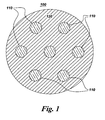
- FIG 1 is a schematic representation of a cross-sectional view of one exemplary embodiment of the superconducting wire 100.
- Superconducting wire 100 includes at least one filament 110 having a superconducting composition. Although seven such filaments 110 are represented in the Figure 1, there is no limit to the number of filaments 110 contained within superconducting wire 100.
- at least a portion of the filaments are encapsulated in an optional metal matrix 120, which facilitates the establishment of continuous length of superconducting filament.
- the superconducting wire 100 does not have a metal matrix and consists essentially of one or more filaments 110 comprising a superconducting composition.
- the filament 110 comprises a superconducting composition.
- the superconducting composition comprises primarily magnesium diboride (MgB 2 ), which has a superconducting transition temperature (T c ) of approximately 39 K.
- MgB 2 magnesium diboride
- T c superconducting transition temperature
- Magnesium diboride has a supercritical conductivity temperature T c that is higher by almost a factor of two of any known non-oxide and non-C 60 -based compound.
- the magnesium diboride superconducting composition preferably contains a first superconducting phase of magnesium and boron, but may optionally contain other dopants such as a metallic phase support.
- the first superconducting phase is magnesium diboride.
- the first superconducting phase can be a solid solution between magnesium diboride and another component, such as titanium boride and/or titanium diboride.
- the superconducting compositions can optionally comprise a second superconducting phase that has the same or a related crystallographic structure as the magnesium diboride and having comparable superconducting properties.
- the dopants in addition to providing metallic phase support may be incorporated for purposes of changing lattice configurations or spacing and/or improving superconducting properties.
- useful dopants that may be added include copper, gold, silver, magnesium, zinc, lead, cadmium, tin, bismuth, gallium, mercury and indium or combinations comprising at least one of the foregoing dopants.
- the magnesium diboride comprises additional elemental magnesium. The elemental magnesium is generally added because of its inertness.
- the superconducting wire comprises at least one filament having a filament characteristic dimension, wherein the filament is continuous and comprises a plurality of magnesium diboride grains, and wherein the plurality of magnesium diboride grains have an average grain size of less than or equal to about 10 percent of the filament characteristic dimension.
- the superconducting wire also comprise a metallic matrix surrounding and contacting the at least one filament, wherein the metallic matrix is electrically conductive at temperatures below about 20 K and has a coefficient of thermal expansion that is substantially the same as or greater than that of magnesium diboride.
- the characteristic dimension is the smallest dimension of the filament, such as the diameter of a filament having a circular cross-section, or the minor axis of a filament having an elliptical cross-section.
- the metallic matrix material 120 is optional, but when used is preferably electrically conductive at cryogenic temperatures (i.e., below about 77 K). In order to prevent breakage of wire 100 during cycling between room temperature and cryogenic temperatures, the metallic matrix has a coefficient of thermal expansion that is compatible with that of the plurality of superconducting composition grains that form the at least one filament 110. When metallic matrix 120 has a coefficient of thermal expansion that is substantially the same as that of the superconducting composition, zero strain is imparted to the at least one filament 110.
- metallic matrix 120 When metallic matrix 120 has a coefficient of thermal expansion that is greater than that of the superconducting composition, a compressive stress--which tends to increase the critical current of the at least one filament 110 and superconducting wire 100 is imparted to the at least one filament 110. If metallic matrix 120 has a coefficient of thermal expansion that is less than that of the superconducting composition, a tensile strain--which tends to decrease the critical current of the at least one filament 110 and superconducting wire 100 is imparted to the at least one filament 110. Thus, metallic matrix 120 should have a coefficient of thermal expansion that is substantially the same as or greater than that of the superconducting composition.
- the metal matrix generally comprises a material that can withstand the elevated temperatures of the heat treatment process. It is preferable for the metal matrix to be electrically conductive.
- the metal matrix comprises copper or a copper alloy, or the metal matrix is selected from the group consisting of stainless steel, tantalum, magnesium or an oxide dispersion strengthened copper and nickel alloys.
- the metal matrix may be a tube, a billet, and the like, having holes into which the either the superconducting composition or the precursors to the superconducting composition (such as magnesium and boron) may be deposited.
- the metal matrix is comprised of copper or a copper alloy, with a second metal layer disposed between the superconducting composition and the copper.
- the second metal layer is either a barrier layer or a high resistivity layer.
- the barrier layer is selected from the group consisting of tantalum, niobium, nickel, nickel alloys, iron, tungsten, molybdenum and combinations thereof.
- the resistivity layer is selected from the group consisting of cobalt, manganese, a nickel titanium alloy or a nickel zirconium alloy.
- the holes may have the same average radius.
- the radiuses of the individual holes do not, however, always have to be equal to another.
- the holes may have any desired geometry. For example while the geometrical cross-section of one hole is circular, the other may be elliptical, and so on.
- the ratio of the radius of any one hole to the radius of the tube may be about 0.1 to about 0.99. Within this range, a ratio of greater than or equal to about 0.15, preferably greater than or equal to about 0.2, and more preferably greater than or equal to about 0.25 is desirable.
- Filaments having the superconducting composition may be manufactured by a number of different methods.
- the metallic tube having at least one cylindrical hole through its length is filled with the superconducting composition and is then subjected to a deformation process to reduce the cross-sectional area of the tube as well as to increase its length.
- the superconducting composition comprises magnesium diboride.
- the superconducting composition may also consist essentially of magnesium diboride.
- the metallic tube may have any number of non-intersecting holes that extend from a first end of the tube through to the second end of the tube and at least one of these holes is filled with the superconducting composition prior to the elongation process.
- the first end and the second end of the tube are each located at a diametrical cross-section of the tube. It is generally desirable for the particles that constitute the superconducting composition to be in electrical communication with at least one other particle of the powder prior to the deformation process.
- the metallic tube containing the magnesium diboride is then sealed prior to the deformation.
- the deformation may involve processes such as extrusion, forging, rolling, swaging, drawing, and the like, as well as combinations comprising at least one of the foregoing processes.
- the deformation is conducted to extend the length of the tube and to reduce the cross-sectional area. It is generally desirable for the change in length per deformation process to be greater than or equal to about 5%, based on the original length of the tube. In general a change is length of greater than or equal to about 10, preferably greater than or equal to about 50, and more preferably greater than or equal to about 100% of the original length is desirable.
- the deformation of the tube is generally conducted in such a manner so as to permit the particles of the superconducting composition in the hole to be in continuous electrical communication with one another to form the filament 110.
- the metal matrix may comprise cross sectional areas of greater than or equal to about 25, preferably greater than or equal to about 30, and more preferably greater than or equal to about 35%, of the superconducting wire.
- the metal matrix may also comprise a cross sectional area of less than or equal to about 75, preferably less than or equal to about 70, and more preferably less than or equal to about 65%, of the superconducting wire.
- the wire may be further flattened to a tape or film if desired.
- the wire, tape or film may be heat treated to improve the superconducting properties and/or the mechanical properties.
- the heat treatment process involves the heating the wire to a temperature of greater than or equal to about 600°C, preferably greater than or equal to about 800°C, and even more preferably greater than or equal to about 900°C.
- the time period for the heat treatment is about 1 to about 6 hours.
- the preferred period for the heat treatment is greater than or equal to about 2 hours.
- the wire upon cooling provides the resulting superconducting composition with the composite structure effective for displaying superconducting properties.
- a metallic tube having at least one hole is filled with magnesium and boron along with any other desired dopants.
- An exemplary ratio of magnesium with respect to boron is a ratio of greater than 1:2.
- Dopants that may be used are copper, gold, silver, magnesium, zinc, lead, cadmium, tin, bismuth, gallium, mercury, indium or combinations comprising at least one of the foregoing metals.
- the tube is then sealed and subjected to deformation, as noted above, to produce a superconducting wire.
- the superconducting wire is then heat treated to temperatures of greater than or equal to about 700°C to produce the magnesium diboride in the wires.
- the superconducting wires may be drawn into films, tapes, and the like.
- a suitable metallic tube in the form of a billet having at least one hole is filled with magnesium rods, pellets, powder, particles, flakes, and the like. Dopants such as those listed above may also be added into the hole along with the magnesium rods, pellets, powder, particles, flakes, and the like.
- the metallic tube is preferably of a metal that does not form a boride upon exposure to boron.
- the metallic tube is preferably of a metal that permits the diffusion of boron through it within a reasonable time period.
- Suitable examples of the metal used in the metallic tube (billet) for this manner of manufacturing the superconducting wire are a copper alloy, stainless steel, tantalum, magnesium or an oxide dispersion strengthened copper and nickel alloys.
- the metallic tube containing the magnesium is then sealed and subjected to deformation to produce a wire having a reduced cross-sectional area and increased length. It is desirable for the magnesium in the wire to exist in the form of a continuous filament having a length equal to that of the wire. This permits the formation of a filament having a superconducting composition through the entire length of the wire upon exposure of the wire to boron.
- the sealed boxes are heat treated for a certain period, wherein the desired magnesium boride is formed as the result of a reaction between the boron that has diffused through the metal matrix and magnesium.
- Boron-releasing substances which may be considered for use as boronizing agents, are amorphous and crystalline boron, ferroboron, boron carbide and borates such as borax.
- Suitable activating substances are chloride or fluoride releasing compounds such as alkali metal and alkaline earth metal chlorides or fluorides. Fluoroborates, such as in particular, potassium tetrafluoroborate, are particularly widely used as activators.
- Boronizing is generally conducted at temperatures of about 800 to about 1,100°C, in particular at about 850 to about 950°C. It is generally desirable to permit the diffusion of an amount of boron into the metal matrix effective to produce a magnesium to boron ratio of greater than 1:2.
- boron may eventually diffuse through the metal matrix and react with the magnesium filament during the contacting step
- an optional additional heat treatment may be performed in order to facilitate the further diffusion of boron to the magnesium filament.
- the boron will generally diffuse through the matrix into the magnesium filament and react with it to produce the superconducting composition. It is generally desirable to conduct the heat treatment at temperature of greater than or equal to about 600°C for a time period of greater than or equal to about 1 hour so that a continuously superconducting filament having the superconducting composition is formed.
- the superconducting wire prefferably has the ability to continuously superconduct electricity from a first end to the second end and also for the length of the superconducting filament to be at least equal to or greater than the distance from the first end to the second end of the superconducting wire.
- any of the aforementioned methods of preparing the wire may be combined to either produce the wire or to improve its properties.
- superconducting wires that do not have the metal matrix may also be welded into large extended sections having total lengths of greater than or equal to about 350,000 feet.
- the superconducting wire having a superconducting composition is first manufactured without a metal matrix.
- a boron substrate is exposed to either magnesium vapors or molten magnesium in an appropriate reactor to form a superconducting composition that substantially comprises magnesium diboride.
- the superconducting composition consists essentially of magnesium diboride, while in another embodiment, the superconducting composition consists of magnesium diboride.
- a boron substrate in the form of a filament, tape, film, and the like may be purchased commercially and either placed in a reactor or continuously fed through a reactor containing magnesium vapors.
- the process may be either a batch process or a continuous process.
- the boron substrate may contain suitable dopants if desired or the dopants may be introduced into the boron substrate by contacting the substrate with the magnesium vapors.
- the boron substrate may contain some of the dopants, while other dopants may be introduced into the substrate in vapor form by contacting the substrate with the dopant vapors.
- the boron substrate may either be dopant free or contain only a small proportion of the desired dopant concentration, while the substrate is intermittently contacted with the magnesium or the dopant in vapor form to create the superconducting composition.
- the weight ratio of magnesium vapor to boron is preferably at least greater than or equal to about 1:2.
- the magnesium reacts with boron upon contacting it to form the superconducting composition.
- the superconducting composition may then be removed from the reactor and subjecting to welding.
- the magnesium vapor is either introduced into the reactor under pressure or is pressurized after being fed into the reactor.
- the application of pressure while being optional, generally facilitates an efficient diffusion process and also prevents the loss of magnesium due to its low vapor pressure while in the vapor form.
- the pressure in the reactor may be varied in an amount of about 1 to about 100 kilogram per square centimeter (kg/cm 2 ).
- the reactor is preferably maintained at a temperature of about 800 to about 1,550°C depending upon the pressure. In general, a lower pressure (i.e., below atmospheric pressure) may be used when the reaction is conducted at a temperature of about 800°C, while a pressure equal to ambient atmospheric pressure may be used at temperatures of about 1550°C.
- a boron substrate may be introduced into a series of reactors, wherein each reactor may contain one or more of the magnesium vapors, molten magnesium, dopant vapors or molten dopant as is desirable.
- a portion of the boron substrate may be introduced into a first reactor containing a magnesium vapor, followed by the introduction of the same portion of the substrate into a second reactor containing molten magnesium.
- first and second as used herein are not used to indicate the order of the contacting but rather to indicate the use of different reactors.
- the aforementioned method of manufacturing the superconducting wire using a series of reactors may also be conducted as a batch process or in a continuous process.
- the boron substrate in either of the aforementioned methods may be of any desired length and have any desired characteristic dimension
- a suitable characteristic dimension is about 1 micrometer to about 1000 micrometers. Within this range it is generally desirable to have a characteristic dimension of greater than or equal to about 2, preferably greater than or equal to about 5, and more preferably greater than or equal to about 8 micrometers. Also desirable within this range is a characteristic dimension of less than or equal to about 900, preferably less than or equal to about 800 and more preferably less than or equal to about 500 micrometers.
- the wire may be welded or diffusion bonded to produce a continuous length of superconducting wire having a length at least equal to the sum of the lengths of each of the superconducting wires that are welded together.
- the joining a first superconducting wire to a second superconducting wire produces a superconducting wire having a length greater than or equal to the length of the first superconducting wire or the length of the second superconducting wire.
- Diffusion bonding is a solid phase process achieved via atomic migration with no macro-deformation of the portions of the superconducting wire to be bonded. Initial cleanliness of the superconducting wires is desirable. Surface roughness values of less than 0.4 microns are desirable and the samples must be cleaned in acetone prior to bonding. Pressure may be used if desired to effect the diffusion bonding.
- the joining involves contacting a first end of a first superconducting wire with a second end of a second superconducting wire, wherein the superconducting wire comprises a superconducting filament having a superconducting composition comprising magnesium diboride; heating the first end of the first superconducting wire with the second end of the second superconducting wire at a point to form a single wire, wherein the superconducting filament having the superconducting composition is in continuous electrical contact with any other part of the superconducting filament.
- the point at which the two wires are heated may be a single spot or it may be a section at which the two wires overlap.
- the joint may be a spot weld or a butt weld, or any other kind of weld desired.
- the joining is generally carried out using at least one source of energy, such as, the energy provided by a beam of light, wherein the energy provided by the source is directed at those portions of the superconducting composition that are to be joined together.
- the interaction of the energy with the superconducting composition facilitates the heating of the composition, and this increase in the temperature may be advantageously utilized to facilitate the joining of the superconducting composition.
- Preferable methods of joining are electron beam welding, laser welding, ultrasonic welding, plasma arc welding, resistance welding and the like.
- the metal matrix is first removed to expose the superconducting composition in the superconducting wires that are to be joined.
- the metal matrix may be removed by methods such chemical etching, mechanical abrasion such as polishing and grinding, thermal treatments such as melting of degradation, or the like, or combinations comprising at least one of the foregoing methods.
- the exposed ends of the superconducting filament may be optionally cleaned with a solvent if desired.
- the exposed portion of the superconducting filament is then heated by contacting it with a source of energy such as an electron beam, laser beam, plasma arc, resistance heating and the like.
- the heated portions of the superconducting filaments are then joined together and cooled to form a weld.
- the heated superconducting filaments are joined together under pressure.
- the joining is generally conducted in an inert atmosphere to prevent oxidation of the superconducting composition in the superconducting filaments.
- the two ends are brought together to form an overlapping section of superconducting wire.
- a filler material comprising either magnesium diboride powder or a combination of magnesium powder and/or boron powder is placed on the overlapping section of the superconducting wire. Dopants may be optionally added to the overlapping section.
- the overlapping section is then joined using one of the aforementioned joining methods to form a continuous section of the superconducting filament.
- the overlapping section comprising the exposed ends of the superconducting filaments along with a filler material comprising magnesium powder and boron powder are resistively heated.
- the heating promotes a chemical reaction between the magnesium and the boron to produce magnesium diboride.
- the magnesium diboride may be used to facilitate the joining of the superconducting wire.
- the joining generally occurs at a temperature of about 650 to about 1000°C.
- a temperature of greater than or equal to about 700 preferably greater than or equal to about 725, and more preferably greater than or equal to about 750°C, may be used.
- An exemplary temperature is about 795 to about 850°C.
- the bridge superconducting cross section is, preferably, at least as large as the superconducting cross section on the filament or the tapes.
- the current carrying capacity of a formed joint can be tested by soldering voltage probes to the superconducting filament tape on both sides of the weld.
- the joint is cooled below the critical temperature of the superconductor and increasing amounts of current are passed through the weld while the voltage change between the probes is monitored.
- the current at which a sufficient voltage change is detected e.g., about 0. 02 microvolts, is the critical current. If the current carrying capacity in the weld is less than the current carrying capacity in the filament and/or tape, the number of bridges or size of the bridges can be increased in the joint to form a larger bridge superconducting cross section.
- Pressure may optionally be used to effect the joint and the amount of pressure used is generally dependent upon the geometry of the joint.
- the joined filaments of the superconducting wire may be optionally subjected to additional post joining heat treatments to improve the superconducting properties of the joint.
- the post joining heat treatments are conducted at temperatures of greater than or equal to about 600, preferably greater than or equal to about 700, and more preferably 900°C, for a time period of about 1 to about 6 hours.
- these methods of joining may be effectively used to create extended sections of the superconducting wire that may be advantageously used in electrically conducting structures, including, but not limited to, flattened tapes, laminated wires formed from multiple wires, and wound multi-wire cables.
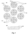
- Schematic views of multi-wire cable 200, flattened tape 300, and laminated wire 400 formed from superconducting wire 100 are shown in Figures 2 and 3, respectively.
- Applications for superconducting wire 100 are found in electromagnetic devices such as, but not limited to: superconducting magnets for motors, transformers, and generators. Such electromagnetic devices may in turn be incorporated into larger systems, such as, for example, a magnetic resonance imaging system.
Landscapes
- Engineering & Computer Science (AREA)
- Manufacturing & Machinery (AREA)
- Superconductors And Manufacturing Methods Therefor (AREA)
- Inorganic Compounds Of Heavy Metals (AREA)
Applications Claiming Priority (2)
| Application Number | Priority Date | Filing Date | Title |
|---|---|---|---|
| US10/691,368 US7226894B2 (en) | 2003-10-22 | 2003-10-22 | Superconducting wire, method of manufacture thereof and the articles derived therefrom |
| US691368 | 2003-10-22 |
Publications (3)
| Publication Number | Publication Date |
|---|---|
| EP1526586A2 true EP1526586A2 (de) | 2005-04-27 |
| EP1526586A3 EP1526586A3 (de) | 2006-06-21 |
| EP1526586B1 EP1526586B1 (de) | 2009-06-03 |
Family
ID=34394544
Family Applications (1)
| Application Number | Title | Priority Date | Filing Date |
|---|---|---|---|
| EP04256454A Expired - Lifetime EP1526586B1 (de) | 2003-10-22 | 2004-10-20 | Herstellungsverfahren für supraleitenden Draht |
Country Status (5)
| Country | Link |
|---|---|
| US (1) | US7226894B2 (de) |
| EP (1) | EP1526586B1 (de) |
| JP (1) | JP4812279B2 (de) |
| CN (1) | CN1619713B (de) |
| DE (1) | DE602004021332D1 (de) |
Cited By (7)
| Publication number | Priority date | Publication date | Assignee | Title |
|---|---|---|---|---|
| GB2448051A (en) * | 2007-03-30 | 2008-10-01 | Gen Electric | Low resistivity joints for joining superconducting wires |
| WO2009127956A1 (en) * | 2008-04-17 | 2009-10-22 | Davide Nardelli | Granular superconducting joint |
| US7615718B2 (en) | 2003-05-30 | 2009-11-10 | Toyota Moto Engineering & Manufacturing North America, Inc. | Apparatus and method for supplying a continuous source of wire |
| US7944208B2 (en) | 2007-11-23 | 2011-05-17 | Paramed Medical Systems, Inc. | Active image area positioning with adjustable patient bench permitting chair-shaped patient transport into and out of an open MRI apparatus system |
| US8378537B2 (en) | 2007-11-27 | 2013-02-19 | Rolls-Royce Plc | Superconducting electrical machine |
| WO2015131930A1 (en) * | 2014-03-04 | 2015-09-11 | European Space Agency | Methods for production of superconducting components |
| EP3683808A4 (de) * | 2018-01-31 | 2021-05-26 | Hitachi, Ltd. | Supraleitender mgb2-draht und herstellungsverfahren dafür |
Families Citing this family (17)
| Publication number | Priority date | Publication date | Assignee | Title |
|---|---|---|---|---|
| JP4010404B2 (ja) * | 2002-12-11 | 2007-11-21 | 株式会社日立製作所 | 超電導線材およびその製法 |
| US7494688B2 (en) * | 2006-07-24 | 2009-02-24 | General Electric Company | Methods for making doped magnesium diboride powders |
| US20080017279A1 (en) * | 2006-07-24 | 2008-01-24 | Venkataramani Venkat Subramani | Wires made of doped magnesium diboride powders and methods for making the same |
| CN101291021B (zh) * | 2007-11-16 | 2011-04-20 | 中国科学院电工研究所 | 一种MgB2带材超导连接方法 |
| US8346326B2 (en) | 2008-01-17 | 2013-01-01 | General Electric Company | Superconductive wire, processes of manufacture and uses thereof |
| US8812069B2 (en) * | 2009-01-29 | 2014-08-19 | Hyper Tech Research, Inc | Low loss joint for superconducting wire |
| DE102009010011B3 (de) | 2009-02-21 | 2010-08-26 | Bruker Eas Gmbh | Verfahren zur Verbindung von zwei oder mehr MgB2-Supraleiterdrähten über einen Presskörper aus HTS-Pulver und supraleitende Verbindungsstelle von zwei oder mehr dieser Drähte |
| DE102009010112B3 (de) * | 2009-02-21 | 2010-09-02 | Bruker Eas Gmbh | Verfahren zur supraleitenden Verbindung von MgB2-Supraleiterdrähten über eine MgB2-Matrix aus einem Mg-infiltrierten Borpulver-Presskörper |
| JP5017310B2 (ja) * | 2009-03-31 | 2012-09-05 | 株式会社日立製作所 | 永久電流スイッチ及び超電導マグネット |
| DE102009043580B4 (de) * | 2009-09-30 | 2017-01-12 | Karlsruher Institut für Technologie | Verfahren zur Herstellung einer Verbindungsstruktur zwischen zwei Supraleitern und Struktur zur Verbindung zweier Supraleiter |
| US10137542B2 (en) | 2010-01-14 | 2018-11-27 | Senvion Gmbh | Wind turbine rotor blade components and machine for making same |
| BR112012017122B1 (pt) | 2010-01-14 | 2021-09-28 | Senvion Gmbh | Feixe compósito para uma pá de turbina eólica |
| EP3327733B1 (de) * | 2015-07-24 | 2023-11-22 | Hitachi, Ltd. | Supraleitender draht, supraleitende spule, mrt und nmr |
| WO2017022124A1 (ja) * | 2015-08-06 | 2017-02-09 | 株式会社シンテック | 医療用線状部材の製造方法 |
| CN105390209A (zh) * | 2015-12-18 | 2016-03-09 | 常熟市东方特种金属材料厂 | 一种高温超导材料 |
| CN108806831A (zh) * | 2018-06-11 | 2018-11-13 | 深圳市金环宇电线电缆有限公司 | 一种电缆用的导电涂料以及石墨烯导电层 |
| CN112967845A (zh) * | 2021-02-26 | 2021-06-15 | 西部超导材料科技股份有限公司 | 一种千米级多芯MgB2超导线材的制备方法 |
Family Cites Families (75)
| Publication number | Priority date | Publication date | Assignee | Title |
|---|---|---|---|---|
| US165100A (en) * | 1875-06-29 | Improvement in hats and caps | ||
| US125213A (en) * | 1872-04-02 | Improvement in fastenings for belts | ||
| US173428A (en) * | 1876-02-15 | Improvement in pegging-machines for boots and shoes | ||
| US164246A (en) * | 1875-06-08 | Improvement in making wire fastenings for bottle-stoppers | ||
| US58143A (en) * | 1866-09-18 | Improvement in corn-harvesters | ||
| US4460A (en) * | 1846-04-18 | Corit-sheller | ||
| US198111A (en) * | 1877-12-11 | Improvement in stop-motions for drawing-frames | ||
| US189533A (en) * | 1877-04-10 | Improvement in process and apparatus for electroplating wire | ||
| US111275A (en) * | 1871-01-24 | Improvement in shuttles for sewing-machines | ||
| US13231A (en) * | 1855-07-10 | Island | ||
| US36482A (en) * | 1862-09-16 | Rigging and spars oe ships and other navigable vessels | ||
| US82412A (en) * | 1868-09-22 | Improvement in earvestebs | ||
| US130130A (en) * | 1872-08-06 | Improvement in bag-holders | ||
| US35039A (en) * | 1862-04-22 | Ventilator for petrol-oil lamps | ||
| US17949A (en) * | 1857-08-04 | Improvement in factitious ivory | ||
| US164418A (en) * | 1875-06-15 | Improvement in shutters for grates | ||
| US38719A (en) * | 1863-06-02 | Improvement in railroad-car trucks | ||
| US99871A (en) * | 1870-02-15 | Improvement in skeleton corsets | ||
| US96711A (en) * | 1869-11-09 | Charles h | ||
| US132739A (en) * | 1872-11-05 | Improvement in bolts for freight-cars | ||
| US150744A (en) * | 1874-05-12 | Improvement in fire-alarms | ||
| US146417A (en) * | 1874-01-13 | Improvement in bag-fasteners | ||
| US51901A (en) * | 1866-01-02 | Daotel t | ||
| US32560A (en) * | 1861-06-18 | Improvement in cultivators | ||
| AT388690B (de) * | 1986-12-18 | 1989-08-10 | Inst Elektroswarki Patona | Verfahren zum widerstands-abbrennstumpfschweissen |
| US5474975A (en) | 1987-04-01 | 1995-12-12 | Semiconductor Energy Laboratory Co., Ltd. | Method for manufacturing an elongated member from a superconducting ceramic material |
| US5082164A (en) | 1990-08-01 | 1992-01-21 | General Electric Company | Method of forming superconducting joint between superconducting tapes |
| US5952270A (en) | 1994-04-29 | 1999-09-14 | American Superconductor Corporation | Process for heat treating superconductor wire |
| US6305070B1 (en) | 1996-10-15 | 2001-10-23 | American Superconductor Corporation | Performance of oxide dispersion strengthened superconductor composites |
| US6586370B1 (en) | 1997-02-26 | 2003-07-01 | Nove' Technologies, Inc. | Metal boride based superconducting composite |
| US5962865A (en) | 1997-04-11 | 1999-10-05 | Trw Inc. | Low inductance superconductive integrated circuit and method of fabricating the same |
| US6038461A (en) | 1997-05-19 | 2000-03-14 | Sakai; Yoshifumi | Plastically deformable high temperature superconductive material and method of manufacturing formed body thereof |
| US6458223B1 (en) | 1997-10-01 | 2002-10-01 | American Superconductor Corporation | Alloy materials |
| JP2939544B1 (ja) | 1998-03-27 | 1999-08-25 | 工業技術院長 | Mgドープ低異方性高温超伝導体とその製造方法 |
| JP3548885B2 (ja) | 1998-08-17 | 2004-07-28 | 株式会社村田製作所 | 誘電体共振器の製造方法 |
| US6541136B1 (en) | 1998-09-14 | 2003-04-01 | The Regents Of The University Of California | Superconducting structure |
| DE69937628T2 (de) | 1998-09-22 | 2008-10-30 | The Furukawa Electric Co., Ltd. | Herstellungsverfahren von aluminium-stabilisiertem supraleitendem draht |
| EP1006594A1 (de) | 1998-12-03 | 2000-06-07 | Jochen Dieter Prof. Dr. Mannhart | Supraleiter mit verbesserter Stromdichte und Verfahren zu dessen Herstellung |
| CA2357019A1 (en) | 1998-12-24 | 2000-07-06 | Pirelli Cavi E Sistemi S.P.A. | Superconducting cable |
| KR20010092758A (ko) | 1998-12-24 | 2001-10-26 | 지아네시 피에르 지오반니 | 초전도 케이블 |
| NZ512544A (en) | 1998-12-24 | 2003-08-29 | Pirelli Cavi E Sistemi Spa | Superconducting cable |
| US6503344B2 (en) | 1999-02-05 | 2003-01-07 | Houghton Durferrit Gmbh | Boronizing agent in paste form |
| US6147032A (en) | 1999-05-19 | 2000-11-14 | Trw Inc. | Method for indirect Ion implantation of oxide superconductive films |
| US6447714B1 (en) | 2000-05-15 | 2002-09-10 | Ut-Battelle, Llc | Method for forming biaxially textured articles by powder metallurgy |
| JP3518745B2 (ja) * | 2000-06-26 | 2004-04-12 | 日立金属株式会社 | 複合蒸着材およびその製造方法 |
| WO2002037581A2 (en) | 2000-09-15 | 2002-05-10 | American Superconductor Corporation | Superconducting article having low ac loss |
| US7351449B2 (en) | 2000-09-22 | 2008-04-01 | N Gimat Co. | Chemical vapor deposition methods for making powders and coatings, and coatings made using these methods |
| US6835425B2 (en) | 2000-12-12 | 2004-12-28 | Konica Corporation | Layer-forming method using plasma state reactive gas |
| JP3575004B2 (ja) | 2001-01-09 | 2004-10-06 | 独立行政法人 科学技術振興機構 | マグネシウムとホウ素とからなる金属間化合物超伝導体及びその金属間化合物を含有する合金超伝導体並びにこれらの製造方法 |
| JP2002222619A (ja) * | 2001-01-24 | 2002-08-09 | Hideyuki Shinagawa | 二硼化マグネシウム超伝導線材 |
| US6514557B2 (en) | 2001-02-15 | 2003-02-04 | Iowa State University Research Foundation | Synthesis of superconducting magnesium diboride objects |
| WO2002069353A1 (en) | 2001-02-28 | 2002-09-06 | Industrial Research Limited | Superconducting borides and wires made thereof |
| US6699820B2 (en) | 2001-03-02 | 2004-03-02 | Hartmut Ulrich Bielefeldt | Method for making a superconductor with enhanced current carrying capability |
| US7018954B2 (en) * | 2001-03-09 | 2006-03-28 | American Superconductor Corporation | Processing of magnesium-boride superconductors |
| US6687975B2 (en) | 2001-03-09 | 2004-02-10 | Hyper Tech Research Inc. | Method for manufacturing MgB2 intermetallic superconductor wires |
| KR100413533B1 (ko) | 2001-03-19 | 2003-12-31 | 학교법인 포항공과대학교 | 초전도 마그네슘 보라이드(MgB₂) 박막의 제조 방법 및제조 장치 |
| DE10114934A1 (de) | 2001-03-22 | 2002-09-26 | Dresden Ev Inst Festkoerper | Verfahren zur Herstellung von supraleitenden Drähten und Bändern auf Basis der Verbindung MgB¶2¶ |
| DE10117877A1 (de) | 2001-04-10 | 2002-10-17 | Max Planck Gesellschaft | Methode zur Herstellung von Magnesiumdiborid sowie von Magnesiumdiborid-Formkörpern aus Magnesiumhydrid und elementarem Bor mittels Puls-Plasma-Synthese |
| JP4556343B2 (ja) * | 2001-04-26 | 2010-10-06 | 住友電気工業株式会社 | 長尺複合体の製造方法 |
| JP4667638B2 (ja) * | 2001-05-09 | 2011-04-13 | 古河電気工業株式会社 | MgB2超電導線の製造方法 |
| KR100863619B1 (ko) | 2001-05-23 | 2008-10-15 | 자이단 호진 고쿠사이 초덴도 산교 기쥬츠 겐큐 센타 | MgB2 단결정체와 그 제조방법 및 MgB2 단결정체를포함하는 초전도재료 |
| KR100388497B1 (ko) | 2001-06-01 | 2003-06-25 | 한국전자통신연구원 | 초전도 에피택셜 박막 및 그 제조 방법 |
| US6630427B2 (en) * | 2001-06-01 | 2003-10-07 | Northwestern University | Superconducting Mg-MgB2 and related metal composites and methods of preparation |
| US20030036482A1 (en) | 2001-07-05 | 2003-02-20 | American Superconductor Corporation | Processing of magnesium-boride superconductors |
| JP4058920B2 (ja) * | 2001-07-10 | 2008-03-12 | 株式会社日立製作所 | 超電導接続構造 |
| KR20030010964A (ko) * | 2001-07-28 | 2003-02-06 | 엘지전자 주식회사 | 마그네슘 다이보라이드 초전도 선재의 제조방법 |
| JP2003086265A (ja) * | 2001-09-12 | 2003-03-20 | Furukawa Electric Co Ltd:The | 超電導線の接続部及びその接続方法 |
| JP2003089516A (ja) * | 2001-09-14 | 2003-03-28 | Internatl Superconductivity Technology Center | MgB2系超電導体並びにMgB2系超電導体の製造方法 |
| US6583362B2 (en) | 2001-11-05 | 2003-06-24 | General Electric Company | Zirconia-stabilized multi-filamentary niobium-tin superconducting wire |
| JP2003158308A (ja) | 2001-11-22 | 2003-05-30 | Communication Research Laboratory | 超伝導材料の製造方法 |
| JP4296256B2 (ja) | 2001-11-22 | 2009-07-15 | 独立行政法人情報通信研究機構 | 超伝導材料の製造方法 |
| US7060174B2 (en) | 2002-02-12 | 2006-06-13 | Japan Atomic Energy Research Institute | Method for electrochemical synthesis of superconducting boron compound MgB2 |
| US6511943B1 (en) | 2002-03-13 | 2003-01-28 | The Regents Of The University Of California | Synthesis of magnesium diboride by magnesium vapor infiltration process (MVIP) |
| CN1168847C (zh) * | 2002-03-30 | 2004-09-29 | 燕山大学 | MgB2超导薄膜的原位热丝化学气相沉积制备方法 |
| ITMI20021004A1 (it) * | 2002-05-10 | 2003-11-10 | Edison Spa | Metodo per la realizzazione di fili superconduttori a base di filamenti cavi di mgb2 |
-
2003
- 2003-10-22 US US10/691,368 patent/US7226894B2/en not_active Expired - Lifetime
-
2004
- 2004-10-20 EP EP04256454A patent/EP1526586B1/de not_active Expired - Lifetime
- 2004-10-20 DE DE602004021332T patent/DE602004021332D1/de not_active Expired - Lifetime
- 2004-10-21 JP JP2004306317A patent/JP4812279B2/ja not_active Expired - Fee Related
- 2004-10-22 CN CN200410103808.9A patent/CN1619713B/zh not_active Expired - Fee Related
Cited By (11)
| Publication number | Priority date | Publication date | Assignee | Title |
|---|---|---|---|---|
| US7615718B2 (en) | 2003-05-30 | 2009-11-10 | Toyota Moto Engineering & Manufacturing North America, Inc. | Apparatus and method for supplying a continuous source of wire |
| GB2448051A (en) * | 2007-03-30 | 2008-10-01 | Gen Electric | Low resistivity joints for joining superconducting wires |
| GB2448051B (en) * | 2007-03-30 | 2011-11-02 | Gen Electric | Low resistivity joints for joining wires and methods for making the same |
| US7944208B2 (en) | 2007-11-23 | 2011-05-17 | Paramed Medical Systems, Inc. | Active image area positioning with adjustable patient bench permitting chair-shaped patient transport into and out of an open MRI apparatus system |
| US8378537B2 (en) | 2007-11-27 | 2013-02-19 | Rolls-Royce Plc | Superconducting electrical machine |
| WO2009127956A1 (en) * | 2008-04-17 | 2009-10-22 | Davide Nardelli | Granular superconducting joint |
| US8229528B2 (en) | 2008-04-17 | 2012-07-24 | Asg Superconductors, S.P.A. | Superconducting coil having a granular superconducting junction |
| US8238990B2 (en) | 2008-04-17 | 2012-08-07 | Asg Superconductors, S.P.A. | Granular superconducting joint |
| WO2015131930A1 (en) * | 2014-03-04 | 2015-09-11 | European Space Agency | Methods for production of superconducting components |
| EP3683808A4 (de) * | 2018-01-31 | 2021-05-26 | Hitachi, Ltd. | Supraleitender mgb2-draht und herstellungsverfahren dafür |
| US11694824B2 (en) | 2018-01-31 | 2023-07-04 | Hitachi, Ltd. | MGB2 superconducting wire material and manufacturing method therefor |
Also Published As
| Publication number | Publication date |
|---|---|
| JP4812279B2 (ja) | 2011-11-09 |
| JP2005129529A (ja) | 2005-05-19 |
| EP1526586B1 (de) | 2009-06-03 |
| DE602004021332D1 (de) | 2009-07-16 |
| EP1526586A3 (de) | 2006-06-21 |
| CN1619713B (zh) | 2011-06-15 |
| US20050090403A1 (en) | 2005-04-28 |
| CN1619713A (zh) | 2005-05-25 |
| US7226894B2 (en) | 2007-06-05 |
Similar Documents
| Publication | Publication Date | Title |
|---|---|---|
| US7226894B2 (en) | Superconducting wire, method of manufacture thereof and the articles derived therefrom | |
| EP0073128B1 (de) | Supraleitender Verbunddraht | |
| US7018954B2 (en) | Processing of magnesium-boride superconductors | |
| EP3107879B1 (de) | Supraleitende drähte und verfahren zur herstellung davon | |
| JP4481584B2 (ja) | 複合シースMgB2超電導線材およびその製造方法 | |
| US3838503A (en) | Method of fabricating a composite multifilament intermetallic type superconducting wire | |
| US3930903A (en) | Stabilized superconductive wires | |
| JP2008226501A (ja) | MgB2超電導線材 | |
| EP0496825A1 (de) | Verfahren zur herstellung elektrischer verbindungen mit hochtemperatursupraleitern unter verwendung metallischer ausgangsstoffe und das daraus gefertigte produkt | |
| JP2002373534A (ja) | 超電導線材とその作製方法及びそれを用いた超電導マグネット | |
| JP4500901B2 (ja) | 複合シースニホウ化マグネシウム超電導線材とその製造方法 | |
| Malagoli et al. | Fabrication and superconducting properties of multifilamentary MgB2 conductors for AC purposes: twisted tapes and wires with very thin filaments | |
| EP0613192B1 (de) | Draht für Nb3X Supraleiterdraht | |
| JP3944573B2 (ja) | Nb3Al超伝導線材の製造方法とその方法により得られるNb3Al超伝導線材 | |
| US20160351781A1 (en) | Ternary molybdenum chalcogenide superconducting wire and manufacturing thereof | |
| EP3961658B1 (de) | Rohling zur herstellung eines langen supraleitenden drahtes auf nb3-sn-basis | |
| JP4013335B2 (ja) | Nb3Sn化合物超電導体の前駆線材およびその製造方法、Nb3Sn化合物超電導導体の製造方法、並びにNb3Sn化合物超電導コイルの製造方法 | |
| WO2014135893A1 (en) | Superconductive wires and associated method of manufacture | |
| JP3673831B2 (ja) | Nb3Sn線材の製造方法 | |
| Randall et al. | Stabilized superconductive wires | |
| WO2002073709A2 (en) | Processing of magnesium-boride superconductors | |
| Pasztor et al. | Development of Nb3Sn Cabled Conductor by External Diffusion Process and the Effect of Strain on the Critical Current | |
| JP3716309B2 (ja) | Nb3Sn線材の製造方法 | |
| De Lima et al. | Superconducting wires of Cu-Nb3Sn: the liquid-phase sintering method | |
| JPH0419919A (ja) | 超電導発電機用Nb↓3Sn超電導線の製造方法 |
Legal Events
| Date | Code | Title | Description |
|---|---|---|---|
| PUAI | Public reference made under article 153(3) epc to a published international application that has entered the european phase |
Free format text: ORIGINAL CODE: 0009012 |
|
| AK | Designated contracting states |
Kind code of ref document: A2 Designated state(s): AT BE BG CH CY CZ DE DK EE ES FI FR GB GR HU IE IT LI LU MC NL PL PT RO SE SI SK TR |
|
| AX | Request for extension of the european patent |
Extension state: AL HR LT LV MK |
|
| PUAL | Search report despatched |
Free format text: ORIGINAL CODE: 0009013 |
|
| AK | Designated contracting states |
Kind code of ref document: A3 Designated state(s): AT BE BG CH CY CZ DE DK EE ES FI FR GB GR HU IE IT LI LU MC NL PL PT RO SE SI SK TR |
|
| AX | Request for extension of the european patent |
Extension state: AL HR LT LV MK |
|
| 17P | Request for examination filed |
Effective date: 20061221 |
|
| 17Q | First examination report despatched |
Effective date: 20070125 |
|
| AKX | Designation fees paid |
Designated state(s): DE FR GB |
|
| RIC1 | Information provided on ipc code assigned before grant |
Ipc: H01L 39/24 20060101AFI20080929BHEP |
|
| RTI1 | Title (correction) |
Free format text: MANUFACTURING METHOD FOR SUPERCONDUCTING WIRE |
|
| GRAP | Despatch of communication of intention to grant a patent |
Free format text: ORIGINAL CODE: EPIDOSNIGR1 |
|
| GRAS | Grant fee paid |
Free format text: ORIGINAL CODE: EPIDOSNIGR3 |
|
| GRAA | (expected) grant |
Free format text: ORIGINAL CODE: 0009210 |
|
| AK | Designated contracting states |
Kind code of ref document: B1 Designated state(s): DE FR GB |
|
| REG | Reference to a national code |
Ref country code: GB Ref legal event code: FG4D |
|
| REF | Corresponds to: |
Ref document number: 602004021332 Country of ref document: DE Date of ref document: 20090716 Kind code of ref document: P |
|
| PLBE | No opposition filed within time limit |
Free format text: ORIGINAL CODE: 0009261 |
|
| STAA | Information on the status of an ep patent application or granted ep patent |
Free format text: STATUS: NO OPPOSITION FILED WITHIN TIME LIMIT |
|
| 26N | No opposition filed |
Effective date: 20100304 |
|
| REG | Reference to a national code |
Ref country code: FR Ref legal event code: PLFP Year of fee payment: 12 |
|
| REG | Reference to a national code |
Ref country code: FR Ref legal event code: PLFP Year of fee payment: 13 |
|
| REG | Reference to a national code |
Ref country code: FR Ref legal event code: PLFP Year of fee payment: 14 |
|
| REG | Reference to a national code |
Ref country code: FR Ref legal event code: PLFP Year of fee payment: 15 |
|
| PGFP | Annual fee paid to national office [announced via postgrant information from national office to epo] |
Ref country code: FR Payment date: 20190919 Year of fee payment: 16 |
|
| PGFP | Annual fee paid to national office [announced via postgrant information from national office to epo] |
Ref country code: GB Payment date: 20190923 Year of fee payment: 16 |
|
| PGFP | Annual fee paid to national office [announced via postgrant information from national office to epo] |
Ref country code: DE Payment date: 20190918 Year of fee payment: 16 |
|
| REG | Reference to a national code |
Ref country code: DE Ref legal event code: R119 Ref document number: 602004021332 Country of ref document: DE |
|
| GBPC | Gb: european patent ceased through non-payment of renewal fee |
Effective date: 20201020 |
|
| PG25 | Lapsed in a contracting state [announced via postgrant information from national office to epo] |
Ref country code: FR Free format text: LAPSE BECAUSE OF NON-PAYMENT OF DUE FEES Effective date: 20201031 Ref country code: DE Free format text: LAPSE BECAUSE OF NON-PAYMENT OF DUE FEES Effective date: 20210501 |
|
| PG25 | Lapsed in a contracting state [announced via postgrant information from national office to epo] |
Ref country code: GB Free format text: LAPSE BECAUSE OF NON-PAYMENT OF DUE FEES Effective date: 20201020 |