EP1526384A2 - Abdeckgläsertransfervorrichtung für Probenabdichtapparat - Google Patents
Abdeckgläsertransfervorrichtung für Probenabdichtapparat Download PDFInfo
- Publication number
- EP1526384A2 EP1526384A2 EP04024893A EP04024893A EP1526384A2 EP 1526384 A2 EP1526384 A2 EP 1526384A2 EP 04024893 A EP04024893 A EP 04024893A EP 04024893 A EP04024893 A EP 04024893A EP 1526384 A2 EP1526384 A2 EP 1526384A2
- Authority
- EP
- European Patent Office
- Prior art keywords
- cover glass
- elevating member
- glass
- suction
- cover
- Prior art date
- Legal status (The legal status is an assumption and is not a legal conclusion. Google has not performed a legal analysis and makes no representation as to the accuracy of the status listed.)
- Withdrawn
Links
Images


Classifications
-
- G—PHYSICS
- G01—MEASURING; TESTING
- G01N—INVESTIGATING OR ANALYSING MATERIALS BY DETERMINING THEIR CHEMICAL OR PHYSICAL PROPERTIES
- G01N35/00—Automatic analysis not limited to methods or materials provided for in any single one of groups G01N1/00 - G01N33/00; Handling materials therefor
- G01N35/02—Automatic analysis not limited to methods or materials provided for in any single one of groups G01N1/00 - G01N33/00; Handling materials therefor using a plurality of sample containers moved by a conveyor system past one or more treatment or analysis stations
- G01N35/04—Details of the conveyor system
-
- B—PERFORMING OPERATIONS; TRANSPORTING
- B65—CONVEYING; PACKING; STORING; HANDLING THIN OR FILAMENTARY MATERIAL
- B65H—HANDLING THIN OR FILAMENTARY MATERIAL, e.g. SHEETS, WEBS, CABLES
- B65H3/00—Separating articles from piles
- B65H3/08—Separating articles from piles using pneumatic force
- B65H3/0808—Suction grippers
- B65H3/0816—Suction grippers separating from the top of pile
-
- G—PHYSICS
- G01—MEASURING; TESTING
- G01N—INVESTIGATING OR ANALYSING MATERIALS BY DETERMINING THEIR CHEMICAL OR PHYSICAL PROPERTIES
- G01N35/00—Automatic analysis not limited to methods or materials provided for in any single one of groups G01N1/00 - G01N33/00; Handling materials therefor
- G01N35/00029—Automatic analysis not limited to methods or materials provided for in any single one of groups G01N1/00 - G01N33/00; Handling materials therefor provided with flat sample substrates, e.g. slides
-
- G—PHYSICS
- G02—OPTICS
- G02B—OPTICAL ELEMENTS, SYSTEMS OR APPARATUS
- G02B21/00—Microscopes
- G02B21/34—Microscope slides, e.g. mounting specimens on microscope slides
Definitions
- the present invention relates to a cover glass transfer device for a sample sealing apparatus for affixing a cover glass to a glass slide so as to seal a sample on a glass slide, which comprises an automated process of affixing a cover glass stacked in layers to a glass slide.
- a sample sealing operation comprising the steps of: placing the cell sample piece on a glass slide, which is a piece of glass; dropping on to the cell sample piece a solution, which is an adhesive agent, for sample sealing; further placing a cover glass made of a thin glass plate thereon to sandwich the cell sample piece between the glass slide and the cover glass; and sealing the cell sample piece.
- a cover glass transfer device which picks up and transfers a cover glass from a case onto a glass slide so as to seal a cell sample piece between the glass slide and the cover glass.
- Fig. 7 shows a process for picking up a cover glass by a cover glass transfer device.
- the reference numeral 201 denotes a cover glass housing case in which the opening edge, labeled R, is curved in a convex manner with respect to the inside of the case.
- the reference numeral 202 denotes cover glasses stacked in layers in the case 201 at an inclined angle ⁇ 3 each having one end thereof, in the longitudinal direction of the cover glass, raised.
- the reference numeral 203 denotes a cover glass holding rod (to be hereafter referred to as a holding rod) which has a hollow structure inside thereof for holding a cover glass by suction. It is movable in a vertical direction and is supported by an elevating member (not shown). The upper end part of the holding rod 203 is led to a vacuum pump (not shown). The vacuum pump is switched, for example, to connect to the holding rod 203, or to the atmosphere, via an electromagnetic switching valve (not shown). This electromagnetic switching valve normally connects the holding rod 203 with the vacuum pump, and is controlled by a switching device (not shown) to switch to the atmosphere after the cover glass 202 has been affixed onto a glass slide.
- a suction pad 206 is fixed, which comprises an attaching face with an inclined angle ⁇ 3 identical to that of the cover glasses 202 stacked in layers.
- the reference numeral 204 denotes a cover glass separating metal tool provided above the opening edge part of the case 201.
- the reference numeral 205 denotes a cover glass separating pawl, provided above the opening edge part of the case 201 on the opposite side to that of the cover glass separating metal tool 204.
- the cover glass separating metal tool 204 is fixed at a position higher than that of the cover glass separating pawl 205. As shown in Fig. 7 both the ends of the cover glass 202a, held by the holding rod 203 at the inclined angle ⁇ 3, engage the cover glass separating metal tool 204 and the cover glass separating pawl 205 at almost the same time.
- the elevating member descends, driven by an elevating drive mechanism (not shown), the holding rod 203 descends toward the top cover glass 202a of the layered stack in the case 201. Thereafter, the suction pad 206 stops descending when coming into contact with the top cover glass 202a, and holds the cover glass 202a by suction. After the cover glass 202a has been held by suction, the elevating member allows the holding rod 203 to ascend. At this time, an adjacent lower cover glass 202b in the stack may also be picked up - being attached to the lower face of the cover glass 202a.
- both longitudinally oriented ends of the held top cover glass 202a engage the separating metal tool 204 and the separating pawl 205 provided above both the opening edge parts of the cover glass housing case 201. Since the holding rod 203 continues to move upward, the cover glass 202a begins to adopt an upwardly convex deflection.
- the cover glass 202b falls, due to its own weight, the falling cover glass 202b is guided into case 201 by the curved opening edge R of the housing case 201, allowing the cover glass 202b to slip smoothly into the housing case 201.
- the still attached cover glass 202a After having passed beyond the cover glass separating pawl 205, the still attached cover glass 202a returns to its flat state at the inclined angle ⁇ 3, and then proceeds to the process shown in Fig. 8 where it is affixed onto a glass slide placed on a glass slide placing base.
- the reference numeral 207 denotes a glass slide placed on a glass slide placing base (not shown).
- a cell sample piece 208 is affixed onto the glass slide 207, and a sealing adhesive solution 209 is dropped onto second end portion of the glass slide 207 (the right side of the glass slide 207 in Fig. 8).
- the holding rod 203 is positioned above the first end portion which is the other end portion with respect to the second end portion of the glass slide 207 on which the sealing adhesive solution 209 has been dropped.
- the cover glass 202a on the first end side is sucked by the suction pad 206 at the inclined angle ⁇ 3. Therefore, at the beginning of the affixation process, the cover glass 202a is held hanging from the suction pad 206 fixed on the holding rod 203 so as to be brought downward at the inclined angle ⁇ 3. Then, the cover glass 202a proceeds in the affixation process initially having the inclined angle ⁇ 3.
- an elevating member brings the holding rod 203 down until the lower-end edge of the inclined cover glass 202a contacts the second end portion of the glass slide 207.
- Fig. 8 illustrates the aforementioned state wherein the lower-end edge works as a fulcrum, and the suction pad 206 as a working point.
- a push rod 210 is provided to the elevating member in a vertically movable manner.
- the inclined cover glass 202a is further deflected by the push rod 210 so as to bend it and then to have a larger inclined angle on the upper-end edge portion of the inclined cover glass 202a exceeding ⁇ 3.
- the push rod 210 is disposed to escape from far above the cover glass 202 during the pick up process shown in Fig. 7.
- push rod drive means (not shown) operates such that the push rod 210 moves downwards to bend and to push the cover glass 202a toward the glass slide 207.
- the cover glass 202a has been progressively pushed onto the glass slide 207 from one side thereof while being bent due to the descent of the push rod 210 and the suction pad 206.
- the suction pad 206 and the push rod 210 both ascend, thereby completing the sealing operation.
- the cell sample piece 208 can be sealed between the glass slide 207 and the cover glass 202a without the inclusion of air bubbles.
- the top cover glass can be picked up, one at a time, by separating and dropping the adjacent lower cover glass and then be transferred onto a glass slide without the inclusion of air bubbles between the glass slide and the cover glass.
- the falling lower cover glass may not return onto the normal stacking position as getting stuck on the edge or the side wall of a case.
- the falling distance becomes large such that the possibility that the cover glass does not return to the normal stacking position becomes higher.
- An object of the present invention is to provide a cover glass transfer device always capable of maintaining a cover glass to be separated off to the normal stacking position.
- a cover glass transfer device for a sample sealing apparatus performing the steps of: sequentially picking up a top cover glass of a plurality of cover glasses stacked in layers by picking up means; and affixing the picked up cover glass onto a glass slide to seal a sample on the glass slide
- the picking up means has: an elevating member capable of moving up and down above the plurality of cover glasses stacked in layers; a holding member movable up and down for a certain stroke with respect to the elevating member, the holding member having a suction member for vacuuming the cover glass at its distal end, the suction member coming into contact with the upper face of the top cover glass on a first end side; and a push member movable up and down for a certain stroke with respect to the elevating member, the push member being attached while provided with a downward pressure, the lower end part of the push member coming into contact with the top cover glass at a position between the sucked portion with the suction member and the portion of the cover glass on a second
- the plurality of cover glasses are stacked in layers at an inclined angle such that a portion of the cover glass opposite to the suction member is positioned below a portion of the cover glass opposite to the push member.
- the descending velocity of the elevating member is controlled in accordance with a stacked height of the plurality of cover glasses when the elevating member descends.
- the cover glass is held by the holding member in a state where the held cover glass is separated from the adjacent lower cover glass stacked in layers by the ascent of the elevating member and an inclined posture of the cover glass is maintained by allowing the suction member to be placed at an upper position than that of the pushing member being in contact with the cover glass in rear of the suction member, and the elevating member descends toward the glass slide in order to affix the held cover glass onto the glass slide while maintaining the inclined posture thereof.
- the cover glass when an elevating member starts to ascend for picking up a cover glass, upward force acts on the first end side of the top cover glass held by suction with a suction member provided to a holding member, thereby providing downward working force by a push member, for example, onto the almost longitudinal center part of the cover glass.
- a push member for example, onto the almost longitudinal center part of the cover glass.
- the cover glass is deflected downward in a state where one end of the cover glass is pushed onto the adjacent lower cover glass.
- the curvature due to the deflection changes in accordance with the ascent of the elevating member, even when attaching to the top cover glass held by suction, the adjacent lower cover glass cannot follow the change of enlarging the deflection, thereby separating the adjacent lower cover glass.
- the separation operation described above is carried out in the position of the top cover glass stacked in layers such that the cover glass separated off naturally falls on the normal position of the top cover glass. Accordingly, the effect can be obtained, wherein a cover glass is sequentially picked up without causing any trouble for the next picking-up.
- a cover glass which has been affixed can be separated off with a simple mechanism wherein a time shift is produced when a holding member and a push member ascend together with the elevating member.
- the curvature of the cover glass held by suction is significantly varied such that the cover glass is separated off in the position of the top cover glass stacked in layers. Therefore, unlike the conventional technique, there is no need to provide a cover glass separating member above the opening edge part of the case and an inwardly convex rounded part R of the opening part of the case, thereby realizing the downsizing of the apparatus.
- the shape of the case is also simplified.
- a stand-by state is defined as that the suction face of the suction member provided at the distal end of a holding rod is positioned above the lower end of a push member.
- the timing when the suction member sucks the top cover glass upon the descent of the elevating member is delayed by the time period corresponding to the move of the height difference in accordance with an inclined angle of the placed top cover glass.
- the top cover glass held with the holding rod by suction can be deflected in accordance with this delayed time period, thereby reliably separating an adjacent lower cover glass which has been affixed.
- the stacking height is lowered such that a descending elevating member cannot stop at a given position due to an increase in acceleration.
- the elevating member can reliably stop at a given position by decelerating the descending velocity of the elevating member when the stacking height is lowered.
- a cover glass held by suction is inclined by maintaining the state when the cover glass stacked in layers is picked up and is affixed to a glass slide.
- the cover glass is moved over the glass slide, and the elevating member is allowed to descend to bring the inclined lower end of the cover glass into contact with the second end side of the glass slide.
- the elevating member is allowed to further descend slightly to deflect the cover glass downward convexly by pushing with the push member.
- the cover glass is affixed completely by gradually pushing the suction side thereof. After the suction member is opened to the atmosphere to release the sucking and holding, the affixation is completed.
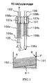
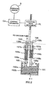
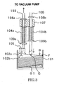
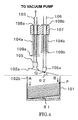
- Figs. 1 to 5 show preferred embodiments of the present invention.
- Figs. 1 to 3 are front views of a cover glass pick up portion of a cover glass transfer device for a sample sealing apparatus, illustrating a process for picking up a cover glass from a case.
- the reference numeral 101 denotes a cover glass housing case
- the reference numeral 102 denotes a cover glass.
- the case 101 of the present embodiment is provided with a base member, having an inclined angle ⁇ 1, at the bottom thereof such that the cover glasses 102 stacked in layers are housed at the inclined angle ⁇ 1 where one longitudinally oriented end edge B of the cover glass 102 is raised.
- Edge B refers to the upper-end edge of an inclined cover glass 102
- edge A refers to the lower end edge of the inclined cover glass 102.
- the inclined angle ⁇ 1 is an angle opposite in inclination to that of the conventional example shown in Fig. 7.
- the present case is such that a cover glass holding rod 103, which will be described later, is disposed on the proximal side of the lower-end edge A of the inclined cover glass 102.
- the reference numeral 103 denotes the cover glass holding rod (to be hereafter simply referred to as a holding rod) for holding a cover glass by suction.
- the reference numeral 106 denotes a cover glass push rod (to be hereafter referred to as a PS rod). These rods are supported by an elevating member 107 in a manner in which they are movable up and down.
- the elevating member 107 is driven by an elevating drive mechanism EL using, as a drive source, an elevating motor comprising a pulse motor for example.
- the control of the elevating drive mechanism EL is carried out by a control apparatus CA, which controls the whole structure of the sample sealing device.
- the elevating member 107 starts to descend due to a descending operation of the elevating drive mechanism EL. This is after a descent instruction is given to the elevating member 107 at a particular time after placing a glass slide on a glass slide placing base.
- the drive control is initiated.
- a ball screw provided to the elevating member 107 and the lead screw are screwed together to move the elevating member 107.
- the holding rod 103 and the PS rod 106 are inserted through insertion holes 107a and 107b, respectively, which are formed in the elevating member 107 in a vertical direction thereof.
- the insertion hole 107a is positioned above the edge A of the cover glasses 102 stacked in layers in the case 101, and the holding rod 103 is inserted therethrough (107a).
- the insertion hole 107b is positioned above edge B of the cover glasses 102 stacked in layers in the case 101, and the PS rod 106 is inserted therethrough (107b).
- Stopper rings 108a and 108b capable of coming into contact with the upper face of the elevating member 107, are fixed on the upper part of the holding rod 103 and the PS rod 106, respectively. These stopper rings 108a and 108b separately control the lower parts of the holding rod 103 and the PS rod 106.
- spring fixation rings 109a and 109b are separately fixed below the lower face of the elevating member 107.
- a holding rod spring 104a consisting of a compressed coil spring is elastically installed.
- a PS rod spring 104b consisting of a compressed coil spring is elastically installed.
- the holding rod 103 and the PS rod 106 are independently supported and guided in a slidable manner, in a vertical direction, between the stopper rings 108a and 108b and the spring fixation rings 109a and 109b, respectively. At the same time they are biased downward by the spring force of each of the compressed coil springs, the holding rod spring 104a and the PS rod spring 104b.
- the holding rod 103 is formed to be hollow inside.
- the upper end part thereof is led to a vacuum pump so as to be switched to between the vacuum pump and the atmospheric side via an electromagnetic switching valve (not shown).
- the switching valve is normally connected to the vacuum pump and is controlled to be switchable to the atmospheric side at the end of the process, wherein a cover glass has been attached as an addition.
- a cover glass suction pad 105 (to be hereafter referred to as a suction pad), which is rotatable due to a bent neck part of a hinged part thereof, is fixed.
- the suction pad 105 can attach to a cover glass 102, when in a vacuum condition by means of the aforementioned vacuum pump, when the suction face of the suction pad 105 comes into contact with the cover glass 102.
- a cap 106a - a protecting member made of a hard rubber, for example - is provided in order to protect the cover glass 102 from damage when the PS rod comes into contact therewith.
- the PS rod 106 is provided with a pressure sensor S on the lower end part of the PS rod, which detects a pushing pressure onto a cover glass.
- a detection signal, generated by the pressure sensor S, is transmitted to the control apparatus CA as shown in Fig. 2 such that the appropriate drive control of the elevating drive mechanism EL is carried out based on the detection signal.
- the pressure sensor S may be provided on the axis part of the PS rod 106, rather than on the lower end part thereof.
- Fig. 1 shows a first step of a cover glass pick-up process.
- the elevating member 107 is in a stand-by state in which it is disposed above the case 101.
- the holding rod 103 and the PS rod 106, inserted through the elevating member 107 have been separately pushed down by means of the spring force of the holding rod spring 104a and the PS rod spring 104b, respectively, to the position where the stopper rings 108a and 108b of these rods have come into contact with the upper face of the elevating member 107.
- This state as shown in Fig. 1, is defined as a stand-by state.
- the holding rod 103 and the PS rod 106 are set such that the position of the suction face of the suction pad 105 provided on the lower end part of the holding rod 103 is higher in elevation than the lower end part of the cap 106a provided on the lower end part of the PS rod 106. Further, the PS rod 106 is set to come into contact with an almost central part (in a longitudinal direction) of a cover glass when descending toward the case 101.
- the elevating member 107 starts to descend at a velocity V1 (S1) and the control apparatus determines whether the pressure sensor S provided on the PS rod 106 detects the pressure generated when that the PS rod 106 comes into contact with the cover glass 102a within a predetermined time (T1) (S2).
- the elevating member 107 descends at a constant velocity, based on the determination that there is a long distance between the elevating member 107 and the cover glass 102a until the above pressure sensor S detects the aforementioned contacting pressure (S3).
- the descent velocity of the elevating member 107 is slowed on the determination that there is now only a short distance between the elevating member 107 and the cover glass 102a (S4).
- the elevating member 107 stops its descent when the pressure sensor S of the suction pad 105 detects that the suction pad has attached by suction to the cover glass 102a (S5).
- the PS rod 106 which has first come into contact with the cover glass 102a, cannot further descend after its contact with the cover glass 102a such that only the elevating member 107 continues to descend with respect to the PS rod 106. At this time, the PS rod spring 104b is compressed, thereby imparting a downward spring force on to the PS rod 106.
- the suction pad 105 of the holding rod 103 comes into contact with the cover glass 102a, following contact by the PS rod 106. Thereafter, the holding rod 103 cannot further descend such that only the elevating member 107 continues to descend with respect to the holding rod 103. At this time, the holding rod spring 104a is compressed, thereby imparting a downward spring force on to the holding rod 103. Therefore, the suction pad 105 attaches by suction to the cover glass 102a.
- Fig. 3 shows a second step of the cover glass pick-up process.
- the elevating member 107 starts to ascend.
- the holding rod 103 starts to ascend together with the elevating member 107 after the stopper ring 108a fixed on the holding rod 103 has come into contact with the upper end face of the elevating member 107.
- the cover glass 102a is held by suction from the suction pad 105 of the holding rod 103 near edge A of the cover glass 102a.
- the cover glass 102a is subsequently lifted clockwise about fulcrum P, which is where edge B of the cover glass 102a contacts those cover glasses stacked in layers beneath it.
- the cover glass 102a is lifted about fulcrum P by the attachment point of the suction pad 105.
- the stopper ring 108b of the PS rod 106 has clearance with respect to the elevating member 107 such that the PS rod 106 is further biased downward by the PS rod spring 104b, thereby providing a downward pressure to a contacting point Q - which is where the PS rod comes into contact with the cover glass 102a.
- the cover glass 102a is loaded having a fulcrum P on edge B thereof, a working point towards edge A to which an upward force is provided, and a working point (which is the contacting point on the PS rod 106) to which a downward force is provided.
- a large downward convex deflection is provided to the entire cover glass 102a by the contacting point of the PS rod 106 to the side of the suction pad 105.
- the amount of this deflection becomes larger as the elevating member 107 ascends, such that the curvature of the cover glass 102a held by suction by the suction pad 105 gradually becomes large.
- the upward force provided by the suction pad 105 to cover glass 102a is not provided to the adjacent lower cover glasses 102b thereunder. Therefore, the cover glasses 102b cannot follow the change in the radius of curvature created on the cover glass 102a attached to the suction pad 105, thereby causing the separation of the adjacent lower cover glass 102b therefrom.
- the separation of the cover glass 102b is performed while the cover glass 102a remains in contact at its edge B with lower stacked layers of cover glasses 102b.
- the adjacent lower separated cover glass 102b returns to, or remains in, its initial normal place in the stack to be subjected to the next pick-up by suction means. Therefore, unlike the conventional method, there is no need to provide a separating member above the opening edge part of the case 101 in order to separate an adjacent affixed cover glass. Also, there is no need to provide the curved part R on the opening edge part of the case 101 for guiding a separated cover glass 102b to its normal stacking position. As a result, the suction pad 105 can properly hold, by suction, a single cover glass 102a in a sequential order from the stack.
- Fig. 4 shows a third step of the cover glass pick-up process.
- the cover glass 102a separates from the top layer cover glass of the remaining cover glasses 102b stacked in layers. Then, the cover glass 102a recovers its flat state upon being released from deflection. At this time, since the cap 106b has been set to be disposed lower in elevation than the suction pad 105 (as described above), the cover glass 102a proceeds to a cover glass affixation process while being held by suction at an inclined angle ⁇ 2.
- Fig. 5 shows the cover glass affixation process.
- Fig. 5 shows the operational process to attach, as an addition, the cover glass 102a held by suction by the holding rod 103 to a glass slide 110 placed on a glass slide placing base (not shown). This is followed by sealing a cell sample piece 111 on the glass slide 110 with the aid of a sealing adhesive solution 112.
- the PS rod 106 inserted through the elevating member 107 is disposed at a position corresponding to a second end of the glass slide 110 onto which the adhesive solution was dropped.
- the side of the glass slide 110 onto which the adhesive solution 112 was dropped will be hereafter referred to as the "second end" of the glass slide 110.
- the holding rod 103 inserted through the elevating member 107 is disposed at a position corresponding to the other end of the glass slide 110.
- the other side of the glass slide 110 onto which the adhesive solution 112 was dropped will be hereafter referred to as the "first end" of the glass slide 110.
- the cover glass 102a which is held by suction with the suction pad 105 of the holding rod 103 on the other end thereof, is contacted with the PS rod 106 at a point marked Q near its almost longitudinal center part.
- the cover glass 102a When the elevating member 107 further descends, the cover glass 102a is pushed toward, and is affixed to, the glass slide 110 by the PS rod 106 and the suction pad 105. By thus pushing the cover glass 102a gradually, starting from the side where the adhesive solution 112 was dropped, the cell sample piece 111 is able to be sealed between the glass slide 110 and the cover glass 102a without the inclusion of air bubbles.
- the cover glass 102a is picked up in the state where the cover glasses 102 are stacked in layers in the case 101 at the inclined angle ⁇ 1.
- the cover glasses 102 may be stacked horizontally, and may not be stacked in layers in the case 101.
- the holding rod 103 and the PS rod 106 descend from the position of their stand-by state described above while posturing at the above inclined angle ⁇ 2 - which is an angle lowering toward the bottom right, and formed by a tangent line between the lower end of the cap 106a of the PS rod 106 and the suction face of the suction pad 105 fixed on the holding rod 103.
- the cap 106a of the PS rod 106 comes into contact with the top cover glass 102
- the suction pad 105 of the holding rod 103 comes into contact with the top cover glass 102.
- the stopper ring 108a of the holding rod 103 first comes into contact with the upper face of the elevating member 107, allowing the holding rod 103 to move upward when the elevating member 107 starts to ascend. Then, the PS rod 103 pushes the cover glass 102 downward at the almost longitudinal center part of the cover glass 102, thereby deflecting downward the cover glass 102 at a fulcrum, the one end thereof, to change the curvature of the cover glass 102. Therefore, the cover glass 102a is naturally separated from adjacent lower cover glasses in the stack.
- the separating operation of the top cover glass 102a is carried out in the state that the cover glass 102a comes into contact with the second end of the adjacent lower cover glass 102b. It is merely necessary to stack a plurality of cover glasses 102 in layers, without any need to accommodate them in a container-like case.
Landscapes
- Physics & Mathematics (AREA)
- Analytical Chemistry (AREA)
- General Physics & Mathematics (AREA)
- Chemical & Material Sciences (AREA)
- Immunology (AREA)
- Biochemistry (AREA)
- General Health & Medical Sciences (AREA)
- Life Sciences & Earth Sciences (AREA)
- Health & Medical Sciences (AREA)
- Pathology (AREA)
- Optics & Photonics (AREA)
- Engineering & Computer Science (AREA)
- Mechanical Engineering (AREA)
- Microscoopes, Condenser (AREA)
- Sampling And Sample Adjustment (AREA)
- Apparatus Associated With Microorganisms And Enzymes (AREA)
Applications Claiming Priority (2)
| Application Number | Priority Date | Filing Date | Title |
|---|---|---|---|
| JP2003363410A JP2005127848A (ja) | 2003-10-23 | 2003-10-23 | 標本封入機のカバーグラス移載装置 |
| JP2003363410 | 2003-10-23 |
Publications (2)
| Publication Number | Publication Date |
|---|---|
| EP1526384A2 true EP1526384A2 (de) | 2005-04-27 |
| EP1526384A3 EP1526384A3 (de) | 2006-05-03 |
Family
ID=34386526
Family Applications (1)
| Application Number | Title | Priority Date | Filing Date |
|---|---|---|---|
| EP04024893A Withdrawn EP1526384A3 (de) | 2003-10-23 | 2004-10-20 | Abdeckgläsertransfervorrichtung für Probenabdichtapparat |
Country Status (3)
| Country | Link |
|---|---|
| US (1) | US20050135918A1 (de) |
| EP (1) | EP1526384A3 (de) |
| JP (1) | JP2005127848A (de) |
Cited By (5)
| Publication number | Priority date | Publication date | Assignee | Title |
|---|---|---|---|---|
| WO2010080131A1 (en) * | 2008-12-19 | 2010-07-15 | Abbott Labortories | Method and apparatus for detecting microscope slide coverslips |
| ITBO20100746A1 (it) * | 2010-12-21 | 2012-06-22 | Marchesini Group Spa | Metodo per alimentare fustellati ad una apparecchiatura di marcatura, dispositivo di trasporto di fustellati e dispositivo di trasferimento di fustellati |
| EP2653418A3 (de) * | 2011-11-01 | 2014-06-25 | Koat B.V. | Plano-Blattzuführvorrichtung |
| CN104903697A (zh) * | 2012-12-26 | 2015-09-09 | 文塔纳医疗系统公司 | 自动化标本处理系统以及对准和运输承载标本的显微镜载片的方法 |
| CN105916787A (zh) * | 2013-12-19 | 2016-08-31 | 肖特兄弟公司 | 织物定位装置 |
Families Citing this family (16)
| Publication number | Priority date | Publication date | Assignee | Title |
|---|---|---|---|---|
| CN100343735C (zh) * | 2006-01-24 | 2007-10-17 | 旭东机械(昆山)有限公司 | 取料装置 |
| DE102011003375B4 (de) * | 2011-01-31 | 2014-07-24 | Leica Biosystems Nussloch Gmbh | Vorrichtung und Verfahren zum Handhaben von Deckgläsern für Objektträger |
| JP6113725B2 (ja) * | 2011-07-22 | 2017-04-12 | ロッシュ ダイアグノスティクス ヘマトロジー インコーポレイテッド | 試料移送システムおよび移送方法 |
| US10011444B2 (en) | 2012-11-02 | 2018-07-03 | Packaging Progressions, Inc. | Bacon card feeding system |
| US9309059B2 (en) * | 2012-11-02 | 2016-04-12 | Packaging Progressions, Inc. | Bacon card feeding system |
| JP6527177B2 (ja) * | 2014-06-30 | 2019-06-05 | ベンタナ メディカル システムズ, インコーポレイテッド | 自動標本処理システムおよび方法 |
| CN110095857B (zh) * | 2014-07-09 | 2021-06-08 | 文塔纳医疗系统公司 | 自动盖片机及使用方法 |
| CN106629154B (zh) * | 2016-10-26 | 2019-03-01 | 蔡江波 | 一种纸张真空吸附分离处理方法 |
| JP6921673B2 (ja) * | 2017-07-25 | 2021-08-18 | Pacraft株式会社 | ピックアップ方法及びピックアップ装置 |
| CN107421776B (zh) * | 2017-09-12 | 2023-07-25 | 云南电网有限责任公司玉溪供电局 | 变压器绝缘油密封取样装置 |
| KR102153400B1 (ko) * | 2018-08-10 | 2020-09-08 | (주)아스토 | 커버 글라스 부착 장치 |
| CN110733913A (zh) * | 2019-11-12 | 2020-01-31 | 江苏创源电子有限公司 | 一种软板吸附机构及上板机 |
| CN111620122B (zh) * | 2020-06-29 | 2024-10-25 | 深圳至峰精密制造有限公司 | 玻片装载设备及方法 |
| CN112394504B (zh) * | 2020-11-17 | 2023-01-03 | 济南艾迪康医学检验中心有限公司 | 盖玻片取放盒和盖玻片取放装置及盖玻片取放方法 |
| CN112763299B (zh) * | 2020-12-21 | 2024-07-26 | 广东金泉医疗科技有限公司 | 盖玻片吸取和按压封片装置及自动封片设备 |
| CN114772332B (zh) * | 2022-06-21 | 2022-09-30 | 赫比(成都)精密塑胶制品有限公司 | 堆叠金属薄片分片机械臂及分片方法 |
Family Cites Families (9)
| Publication number | Priority date | Publication date | Assignee | Title |
|---|---|---|---|---|
| US2203823A (en) * | 1938-09-21 | 1940-06-11 | Chandler & Price Co | Sheet separating and feeding mechanism for printing presses |
| BE791606A (fr) * | 1972-07-10 | 1973-03-16 | Pilot Pen Co Ltd | Procede et appareil pour aspirer et soulever la feuille la plussuperieure d'une pile de feuilles de ce type |
| US4428793A (en) * | 1981-08-25 | 1984-01-31 | Meisei Electric Co., Ltd. | Preparation method for a microscopic specimen and a device therefor |
| EP0333872B1 (de) * | 1987-09-18 | 1995-08-23 | Wacoh Corporation | Greifer für Roboter |
| JPH0295627A (ja) * | 1988-09-30 | 1990-04-06 | Omron Tateisi Electron Co | 紙葉類の繰出・集積装置 |
| AUPM352194A0 (en) * | 1994-01-25 | 1994-02-17 | Australian Biomedical Corporation Limited | Instrument for automatically applying coverslips and method |
| JP3570817B2 (ja) * | 1996-06-04 | 2004-09-29 | 株式会社千代田製作所 | 顕微鏡標本のカバーガラス取出し及び取付け方法 |
| US6568447B1 (en) * | 1999-05-11 | 2003-05-27 | Kabushiki Kaisha Tiyoda Seisakusho | Cover glass adhering device |
| DE10144048B4 (de) * | 2001-09-07 | 2012-09-20 | Leica Mikrosysteme Gmbh | Vorrichtung und Verfahren zum Handhaben von Deckgläsern für Objektträger |
-
2003
- 2003-10-23 JP JP2003363410A patent/JP2005127848A/ja active Pending
-
2004
- 2004-10-19 US US10/967,259 patent/US20050135918A1/en not_active Abandoned
- 2004-10-20 EP EP04024893A patent/EP1526384A3/de not_active Withdrawn
Cited By (10)
| Publication number | Priority date | Publication date | Assignee | Title |
|---|---|---|---|---|
| WO2010080131A1 (en) * | 2008-12-19 | 2010-07-15 | Abbott Labortories | Method and apparatus for detecting microscope slide coverslips |
| US8213001B2 (en) | 2008-12-19 | 2012-07-03 | Abbott Laboratories | Method and apparatus for detecting microscope slide coverslips |
| ITBO20100746A1 (it) * | 2010-12-21 | 2012-06-22 | Marchesini Group Spa | Metodo per alimentare fustellati ad una apparecchiatura di marcatura, dispositivo di trasporto di fustellati e dispositivo di trasferimento di fustellati |
| EP2468664A1 (de) * | 2010-12-21 | 2012-06-27 | Marchesini Group S.p.A. | Verfahren zur Lieferung von Rohteilen zu einer Markierungsvorrichtung, eine Beförderungsvorrichtung zum Transportieren von Rohteilen und eine Übertragungsvorrichtung für Rohteile |
| US8690518B2 (en) | 2010-12-21 | 2014-04-08 | Marchesini Group S.P.A. | Method for supplying blanks to a marking apparatus, a conveyor device for transporting blanks and a transfer device for blanks |
| EP2653418A3 (de) * | 2011-11-01 | 2014-06-25 | Koat B.V. | Plano-Blattzuführvorrichtung |
| CN104903697A (zh) * | 2012-12-26 | 2015-09-09 | 文塔纳医疗系统公司 | 自动化标本处理系统以及对准和运输承载标本的显微镜载片的方法 |
| CN105916787A (zh) * | 2013-12-19 | 2016-08-31 | 肖特兄弟公司 | 织物定位装置 |
| CN105916787B (zh) * | 2013-12-19 | 2018-08-28 | 肖特兄弟公司 | 织物定位装置 |
| US10407262B2 (en) | 2013-12-19 | 2019-09-10 | Short Brothers Plc | Fabric positioning apparatus |
Also Published As
| Publication number | Publication date |
|---|---|
| EP1526384A3 (de) | 2006-05-03 |
| JP2005127848A (ja) | 2005-05-19 |
| US20050135918A1 (en) | 2005-06-23 |
Similar Documents
| Publication | Publication Date | Title |
|---|---|---|
| EP1526384A2 (de) | Abdeckgläsertransfervorrichtung für Probenabdichtapparat | |
| EP1499548B1 (de) | Verfahren und vorrichtung zum automatisierten aufnehmen und ablegen von deckgläsern | |
| KR100979474B1 (ko) | 반도체 다이의 픽업 장치 및 픽업 방법 | |
| CN110095857B (zh) | 自动盖片机及使用方法 | |
| JP4397429B1 (ja) | 半導体ダイのピックアップ装置及びピックアップ方法 | |
| US8007741B1 (en) | Pipetting head with plate gripper | |
| US20090101282A1 (en) | Apparatus and method for picking-up semiconductor dies | |
| KR101685459B1 (ko) | 피펫이 포함된 시료용기를 이용한 자동 도말장치 | |
| KR101218662B1 (ko) | 칩 픽업 장치, 칩 픽업 방법, 칩 박리 장치 및 칩 박리방법 | |
| JPH075573U (ja) | ラベルの取り上げ装置 | |
| CN101009996A (zh) | 支持单元与具有该支持单元的拾取装置 | |
| JPS626171A (ja) | 試料容器の栓脱着装置 | |
| JP2003118859A (ja) | 可撓性板状体の取出装置および取出方法 | |
| KR102127695B1 (ko) | 반도체 다이 분리장치 | |
| KR20060047924A (ko) | 다이 픽업 장치 | |
| JPH09240869A (ja) | 板材の1枚取り方法およびその装置 | |
| CN108858266A (zh) | 磁力抓手 | |
| CN119427406B (zh) | 一种能够自动捋直fpc的机械手执行端及方法 | |
| JPH0639768A (ja) | 真空吸着装置 | |
| JPH06329286A (ja) | 板状物体のピックアップ装置 | |
| CN222994489U (zh) | 一种酶免检测仪自动拼杯装置以及酶免检测仪 | |
| CN216104808U (zh) | 一种用于显示模组的拾取机构及上料装置 | |
| JPH04107997A (ja) | 電子部品搭載装置及び電子部品の搭載方法 | |
| JPH07187427A (ja) | 板材分離取出し装置 | |
| JP2007173663A (ja) | チップピックアップ装置およびチップピックアップ方法ならびにチップ剥離装置およびチップ剥離方法 |
Legal Events
| Date | Code | Title | Description |
|---|---|---|---|
| PUAI | Public reference made under article 153(3) epc to a published international application that has entered the european phase |
Free format text: ORIGINAL CODE: 0009012 |
|
| 17P | Request for examination filed |
Effective date: 20041026 |
|
| AK | Designated contracting states |
Kind code of ref document: A2 Designated state(s): AT BE BG CH CY CZ DE DK EE ES FI FR GB GR HU IE IT LI LU MC NL PL PT RO SE SI SK TR |
|
| AX | Request for extension of the european patent |
Extension state: AL HR LT LV MK |
|
| PUAL | Search report despatched |
Free format text: ORIGINAL CODE: 0009013 |
|
| AK | Designated contracting states |
Kind code of ref document: A3 Designated state(s): AT BE BG CH CY CZ DE DK EE ES FI FR GB GR HU IE IT LI LU MC NL PL PT RO SE SI SK TR |
|
| AX | Request for extension of the european patent |
Extension state: AL HR LT LV MK |
|
| 17Q | First examination report despatched |
Effective date: 20060928 |
|
| AKX | Designation fees paid |
Designated state(s): DE FR GB |
|
| STAA | Information on the status of an ep patent application or granted ep patent |
Free format text: STATUS: THE APPLICATION IS DEEMED TO BE WITHDRAWN |
|
| 18D | Application deemed to be withdrawn |
Effective date: 20070209 |