EP1525841A1 - Appareil et procédé de traitement d'images du fond de l'oeil - Google Patents
Appareil et procédé de traitement d'images du fond de l'oeil Download PDFInfo
- Publication number
- EP1525841A1 EP1525841A1 EP04022830A EP04022830A EP1525841A1 EP 1525841 A1 EP1525841 A1 EP 1525841A1 EP 04022830 A EP04022830 A EP 04022830A EP 04022830 A EP04022830 A EP 04022830A EP 1525841 A1 EP1525841 A1 EP 1525841A1
- Authority
- EP
- European Patent Office
- Prior art keywords
- image
- funduscopic
- aperture mask
- image processing
- processing unit
- Prior art date
- Legal status (The legal status is an assumption and is not a legal conclusion. Google has not performed a legal analysis and makes no representation as to the accuracy of the status listed.)
- Granted
Links
Images


Classifications
-
- A—HUMAN NECESSITIES
- A61—MEDICAL OR VETERINARY SCIENCE; HYGIENE
- A61B—DIAGNOSIS; SURGERY; IDENTIFICATION
- A61B3/00—Apparatus for testing the eyes; Instruments for examining the eyes
- A61B3/10—Objective types, i.e. instruments for examining the eyes independent of the patients' perceptions or reactions
- A61B3/12—Objective types, i.e. instruments for examining the eyes independent of the patients' perceptions or reactions for looking at the eye fundus, e.g. ophthalmoscopes
-
- A—HUMAN NECESSITIES
- A61—MEDICAL OR VETERINARY SCIENCE; HYGIENE
- A61B—DIAGNOSIS; SURGERY; IDENTIFICATION
- A61B3/00—Apparatus for testing the eyes; Instruments for examining the eyes
- A61B3/10—Objective types, i.e. instruments for examining the eyes independent of the patients' perceptions or reactions
- A61B3/14—Arrangements specially adapted for eye photography
Definitions
- the present invention relates to a technology suitable for funduscopic image processing for displaying a funduscopic image output from a fundus camera used in departments of ophthalmology and internal medicine.
- the present invention relates to a funduscopic image processing unit for correctly displaying a funduscopic image output from a fundus camera used in departments of ophthalmology and internal medicine.
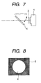
- FIG. 7 shows a periphery of a photographic camera of a fundus camera having means for photographing an aperture mask.
- an aperture mask plate 3 having a circular opening 2 provided in the center and a shading part around it, is arranged as shown in FIG. 8.
- a funduscopic image is caught in the center of a photographic light flux from a photographic optical system of a fundus camera, but a flare is mixed with the funduscopic image in the perimeter, and undesired reflection and the like are mixed with the funduscopic image outside the perimeter, so that the opening 2 of an effective region for diagnosis, is preferably clarified by an aperture mask plate 3.
- the aperture mask plate 3 has to be arranged in such a vicinity of the imaging face of a photographic camera 1 as not to blur a mask border.
- various filters and a changeover mirror 4 are arranged right in front of an imaging face, it is rather difficult to further install the aperture mask plate 3 there.
- the camera has to optically reimage an aperture mask plate 3 and a funduscopic image in order to photograph an image of the aperture mask plate 3, as a result, needs to make an optical path longer, an optical system complicated and the number of mechanisms increased, and causes problems of an increase of the cost and the like.
- a fundus camera which in order to reduce the cost, miniaturizes the unit and reduces the weight, simplifies the optical system and mechanisms, eliminates the above described aperture mask plate 3, and makes the whole image of a photographically effective area of a photographic optical system produced on the imaging face.
- the photographic system eliminates an optical system for reimaging, thereby miniaturizes a fundus camera itself, and reduces the cost.
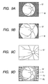
- FIGS. 9A to 9D there are various types in funduscopic images photographed by a conventional fundus camera, as shown in FIGS. 9A to 9D.
- FIGS. 9A and 9B show funduscopic images with the use of an aperture mask plate 3
- FIGS. 9C and 9D show funduscopic images without the use of an aperture mask plate 3.
- FIG. 9A shows a funduscopic image of an ocular fundus, which shows an orbicular funduscopic image Er', is photographed at the same view angles both in vertical and horizontal directions, and catches an aperture mask image M in the perimeter.
- the photographic optical system effectively arranges both of an effective optical path and an imaging face therein, and catches a funduscopic image Er' as an oval and oblong shape in a horizontal direction and an aperture mask image M around it.
- FIG. 9C the photographic optical system arranges all imaging faces inside a photographing light flux, and catches a funduscopic image Er' on the whole image plane.
- FIG. 9D shows a funduscopic image Er' which schematically shows a flare, and in which flares F1, F2 and F3 are sequentially caught outside an effective funduscopic image Er'.
- the flare F1 is an area in which a funduscopic image is photographed together with a flare.
- a funduscopic image an image in a fundus camera and a flare are shown.
- a blurred image in a fundus camera is darkly shown.
- Japanese Patent Application Laid-Open No. H09-206278 it is disclosed to electrically and electronically add an aperture mask image to a funduscopic image photographed by the above fundus camera.
- the present invention has been accomplished in view of the above problems, and is directed to providing a suitable technology for funduscopic image processing for displaying a funduscopic image which is output from a fundus camera used in departments of ophthalmology or internal medicine.
- a funduscopic image processing unit of the present invention comprises the following arrangement.
- a funduscopic image processing unit comprises: image-inputting means for inputting funduscopic image data, and image-processing means for carrying out a predetermined image processing to the funduscopic image data, wherein the predetermined image processing is carried out on the basis of a determination result of aperture mask determination means for determining the presence or absence of an aperture mask image in the funduscopic image data.
- a funduscopic image processing method of the present invention comprises the following arrangement.
- a funduscopic image processing method comprises: an image-inputting step for inputting funduscopic image data, and image-processing step for carrying out a predetermined image processing to the funduscopic image data, wherein the predetermined image processing is carried out on the basis of a determination result in an aperture mask determination step for determining the presence or absence of an aperture mask image in the funduscopic image data.
- FIG. 1 shows a block diagram of a fundus camera without means for photographing an aperture mask.
- the fundus camera has, on an optical path to an object lens 12 from an alignment light source 11 for observation such as a lamp, a condensing lens 13, a light source 14 for photographing a static image such as a stroboscope, a condensing lens 15, a mirror 16, a lens 17, an aperture 18 having a ring-shaped opening, a relay lens 19, and an apertured mirror 20 having an aperture in a central part, sequentially disposed.
- a fundus camera also has, on an optical path at the rear of an opening mirror 20, a movable focus lens 21, a taking lens 22 having a scaling function, a changeover mirror 23 and a camera 24 for photographing a high-definition static image, sequentially arranged therein; has a high-sensitivity camera 25 for observing a moving image arranged in the reflecting direction of the changeover mirror 23; and has a focus knob 26 installed to drive the focus lens 21 and the taking lens 22.
- a flux of light emitted from a light source 11 for alignment for observation passes through a condensing lens 13, a light source 14 for photographing a static image and a condensing lens 15, then is reflected upward by a mirror 16, then passes through a lens 17, a ring-shaped opening of an aperture 18 and a relay lens 19, then is reflected toward left by an opening mirror 20, and passes through an objective lens 12 to illuminate an ocular fundus Er through a pupil Ep of an eye to be examined E.
- a reflected light from thus illuminated ocular fundus Er passes through the pupil Ep, the objective lens 12, a focus lens 21 and a taking lens 22, then is reflected downward by a changeover mirror 23, and produces an image as a funduscopic image Er', on the imaging face of a camera 25 for observing a moving image.
- a photographer confirms a photographing portion, alignment and a focal condition while observing a funduscopic image Er' through a monitor which is not be shown, and when the image is out of focus, a photographer adjusts the focus by moving a focus lens 21 to an optical axis direction through an operation for a focus knob 26.
- an examiner pushes a photographic switch which is not shown, then a changeover mirror 23 retreats to the outside of an optical path, and a light is emitted from a light source 14 for photographing a static image.
- the flux of light passes through a lens 15 and then an optical path similar to the flux of the light emitted from a light source 11 for observation and alignment, and illuminates an ocular fundus Er.
- the reflected light from the ocular fundus Er passes through a pupil Ep, then an objective lens 12, an opening mirror 20, a focus lens 21 and a taking lens 22, and forms an image as a funduscopic image Er' on the imaging face of a camera 24 for photographing the static image.
- An image formed on the imaging face is only a central effective part without a flare of a photographed funduscopic image Er'.
- the photographed image is converted to electric signals in a camera 24 for photographing a static image, and then is displayed on a monitor.
- the funduscopic image Er' is stored in a storage unit which is not shown, and is transferred via a communication line and a network.
- FIG. 2 shows a block diagram in an image processing unit.
- the output of a fundus camera 31 for photographing an image without an aperture mask is connected to a funduscopic image processing unit 32.
- the signals of a funduscopic image Er' output from a fundus camera 31 is connected to an image-inputting section 33 in the funduscopic image processing unit 32, and the output of an image-inputting section 33 is sequentially connected to an aperture mask-forming section 35 through an aperture mask determination section 34, and then to an image-outputting section 37 through an aperture mask combine section 36.
- the output of an aperture mask-forming section 35 is connected to the aperture mask combine section 36 and the image-outputting section 37, and the image-outputting section 37 is connected to an external image diagnosis display device 38.
- a photographed funduscopic image is sent to an image-inputting section 33 in a funduscopic image processing unit 32, and is developed in a memory for image processing, which is not shown, and there initialized so that it can be treated in an aperture mask determination section 34 and an aperture mask combine section 36.
- the aperture mask determination section 34 it is determined whether an aperture mask image M has to be added to a funduscopic image Er', or not, by a method described below.
- a necessary mask is formed in an aperture mask-forming section 35, an aperture mask image M combined with the formed mask is produced in the aperture mask combine section 36, the format is converted in the image-outputting section 37, and the combined image is output to an image diagnosis display device 38.
- the aperture mask image formed in an aperture mask-forming section 35 can be independently output to an image-outputting section 37, and when an image diagnosis display device 38 has an overlay function, a funduscopic image and an aperture mask image can be separately input, overlaid and displayed.
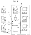
- FIG. 3 shows a block diagram in the case of photographing funduscopic images with several different fundus cameras in the embodiment 2.
- a fundus camera 41 for forming a funduscopic image having no aperture mask image
- a fundus camera 42 forming an image catching an aperture mask
- a fundus camera 43 of which the whole image is a funduscopic image.
- a hospital 44 there installed are another fundus camera 45, an image server 46 for accumulating image data and an image-storing section 47, and to a server 46, a funduscopic image processing unit 48 is connected.
- the fundus camera 45 and image diagnosis display devices 50, 51 and 52 are connected through a network 49.
- the funduscopic images photographed with the fundus cameras 41, 42 and 43 outside the hospital 44 are input in the image server 46 in the hospital 44 and is kept in the image-storing section 47 through removable storage media 53, 54 and 55.
- the funduscopic images photographed with fundus cameras 41, 42 and 43 are photographed into various forms as shown in FIGS. 9A to 9D.
- a request asking to display a funduscopic image Er' is output to an image server 46, for instance, from a funduscopic image processing unit 32 shown in FIG. 2, the image server 46 searches the funduscopic image Er' in an image-storing section 47 and sends it to a funduscopic image processing unit 48.
- the funduscopic image processing unit 48 determines whether the aperture mask image as described in FIG. 2 exists in the funduscopic image, or not, produces an image combined with an aperture mask in accordance with the result, and returns a resultant image to the image server 46.
- the processing unit 48 can appropriately add them the aperture mask image so as to be displayed together with it.
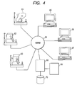
- FIG. 4 shows a block diagram of an image processing unit in the case of connecting several different fundus cameras in the embodiment 3 via the Internet.
- the outputs of fundus cameras 61, 62 and 63 are connected to diagnostic-imaging display units 65, 66 and 67 of a terminal and to an image server 68, through an Internet network 64, and further to an image server 68, a funduscopic image processing unit 69 and an image-storing section 70 are connected.
- photographed images with fundus cameras 61, 62 and 63 for outputting various funduscopic images as in the case of the embodiment 2 are temporarily sent to an image server 68 via an Internet network 64, and are memorized and kept in an image-storing section 70.
- the image ) server 68 searches funduscopic images Er' matching to the requests, sends them to a funduscopic image processing unit 69, receives the processing result, and sends the images to requestors.
- the aperture mask processing described above is carried out, and the images having an aperture mask image M correctly added, are sent to the terminals of the image requestors.
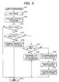
- FIG. 5 shows a flow chart of a determination method for determining the presence or absence of an ) aperture mask image, which has been carried out in each embodiment.
- the determination starts in a step S101, and an image to be detected is input to a memory in a step S102.
- image processing means carries out a histogram processing in a step S103. In the case of a color image, the histogram processing is carried out after being converted to brightness information.
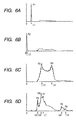
- the result of histogram processing is output as shown in FIG. 6A, for instance.
- the horizontal axis shows a pixel value. In the case of an 8-bit image, an origin point is 0 and the right end is 255. In the case of a 10-bit image, the right end is 1023. The right end shows the highest brightness level.
- the vertical axis shows a frequency count, and shows that the number of pixels having a certain level increases with the height.
- the peaks of the vertical axis are arranged and normalized, so that the value itself of the vertical axis does not indicate a frequency count.
- FIGS. 6A to 6D show the result of histogram processing for each funduscopic image shown in FIGS. 9A to 9D.
- the horizontal axis shows an image value, which increases toward a right side. In other words, when the image value is brightness, a larger value indicates higher luminosity.
- the vertical axis indicates the frequency count of pixels having the value of the level. Because each graphical view is normalized so as to match with the maximum value of the peak, the height of the vertical axis can not be compared each other among graphical views.
- the aperture mask image M has the luminous level of an approximately equal value, and as a result, shows sharp peaks P1 and P2 as shown in FIGS. 6A and 6B.
- the level value L1 in FIG. 6A, and the level value L2 in FIG. 6B are the level values L.
- the difference in the level values L is attributed to the difference in a black level between photographic cameras.
- a determination section uses the fact that a funduscopic image Er' having an aperture mask image M has a sharp peak with a small width at the position not larger than a predetermined level value, as a criterion of determination.
- FIG. 6C shows a histogram for a funduscopic image displayed in the whole image plane.
- the histogram contains almost all image values (pixel values) in an intermediate level, and besides has no sharp peak with a small width.
- the histogram has a peak in a brighter level than that in an ocular fundus, and because the funduscopic image has a dark image further in the periphery, the histogram has some peaks appearing in the low levels which mean the dark space of a funduscopic image.
- an aperture mask determination section After carrying out histogram processing, an aperture mask determination section carries out peak detection processing in a step S104 on the basis of the result, specifically, detects one peak on the basis of an inclination of an ascent, a vertex, an inclination of a descent, a height and a half width, of the peaks.
- the determination section When the determination section has detected the peak, it proceeds to a step S105, and when having detected no such a peak, it proceeds to the determination-finishing step of a step S112 and completes the determination steps.
- a determination section determines whether the peak detected in a step S104 is equal to or less than a predetermined value L, or not. Because an aperture mask image M caught in the periphery of a funduscopic image Er' is dark and has a low level, the determination section determines whether the image contains the aperture mask or not from a determination level L. If the level is lower than the determination level L, the determination section determines that there is the aperture mask image, and proceeds to a step S106, and then to the determination-finishing step of a step S112 and completes the determination steps.
- a determination section When a detected level is determined to be not lower than a determination level L in a step S105, a determination section goes to a step S107. There, the determination section determines the width of the whole image from the result of the peak detection while considering the whole image as a mountain, determines the width of the mountain on the basis of a half value (height) of the obtained lowest peak, and compares the width with a determination value W. If the width of the mountain is less than a determination value W, it means that a level of an image is concentrated in a central part, and in a step S108, the determination section determines that the whole image is a funduscopic image, goes to a step S112 and completes the determination steps.
- the determination section goes to a step S109, and in the step S109, determines that there is no aperture mask image M, and then image processing means calculates the size of the aperture mask image M in a step S110.
- a funduscopic image processing unit correctly determines whether a funduscopic image output from various imaging types of fundus cameras have an aperture mask area or not, determines whether the funduscopic image contains an unnecessary area for interpretation of a funduscopic image or not, and produces a funduscopic image combined with an aperture mask so as to correspond to the area. Accordingly, a diagnostician can safely diagnosis the symptom from the image with little fear of a wrong diagnosis.
- a funduscopic image processing unit can put an aperture mask to an image having no aperture mask, and sends it when sending the image, thereby an interpretation doctor does not need a special image processing unit, and can diagnose the symptom with a general-purpose display unit.
- the present invention provides a technology suitable for funduscopic image processing for displaying a funduscopic image outputted from a fundus camera used in departments of ophthalmology and internal medicine.
- the object of the present invention is also achieved by supplying a recording medium (or a storage medium) that records a program code of software which realizes the functions of the above described embodiments, to a system or an apparatus, and making the computer (or CPU or MPU) of the system or the apparatus read and carry out the program code stored in the recording medium.
- the program code read from the recording medium by itself realizes the functions of the above described embodiments, and the recording medium which records the program code constitutes the present invention.
- the present invention includes not only the case in which the functions of the above described embodiments are realized by the execution of the program code read by the computer, but also the case in which the functions of the above described embodiments are realized by the processing by an operating system (OS) or the like operating on the computer which carries out one or all of actual treatment on the basis of directions from the program code.
- OS operating system
- the present invention includes the case in which the program code read from the recording medium is written on a functionality expansion card inserted to the computer or a memory installed in a functionality expansion unit connected to the computer, and then a CPU mounted on the functionality expansion card or the functionality expansion unit carries out one or all of the actual processing on the basis of directions of the program code, and the functions of the above described embodiments are realized by the processing.
Applications Claiming Priority (2)
| Application Number | Priority Date | Filing Date | Title |
|---|---|---|---|
| JP2003364399 | 2003-10-24 | ||
| JP2003364399A JP4336561B2 (ja) | 2003-10-24 | 2003-10-24 | 眼底画像処理装置 |
Publications (2)
| Publication Number | Publication Date |
|---|---|
| EP1525841A1 true EP1525841A1 (fr) | 2005-04-27 |
| EP1525841B1 EP1525841B1 (fr) | 2007-04-11 |
Family
ID=34386542
Family Applications (1)
| Application Number | Title | Priority Date | Filing Date |
|---|---|---|---|
| EP04022830A Not-in-force EP1525841B1 (fr) | 2003-10-24 | 2004-09-24 | Appareil et procédé de traitement d'images du fond de l'oeil |
Country Status (8)
| Country | Link |
|---|---|
| US (1) | US7333636B2 (fr) |
| EP (1) | EP1525841B1 (fr) |
| JP (1) | JP4336561B2 (fr) |
| KR (1) | KR100684300B1 (fr) |
| CN (1) | CN100379381C (fr) |
| AT (1) | ATE359024T1 (fr) |
| DE (1) | DE602004005798D1 (fr) |
| TW (1) | TWI292706B (fr) |
Families Citing this family (5)
| Publication number | Priority date | Publication date | Assignee | Title |
|---|---|---|---|---|
| US20070092753A1 (en) * | 2005-10-26 | 2007-04-26 | Eastman Kodak Company | Organic element for low voltage electroluminescent devices |
| TWI453523B (zh) | 2011-12-29 | 2014-09-21 | Ind Tech Res Inst | 具有自動對焦功能之診斷設備 |
| JP5587480B2 (ja) * | 2013-09-30 | 2014-09-10 | 株式会社ニデック | 眼底カメラ |
| CN106408564B (zh) * | 2016-10-10 | 2019-04-02 | 北京新皓然软件技术有限责任公司 | 一种基于深度学习的眼底图像处理方法、装置及系统 |
| CN110448265B (zh) * | 2018-05-08 | 2021-07-27 | 广西师范学院 | 一种双折射晶体快拍穆勒矩阵成像测偏眼底系统 |
Citations (2)
| Publication number | Priority date | Publication date | Assignee | Title |
|---|---|---|---|---|
| JPH03193026A (ja) * | 1989-12-25 | 1991-08-22 | Canon Inc | 画像処理装置 |
| JPH09206278A (ja) * | 1996-02-05 | 1997-08-12 | Canon Inc | 眼科画像処理装置 |
Family Cites Families (5)
| Publication number | Priority date | Publication date | Assignee | Title |
|---|---|---|---|---|
| JPS55101241A (en) * | 1979-01-30 | 1980-08-01 | Tokyo Optical | Eyeground camera equipped with operation distance detector |
| US4715703A (en) * | 1982-10-12 | 1987-12-29 | Rodenstock Instrument Corporation | Ocular-fundus analyzer |
| ES2152946T3 (es) * | 1992-02-18 | 2001-02-16 | Neopath Inc | Metodo de identificacion de objetos mediante tecnicas de procesamiento de datos. |
| US5455644A (en) * | 1992-02-28 | 1995-10-03 | Canon Kabushiki Kaisha | Ophthalmologic apparatus having an examining system for examining the fundus of an eye |
| US7055955B2 (en) * | 2001-02-27 | 2006-06-06 | Canon Kabushiki Kaisha | Eye fundus examination apparatus |
-
2003
- 2003-10-24 JP JP2003364399A patent/JP4336561B2/ja not_active Expired - Fee Related
-
2004
- 2004-09-15 TW TW093127901A patent/TWI292706B/zh not_active IP Right Cessation
- 2004-09-24 AT AT04022830T patent/ATE359024T1/de not_active IP Right Cessation
- 2004-09-24 EP EP04022830A patent/EP1525841B1/fr not_active Not-in-force
- 2004-09-24 DE DE602004005798T patent/DE602004005798D1/de active Active
- 2004-10-20 KR KR1020040083905A patent/KR100684300B1/ko not_active IP Right Cessation
- 2004-10-21 US US10/970,337 patent/US7333636B2/en not_active Expired - Fee Related
- 2004-10-22 CN CNB2004100870148A patent/CN100379381C/zh not_active Expired - Fee Related
Patent Citations (2)
| Publication number | Priority date | Publication date | Assignee | Title |
|---|---|---|---|---|
| JPH03193026A (ja) * | 1989-12-25 | 1991-08-22 | Canon Inc | 画像処理装置 |
| JPH09206278A (ja) * | 1996-02-05 | 1997-08-12 | Canon Inc | 眼科画像処理装置 |
Non-Patent Citations (2)
| Title |
|---|
| PATENT ABSTRACTS OF JAPAN vol. 015, no. 450 (C - 0885) 15 November 1991 (1991-11-15) * |
| PATENT ABSTRACTS OF JAPAN vol. 1997, no. 12 25 December 1997 (1997-12-25) * |
Also Published As
| Publication number | Publication date |
|---|---|
| KR20050039585A (ko) | 2005-04-29 |
| ATE359024T1 (de) | 2007-05-15 |
| CN1608578A (zh) | 2005-04-27 |
| EP1525841B1 (fr) | 2007-04-11 |
| TW200518713A (en) | 2005-06-16 |
| CN100379381C (zh) | 2008-04-09 |
| US7333636B2 (en) | 2008-02-19 |
| US20050089207A1 (en) | 2005-04-28 |
| JP4336561B2 (ja) | 2009-09-30 |
| DE602004005798D1 (de) | 2007-05-24 |
| KR100684300B1 (ko) | 2007-02-16 |
| TWI292706B (en) | 2008-01-21 |
| JP2005124879A (ja) | 2005-05-19 |
Similar Documents
| Publication | Publication Date | Title |
|---|---|---|
| US8118430B2 (en) | Opthalmologic imaging apparatus and opthalmologic imaging method | |
| EP1797816B1 (fr) | Dispositif et méthode pour traitement d'images du fond de l'oeil | |
| US20120147327A1 (en) | Ophthalmologic photographing apparatus and camera for use in ophthalmologic photographing | |
| US7445337B2 (en) | Ophthalmic image sensing apparatus | |
| EP1525841B1 (fr) | Appareil et procédé de traitement d'images du fond de l'oeil | |
| JP7301052B2 (ja) | 眼科撮影装置 | |
| JP2000197608A (ja) | 眼科撮影装置 | |
| JP4731703B2 (ja) | 眼科装置 | |
| JP3805232B2 (ja) | 眼科装置 | |
| KR100770523B1 (ko) | 안과촬영장치 | |
| JP2003210409A (ja) | 眼底カメラ | |
| JP2001137192A (ja) | 眼科撮影装置及び方法及び記憶媒体 | |
| JPH105179A (ja) | 眼科撮影装置 | |
| JP4532943B2 (ja) | 眼科用画像処理装置及び処理方法 | |
| JP2004267614A (ja) | 眼科撮影装置 | |
| JP2003204939A (ja) | 眼科撮影装置 | |
| JP4208636B2 (ja) | 眼科撮影装置 | |
| JP2000271088A (ja) | 眼底撮影装置 | |
| JP2003052636A (ja) | 眼科撮影装置 | |
| JP2003210410A (ja) | 眼底カメラ | |
| JPH0484933A (ja) | 眼科撮影装置 | |
| JPH11225969A (ja) | 眼底カメラ | |
| JP2006102096A (ja) | 眼科用画像処理装置 | |
| JPH0484932A (ja) | 眼科撮影装置 | |
| JPH04220232A (ja) | 眼科用カメラ |
Legal Events
| Date | Code | Title | Description |
|---|---|---|---|
| PUAI | Public reference made under article 153(3) epc to a published international application that has entered the european phase |
Free format text: ORIGINAL CODE: 0009012 |
|
| AK | Designated contracting states |
Kind code of ref document: A1 Designated state(s): AT BE BG CH CY CZ DE DK EE ES FI FR GB GR HU IE IT LI LU MC NL PL PT RO SE SI SK TR |
|
| AX | Request for extension of the european patent |
Extension state: AL HR LT LV MK |
|
| 17P | Request for examination filed |
Effective date: 20051027 |
|
| AKX | Designation fees paid |
Designated state(s): AT BE BG CH CY CZ DE DK EE ES FI FR GB GR HU IE IT LI LU MC NL PL PT RO SE SI SK TR |
|
| GRAP | Despatch of communication of intention to grant a patent |
Free format text: ORIGINAL CODE: EPIDOSNIGR1 |
|
| GRAS | Grant fee paid |
Free format text: ORIGINAL CODE: EPIDOSNIGR3 |
|
| GRAA | (expected) grant |
Free format text: ORIGINAL CODE: 0009210 |
|
| AK | Designated contracting states |
Kind code of ref document: B1 Designated state(s): AT BE BG CH CY CZ DE DK EE ES FI FR GB GR HU IE IT LI LU MC NL PL PT RO SE SI SK TR |
|
| PG25 | Lapsed in a contracting state [announced via postgrant information from national office to epo] |
Ref country code: FI Free format text: LAPSE BECAUSE OF FAILURE TO SUBMIT A TRANSLATION OF THE DESCRIPTION OR TO PAY THE FEE WITHIN THE PRESCRIBED TIME-LIMIT Effective date: 20070411 Ref country code: SI Free format text: LAPSE BECAUSE OF FAILURE TO SUBMIT A TRANSLATION OF THE DESCRIPTION OR TO PAY THE FEE WITHIN THE PRESCRIBED TIME-LIMIT Effective date: 20070411 Ref country code: CH Free format text: LAPSE BECAUSE OF FAILURE TO SUBMIT A TRANSLATION OF THE DESCRIPTION OR TO PAY THE FEE WITHIN THE PRESCRIBED TIME-LIMIT Effective date: 20070411 Ref country code: LI Free format text: LAPSE BECAUSE OF FAILURE TO SUBMIT A TRANSLATION OF THE DESCRIPTION OR TO PAY THE FEE WITHIN THE PRESCRIBED TIME-LIMIT Effective date: 20070411 |
|
| REG | Reference to a national code |
Ref country code: GB Ref legal event code: FG4D |
|
| REG | Reference to a national code |
Ref country code: CH Ref legal event code: EP |
|
| REG | Reference to a national code |
Ref country code: IE Ref legal event code: FG4D |
|
| REF | Corresponds to: |
Ref document number: 602004005798 Country of ref document: DE Date of ref document: 20070524 Kind code of ref document: P |
|
| PG25 | Lapsed in a contracting state [announced via postgrant information from national office to epo] |
Ref country code: SE Free format text: LAPSE BECAUSE OF FAILURE TO SUBMIT A TRANSLATION OF THE DESCRIPTION OR TO PAY THE FEE WITHIN THE PRESCRIBED TIME-LIMIT Effective date: 20070711 |
|
| PG25 | Lapsed in a contracting state [announced via postgrant information from national office to epo] |
Ref country code: ES Free format text: LAPSE BECAUSE OF FAILURE TO SUBMIT A TRANSLATION OF THE DESCRIPTION OR TO PAY THE FEE WITHIN THE PRESCRIBED TIME-LIMIT Effective date: 20070722 |
|
| PG25 | Lapsed in a contracting state [announced via postgrant information from national office to epo] |
Ref country code: PT Free format text: LAPSE BECAUSE OF FAILURE TO SUBMIT A TRANSLATION OF THE DESCRIPTION OR TO PAY THE FEE WITHIN THE PRESCRIBED TIME-LIMIT Effective date: 20070911 |
|
| NLV1 | Nl: lapsed or annulled due to failure to fulfill the requirements of art. 29p and 29m of the patents act | ||
| REG | Reference to a national code |
Ref country code: CH Ref legal event code: PL |
|
| PG25 | Lapsed in a contracting state [announced via postgrant information from national office to epo] |
Ref country code: AT Free format text: LAPSE BECAUSE OF FAILURE TO SUBMIT A TRANSLATION OF THE DESCRIPTION OR TO PAY THE FEE WITHIN THE PRESCRIBED TIME-LIMIT Effective date: 20070411 Ref country code: PL Free format text: LAPSE BECAUSE OF FAILURE TO SUBMIT A TRANSLATION OF THE DESCRIPTION OR TO PAY THE FEE WITHIN THE PRESCRIBED TIME-LIMIT Effective date: 20070411 |
|
| EN | Fr: translation not filed | ||
| PG25 | Lapsed in a contracting state [announced via postgrant information from national office to epo] |
Ref country code: BE Free format text: LAPSE BECAUSE OF FAILURE TO SUBMIT A TRANSLATION OF THE DESCRIPTION OR TO PAY THE FEE WITHIN THE PRESCRIBED TIME-LIMIT Effective date: 20070411 |
|
| PG25 | Lapsed in a contracting state [announced via postgrant information from national office to epo] |
Ref country code: DK Free format text: LAPSE BECAUSE OF FAILURE TO SUBMIT A TRANSLATION OF THE DESCRIPTION OR TO PAY THE FEE WITHIN THE PRESCRIBED TIME-LIMIT Effective date: 20070411 Ref country code: NL Free format text: LAPSE BECAUSE OF FAILURE TO SUBMIT A TRANSLATION OF THE DESCRIPTION OR TO PAY THE FEE WITHIN THE PRESCRIBED TIME-LIMIT Effective date: 20070411 Ref country code: CZ Free format text: LAPSE BECAUSE OF FAILURE TO SUBMIT A TRANSLATION OF THE DESCRIPTION OR TO PAY THE FEE WITHIN THE PRESCRIBED TIME-LIMIT Effective date: 20070411 Ref country code: BG Free format text: LAPSE BECAUSE OF FAILURE TO SUBMIT A TRANSLATION OF THE DESCRIPTION OR TO PAY THE FEE WITHIN THE PRESCRIBED TIME-LIMIT Effective date: 20070711 |
|
| PLBE | No opposition filed within time limit |
Free format text: ORIGINAL CODE: 0009261 |
|
| STAA | Information on the status of an ep patent application or granted ep patent |
Free format text: STATUS: NO OPPOSITION FILED WITHIN TIME LIMIT |
|
| PG25 | Lapsed in a contracting state [announced via postgrant information from national office to epo] |
Ref country code: SK Free format text: LAPSE BECAUSE OF FAILURE TO SUBMIT A TRANSLATION OF THE DESCRIPTION OR TO PAY THE FEE WITHIN THE PRESCRIBED TIME-LIMIT Effective date: 20070411 |
|
| 26N | No opposition filed |
Effective date: 20080114 |
|
| PG25 | Lapsed in a contracting state [announced via postgrant information from national office to epo] |
Ref country code: DE Free format text: LAPSE BECAUSE OF FAILURE TO SUBMIT A TRANSLATION OF THE DESCRIPTION OR TO PAY THE FEE WITHIN THE PRESCRIBED TIME-LIMIT Effective date: 20070712 Ref country code: FR Free format text: LAPSE BECAUSE OF FAILURE TO SUBMIT A TRANSLATION OF THE DESCRIPTION OR TO PAY THE FEE WITHIN THE PRESCRIBED TIME-LIMIT Effective date: 20071207 Ref country code: GR Free format text: LAPSE BECAUSE OF FAILURE TO SUBMIT A TRANSLATION OF THE DESCRIPTION OR TO PAY THE FEE WITHIN THE PRESCRIBED TIME-LIMIT Effective date: 20070712 Ref country code: IT Free format text: LAPSE BECAUSE OF FAILURE TO SUBMIT A TRANSLATION OF THE DESCRIPTION OR TO PAY THE FEE WITHIN THE PRESCRIBED TIME-LIMIT Effective date: 20070411 Ref country code: MC Free format text: LAPSE BECAUSE OF NON-PAYMENT OF DUE FEES Effective date: 20070930 |
|
| PG25 | Lapsed in a contracting state [announced via postgrant information from national office to epo] |
Ref country code: RO Free format text: LAPSE BECAUSE OF FAILURE TO SUBMIT A TRANSLATION OF THE DESCRIPTION OR TO PAY THE FEE WITHIN THE PRESCRIBED TIME-LIMIT Effective date: 20070411 |
|
| PG25 | Lapsed in a contracting state [announced via postgrant information from national office to epo] |
Ref country code: IE Free format text: LAPSE BECAUSE OF NON-PAYMENT OF DUE FEES Effective date: 20070924 |
|
| PG25 | Lapsed in a contracting state [announced via postgrant information from national office to epo] |
Ref country code: FR Free format text: LAPSE BECAUSE OF FAILURE TO SUBMIT A TRANSLATION OF THE DESCRIPTION OR TO PAY THE FEE WITHIN THE PRESCRIBED TIME-LIMIT Effective date: 20070411 |
|
| PG25 | Lapsed in a contracting state [announced via postgrant information from national office to epo] |
Ref country code: EE Free format text: LAPSE BECAUSE OF FAILURE TO SUBMIT A TRANSLATION OF THE DESCRIPTION OR TO PAY THE FEE WITHIN THE PRESCRIBED TIME-LIMIT Effective date: 20070411 |
|
| PG25 | Lapsed in a contracting state [announced via postgrant information from national office to epo] |
Ref country code: CY Free format text: LAPSE BECAUSE OF FAILURE TO SUBMIT A TRANSLATION OF THE DESCRIPTION OR TO PAY THE FEE WITHIN THE PRESCRIBED TIME-LIMIT Effective date: 20070411 |
|
| PG25 | Lapsed in a contracting state [announced via postgrant information from national office to epo] |
Ref country code: LU Free format text: LAPSE BECAUSE OF NON-PAYMENT OF DUE FEES Effective date: 20070924 |
|
| PG25 | Lapsed in a contracting state [announced via postgrant information from national office to epo] |
Ref country code: HU Free format text: LAPSE BECAUSE OF FAILURE TO SUBMIT A TRANSLATION OF THE DESCRIPTION OR TO PAY THE FEE WITHIN THE PRESCRIBED TIME-LIMIT Effective date: 20071012 Ref country code: TR Free format text: LAPSE BECAUSE OF FAILURE TO SUBMIT A TRANSLATION OF THE DESCRIPTION OR TO PAY THE FEE WITHIN THE PRESCRIBED TIME-LIMIT Effective date: 20070411 |
|
| PGFP | Annual fee paid to national office [announced via postgrant information from national office to epo] |
Ref country code: GB Payment date: 20140924 Year of fee payment: 11 |
|
| GBPC | Gb: european patent ceased through non-payment of renewal fee |
Effective date: 20150924 |
|
| PG25 | Lapsed in a contracting state [announced via postgrant information from national office to epo] |
Ref country code: GB Free format text: LAPSE BECAUSE OF NON-PAYMENT OF DUE FEES Effective date: 20150924 |