EP1525794B1 - Mécanisme d'oscillation pour moulinet de pêche - Google Patents
Mécanisme d'oscillation pour moulinet de pêche Download PDFInfo
- Publication number
- EP1525794B1 EP1525794B1 EP05000794A EP05000794A EP1525794B1 EP 1525794 B1 EP1525794 B1 EP 1525794B1 EP 05000794 A EP05000794 A EP 05000794A EP 05000794 A EP05000794 A EP 05000794A EP 1525794 B1 EP1525794 B1 EP 1525794B1
- Authority
- EP
- European Patent Office
- Prior art keywords
- gear
- reel
- spool
- unit
- handle
- Prior art date
- Legal status (The legal status is an assumption and is not a legal conclusion. Google has not performed a legal analysis and makes no representation as to the accuracy of the status listed.)
- Expired - Lifetime
Links
- 230000007246 mechanism Effects 0.000 claims abstract description 37
- 238000009987 spinning Methods 0.000 claims abstract description 22
- 238000004804 winding Methods 0.000 abstract description 15
- 238000004519 manufacturing process Methods 0.000 abstract description 12
- 238000005192 partition Methods 0.000 description 5
- 230000002093 peripheral effect Effects 0.000 description 4
- 230000009467 reduction Effects 0.000 description 3
- 238000003754 machining Methods 0.000 description 2
- 230000009471 action Effects 0.000 description 1
- 238000005266 casting Methods 0.000 description 1
- 238000010276 construction Methods 0.000 description 1
- 230000007423 decrease Effects 0.000 description 1
- 230000003247 decreasing effect Effects 0.000 description 1
- 230000000694 effects Effects 0.000 description 1
- 230000003028 elevating effect Effects 0.000 description 1
- 230000004048 modification Effects 0.000 description 1
- 238000012986 modification Methods 0.000 description 1
- 230000000630 rising effect Effects 0.000 description 1
Images


Classifications
-
- A—HUMAN NECESSITIES
- A01—AGRICULTURE; FORESTRY; ANIMAL HUSBANDRY; HUNTING; TRAPPING; FISHING
- A01K—ANIMAL HUSBANDRY; AVICULTURE; APICULTURE; PISCICULTURE; FISHING; REARING OR BREEDING ANIMALS, NOT OTHERWISE PROVIDED FOR; NEW BREEDS OF ANIMALS
- A01K89/00—Reels
- A01K89/01—Reels with pick-up, i.e. with the guiding member rotating and the spool not rotating during normal retrieval of the line
- A01K89/0114—Reciprocating mechanisms
Definitions
- the present invention relates to reciprocating devices, and in particular to spinning-reel reciprocating devices that pump the spool back and forth in cooperation with rotation of the handle.
- Spinning-reel transverse-cam oscillating mechanisms include a driven gear meshing with a pinion gear, a threaded shaft, and a slider meshing with the threaded shaft.
- the threaded shaft is mounted to the front end of the driven gear and arranged in parallel with the spool shaft.
- the spool shaft is mounted to the slider and is axially immobile with respect to the slider.
- JP H11-86A (1999) discloses an oscillating mechanism in which the amount that the spool is shifted back and forth per rotation of the handle is decreased, so that the fishing line can be wound densely onto the spool.
- the oscillating mechanism is provided with: a linking shaft disposed along an axis skew with the pinion gear so as to orient toward the threaded shaft; a screw gear fixed to one end of the linking shaft and meshing with the pinion gear; a worm gear fixed to the other end of the linking shaft; and a worm wheel fitted non-rotatably to the threaded shaft and meshing with the worm gear.
- the linking shaft, linking the pinion gear and the threaded shaft is arranged diagonally in the reel unit along an axis skew with the pinion gear to serve to make the reel unit thinner.
- the above-noted conventional configuration utilizes the worm gear, and the worm wheel that meshes with the worm gear, for gearing-down in order to wind densely, meaning that special gears difficult to machine are used, which makes manufacturing costs high.
- the linking shaft is disposed diagonally to link the pinion gear and the threaded gear, the linking shaft and the threaded shaft have to be established in different directions, and the bearings that support them also have to be established in the different directions. Establishing two types of bearings in the different directions makes guaranteeing machining precision difficult, elevating machining costs.
- An object of the present invention is in holding down manufacturing costs and readily ensuring manufacturing precision in a reciprocating mechanism that enables dense winding.
- a spinning reel reciprocating device for shifting a spool back and forth when turning a handle attached to a reel unit of the spinning reel to which a rotor, onto which fishing line is guided, is mounted rotatively includes a drive gear, a stepped gear unit and a shifting means.
- the drive gear rotates when the handle is rotated.
- the stepped gear unit includes a larger-diameter gear meshing with the drive gear and a smaller-diameter gear arranged concentrically to the larger-diameter gear and rotating together with the larger-diameter gear.
- the shifting means which has a driven gear meshing with the smaller-diameter gear, is for shifting the spool back and forth by rotating the driven gear.
- the drive gear is disposed on an opposite side of the pinion gear than the main gear.
- the drive gear rotates as a result of turning the handle.
- the drive gear rotates, its rotation is transmitted to the larger-diameter gear of the stepped gear unit, and the smaller-diameter gear rotates together with the larger-diameter gear.
- the smaller-diameter gear rotates, its rotation is transmitted to the driven gear, and the spool is shifted back and forth with the shifting means.
- rotation deceleration and the shifting of the spool is accomplished with a stepped gear unit of simple structure, so that it is not necessary to use any special gears, and the manufacturing costs can be kept down.
- the rotational axis of the stepped gear unit is arranged in parallel to the rotational axes of the drive gear and the driven gear, so that it is easy to ensure a high manufacturing precision.
- the drive gear is a pinion gear rotating around a spool shaft that can be shifted back and forth with respect to the reel unit, the spool being mounted to the tip of the spool shaft.
- the shifting means includes (i) a threaded shaft arranged in parallel to the spool shaft, the driven gear being attached non-rotatively to the threaded shaft, and intersecting helical grooves being formed in a surface of the threaded shaft, and (ii) a sliding element that can be shifted back and forth with respect to the reel unit, and has an engager engaging with the helical grooves.
- the spool shaft is mounted to the sliding element and cannot be shifted back and forth with respect to the sliding element.
- the rotational axis of the pinion gear which is the drive gear and extends horizontally, as well as the rotational axis of the stepped gear unit, and the threaded shaft are arranged in parallel, so that the spinning reel can be made flat by arranging them vertically one above the other.
- a compact vertical size can be achieved by arranging them horizontally next to one another.
- the rotor in a reciprocating device as in the first aspect, includes a barrel portion, and a pair of rotor arms extending frontward from a rear end of the barrel portion.
- the reel unit has a tubular portion extending into the barrel portion., and the stepped gear unit is arranged inside the tubular portion. With this configuration, the relatively large diameter stepped gear unit is arranged in the tubular portion extending into the barrel portion of the rotor, so that using space efficiently, the reel can be made flatter.
- the drive gear is provided on a main gear shaft mounted rotatively in the reel unit, and rotates together with the handle.
- the shifting means includes a cam pin protruding from a lateral face of the driven gear, and a sliding element that can be shifted back and forth with respect to the reel unit and has a cam groove engaging the cam pin.
- the spool is attached to the front end of a spool shaft, which can be shifted back and forth with respect to the reel unit, and which is mounted to the sliding element with respect to which it cannot be shifted back and forth.
- the number of teeth on the drive gear is smaller than the number of teeth on the larger-diameter gear. This configuration achieves gearing-down between the shifting gear and the larger-diameter gear.
- the number of teeth on the driven gear is larger than the number of teeth on the smaller-diameter gear. With this configuration, deceleration between the driven gear and the smaller-diameter gear is achieved, and a large gear-down ratio is attained.
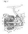
- a spinning reel in accordance with an embodiment of the present invention includes a reel unit 2, a rotor 3, a spool 4, and a handle 1 that is rotatively supported by the reel unit 2.
- the rotor 3 is rotatively supported at the front of the reel unit 2.
- Fishing line is wound around the outer peripheral surface of the spool 4, which is disposed to permit shifting back and forth on the front of the rotor 3.
- the reel unit 2 includes a reel body 2a provided with an opening 2c on its side, a T-shaped rod attachment leg 2b extending diagonally upward to the front from the reel body 2a and formed unitarily therewith, and a lid 2d closing the opening 2c in the reel body 2a.
- the reel body 2a has a space inside, which accommodates a rotor driving mechanism 5 and an oscillating mechanism 6.
- the rotor driving mechanism 5 transmits the rotation of the handle 1 to rotate the rotor 3.
- the oscillating mechanism 6 is for uniformly winding on fishing line by shifting the spool 4 back and forth.
- a circular flange portion 2e is formed with the lid 2d covering the rear of the rotor 3.
- a tubular portion 2f protruding into the rotor 3 is formed at the front of the flange portion 2e.
- a partition wall 2g is formed inside the tubular portion 2f, and tubular spaces are formed on either side of the partition wall 2g.
- the rotor 3 includes a barrel portion 30 the rear end of which is open, and first and second rotor arms 31 and 32, disposed in opposition to one another at the sides of the barrel portion 30.
- the barrel portion 30 and the two rotor arms 31 and 32 are formed unitarily.
- the barrel portion 30 is disposed to the outer peripheral side of the tubular portion 2f of the reel body 2a.
- the open rear portion of the barrel portion 30 is covered by the flange portion 2e.
- a front wall 33 is formed on the front part of the barrel portion 30, and a boss portion 33a is formed in the center of the front wall 33.
- a front portion 12a of the pinion gear 12 and the spool shaft 15 are passed through a through-hole in the boss portion 33a.
- a nut 34 is disposed at the front of the front wall 33, and this nut 34 fastens the rotor 3 to the pinion gear 12 by screwing it to a threaded portion at the front end of the pinion gear 12.
- a bail arm 44 for guiding the fishing line to the spool 4 is provided on the tips of the first and second rotor arms 31 and 32, pivotable between a line-winding position and a line-releasing position.
- a reverse rotation check mechanism 50 for the rotor 3 is provided in the space in front of the partition wall 2g in the barrel portion 30 of the rotor 3.
- This reverse rotation check mechanism 50 has a roller-type one-way clutch 51 and an operating mechanism for switching the one-way clutch 51 between an operating state and a non-operating state.
- the one-way clutch 51 has an outer ring fastened to the reel body 2a and an inner ring mounted non-rotatively to the pinion gear 12.
- the operating mechanism 52 includes an operating lever 53 disposed on the rear of the reel body 2a.
- the one-way clutch 51 can be switched between its two positions by pivoting the operating lever 53.
- the one-way clutch 51 When the one-way clutch 51 is in the operating state, the rotor 3 cannot rotate in reverse, and when it is in the non-operating state, the rotor 3 can rotate in reverse.
- the spool 4 is arranged between the first rotor arm 31 and the second rotor arm 32 of the rotor 3, and is fastened to the front end of the spool shaft 15 with the drag mechanism 60 interposed between the spool shaft 15 and the spool 4.
- the spool 4 includes a bobbin trunk portion 4a circumferentially around fishing line is wound, a skirt portion 4b formed unitarily with the rear of the bobbin trunk portion 4a, and a flange portion 4c attached to the front of the bobbin trunk portion 4a.
- the bobbin trunk portion 4a is a cylindrical member extending to the outer peripheral side of the barrel portion 30 of the rotor 3.
- the skirt portion 4b and the front flange portion 4c extend radially outward perpendicularly from both sides of the bobbin trunk portion 4a.
- the number of windings per layer of fishing line is approximately the same when the fishing line is being wound around the bobbin trunk portion 4a of the spool 4.
- the rotor driving mechanism 5 includes a main gear shaft 10, a main gear 11 and a pinion gear 12.
- the main gear 11 rotates together with the main gear shaft 10, on which the handle 1 is mounted non-rotatively.
- the pinion gear 12 meshes with the main gear 11.
- the pinion gear 12, which is tubular and rotates when the handle is turned, is pierced by the horizontally extending spool shaft 15.
- the middle and the rear of the pinion gear 12 are supported rotatively with ball bearings 14a and 14b by the reel body 2a.
- the rotor 3 is mounted non-rotatively on the front end of the pinion gear 12.
- the oscillating mechanism 6 reciprocates the spool 3 back and forth via the spool shaft 15 when the handle 1 is turned.
- the oscillating mechanism 6 includes the pinion gear 12 serving as a drive gear, a stepped gear unit 13 meshing with the pinion gear 12, and a shifting mechanism 17 including a driven helical gear 16 meshing with the stepped gear unit 13.
- the stepped gear unit 13 is provided for gearing-down the rotation of the pinion gear 12 and transmitting it to the driven gear 16.
- the stepped gear unit 13 is placed in the space behind the partition wall 2g of the tubular portion 2f.
- the stepped gear unit 13 is supported rotatively by the partition wall 2g on a bearing 18 (see Fig. 4 ).
- the stepped gear unit 13 includes two gears of different size, namely a larger-diameter gear 19 meshing with the pinion gear 12, and a smaller-diameter gear 20 formed unitarily with the large diameter gear 19 and meshing with the driven gear 16.
- the smaller-diameter gear 20 is a helical gear arranged concentrically with the larger-diameter gear 19.
- the rotational axis of the stepped gear unit 13 is arranged in parallel to the rotational axes of the pinion gear 12 and the driven gear 16, so that it is easy to ensure a high manufacturing precision.
- the stepped gear unit 13 is arranged in the tubular portion 2f of the reel body 2a, so that it is not necessary to increase the lateral width of the reel body 2, even though deceleration is performed with the stepped gear unit 13 including the larger-diameter gear 19, which is relatively voluminous in the width direction (lateral direction).
- a compact reel can be accomplished.
- the pinion gear 12 has eight teeth, and the larger-diameter gear 19 has sixteen teeth, for example.
- the smaller-diameter gear 20 has five teeth, and the driven gear 16 has fifteen teeth, for example.
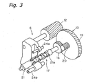
- the shifting mechanism 17 includes a threaded shaft 21, a slider 22, and guide shafts 24a and 24b.
- the threaded shaft 21 is arranged below the spool shaft 15 and mounted to the front end of the driven gear 16.
- the slider 22 moves back and forth along the threaded shaft 21, guided by the two guide shafts 24a and 24b.
- the threaded shaft 21 is arranged in parallel to the spool shaft 15, and is supported rotatively in the reel body 2a.
- Helical intersecting grooves 21a are formed in the outer peripheral portion of the threaded shaft 21.
- the lead angle ⁇ of the grooves 21a is set to 20 to 45°.
- the slider 22 includes a main slider unit 25 and an engaging member 26 accommodated in the main slider unit 25.
- the main slider unit 25 is guided in parallel to the spool shaft 15 by the guide shafts 24a and 24b.
- the engaging member 26 is fitted rotatively within the main slider unit 25, and the front end of the engaging member 26 meshes with the grooves 21a in the threaded shaft 21.
- the stepped gear portion 13 is rotated by the larger-diameter gear 19 meshing with the pinion gear 12, and this rotation is transmitted to the driven gear 16 via the small-rotation gear 20.
- the threaded shaft 21 is rotated at 1/6 of the rotation speed of the pinion gear 12 (rotation speed of the rotor 3).
- the rotation of the threaded shaft 21 causes the slider 22 meshing with the grooves 21a of the threaded shaft 21 to shift in the front-to-rear direction, guided by the guide shafts 24a and 24b.
- the fishing line is guided onto the spool 4 by the bail arm 44 and wound densely around the bobbin trunk portion 4a of the spool 4.
- the fishing line can be wound with high efficiency onto the spool 4.
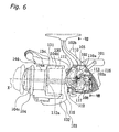
- the oscillating mechanism 106 includes a drive gear 110a formed on a main gear shaft 110 that is formed unitarily with the main gear 111, a stepped gear unit 13 meshing with the driven gear 110a, and a shifting mechanism 117 including a driven gear 116 meshing with the smaller-diameter gear 120 of the stepped gear unit 113.
- the stepped gear unit 113 and the driven gear 116 are supported rotatively in the inner side of the rear wall of the reel body 102a.
- the stepped gear unit 113 and the driven gear 116 are arranged parallel to the main gear shaft 110.
- the larger-diameter gear 119 of the stepped gear unit 113 meshes with the drive gear 110a
- the smaller-diameter gear 120 meshes with the driven gear 116.
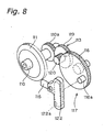
- the shifting mechanism 117 includes a driven gear 116 and a slider 112 disposed in opposition to the driven gear 116.
- a cam pin 116a is formed on the lateral face of the driven gear 116, protruding toward the slider 122.
- the slider 122 can be shifted back and forth in the reel body 102a.
- the slider 122 is fitted non-rotatively on the rear end of the spool shaft 115, and is not shiftable with respect to the spool shaft 115 in the axial direction.
- a vertical cam groove 122a is formed in the lateral face of the slider 122, in opposition to the driven gear 116.
- the cam pin 116a engages with this cam groove 122a.
- the length of the cam groove 122a is a little greater than the rotational diameter of the cam pin 116a.
- the threaded shaft 21 is arranged below the spool shaft 15, but it can also be arranged sideways (laterally) or above it.
- the rotational axes of the smaller-diameter gear 20 of the stepped gear unit 13 and of the reduction gear 16 are configured as parallel helical gears, but they can also be configured so as to transmit a rotational movement between two intersecting or skew rotational axes.
- the two gears can also be configured as bevel gears or crossed helical gears with a relatively simple structure.
- rotational gearing-down is accomplished with a stepped gear unit of simple structure to reciprocate the spool, making it unnecessary to use special gears, and holding down elevation in manufacturing costs.
- the rotational axis of the stepped gear unit is arranged in parallel to the rotational axes of the drive gear and the driven gear, so that it is easy to ensure a high manufacturing precision.
Landscapes
- Life Sciences & Earth Sciences (AREA)
- Environmental Sciences (AREA)
- Animal Husbandry (AREA)
- Biodiversity & Conservation Biology (AREA)
- Spinning Or Twisting Of Yarns (AREA)
- Spinning Methods And Devices For Manufacturing Artificial Fibers (AREA)
Claims (9)
- Un dispositif à va-et-vient de moulinet à tambour (106) destiné à faire aller et venir un tambour (104) d'avant en arrière et réciproquement en coopération avec la rotation d'une poignée (101) fournie sur une unité formant moulinet à tambour (102) sur laquelle un rotor de guidage de ligne de pêche (103) est installé de façon à tourner, la rotation de la poignée (101) étant transmise au rotor (103) par le biais d'une roue d'engrenage (112), le dispositif à va-et-vient de moulinet à tambour (106) comprenant :une roue principale (111) destinée à tourner conjointement avec la rotation de la poignée (101) ;une roue menante (110a) destinée à tourner en coopération avec la rotation de la poignée (101) ;une unité formant roue à étages (113) incluant une roue de plus grand diamètre (119) qui a plus de dents que la roue menante (110a) et qui s'engrène dans la roue menante (110a), et une roue de plus petit diamètre (120) disposée de façon concentrique avec la roue de plus grand diamètre (119) et qui tourne d'un seul bloc avec la roue de plus grand diamètre (119) ; etun moyen de décalage (117) qui a une roue menée (116) qui s'engrène dans la roue de plus petit diamètre (120) et une pièce coulissante (122) qui est disposée face à la roue menée (116) et couplée de manière à ce qu'elle ne puisse pas se déplacer de façon axiale à un arbre de tambour (115) sur lequel est attaché le tambour (104), le moyen de décalage (117) étant destiné à faire aller et venir le tambour (104) grâce à la rotation de la roue menée (116), la roue menée (116) ayant plus de dents que la roue de plus petit diamètre (120),caractérisé en ce que la roue menante (110a) est disposée sur un côté opposé de la roue d'engrenage (112) par rapport à la roue principale (111).
- Le dispositif à va-et-vient de moulinet à tambour (106) tel qu'énoncé dans la revendication 1, dans lequel :le rotor (103) a une portion formant barillet (130) et une paire de bras de rotor (131, 132) qui s'étendent vers l'avant depuis une extrémité arrière de la portion formant barillet (130), et l'unité formant moulinet (102) a une portion tubulaire qui s'étend intérieurement jusque dans la portion formant barillet (130) ; etl'unité formant roue à étages (113) est disposée intérieurement dans la portion tubulaire.
- Le dispositif à va-et-vient de moulinet à tambour (106) tel qu'énoncé dans la revendication 1 ou la revendication 2, dans lequel :ladite roue menée (116) inclut un doigt de came (116a) qui fait saillie depuis une face latérale de ladite roue menée (116) ; etladite pièce coulissante (122) est installée de façon à aller et venir sur l'unité formant moulinet (102) et a une rainure de came (122a) sur une face latérale de ladite pièce coulissante (122) qui est opposée à ladite roue menée (116) de telle sorte que ledit doigt de came (116a) s'engage dans ladite rainure de came (122a), ladite rainure de came (122a) s'étendant dans une direction qui coupe une direction dans laquelle le tambour (104) se déplace.
- Le dispositif à va-et-vient de moulinet à tambour (106) tel qu'énoncé dans la revendication 3, dans lequel
une longueur de ladite rainure de came (122a) est supérieure à un diamètre d'un cercle le long duquel ledit doigt de came (116a) pivote. - Le dispositif à va-et-vient de moulinet à tambour (106) tel qu'énoncé dans n'importe lesquelles des revendications 1 à 4, dans lequel :ladite unité formant roue à étages (113) et ladite roue menée (116) sont toutes deux soutenues par l'unité formant moulinet (102).
- Le dispositif à va-et-vient de moulinet à tambour (106) tel qu'énoncé dans n'importe quelle revendication précédente, dans lequel
ladite roue de plus petit diamètre (120) est disposée plus près de ladite pièce coulissante (122) que ladite roue de plus grand diamètre (119). - Le dispositif à va-et-vient de moulinet à tambour (106) tel qu'énoncé dans n'importe quelle revendication précédente, dans lequel :ladite roue menante (110a) est fournie sur un arbre de roue principale (110) qui est monté de façon à tourner dans l'unité formant moulinet (102) de manière à tourner d'un seul bloc avec la poignée (101) ; etl'arbre de tambour (115), lequel est monté de manière à ce qu'il puisse se déplacer de façon axiale dans l'unité formant moulinet (102) et sur l'extrémité avant duquel le tambour (104) est attaché, est installé de manière à ce qu'il ne puisse pas se déplacer de façon axiale sur ladite pièce coulissante (122).
- Un moulinet à tambour, comprenant :une unité formant moulinet (102) qui a un mécanisme à va-et-vient (106), tel que revendiqué dans n'importe quelle revendication précédente ;un rotor (103) soutenu de façon à tourner au niveau d'une portion avant de ladite unité formant moulinet (102) ;une poignée (101) soutenue de façon à tourner par ladite unité formant moulinet (102), la rotation de ladite poignée (101) étant transmise audit rotor (103) par le biais d'une roue d'engrenage (112) ; etun tambour (104) disposé sur une portion avant dudit rotor (103) de manière à pouvoir être décalé dans une direction avant-arrière par l'intermédiaire dudit mécanisme à va-et-vient (106).
- Le moulinet à tambour tel qu'énoncé dans la revendication 8, dans lequel :ladite unité formant moulinet (102) a un corps de moulinet (102a) qui a une ouverture sur son côté, et un élément formant couvercle pour fermer ladite ouverture, et un arbre de poignée (110) autour duquel ladite poignée (101) tourne est soutenu à la fois par ledit corps de moulinet (102) et ledit élément formant couvercle.
Applications Claiming Priority (3)
| Application Number | Priority Date | Filing Date | Title |
|---|---|---|---|
| JP2000145964 | 2000-05-18 | ||
| JP2000145964A JP2001321041A (ja) | 2000-05-18 | 2000-05-18 | スピニングリールの往復移動装置 |
| EP01304292A EP1155613B1 (fr) | 2000-05-18 | 2001-05-14 | Mécanisme d'oscillation pour moulinet de pêche |
Related Parent Applications (1)
| Application Number | Title | Priority Date | Filing Date |
|---|---|---|---|
| EP01304292A Division EP1155613B1 (fr) | 2000-05-18 | 2001-05-14 | Mécanisme d'oscillation pour moulinet de pêche |
Publications (3)
| Publication Number | Publication Date |
|---|---|
| EP1525794A2 EP1525794A2 (fr) | 2005-04-27 |
| EP1525794A3 EP1525794A3 (fr) | 2005-05-11 |
| EP1525794B1 true EP1525794B1 (fr) | 2008-03-26 |
Family
ID=18652398
Family Applications (2)
| Application Number | Title | Priority Date | Filing Date |
|---|---|---|---|
| EP01304292A Expired - Lifetime EP1155613B1 (fr) | 2000-05-18 | 2001-05-14 | Mécanisme d'oscillation pour moulinet de pêche |
| EP05000794A Expired - Lifetime EP1525794B1 (fr) | 2000-05-18 | 2001-05-14 | Mécanisme d'oscillation pour moulinet de pêche |
Family Applications Before (1)
| Application Number | Title | Priority Date | Filing Date |
|---|---|---|---|
| EP01304292A Expired - Lifetime EP1155613B1 (fr) | 2000-05-18 | 2001-05-14 | Mécanisme d'oscillation pour moulinet de pêche |
Country Status (10)
| Country | Link |
|---|---|
| US (2) | US6412721B2 (fr) |
| EP (2) | EP1155613B1 (fr) |
| JP (1) | JP2001321041A (fr) |
| KR (1) | KR100722535B1 (fr) |
| CN (2) | CN100377643C (fr) |
| AT (2) | ATE320708T1 (fr) |
| DE (2) | DE60118116T2 (fr) |
| MY (1) | MY124891A (fr) |
| SG (1) | SG98445A1 (fr) |
| TW (1) | TW588581U (fr) |
Families Citing this family (29)
| Publication number | Priority date | Publication date | Assignee | Title |
|---|---|---|---|---|
| JP2002101792A (ja) * | 2000-09-18 | 2002-04-09 | Shimano Singapore Pte Ltd | スピニングリールの往復移動機構 |
| US6682007B2 (en) * | 2001-03-15 | 2004-01-27 | Kabushiki Kaisha Johshuya | Spinning reel having improved spool oscillating mechanism |
| JP2003079291A (ja) * | 2001-09-12 | 2003-03-18 | Shimano Inc | スピニングリールの往復移動機構 |
| JP2003225040A (ja) | 2002-02-04 | 2003-08-12 | Shimano Inc | 釣り用リールの動力伝達装置 |
| JP3926198B2 (ja) * | 2002-04-19 | 2007-06-06 | 株式会社シマノ | スピニングリールの螺軸取付構造 |
| US6626385B1 (en) * | 2002-08-01 | 2003-09-30 | Daiwa Seiko, Inc. | Spinning reel for fishing |
| JP2004081077A (ja) * | 2002-08-26 | 2004-03-18 | Shimano Inc | スピニングリールの往復移動装置 |
| US7118059B2 (en) | 2003-01-29 | 2006-10-10 | Shimano Inc. | Reel unit for spinning reel |
| TWI315185B (en) | 2003-05-15 | 2009-10-01 | Shimano Kk | Drag adjustment knob for a spinning reel |
| JP4299180B2 (ja) * | 2003-08-27 | 2009-07-22 | 株式会社シマノ | スピニングリールの往復移動装置 |
| US7413175B2 (en) | 2005-03-31 | 2008-08-19 | Xerox Corporation | Automated cover-driven workflows for manufacturing books in a production environment |
| GB0608383D0 (en) * | 2006-04-27 | 2006-06-07 | Fox Int Group Ltd | A fixed spool fishing reel |
| MY162139A (en) * | 2007-09-14 | 2017-05-31 | Shimano Kk | Spining reel |
| US8176737B2 (en) * | 2008-07-31 | 2012-05-15 | Caterpillar Inc. | Exhaust system having 3-way valve |
| JP5143757B2 (ja) * | 2009-01-26 | 2013-02-13 | 株式会社シマノ | 釣り用リールの螺軸及びそれを用いた釣り用リールの往復移動機構 |
| CA2792801C (fr) * | 2010-03-11 | 2017-01-10 | Advanced Catheter Therapies, Inc. | Dispositif d'atherectomie |
| JP6140956B2 (ja) * | 2012-09-18 | 2017-06-07 | 株式会社シマノ | スピニングリール |
| CN103004713B (zh) * | 2012-11-30 | 2014-05-07 | 宁波海宝渔具有限公司 | 一种齿轮传动无间隙的钓鱼用纺车式渔线轮 |
| KR102312398B1 (ko) * | 2013-10-01 | 2021-10-13 | 가부시키가이샤 시마노 | 낚시용 릴의 왕복 이동 기구 |
| CN103875621B (zh) * | 2013-10-21 | 2017-06-16 | 东莞市凯特渔具制造有限公司 | 纺车式渔线轮凸轮传动机构 |
| JP6656813B2 (ja) * | 2015-03-10 | 2020-03-04 | 株式会社シマノ | 釣り用リールの往復移動機構及び釣り用リール |
| WO2017104837A1 (fr) * | 2015-12-18 | 2017-06-22 | グローブライド株式会社 | Moulinet de pêche |
| CN107873662A (zh) * | 2016-09-30 | 2018-04-06 | 宁波海宝渔具有限公司 | 可变速的钓鱼用两轴式卷线器 |
| CN108990931A (zh) * | 2017-06-07 | 2018-12-14 | 纯钓日本公司 | 钓鱼用纺车式渔轮 |
| JP6908447B2 (ja) * | 2017-06-27 | 2021-07-28 | 株式会社シマノ | 釣り用リールの往復移動機構 |
| JP7046743B2 (ja) * | 2018-07-06 | 2022-04-04 | 株式会社シマノ | スピニングリール |
| TWI737994B (zh) * | 2019-05-14 | 2021-09-01 | 宏正自動科技股份有限公司 | 減速機構及其捲線裝置 |
| CN110192545B (zh) * | 2019-06-10 | 2024-06-18 | 慈溪市永杰精工渔具有限公司 | 一种渔线轮往复机构及应用该往复机构的纺车式鱼线轮 |
| JP7385525B2 (ja) * | 2020-05-18 | 2023-11-22 | 株式会社シマノ | スピニングリール |
Family Cites Families (16)
| Publication number | Priority date | Publication date | Assignee | Title |
|---|---|---|---|---|
| US583913A (en) * | 1897-06-08 | Fishing-reel | ||
| US982305A (en) * | 1908-07-13 | 1911-01-24 | William Shakespeare Jr Company | Fishing-reel. |
| CH258217A (fr) * | 1945-10-05 | 1948-11-30 | Huillet Jean | Moulinet pour la pêche au lancer. |
| GB645978A (en) * | 1948-08-03 | 1950-11-15 | Carpano & Pons | An improved reel for fly fishing |
| US2686016A (en) * | 1949-10-20 | 1954-08-10 | Rudolph R Kilian | Fishing reel |
| US2726052A (en) * | 1952-12-19 | 1955-12-06 | Carpano & Pons | Fishing reel |
| US3055607A (en) * | 1961-05-19 | 1962-09-25 | Angelgerate Manufaktur D A M H | Fishing reel with spool transversing mechanism |
| US4026493A (en) * | 1976-07-16 | 1977-05-31 | Anderson William C | Hydraulic drive for fishing reel having variable takeup ratio |
| JPH0774327B2 (ja) | 1987-02-14 | 1995-08-09 | 日東電工株式会社 | 紫外線硬化型シリコーン系剥離剤 |
| US5316239A (en) * | 1990-07-10 | 1994-05-31 | Shimano Inc. | Spinning reel with oscillating mechanism |
| US5232181A (en) * | 1991-05-24 | 1993-08-03 | Olympic Co., Ltd. | Spinning reel for fishing |
| JPH0521663U (ja) * | 1991-09-09 | 1993-03-23 | 株式会社シマノ | スピニングリールのオシレーテイング機構 |
| JP3199351B2 (ja) * | 1995-07-04 | 2001-08-20 | ダイワ精工株式会社 | スピニングリール |
| JP3292366B2 (ja) * | 1996-09-09 | 2002-06-17 | ダイワ精工株式会社 | 魚釣用スピニングリール |
| US5878523A (en) * | 1997-10-30 | 1999-03-09 | Wenzel; Stephen R. | Motorized reeling assembly with automatic cut-off |
| US6264125B1 (en) * | 1999-12-09 | 2001-07-24 | Brunswick Corporation | Asymmetric oscillation mechanism for a spinning reel |
-
2000
- 2000-05-18 JP JP2000145964A patent/JP2001321041A/ja active Pending
-
2001
- 2001-04-16 TW TW091212769U patent/TW588581U/zh not_active IP Right Cessation
- 2001-05-09 KR KR1020010025263A patent/KR100722535B1/ko not_active IP Right Cessation
- 2001-05-14 AT AT01304292T patent/ATE320708T1/de not_active IP Right Cessation
- 2001-05-14 EP EP01304292A patent/EP1155613B1/fr not_active Expired - Lifetime
- 2001-05-14 US US09/853,776 patent/US6412721B2/en not_active Expired - Fee Related
- 2001-05-14 SG SG200102871A patent/SG98445A1/en unknown
- 2001-05-14 DE DE60118116T patent/DE60118116T2/de not_active Expired - Lifetime
- 2001-05-14 DE DE60133427T patent/DE60133427T2/de not_active Expired - Lifetime
- 2001-05-14 EP EP05000794A patent/EP1525794B1/fr not_active Expired - Lifetime
- 2001-05-14 AT AT05000794T patent/ATE390048T1/de not_active IP Right Cessation
- 2001-05-16 MY MYPI20012314 patent/MY124891A/en unknown
- 2001-05-18 CN CNB2005100044852A patent/CN100377643C/zh not_active Expired - Fee Related
- 2001-05-18 CN CNB011196149A patent/CN1193660C/zh not_active Expired - Fee Related
-
2002
- 2002-05-20 US US10/147,850 patent/US6484956B2/en not_active Expired - Fee Related
Also Published As
| Publication number | Publication date |
|---|---|
| CN1193660C (zh) | 2005-03-23 |
| TW588581U (en) | 2004-05-21 |
| DE60118116T2 (de) | 2006-10-26 |
| EP1155613B1 (fr) | 2006-03-22 |
| US20010042804A1 (en) | 2001-11-22 |
| CN100377643C (zh) | 2008-04-02 |
| ATE320708T1 (de) | 2006-04-15 |
| EP1525794A3 (fr) | 2005-05-11 |
| CN1631129A (zh) | 2005-06-29 |
| CN1324565A (zh) | 2001-12-05 |
| EP1155613A1 (fr) | 2001-11-21 |
| JP2001321041A (ja) | 2001-11-20 |
| SG98445A1 (en) | 2003-09-19 |
| EP1525794A2 (fr) | 2005-04-27 |
| US6484956B2 (en) | 2002-11-26 |
| KR20010105169A (ko) | 2001-11-28 |
| DE60133427D1 (de) | 2008-05-08 |
| US20020134873A1 (en) | 2002-09-26 |
| KR100722535B1 (ko) | 2007-05-28 |
| DE60133427T2 (de) | 2009-04-23 |
| US6412721B2 (en) | 2002-07-02 |
| ATE390048T1 (de) | 2008-04-15 |
| DE60118116D1 (de) | 2006-05-11 |
| MY124891A (en) | 2006-07-31 |
Similar Documents
| Publication | Publication Date | Title |
|---|---|---|
| EP1525794B1 (fr) | Mécanisme d'oscillation pour moulinet de pêche | |
| EP1169919B1 (fr) | Mécanisme d'oscillation pour moulinet de pêche | |
| EP1810566A1 (fr) | Structure de montage d'engrenage pour moulinet de pêche | |
| US20120128414A1 (en) | Fishing reel gear attachment structure | |
| EP1332670B1 (fr) | Transmission de puissance pour moulinet de pêche | |
| EP0054425B1 (fr) | Moulinet de pêche | |
| EP1082899B1 (fr) | Moulinet de pêche comportant un dispositif de transmission de rotation | |
| JP2003225040A5 (fr) | ||
| US5388777A (en) | Spinning reel with improved control structure of stopper mechanism | |
| JPH09140302A (ja) | 魚釣用両軸受型リール | |
| JP2005253477A (ja) | スピニングリールの往復移動装置 | |
| JP4047534B2 (ja) | 魚釣用スピニングリール | |
| JP2002125538A (ja) | スピニングリールの往復移動装置 | |
| JP4023802B2 (ja) | 魚釣用リール | |
| JP3086776B2 (ja) | 魚釣用電動リール | |
| JPH11262347A (ja) | 両軸受型リール | |
| KR920008580Y1 (ko) | 낚시용 스피닝릴의 스풀 왕복 이동장치 | |
| JPH07255335A (ja) | 釣用後方ドラグ型スピニングリールのスプール往復装置 | |
| JPH0582280U (ja) | スピニングリール |
Legal Events
| Date | Code | Title | Description |
|---|---|---|---|
| PUAI | Public reference made under article 153(3) epc to a published international application that has entered the european phase |
Free format text: ORIGINAL CODE: 0009012 |
|
| PUAL | Search report despatched |
Free format text: ORIGINAL CODE: 0009013 |
|
| AC | Divisional application: reference to earlier application |
Ref document number: 1155613 Country of ref document: EP Kind code of ref document: P |
|
| AK | Designated contracting states |
Kind code of ref document: A2 Designated state(s): AT BE CH CY DE DK ES FI FR GB GR IE IT LI LU MC NL PT SE TR |
|
| AK | Designated contracting states |
Kind code of ref document: A3 Designated state(s): AT BE CH CY DE DK ES FI FR GB GR IE IT LI LU MC NL PT SE TR |
|
| RIN1 | Information on inventor provided before grant (corrected) |
Inventor name: SUGAWARA, KENICHIC/O SHIMANO INC Inventor name: KAWABE, YUZO |
|
| 17P | Request for examination filed |
Effective date: 20050607 |
|
| AKX | Designation fees paid |
Designated state(s): AT BE CH CY DE DK ES FI FR GB GR IE IT LI LU MC NL PT SE TR |
|
| RAP1 | Party data changed (applicant data changed or rights of an application transferred) |
Owner name: SHIMANO INC. |
|
| GRAP | Despatch of communication of intention to grant a patent |
Free format text: ORIGINAL CODE: EPIDOSNIGR1 |
|
| GRAS | Grant fee paid |
Free format text: ORIGINAL CODE: EPIDOSNIGR3 |
|
| GRAA | (expected) grant |
Free format text: ORIGINAL CODE: 0009210 |
|
| AC | Divisional application: reference to earlier application |
Ref document number: 1155613 Country of ref document: EP Kind code of ref document: P |
|
| AK | Designated contracting states |
Kind code of ref document: B1 Designated state(s): AT BE CH CY DE DK ES FI FR GB GR IE IT LI LU MC NL PT SE TR |
|
| REG | Reference to a national code |
Ref country code: GB Ref legal event code: FG4D |
|
| REG | Reference to a national code |
Ref country code: CH Ref legal event code: EP Ref country code: IE Ref legal event code: FG4D |
|
| REF | Corresponds to: |
Ref document number: 60133427 Country of ref document: DE Date of ref document: 20080508 Kind code of ref document: P |
|
| PG25 | Lapsed in a contracting state [announced via postgrant information from national office to epo] |
Ref country code: FI Free format text: LAPSE BECAUSE OF FAILURE TO SUBMIT A TRANSLATION OF THE DESCRIPTION OR TO PAY THE FEE WITHIN THE PRESCRIBED TIME-LIMIT Effective date: 20080326 |
|
| PG25 | Lapsed in a contracting state [announced via postgrant information from national office to epo] |
Ref country code: AT Free format text: LAPSE BECAUSE OF FAILURE TO SUBMIT A TRANSLATION OF THE DESCRIPTION OR TO PAY THE FEE WITHIN THE PRESCRIBED TIME-LIMIT Effective date: 20080326 |
|
| NLV1 | Nl: lapsed or annulled due to failure to fulfill the requirements of art. 29p and 29m of the patents act | ||
| PG25 | Lapsed in a contracting state [announced via postgrant information from national office to epo] |
Ref country code: BE Free format text: LAPSE BECAUSE OF FAILURE TO SUBMIT A TRANSLATION OF THE DESCRIPTION OR TO PAY THE FEE WITHIN THE PRESCRIBED TIME-LIMIT Effective date: 20080326 |
|
| PG25 | Lapsed in a contracting state [announced via postgrant information from national office to epo] |
Ref country code: PT Free format text: LAPSE BECAUSE OF FAILURE TO SUBMIT A TRANSLATION OF THE DESCRIPTION OR TO PAY THE FEE WITHIN THE PRESCRIBED TIME-LIMIT Effective date: 20080901 Ref country code: ES Free format text: LAPSE BECAUSE OF FAILURE TO SUBMIT A TRANSLATION OF THE DESCRIPTION OR TO PAY THE FEE WITHIN THE PRESCRIBED TIME-LIMIT Effective date: 20080707 Ref country code: SE Free format text: LAPSE BECAUSE OF FAILURE TO SUBMIT A TRANSLATION OF THE DESCRIPTION OR TO PAY THE FEE WITHIN THE PRESCRIBED TIME-LIMIT Effective date: 20080626 |
|
| PG25 | Lapsed in a contracting state [announced via postgrant information from national office to epo] |
Ref country code: NL Free format text: LAPSE BECAUSE OF FAILURE TO SUBMIT A TRANSLATION OF THE DESCRIPTION OR TO PAY THE FEE WITHIN THE PRESCRIBED TIME-LIMIT Effective date: 20080326 |
|
| ET | Fr: translation filed | ||
| PG25 | Lapsed in a contracting state [announced via postgrant information from national office to epo] |
Ref country code: MC Free format text: LAPSE BECAUSE OF NON-PAYMENT OF DUE FEES Effective date: 20080531 |
|
| REG | Reference to a national code |
Ref country code: CH Ref legal event code: PL |
|
| PG25 | Lapsed in a contracting state [announced via postgrant information from national office to epo] |
Ref country code: DK Free format text: LAPSE BECAUSE OF FAILURE TO SUBMIT A TRANSLATION OF THE DESCRIPTION OR TO PAY THE FEE WITHIN THE PRESCRIBED TIME-LIMIT Effective date: 20080326 Ref country code: LI Free format text: LAPSE BECAUSE OF NON-PAYMENT OF DUE FEES Effective date: 20080531 Ref country code: CH Free format text: LAPSE BECAUSE OF NON-PAYMENT OF DUE FEES Effective date: 20080531 |
|
| PLBE | No opposition filed within time limit |
Free format text: ORIGINAL CODE: 0009261 |
|
| STAA | Information on the status of an ep patent application or granted ep patent |
Free format text: STATUS: NO OPPOSITION FILED WITHIN TIME LIMIT |
|
| 26N | No opposition filed |
Effective date: 20081230 |
|
| PG25 | Lapsed in a contracting state [announced via postgrant information from national office to epo] |
Ref country code: IE Free format text: LAPSE BECAUSE OF NON-PAYMENT OF DUE FEES Effective date: 20080514 |
|
| PG25 | Lapsed in a contracting state [announced via postgrant information from national office to epo] |
Ref country code: IT Free format text: LAPSE BECAUSE OF FAILURE TO SUBMIT A TRANSLATION OF THE DESCRIPTION OR TO PAY THE FEE WITHIN THE PRESCRIBED TIME-LIMIT Effective date: 20080326 |
|
| PG25 | Lapsed in a contracting state [announced via postgrant information from national office to epo] |
Ref country code: CY Free format text: LAPSE BECAUSE OF FAILURE TO SUBMIT A TRANSLATION OF THE DESCRIPTION OR TO PAY THE FEE WITHIN THE PRESCRIBED TIME-LIMIT Effective date: 20080326 |
|
| PG25 | Lapsed in a contracting state [announced via postgrant information from national office to epo] |
Ref country code: LU Free format text: LAPSE BECAUSE OF NON-PAYMENT OF DUE FEES Effective date: 20080514 |
|
| PG25 | Lapsed in a contracting state [announced via postgrant information from national office to epo] |
Ref country code: TR Free format text: LAPSE BECAUSE OF FAILURE TO SUBMIT A TRANSLATION OF THE DESCRIPTION OR TO PAY THE FEE WITHIN THE PRESCRIBED TIME-LIMIT Effective date: 20080326 |
|
| PG25 | Lapsed in a contracting state [announced via postgrant information from national office to epo] |
Ref country code: GR Free format text: LAPSE BECAUSE OF FAILURE TO SUBMIT A TRANSLATION OF THE DESCRIPTION OR TO PAY THE FEE WITHIN THE PRESCRIBED TIME-LIMIT Effective date: 20080627 |
|
| PGFP | Annual fee paid to national office [announced via postgrant information from national office to epo] |
Ref country code: DE Payment date: 20130515 Year of fee payment: 13 Ref country code: GB Payment date: 20130508 Year of fee payment: 13 |
|
| PGFP | Annual fee paid to national office [announced via postgrant information from national office to epo] |
Ref country code: FR Payment date: 20130531 Year of fee payment: 13 |
|
| REG | Reference to a national code |
Ref country code: DE Ref legal event code: R119 Ref document number: 60133427 Country of ref document: DE |
|
| GBPC | Gb: european patent ceased through non-payment of renewal fee |
Effective date: 20140514 |
|
| REG | Reference to a national code |
Ref country code: DE Ref legal event code: R119 Ref document number: 60133427 Country of ref document: DE Effective date: 20141202 |
|
| REG | Reference to a national code |
Ref country code: FR Ref legal event code: ST Effective date: 20150130 |
|
| PG25 | Lapsed in a contracting state [announced via postgrant information from national office to epo] |
Ref country code: DE Free format text: LAPSE BECAUSE OF NON-PAYMENT OF DUE FEES Effective date: 20141202 |
|
| PG25 | Lapsed in a contracting state [announced via postgrant information from national office to epo] |
Ref country code: FR Free format text: LAPSE BECAUSE OF NON-PAYMENT OF DUE FEES Effective date: 20140602 Ref country code: GB Free format text: LAPSE BECAUSE OF NON-PAYMENT OF DUE FEES Effective date: 20140514 |