EP1525794B1 - Spinning-reel reciprocating device - Google Patents
Spinning-reel reciprocating device Download PDFInfo
- Publication number
- EP1525794B1 EP1525794B1 EP05000794A EP05000794A EP1525794B1 EP 1525794 B1 EP1525794 B1 EP 1525794B1 EP 05000794 A EP05000794 A EP 05000794A EP 05000794 A EP05000794 A EP 05000794A EP 1525794 B1 EP1525794 B1 EP 1525794B1
- Authority
- EP
- European Patent Office
- Prior art keywords
- gear
- reel
- spool
- unit
- handle
- Prior art date
- Legal status (The legal status is an assumption and is not a legal conclusion. Google has not performed a legal analysis and makes no representation as to the accuracy of the status listed.)
- Expired - Lifetime
Links
Images


Classifications
-
- A—HUMAN NECESSITIES
- A01—AGRICULTURE; FORESTRY; ANIMAL HUSBANDRY; HUNTING; TRAPPING; FISHING
- A01K—ANIMAL HUSBANDRY; CARE OF BIRDS, FISHES, INSECTS; FISHING; REARING OR BREEDING ANIMALS, NOT OTHERWISE PROVIDED FOR; NEW BREEDS OF ANIMALS
- A01K89/00—Reels
- A01K89/01—Reels with pick-up, i.e. with the guiding member rotating and the spool not rotating during normal retrieval of the line
- A01K89/0114—Reciprocating mechanisms
Definitions
- the present invention relates to reciprocating devices, and in particular to spinning-reel reciprocating devices that pump the spool back and forth in cooperation with rotation of the handle.
- Spinning-reel transverse-cam oscillating mechanisms include a driven gear meshing with a pinion gear, a threaded shaft, and a slider meshing with the threaded shaft.
- the threaded shaft is mounted to the front end of the driven gear and arranged in parallel with the spool shaft.
- the spool shaft is mounted to the slider and is axially immobile with respect to the slider.
- JP H11-86A (1999) discloses an oscillating mechanism in which the amount that the spool is shifted back and forth per rotation of the handle is decreased, so that the fishing line can be wound densely onto the spool.
- the oscillating mechanism is provided with: a linking shaft disposed along an axis skew with the pinion gear so as to orient toward the threaded shaft; a screw gear fixed to one end of the linking shaft and meshing with the pinion gear; a worm gear fixed to the other end of the linking shaft; and a worm wheel fitted non-rotatably to the threaded shaft and meshing with the worm gear.
- the linking shaft, linking the pinion gear and the threaded shaft is arranged diagonally in the reel unit along an axis skew with the pinion gear to serve to make the reel unit thinner.
- the above-noted conventional configuration utilizes the worm gear, and the worm wheel that meshes with the worm gear, for gearing-down in order to wind densely, meaning that special gears difficult to machine are used, which makes manufacturing costs high.
- the linking shaft is disposed diagonally to link the pinion gear and the threaded gear, the linking shaft and the threaded shaft have to be established in different directions, and the bearings that support them also have to be established in the different directions. Establishing two types of bearings in the different directions makes guaranteeing machining precision difficult, elevating machining costs.
- An object of the present invention is in holding down manufacturing costs and readily ensuring manufacturing precision in a reciprocating mechanism that enables dense winding.
- a spinning reel reciprocating device for shifting a spool back and forth when turning a handle attached to a reel unit of the spinning reel to which a rotor, onto which fishing line is guided, is mounted rotatively includes a drive gear, a stepped gear unit and a shifting means.
- the drive gear rotates when the handle is rotated.
- the stepped gear unit includes a larger-diameter gear meshing with the drive gear and a smaller-diameter gear arranged concentrically to the larger-diameter gear and rotating together with the larger-diameter gear.
- the shifting means which has a driven gear meshing with the smaller-diameter gear, is for shifting the spool back and forth by rotating the driven gear.
- the drive gear is disposed on an opposite side of the pinion gear than the main gear.
- the drive gear rotates as a result of turning the handle.
- the drive gear rotates, its rotation is transmitted to the larger-diameter gear of the stepped gear unit, and the smaller-diameter gear rotates together with the larger-diameter gear.
- the smaller-diameter gear rotates, its rotation is transmitted to the driven gear, and the spool is shifted back and forth with the shifting means.
- rotation deceleration and the shifting of the spool is accomplished with a stepped gear unit of simple structure, so that it is not necessary to use any special gears, and the manufacturing costs can be kept down.
- the rotational axis of the stepped gear unit is arranged in parallel to the rotational axes of the drive gear and the driven gear, so that it is easy to ensure a high manufacturing precision.
- the drive gear is a pinion gear rotating around a spool shaft that can be shifted back and forth with respect to the reel unit, the spool being mounted to the tip of the spool shaft.
- the shifting means includes (i) a threaded shaft arranged in parallel to the spool shaft, the driven gear being attached non-rotatively to the threaded shaft, and intersecting helical grooves being formed in a surface of the threaded shaft, and (ii) a sliding element that can be shifted back and forth with respect to the reel unit, and has an engager engaging with the helical grooves.
- the spool shaft is mounted to the sliding element and cannot be shifted back and forth with respect to the sliding element.
- the rotational axis of the pinion gear which is the drive gear and extends horizontally, as well as the rotational axis of the stepped gear unit, and the threaded shaft are arranged in parallel, so that the spinning reel can be made flat by arranging them vertically one above the other.
- a compact vertical size can be achieved by arranging them horizontally next to one another.
- the rotor in a reciprocating device as in the first aspect, includes a barrel portion, and a pair of rotor arms extending frontward from a rear end of the barrel portion.
- the reel unit has a tubular portion extending into the barrel portion., and the stepped gear unit is arranged inside the tubular portion. With this configuration, the relatively large diameter stepped gear unit is arranged in the tubular portion extending into the barrel portion of the rotor, so that using space efficiently, the reel can be made flatter.
- the drive gear is provided on a main gear shaft mounted rotatively in the reel unit, and rotates together with the handle.
- the shifting means includes a cam pin protruding from a lateral face of the driven gear, and a sliding element that can be shifted back and forth with respect to the reel unit and has a cam groove engaging the cam pin.
- the spool is attached to the front end of a spool shaft, which can be shifted back and forth with respect to the reel unit, and which is mounted to the sliding element with respect to which it cannot be shifted back and forth.
- the number of teeth on the drive gear is smaller than the number of teeth on the larger-diameter gear. This configuration achieves gearing-down between the shifting gear and the larger-diameter gear.
- the number of teeth on the driven gear is larger than the number of teeth on the smaller-diameter gear. With this configuration, deceleration between the driven gear and the smaller-diameter gear is achieved, and a large gear-down ratio is attained.
- a spinning reel in accordance with an embodiment of the present invention includes a reel unit 2, a rotor 3, a spool 4, and a handle 1 that is rotatively supported by the reel unit 2.
- the rotor 3 is rotatively supported at the front of the reel unit 2.
- Fishing line is wound around the outer peripheral surface of the spool 4, which is disposed to permit shifting back and forth on the front of the rotor 3.
- the reel unit 2 includes a reel body 2a provided with an opening 2c on its side, a T-shaped rod attachment leg 2b extending diagonally upward to the front from the reel body 2a and formed unitarily therewith, and a lid 2d closing the opening 2c in the reel body 2a.
- the reel body 2a has a space inside, which accommodates a rotor driving mechanism 5 and an oscillating mechanism 6.
- the rotor driving mechanism 5 transmits the rotation of the handle 1 to rotate the rotor 3.
- the oscillating mechanism 6 is for uniformly winding on fishing line by shifting the spool 4 back and forth.
- a circular flange portion 2e is formed with the lid 2d covering the rear of the rotor 3.
- a tubular portion 2f protruding into the rotor 3 is formed at the front of the flange portion 2e.
- a partition wall 2g is formed inside the tubular portion 2f, and tubular spaces are formed on either side of the partition wall 2g.
- the rotor 3 includes a barrel portion 30 the rear end of which is open, and first and second rotor arms 31 and 32, disposed in opposition to one another at the sides of the barrel portion 30.
- the barrel portion 30 and the two rotor arms 31 and 32 are formed unitarily.
- the barrel portion 30 is disposed to the outer peripheral side of the tubular portion 2f of the reel body 2a.
- the open rear portion of the barrel portion 30 is covered by the flange portion 2e.
- a front wall 33 is formed on the front part of the barrel portion 30, and a boss portion 33a is formed in the center of the front wall 33.
- a front portion 12a of the pinion gear 12 and the spool shaft 15 are passed through a through-hole in the boss portion 33a.
- a nut 34 is disposed at the front of the front wall 33, and this nut 34 fastens the rotor 3 to the pinion gear 12 by screwing it to a threaded portion at the front end of the pinion gear 12.
- a bail arm 44 for guiding the fishing line to the spool 4 is provided on the tips of the first and second rotor arms 31 and 32, pivotable between a line-winding position and a line-releasing position.
- a reverse rotation check mechanism 50 for the rotor 3 is provided in the space in front of the partition wall 2g in the barrel portion 30 of the rotor 3.
- This reverse rotation check mechanism 50 has a roller-type one-way clutch 51 and an operating mechanism for switching the one-way clutch 51 between an operating state and a non-operating state.
- the one-way clutch 51 has an outer ring fastened to the reel body 2a and an inner ring mounted non-rotatively to the pinion gear 12.
- the operating mechanism 52 includes an operating lever 53 disposed on the rear of the reel body 2a.
- the one-way clutch 51 can be switched between its two positions by pivoting the operating lever 53.
- the one-way clutch 51 When the one-way clutch 51 is in the operating state, the rotor 3 cannot rotate in reverse, and when it is in the non-operating state, the rotor 3 can rotate in reverse.
- the spool 4 is arranged between the first rotor arm 31 and the second rotor arm 32 of the rotor 3, and is fastened to the front end of the spool shaft 15 with the drag mechanism 60 interposed between the spool shaft 15 and the spool 4.
- the spool 4 includes a bobbin trunk portion 4a circumferentially around fishing line is wound, a skirt portion 4b formed unitarily with the rear of the bobbin trunk portion 4a, and a flange portion 4c attached to the front of the bobbin trunk portion 4a.
- the bobbin trunk portion 4a is a cylindrical member extending to the outer peripheral side of the barrel portion 30 of the rotor 3.
- the skirt portion 4b and the front flange portion 4c extend radially outward perpendicularly from both sides of the bobbin trunk portion 4a.
- the number of windings per layer of fishing line is approximately the same when the fishing line is being wound around the bobbin trunk portion 4a of the spool 4.
- the rotor driving mechanism 5 includes a main gear shaft 10, a main gear 11 and a pinion gear 12.
- the main gear 11 rotates together with the main gear shaft 10, on which the handle 1 is mounted non-rotatively.
- the pinion gear 12 meshes with the main gear 11.
- the pinion gear 12, which is tubular and rotates when the handle is turned, is pierced by the horizontally extending spool shaft 15.
- the middle and the rear of the pinion gear 12 are supported rotatively with ball bearings 14a and 14b by the reel body 2a.
- the rotor 3 is mounted non-rotatively on the front end of the pinion gear 12.
- the oscillating mechanism 6 reciprocates the spool 3 back and forth via the spool shaft 15 when the handle 1 is turned.
- the oscillating mechanism 6 includes the pinion gear 12 serving as a drive gear, a stepped gear unit 13 meshing with the pinion gear 12, and a shifting mechanism 17 including a driven helical gear 16 meshing with the stepped gear unit 13.
- the stepped gear unit 13 is provided for gearing-down the rotation of the pinion gear 12 and transmitting it to the driven gear 16.
- the stepped gear unit 13 is placed in the space behind the partition wall 2g of the tubular portion 2f.
- the stepped gear unit 13 is supported rotatively by the partition wall 2g on a bearing 18 (see Fig. 4 ).
- the stepped gear unit 13 includes two gears of different size, namely a larger-diameter gear 19 meshing with the pinion gear 12, and a smaller-diameter gear 20 formed unitarily with the large diameter gear 19 and meshing with the driven gear 16.
- the smaller-diameter gear 20 is a helical gear arranged concentrically with the larger-diameter gear 19.
- the rotational axis of the stepped gear unit 13 is arranged in parallel to the rotational axes of the pinion gear 12 and the driven gear 16, so that it is easy to ensure a high manufacturing precision.
- the stepped gear unit 13 is arranged in the tubular portion 2f of the reel body 2a, so that it is not necessary to increase the lateral width of the reel body 2, even though deceleration is performed with the stepped gear unit 13 including the larger-diameter gear 19, which is relatively voluminous in the width direction (lateral direction).
- a compact reel can be accomplished.
- the pinion gear 12 has eight teeth, and the larger-diameter gear 19 has sixteen teeth, for example.
- the smaller-diameter gear 20 has five teeth, and the driven gear 16 has fifteen teeth, for example.
- the shifting mechanism 17 includes a threaded shaft 21, a slider 22, and guide shafts 24a and 24b.
- the threaded shaft 21 is arranged below the spool shaft 15 and mounted to the front end of the driven gear 16.
- the slider 22 moves back and forth along the threaded shaft 21, guided by the two guide shafts 24a and 24b.
- the threaded shaft 21 is arranged in parallel to the spool shaft 15, and is supported rotatively in the reel body 2a.
- Helical intersecting grooves 21a are formed in the outer peripheral portion of the threaded shaft 21.
- the lead angle ⁇ of the grooves 21a is set to 20 to 45°.
- the slider 22 includes a main slider unit 25 and an engaging member 26 accommodated in the main slider unit 25.
- the main slider unit 25 is guided in parallel to the spool shaft 15 by the guide shafts 24a and 24b.
- the engaging member 26 is fitted rotatively within the main slider unit 25, and the front end of the engaging member 26 meshes with the grooves 21a in the threaded shaft 21.
- the stepped gear portion 13 is rotated by the larger-diameter gear 19 meshing with the pinion gear 12, and this rotation is transmitted to the driven gear 16 via the small-rotation gear 20.
- the threaded shaft 21 is rotated at 1/6 of the rotation speed of the pinion gear 12 (rotation speed of the rotor 3).
- the rotation of the threaded shaft 21 causes the slider 22 meshing with the grooves 21a of the threaded shaft 21 to shift in the front-to-rear direction, guided by the guide shafts 24a and 24b.
- the fishing line is guided onto the spool 4 by the bail arm 44 and wound densely around the bobbin trunk portion 4a of the spool 4.
- the fishing line can be wound with high efficiency onto the spool 4.
- the oscillating mechanism 106 includes a drive gear 110a formed on a main gear shaft 110 that is formed unitarily with the main gear 111, a stepped gear unit 13 meshing with the driven gear 110a, and a shifting mechanism 117 including a driven gear 116 meshing with the smaller-diameter gear 120 of the stepped gear unit 113.
- the stepped gear unit 113 and the driven gear 116 are supported rotatively in the inner side of the rear wall of the reel body 102a.
- the stepped gear unit 113 and the driven gear 116 are arranged parallel to the main gear shaft 110.
- the larger-diameter gear 119 of the stepped gear unit 113 meshes with the drive gear 110a
- the smaller-diameter gear 120 meshes with the driven gear 116.
- the shifting mechanism 117 includes a driven gear 116 and a slider 112 disposed in opposition to the driven gear 116.
- a cam pin 116a is formed on the lateral face of the driven gear 116, protruding toward the slider 122.
- the slider 122 can be shifted back and forth in the reel body 102a.
- the slider 122 is fitted non-rotatively on the rear end of the spool shaft 115, and is not shiftable with respect to the spool shaft 115 in the axial direction.
- a vertical cam groove 122a is formed in the lateral face of the slider 122, in opposition to the driven gear 116.
- the cam pin 116a engages with this cam groove 122a.
- the length of the cam groove 122a is a little greater than the rotational diameter of the cam pin 116a.
- the threaded shaft 21 is arranged below the spool shaft 15, but it can also be arranged sideways (laterally) or above it.
- the rotational axes of the smaller-diameter gear 20 of the stepped gear unit 13 and of the reduction gear 16 are configured as parallel helical gears, but they can also be configured so as to transmit a rotational movement between two intersecting or skew rotational axes.
- the two gears can also be configured as bevel gears or crossed helical gears with a relatively simple structure.
- rotational gearing-down is accomplished with a stepped gear unit of simple structure to reciprocate the spool, making it unnecessary to use special gears, and holding down elevation in manufacturing costs.
- the rotational axis of the stepped gear unit is arranged in parallel to the rotational axes of the drive gear and the driven gear, so that it is easy to ensure a high manufacturing precision.
Abstract
Description
- The present invention relates to reciprocating devices, and in particular to spinning-reel reciprocating devices that pump the spool back and forth in cooperation with rotation of the handle.
- Spinning-reel transverse-cam oscillating mechanisms (one example of a reciprocating device) include a driven gear meshing with a pinion gear, a threaded shaft, and a slider meshing with the threaded shaft. The threaded shaft is mounted to the front end of the driven gear and arranged in parallel with the spool shaft. The spool shaft is mounted to the slider and is axially immobile with respect to the slider.
- In this transverse cam oscillating mechanism, the amount that the spool is shifted per rotation of the rotor depends on the lead angle of the threaded shaft. This means that the largeness of the inter-winding interval keeps the fishing line from winding on very efficiently.
JP H11-86A (1999) - The above-noted conventional configuration utilizes the worm gear, and the worm wheel that meshes with the worm gear, for gearing-down in order to wind densely, meaning that special gears difficult to machine are used, which makes manufacturing costs high. Furthermore, because the linking shaft is disposed diagonally to link the pinion gear and the threaded gear, the linking shaft and the threaded shaft have to be established in different directions, and the bearings that support them also have to be established in the different directions. Establishing two types of bearings in the different directions makes guaranteeing machining precision difficult, elevating machining costs.
- An object of the present invention is in holding down manufacturing costs and readily ensuring manufacturing precision in a reciprocating mechanism that enables dense winding.
- According to a first aspect of the present invention, a spinning reel reciprocating device for shifting a spool back and forth when turning a handle attached to a reel unit of the spinning reel to which a rotor, onto which fishing line is guided, is mounted rotatively includes a drive gear, a stepped gear unit and a shifting means. The drive gear rotates when the handle is rotated. The stepped gear unit includes a larger-diameter gear meshing with the drive gear and a smaller-diameter gear arranged concentrically to the larger-diameter gear and rotating together with the larger-diameter gear. The shifting means, which has a driven gear meshing with the smaller-diameter gear, is for shifting the spool back and forth by rotating the driven gear. The drive gear is disposed on an opposite side of the pinion gear than the main gear.
- In this reciprocating device, the drive gear rotates as a result of turning the handle. When the drive gear rotates, its rotation is transmitted to the larger-diameter gear of the stepped gear unit, and the smaller-diameter gear rotates together with the larger-diameter gear. When the smaller-diameter gear rotates, its rotation is transmitted to the driven gear, and the spool is shifted back and forth with the shifting means. Thus, rotation deceleration and the shifting of the spool is accomplished with a stepped gear unit of simple structure, so that it is not necessary to use any special gears, and the manufacturing costs can be kept down. The rotational axis of the stepped gear unit is arranged in parallel to the rotational axes of the drive gear and the driven gear, so that it is easy to ensure a high manufacturing precision.
- According to a second aspect of the present invention, in a reciprocating device as in the first aspect, the drive gear is a pinion gear rotating around a spool shaft that can be shifted back and forth with respect to the reel unit, the spool being mounted to the tip of the spool shaft. The shifting means includes (i) a threaded shaft arranged in parallel to the spool shaft, the driven gear being attached non-rotatively to the threaded shaft, and intersecting helical grooves being formed in a surface of the threaded shaft, and (ii) a sliding element that can be shifted back and forth with respect to the reel unit, and has an engager engaging with the helical grooves. The spool shaft is mounted to the sliding element and cannot be shifted back and forth with respect to the sliding element. In this configuration, the rotational axis of the pinion gear, which is the drive gear and extends horizontally, as well as the rotational axis of the stepped gear unit, and the threaded shaft are arranged in parallel, so that the spinning reel can be made flat by arranging them vertically one above the other. Moreover, a compact vertical size can be achieved by arranging them horizontally next to one another.
- According to a third aspect of the present invention, in a reciprocating device as in the first aspect, the rotor includes a barrel portion, and a pair of rotor arms extending frontward from a rear end of the barrel portion. The reel unit has a tubular portion extending into the barrel portion., and the stepped gear unit is arranged inside the tubular portion. With this configuration, the relatively large diameter stepped gear unit is arranged in the tubular portion extending into the barrel portion of the rotor, so that using space efficiently, the reel can be made flatter.
- According to a fourth aspect of the present invention, in a reciprocating device as in the first aspect, the drive gear is provided on a main gear shaft mounted rotatively in the reel unit, and rotates together with the handle. The shifting means includes a cam pin protruding from a lateral face of the driven gear, and a sliding element that can be shifted back and forth with respect to the reel unit and has a cam groove engaging the cam pin. The spool is attached to the front end of a spool shaft, which can be shifted back and forth with respect to the reel unit, and which is mounted to the sliding element with respect to which it cannot be shifted back and forth. With this configuration, the rotation is transmitted by three parallel rotational axes extending from left to right in the reel unit, so that the reel unit can be easily made thinner.
- According to a fifth aspect of the present invention, in a reciprocating device as in any of the first to third aspects, the number of teeth on the drive gear is smaller than the number of teeth on the larger-diameter gear. This configuration achieves gearing-down between the shifting gear and the larger-diameter gear.
According to a sixth aspect of the present invention, in a reciprocating device as in the fifth aspect, the number of teeth on the driven gear is larger than the number of teeth on the smaller-diameter gear. With this configuration, deceleration between the driven gear and the smaller-diameter gear is achieved, and a large gear-down ratio is attained.
From the following detailed description in conjunction with the accompanying drawings, the foregoing and other objects, features, aspects and advantages of the present invention will become readily apparent to those skilled in the art. -
-
Fig. 1 is a cross-sectional view of a spinning reel in accordance with an embodiment of the present invention, taken from the left; -
Fig. 2 is a cross-sectional view along the line II - II inFig. 1 ; -
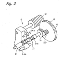
Fig. 3 is a perspective view of the oscillating mechanism; -
Fig. 4 is a partial longitudinal cross-sectional view of the oscillating mechanism; -
Fig. 5 is a cross-sectional view along the line V - V inFig. 4 ; -
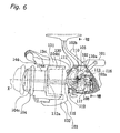
Fig. 6 is a cross-sectional view of a spinning reel in accordance with another embodiment of the present invention, taken from the left; -
Fig. 7 is a cross-sectional view along the line VII - VII inFig. 6 ; and -
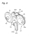
Fig. 8 is a perspective view of the oscillating mechanism in the other embodiment of the present invention. - As shown in
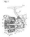
Fig. 1 , a spinning reel in accordance with an embodiment of the present invention includes areel unit 2, arotor 3, a spool 4, and a handle 1 that is rotatively supported by thereel unit 2. Therotor 3 is rotatively supported at the front of thereel unit 2. Fishing line is wound around the outer peripheral surface of the spool 4, which is disposed to permit shifting back and forth on the front of therotor 3. - As shown in
Figs. 1 and2 , thereel unit 2 includes areel body 2a provided with an opening 2c on its side, a T-shapedrod attachment leg 2b extending diagonally upward to the front from thereel body 2a and formed unitarily therewith, and alid 2d closing the opening 2c in thereel body 2a.
Thereel body 2a has a space inside, which accommodates arotor driving mechanism 5 and anoscillating mechanism 6. Therotor driving mechanism 5 transmits the rotation of the handle 1 to rotate therotor 3. The oscillatingmechanism 6 is for uniformly winding on fishing line by shifting the spool 4 back and forth. - At the front of the
reel body 2a, acircular flange portion 2e is formed with thelid 2d covering the rear of therotor 3. Atubular portion 2f protruding into therotor 3 is formed at the front of theflange portion 2e. Apartition wall 2g is formed inside thetubular portion 2f, and tubular spaces are formed on either side of thepartition wall 2g. - As shown in
Fig. 1 , therotor 3 includes abarrel portion 30 the rear end of which is open, and first andsecond rotor arms barrel portion 30. Thebarrel portion 30 and the tworotor arms - The
barrel portion 30 is disposed to the outer peripheral side of thetubular portion 2f of thereel body 2a. The open rear portion of thebarrel portion 30 is covered by theflange portion 2e. Afront wall 33 is formed on the front part of thebarrel portion 30, and aboss portion 33a is formed in the center of thefront wall 33. Afront portion 12a of thepinion gear 12 and thespool shaft 15 are passed through a through-hole in theboss portion 33a. Anut 34 is disposed at the front of thefront wall 33, and thisnut 34 fastens therotor 3 to thepinion gear 12 by screwing it to a threaded portion at the front end of thepinion gear 12. - A
bail arm 44 for guiding the fishing line to the spool 4is provided on the tips of the first andsecond rotor arms
A reverserotation check mechanism 50 for therotor 3 is provided in the space in front of thepartition wall 2g in thebarrel portion 30 of therotor 3. This reverserotation check mechanism 50 has a roller-type one-way clutch 51 and an operating mechanism for switching the one-way clutch 51 between an operating state and a non-operating state. The one-way clutch 51 has an outer ring fastened to thereel body 2a and an inner ring mounted non-rotatively to thepinion gear 12. Theoperating mechanism 52 includes an operatinglever 53 disposed on the rear of thereel body 2a. The one-way clutch 51 can be switched between its two positions by pivoting the operatinglever 53. When the one-way clutch 51 is in the operating state, therotor 3 cannot rotate in reverse, and when it is in the non-operating state, therotor 3 can rotate in reverse. - The spool 4 is arranged between the
first rotor arm 31 and thesecond rotor arm 32 of therotor 3, and is fastened to the front end of thespool shaft 15 with thedrag mechanism 60 interposed between thespool shaft 15 and the spool 4. The spool 4 includes a bobbin trunk portion 4a circumferentially around fishing line is wound, askirt portion 4b formed unitarily with the rear of the bobbin trunk portion 4a, and a flange portion 4c attached to the front of the bobbin trunk portion 4a. The bobbin trunk portion 4a is a cylindrical member extending to the outer peripheral side of thebarrel portion 30 of therotor 3. Theskirt portion 4b and the front flange portion 4c extend radially outward perpendicularly from both sides of the bobbin trunk portion 4a. Thus, the number of windings per layer of fishing line is approximately the same when the fishing line is being wound around the bobbin trunk portion 4a of the spool 4. - As shown in
Figs. 1 and2 , therotor driving mechanism 5 includes amain gear shaft 10, amain gear 11 and apinion gear 12. Themain gear 11 rotates together with themain gear shaft 10, on which the handle 1 is mounted non-rotatively. Thepinion gear 12 meshes with themain gear 11. Thepinion gear 12, which is tubular and rotates when the handle is turned, is pierced by the horizontally extendingspool shaft 15. The middle and the rear of thepinion gear 12 are supported rotatively withball bearings reel body 2a. Therotor 3 is mounted non-rotatively on the front end of thepinion gear 12. - The
oscillating mechanism 6 reciprocates thespool 3 back and forth via thespool shaft 15 when the handle 1 is turned. As shown inFigs. 2 to 5 , theoscillating mechanism 6 includes thepinion gear 12 serving as a drive gear, a steppedgear unit 13 meshing with thepinion gear 12, and ashifting mechanism 17 including a drivenhelical gear 16 meshing with the steppedgear unit 13. - The stepped
gear unit 13 is provided for gearing-down the rotation of thepinion gear 12 and transmitting it to the drivengear 16. The steppedgear unit 13 is placed in the space behind thepartition wall 2g of thetubular portion 2f. The steppedgear unit 13 is supported rotatively by thepartition wall 2g on a bearing 18 (seeFig. 4 ). The steppedgear unit 13 includes two gears of different size, namely a larger-diameter gear 19 meshing with thepinion gear 12, and a smaller-diameter gear 20 formed unitarily with thelarge diameter gear 19 and meshing with the drivengear 16. The smaller-diameter gear 20 is a helical gear arranged concentrically with the larger-diameter gear 19. - Employing the stepped
gear unit 13 having the twogears gear unit 13 is arranged in parallel to the rotational axes of thepinion gear 12 and the drivengear 16, so that it is easy to ensure a high manufacturing precision. Furthermore, the steppedgear unit 13 is arranged in thetubular portion 2f of thereel body 2a, so that it is not necessary to increase the lateral width of thereel body 2, even though deceleration is performed with the steppedgear unit 13 including the larger-diameter gear 19, which is relatively voluminous in the width direction (lateral direction). Thus, a compact reel can be accomplished. - The
pinion gear 12 has eight teeth, and the larger-diameter gear 19 has sixteen teeth, for example. The smaller-diameter gear 20 has five teeth, and the drivengear 16 has fifteen teeth, for example. Thus, the gear-down ratio, which is ratio between the rotation speed of thescrew axis 21 and the rotation speed of thepinion gear 12, is (1/2) X (5/15) = 1/6. It is preferable that this gear-down ratio is in the range of 1/4 to 1/24. If the gear-down ratio is less than 1/4, then the shifting speed of the spool 4 becomes too large, and the desired effect of winding the fishing line densely around the spool 4 cannot be attained. If the gear-down ratio is larger than 1/24, then the shifting speed of the spool 4 is too slow, and even thin lines are wound twice per rotation of therotor 3. It should be noted that the number of teeth inFigs. 3 to 5 may not correspond exactly to the above explanations. - 'The
shifting mechanism 17 includes a threadedshaft 21, aslider 22, and guideshafts shaft 21 is arranged below thespool shaft 15 and mounted to the front end of the drivengear 16. Theslider 22 moves back and forth along the threadedshaft 21, guided by the twoguide shafts
The threadedshaft 21 is arranged in parallel to thespool shaft 15, and is supported rotatively in thereel body 2a.Helical intersecting grooves 21a are formed in the outer peripheral portion of the threadedshaft 21. The lead angle θ of thegrooves 21a is set to 20 to 45°. Here, the "lead angle θ" is the angle
grooves 21a, and the lead L is the advance length in the axial direction per rotation of the threadedshaft 21. If this lead angle θ is smaller than 20°, the wall thickness between the grooves becomes thin, and the number of groove intersections increases, which is undesirable. On the other hand, if the lead angle θ is greater than 45°, the efficiency with which the rotational movement is converted into a linear movement decreases, which is also undesirable. - The
slider 22 includes amain slider unit 25 and an engaging member 26 accommodated in themain slider unit 25. Themain slider unit 25 is guided in parallel to thespool shaft 15 by theguide shafts main slider unit 25, and the front end of the engaging member 26 meshes with thegrooves 21a in the threadedshaft 21. - When casting with this spinning reel, the
bail arm 44 falls from the line-winding position to the line-releasing position. Then, the tackle is cast by swinging the rod. Thus, fishing line is released in a helical fashion from the front end of the spool 4. In this situation, the fishing line is wound densely around the spool 4, so that there is low releasing resistance. - When winding on fishing line, the
bail arm 44 is tripped into line-winding position. This happens automatically due to the action of a cam and a spring (not shown in the drawings) when the handle 1 is turned in the line-winding direction. When the handle 1 is turned in the line-winding direction, its torque is transmitted via themain gear shaft 10 and themain gear 11 to thepinion gear 12. The torque transmitted to thepinion gear 12 is transmitted over thefront portion 12a of thepinion gear 12 to therotor 3, rotating therotor 3 in the line-winding direction. - In addition, the stepped
gear portion 13 is rotated by the larger-diameter gear 19 meshing with thepinion gear 12, and this rotation is transmitted to the drivengear 16 via the small-rotation gear 20. As a result, the threadedshaft 21 is rotated at 1/6 of the rotation speed of the pinion gear 12 (rotation speed of the rotor 3). The rotation of the threadedshaft 21 causes theslider 22 meshing with thegrooves 21a of the threadedshaft 21 to shift in the front-to-rear direction, guided by theguide shafts bail arm 44 and wound densely around the bobbin trunk portion 4a of the spool 4. Thus, the fishing line can be wound with high efficiency onto the spool 4. - (a) The previous embodiment has been explained with an example of a traverse cam oscillating mechanism. However, as shown in
Figs. 6 to 8 the present invention can also be applied to a reduction gear oscillating mechanism. Here, elements that are identical and similar to those in the previous embodiment are denoted by like numerals plus 100. Also, except for theoscillating mechanism 106, explanations regarding structure and operation have been omitted. - As shown in
Figs. 6 to 8 , theoscillating mechanism 106 includes adrive gear 110a formed on amain gear shaft 110 that is formed unitarily with themain gear 111, a steppedgear unit 13 meshing with the drivengear 110a, and ashifting mechanism 117 including a drivengear 116 meshing with the smaller-diameter gear 120 of the steppedgear unit 113.
The steppedgear unit 113 and the drivengear 116 are supported rotatively in the inner side of the rear wall of thereel body 102a. The steppedgear unit 113 and the drivengear 116 are arranged parallel to themain gear shaft 110. In this embodiment, the larger-diameter gear 119 of the steppedgear unit 113 meshes with thedrive gear 110a, and the smaller-diameter gear 120 meshes with the drivengear 116. - The
shifting mechanism 117 includes a drivengear 116 and aslider 112 disposed in opposition to the drivengear 116. Acam pin 116a is formed on the lateral face of the drivengear 116, protruding toward theslider 122.
Theslider 122 can be shifted back and forth in thereel body 102a. Theslider 122 is fitted non-rotatively on the rear end of thespool shaft 115, and is not shiftable with respect to thespool shaft 115 in the axial direction. Avertical cam groove 122a is formed in the lateral face of theslider 122, in opposition to the drivengear 116. Thecam pin 116a engages with thiscam groove 122a. The length of thecam groove 122a is a little greater than the rotational diameter of thecam pin 116a. - Rotating the
main gear shaft 110 in a reduction gearoscillating mechanism 106 with this configuration, the drivengear 116 is rotated via the steppedgear unit 113, and thecam pin 116a is rotated. When thecam pin 116a rotates, theslider 122 shifts back and forth since thecam pin 116a is engaged with thecam groove 122a, thus moving thespool 104 back and forth. Thus, with the steppedgear unit 113, it is possible to attain a large gear-down ratio with a simple configuration, and to keep the manufacturing costs down, due to this simple configuration for dense winding. - (b) The above embodiments have been described taking an example of a front drag spinning reel, but the present invention can also be applied to oscillating mechanisms in rear drag spinning reels, for example. In that case, the spool shaft is coupled rotatively and axially immovably to the slider. Moreover, the present invention can also be applied to lever brake type spinning reels and in-spool type spinning reels.
- (c) In the above embodiments, the threaded
shaft 21 is arranged below thespool shaft 15, but it can also be arranged sideways (laterally) or above it.
(d) In the above embodiments, the rotational axes of the smaller-diameter gear 20 of the steppedgear unit 13 and of thereduction gear 16 are configured as parallel helical gears, but they can also be configured so as to transmit a rotational movement between two intersecting or skew rotational axes. For example, the two gears can also be configured as bevel gears or crossed helical gears with a relatively simple structure. - Through the present invention, rotational gearing-down is accomplished with a stepped gear unit of simple structure to reciprocate the spool, making it unnecessary to use special gears, and holding down elevation in manufacturing costs. The rotational axis of the stepped gear unit is arranged in parallel to the rotational axes of the drive gear and the driven gear, so that it is easy to ensure a high manufacturing precision.
While only selected embodiments have been chosen to illustrate the present invention, to those skilled in the art it will be apparent from this disclosure that various changes and modifications can be made herein without departing from the scope of the invention as defined in the appended claims. Furthermore, the foregoing description of the embodiments according to the present invention is provided for illustration only, and not for the purpose of limiting the invention as defined by the appended claims and their equivalents.
Claims (9)
- A spinning reel reciprocating device (106) for reciprocating a spool (104) back and forth in cooperation with rotation of a handle (101) furnished on a spinning-reel unit (102) to which a fishing-line-guiding rotor (103) is rotatively fitted, the rotation of the handle (101) being transmitted to the rotor (103) via a pinion gear (112), the spinning reel reciprocating device (106) comprising:a main gear (111) for rotating together with the rotation of the handle (101);a drive gear (110a) for rotating in cooperation with rotation of the handle (101);a stepped gear unit (113) including a larger-diameter gear (119) having more teeth than the drive gear (110a) and meshing with the drive gear (110a), and a smaller-diameter gear (120) disposed concentric with the larger-diameter gear (119) and rotating unitarily with the larger-diameter gear (119); andshifting means (117) having a driven gear (116) meshing with the smaller-diameter gear (120) and a slider (122) that is disposed facing the driven gear (116) and axially immovably coupled to a spool shaft (115) onto which the spool (104) is attached, the shifting means (117) being for reciprocating the spool (104) by rotation of the driven gear (116), the driven gear (116) having more teeth than the smaller-diameter gear (120),characterised in that the drive gear (110a) is disposed on an opposite side of the pinion gear (112) than the main gear (111).
- The spinning reel reciprocating device (106) as set forth in claim 1, wherein:the rotor (103) has a barrel portion (130) and a pair of rotor arms (131,132) extending frontward from the barrel portion (130) rear-endwise, and the reel unit (102) has a tubular portion extending interiorly into the barrel portion (130); andthe stepped gear unit (113) is disposed interiorly in the tubular portion.
- The spinning reel reciprocating device (106) as set forth in claim 1 or claim 2, wherein:said driven gear (116) includes a cam pin (116a) protruding from a lateral face of said driven gear (116); andsaid slider,(122) is fitted reciprocatingly to the reel unit (102) and has a cam groove (122a) on a lateral face of said slider (122) that opposes said driven gear (116) such that said cam pin (116a) engages said cam groove (122a), said cam groove (122a) extending in a direction that intersects with a direction in which the spool (104) moves.
- The spinning reel reciprocating device (106) as set forth in claim 3, wherein
a length of said cam groove (122a) is greater than a diameter of a circle along which said cam pin (116a) pivots. - The spinning reel reciprocating device (106) as set forth in any of claims 1 to 4, wherein:said stepped gear unit (113) and said driven gear (116) are both supported by the reel unit (102).
- The spinning reel reciprocating device (106) as set forth in any preceding claim, wherein
said smaller-diameter gear (120) is disposed closer to said slider (122) relative to said larger-diameter gear (119). - The spinning reel reciprocating device (106) as set forth in any preceding claim, wherein:said drive gear (110a) is provided on a main gear shaft (110) that is mounted rotatively in the reel unit (102) so as to rotate unitarily with the handle (101); andthe spool shaft (115), which is axially movably mounted in the reel unit (102) and forward-endwise onto which the spool (104) is attached, is fitted axially immovable to said slider (122).
- A spinning reel, comprising:a reel unit (102) having a reciprocating mechanism (106), as claimed in any preceding claim;a rotor (103) rotatively supported at a front portion of said reel unit (102);a handle (101) rotatively supported by said reel unit (102), the rotation of said handle (101) being transmitted to said rotor (103) via a pinion gear (112); anda spool (104) disposed on a front portion of said rotor (103) so as to be shiftable in a front-back direction through said reciprocating mechanism (106).
- The spinning reel as set forth in claim 8, wherein:said reel unit (102) has a reel body (102a) having an opening on its side, and a lid member for closing said opening, and a handle shaft (110) about which said handle (101) rotates is supported by both said reel body (102) and said lid member.
Applications Claiming Priority (3)
| Application Number | Priority Date | Filing Date | Title |
|---|---|---|---|
| JP2000145964A JP2001321041A (en) | 2000-05-18 | 2000-05-18 | Reciprocating moving device for spinning reel |
| JP2000145964 | 2000-05-18 | ||
| EP01304292A EP1155613B1 (en) | 2000-05-18 | 2001-05-14 | Spinning-Reel reciprocating device |
Related Parent Applications (1)
| Application Number | Title | Priority Date | Filing Date |
|---|---|---|---|
| EP01304292A Division EP1155613B1 (en) | 2000-05-18 | 2001-05-14 | Spinning-Reel reciprocating device |
Publications (3)
| Publication Number | Publication Date |
|---|---|
| EP1525794A2 EP1525794A2 (en) | 2005-04-27 |
| EP1525794A3 EP1525794A3 (en) | 2005-05-11 |
| EP1525794B1 true EP1525794B1 (en) | 2008-03-26 |
Family
ID=18652398
Family Applications (2)
| Application Number | Title | Priority Date | Filing Date |
|---|---|---|---|
| EP01304292A Expired - Lifetime EP1155613B1 (en) | 2000-05-18 | 2001-05-14 | Spinning-Reel reciprocating device |
| EP05000794A Expired - Lifetime EP1525794B1 (en) | 2000-05-18 | 2001-05-14 | Spinning-reel reciprocating device |
Family Applications Before (1)
| Application Number | Title | Priority Date | Filing Date |
|---|---|---|---|
| EP01304292A Expired - Lifetime EP1155613B1 (en) | 2000-05-18 | 2001-05-14 | Spinning-Reel reciprocating device |
Country Status (10)
| Country | Link |
|---|---|
| US (2) | US6412721B2 (en) |
| EP (2) | EP1155613B1 (en) |
| JP (1) | JP2001321041A (en) |
| KR (1) | KR100722535B1 (en) |
| CN (2) | CN1193660C (en) |
| AT (2) | ATE390048T1 (en) |
| DE (2) | DE60133427T2 (en) |
| MY (1) | MY124891A (en) |
| SG (1) | SG98445A1 (en) |
| TW (1) | TW588581U (en) |
Families Citing this family (28)
| Publication number | Priority date | Publication date | Assignee | Title |
|---|---|---|---|---|
| JP2002101792A (en) * | 2000-09-18 | 2002-04-09 | Shimano Singapore Pte Ltd | Spinning-reel oscillating mechanism |
| US6682007B2 (en) * | 2001-03-15 | 2004-01-27 | Kabushiki Kaisha Johshuya | Spinning reel having improved spool oscillating mechanism |
| JP2003079291A (en) * | 2001-09-12 | 2003-03-18 | Shimano Inc | Reciprocally shifting mechanism of spinning reel |
| JP2003225040A (en) * | 2002-02-04 | 2003-08-12 | Shimano Inc | Power transmission unit for fishing reel |
| JP3926198B2 (en) * | 2002-04-19 | 2007-06-06 | 株式会社シマノ | Spinning reel screw shaft mounting structure |
| US6626385B1 (en) * | 2002-08-01 | 2003-09-30 | Daiwa Seiko, Inc. | Spinning reel for fishing |
| JP2004081077A (en) * | 2002-08-26 | 2004-03-18 | Shimano Inc | Reciprocation mechanism for spinning reel |
| US7118059B2 (en) | 2003-01-29 | 2006-10-10 | Shimano Inc. | Reel unit for spinning reel |
| TWI315185B (en) | 2003-05-15 | 2009-10-01 | Shimano Kk | Drag adjustment knob for a spinning reel |
| JP4299180B2 (en) * | 2003-08-27 | 2009-07-22 | 株式会社シマノ | Spinning reel reciprocating device |
| US7413175B2 (en) | 2005-03-31 | 2008-08-19 | Xerox Corporation | Automated cover-driven workflows for manufacturing books in a production environment |
| GB0608383D0 (en) * | 2006-04-27 | 2006-06-07 | Fox Int Group Ltd | A fixed spool fishing reel |
| US7802744B2 (en) * | 2007-09-14 | 2010-09-28 | Shimano Inc. | Spinning reel |
| US8176737B2 (en) * | 2008-07-31 | 2012-05-15 | Caterpillar Inc. | Exhaust system having 3-way valve |
| JP5143757B2 (en) * | 2009-01-26 | 2013-02-13 | 株式会社シマノ | Fishing reel screw shaft and fishing reel reciprocating mechanism using the same |
| US9254145B2 (en) * | 2010-03-11 | 2016-02-09 | Advanced Catheter Therapies, Inc. | Atherectomy device |
| JP6140956B2 (en) * | 2012-09-18 | 2017-06-07 | 株式会社シマノ | Spinning reel |
| CN103004713B (en) * | 2012-11-30 | 2014-05-07 | 宁波海宝渔具有限公司 | Gear-driven gapless fishing line reel for fishing |
| KR102312398B1 (en) * | 2013-10-01 | 2021-10-13 | 가부시키가이샤 시마노 | Oscillation mechanism for fishing reel |
| CN103875621B (en) * | 2013-10-21 | 2017-06-16 | 东莞市凯特渔具制造有限公司 | Spinning-reel cam drive |
| JP6656813B2 (en) * | 2015-03-10 | 2020-03-04 | 株式会社シマノ | Fishing reel reciprocating mechanism and fishing reel |
| CN112674049A (en) * | 2015-12-18 | 2021-04-20 | 古洛布莱株式会社 | Spinning reel for fishing |
| CN107873662A (en) * | 2016-09-30 | 2018-04-06 | 宁波海宝渔具有限公司 | The two-axis winder of the fishing of variable-ratio |
| CN108990931A (en) * | 2017-06-07 | 2018-12-14 | 纯钓日本公司 | Spinning wheel type fishing reel is used in fishing |
| JP6908447B2 (en) * | 2017-06-27 | 2021-07-28 | 株式会社シマノ | Reciprocating mechanism of fishing reel |
| JP7046743B2 (en) * | 2018-07-06 | 2022-04-04 | 株式会社シマノ | Spinning reel |
| TWI737994B (en) * | 2019-05-14 | 2021-09-01 | 宏正自動科技股份有限公司 | A speed reduction device and wire winding device using the same |
| JP7385525B2 (en) * | 2020-05-18 | 2023-11-22 | 株式会社シマノ | spinning reel |
Family Cites Families (16)
| Publication number | Priority date | Publication date | Assignee | Title |
|---|---|---|---|---|
| US583913A (en) * | 1897-06-08 | Fishing-reel | ||
| US982305A (en) * | 1908-07-13 | 1911-01-24 | William Shakespeare Jr Company | Fishing-reel. |
| CH258217A (en) * | 1945-10-05 | 1948-11-30 | Huillet Jean | Reel for casting fishing. |
| GB645978A (en) | 1948-08-03 | 1950-11-15 | Carpano & Pons | An improved reel for fly fishing |
| US2686016A (en) * | 1949-10-20 | 1954-08-10 | Rudolph R Kilian | Fishing reel |
| US2726052A (en) * | 1952-12-19 | 1955-12-06 | Carpano & Pons | Fishing reel |
| US3055607A (en) | 1961-05-19 | 1962-09-25 | Angelgerate Manufaktur D A M H | Fishing reel with spool transversing mechanism |
| US4026493A (en) * | 1976-07-16 | 1977-05-31 | Anderson William C | Hydraulic drive for fishing reel having variable takeup ratio |
| JPH0774327B2 (en) | 1987-02-14 | 1995-08-09 | 日東電工株式会社 | UV curable silicone release agent |
| US5316239A (en) * | 1990-07-10 | 1994-05-31 | Shimano Inc. | Spinning reel with oscillating mechanism |
| US5232181A (en) * | 1991-05-24 | 1993-08-03 | Olympic Co., Ltd. | Spinning reel for fishing |
| JPH0521663U (en) * | 1991-09-09 | 1993-03-23 | 株式会社シマノ | Oscillating mechanism of spinning reel |
| JP3199351B2 (en) * | 1995-07-04 | 2001-08-20 | ダイワ精工株式会社 | Spinning reel |
| JP3292366B2 (en) * | 1996-09-09 | 2002-06-17 | ダイワ精工株式会社 | Spinning reel for fishing |
| US5878523A (en) * | 1997-10-30 | 1999-03-09 | Wenzel; Stephen R. | Motorized reeling assembly with automatic cut-off |
| US6264125B1 (en) * | 1999-12-09 | 2001-07-24 | Brunswick Corporation | Asymmetric oscillation mechanism for a spinning reel |
-
2000
- 2000-05-18 JP JP2000145964A patent/JP2001321041A/en active Pending
-
2001
- 2001-04-16 TW TW091212769U patent/TW588581U/en not_active IP Right Cessation
- 2001-05-09 KR KR1020010025263A patent/KR100722535B1/en not_active IP Right Cessation
- 2001-05-14 AT AT05000794T patent/ATE390048T1/en not_active IP Right Cessation
- 2001-05-14 SG SG200102871A patent/SG98445A1/en unknown
- 2001-05-14 DE DE60133427T patent/DE60133427T2/en not_active Expired - Lifetime
- 2001-05-14 US US09/853,776 patent/US6412721B2/en not_active Expired - Fee Related
- 2001-05-14 AT AT01304292T patent/ATE320708T1/en not_active IP Right Cessation
- 2001-05-14 EP EP01304292A patent/EP1155613B1/en not_active Expired - Lifetime
- 2001-05-14 EP EP05000794A patent/EP1525794B1/en not_active Expired - Lifetime
- 2001-05-14 DE DE60118116T patent/DE60118116T2/en not_active Expired - Lifetime
- 2001-05-16 MY MYPI20012314 patent/MY124891A/en unknown
- 2001-05-18 CN CNB011196149A patent/CN1193660C/en not_active Expired - Fee Related
- 2001-05-18 CN CNB2005100044852A patent/CN100377643C/en not_active Expired - Fee Related
-
2002
- 2002-05-20 US US10/147,850 patent/US6484956B2/en not_active Expired - Fee Related
Also Published As
| Publication number | Publication date |
|---|---|
| CN1631129A (en) | 2005-06-29 |
| KR100722535B1 (en) | 2007-05-28 |
| DE60133427D1 (en) | 2008-05-08 |
| US6412721B2 (en) | 2002-07-02 |
| CN1193660C (en) | 2005-03-23 |
| CN100377643C (en) | 2008-04-02 |
| CN1324565A (en) | 2001-12-05 |
| MY124891A (en) | 2006-07-31 |
| EP1155613B1 (en) | 2006-03-22 |
| US20010042804A1 (en) | 2001-11-22 |
| EP1155613A1 (en) | 2001-11-21 |
| US6484956B2 (en) | 2002-11-26 |
| EP1525794A2 (en) | 2005-04-27 |
| DE60118116D1 (en) | 2006-05-11 |
| EP1525794A3 (en) | 2005-05-11 |
| KR20010105169A (en) | 2001-11-28 |
| ATE390048T1 (en) | 2008-04-15 |
| SG98445A1 (en) | 2003-09-19 |
| JP2001321041A (en) | 2001-11-20 |
| TW588581U (en) | 2004-05-21 |
| US20020134873A1 (en) | 2002-09-26 |
| DE60118116T2 (en) | 2006-10-26 |
| DE60133427T2 (en) | 2009-04-23 |
| ATE320708T1 (en) | 2006-04-15 |
Similar Documents
| Publication | Publication Date | Title |
|---|---|---|
| EP1525794B1 (en) | Spinning-reel reciprocating device | |
| EP1169919B1 (en) | Spinning-Reel Reciprocating Device | |
| EP1810566A1 (en) | Gear mounting structure for fishing reel | |
| EP2454938A1 (en) | Fishing reel gear attachment structure | |
| EP1332670B1 (en) | Fishing-reel power transmission device | |
| EP0054425B1 (en) | Fishing reel | |
| EP1082899B1 (en) | Spinning reel rotation transmission device | |
| EP1541019A2 (en) | Spinning reel oscillating device | |
| JP2003225040A5 (en) | ||
| US5388777A (en) | Spinning reel with improved control structure of stopper mechanism | |
| JPH09140302A (en) | Fishing reel of double-bearing type | |
| JP2005253477A (en) | Reciprocally moving device of spinning reel | |
| JP4047534B2 (en) | Fishing spinning reel | |
| US6224006B1 (en) | Spinning reel having tapered spool and compact reel body | |
| JP2002125538A (en) | Device for reciprocating spinning reel | |
| JP4023802B2 (en) | Fishing reel | |
| JP3086776B2 (en) | Electric fishing reel | |
| KR920008580Y1 (en) | Spool of spinning reel in the fishing | |
| JPH07255335A (en) | Spool reciprocation device of backward drag type spinning reel for fishing | |
| JPH0582280U (en) | Spinning reel |
Legal Events
| Date | Code | Title | Description |
|---|---|---|---|
| PUAI | Public reference made under article 153(3) epc to a published international application that has entered the european phase |
Free format text: ORIGINAL CODE: 0009012 |
|
| PUAL | Search report despatched |
Free format text: ORIGINAL CODE: 0009013 |
|
| AC | Divisional application: reference to earlier application |
Ref document number: 1155613 Country of ref document: EP Kind code of ref document: P |
|
| AK | Designated contracting states |
Kind code of ref document: A2 Designated state(s): AT BE CH CY DE DK ES FI FR GB GR IE IT LI LU MC NL PT SE TR |
|
| AK | Designated contracting states |
Kind code of ref document: A3 Designated state(s): AT BE CH CY DE DK ES FI FR GB GR IE IT LI LU MC NL PT SE TR |
|
| RIN1 | Information on inventor provided before grant (corrected) |
Inventor name: SUGAWARA, KENICHIC/O SHIMANO INC Inventor name: KAWABE, YUZO |
|
| 17P | Request for examination filed |
Effective date: 20050607 |
|
| AKX | Designation fees paid |
Designated state(s): AT BE CH CY DE DK ES FI FR GB GR IE IT LI LU MC NL PT SE TR |
|
| RAP1 | Party data changed (applicant data changed or rights of an application transferred) |
Owner name: SHIMANO INC. |
|
| GRAP | Despatch of communication of intention to grant a patent |
Free format text: ORIGINAL CODE: EPIDOSNIGR1 |
|
| GRAS | Grant fee paid |
Free format text: ORIGINAL CODE: EPIDOSNIGR3 |
|
| GRAA | (expected) grant |
Free format text: ORIGINAL CODE: 0009210 |
|
| AC | Divisional application: reference to earlier application |
Ref document number: 1155613 Country of ref document: EP Kind code of ref document: P |
|
| AK | Designated contracting states |
Kind code of ref document: B1 Designated state(s): AT BE CH CY DE DK ES FI FR GB GR IE IT LI LU MC NL PT SE TR |
|
| REG | Reference to a national code |
Ref country code: GB Ref legal event code: FG4D |
|
| REG | Reference to a national code |
Ref country code: CH Ref legal event code: EP Ref country code: IE Ref legal event code: FG4D |
|
| REF | Corresponds to: |
Ref document number: 60133427 Country of ref document: DE Date of ref document: 20080508 Kind code of ref document: P |
|
| PG25 | Lapsed in a contracting state [announced via postgrant information from national office to epo] |
Ref country code: FI Free format text: LAPSE BECAUSE OF FAILURE TO SUBMIT A TRANSLATION OF THE DESCRIPTION OR TO PAY THE FEE WITHIN THE PRESCRIBED TIME-LIMIT Effective date: 20080326 |
|
| PG25 | Lapsed in a contracting state [announced via postgrant information from national office to epo] |
Ref country code: AT Free format text: LAPSE BECAUSE OF FAILURE TO SUBMIT A TRANSLATION OF THE DESCRIPTION OR TO PAY THE FEE WITHIN THE PRESCRIBED TIME-LIMIT Effective date: 20080326 |
|
| NLV1 | Nl: lapsed or annulled due to failure to fulfill the requirements of art. 29p and 29m of the patents act | ||
| PG25 | Lapsed in a contracting state [announced via postgrant information from national office to epo] |
Ref country code: BE Free format text: LAPSE BECAUSE OF FAILURE TO SUBMIT A TRANSLATION OF THE DESCRIPTION OR TO PAY THE FEE WITHIN THE PRESCRIBED TIME-LIMIT Effective date: 20080326 |
|
| PG25 | Lapsed in a contracting state [announced via postgrant information from national office to epo] |
Ref country code: PT Free format text: LAPSE BECAUSE OF FAILURE TO SUBMIT A TRANSLATION OF THE DESCRIPTION OR TO PAY THE FEE WITHIN THE PRESCRIBED TIME-LIMIT Effective date: 20080901 Ref country code: ES Free format text: LAPSE BECAUSE OF FAILURE TO SUBMIT A TRANSLATION OF THE DESCRIPTION OR TO PAY THE FEE WITHIN THE PRESCRIBED TIME-LIMIT Effective date: 20080707 Ref country code: SE Free format text: LAPSE BECAUSE OF FAILURE TO SUBMIT A TRANSLATION OF THE DESCRIPTION OR TO PAY THE FEE WITHIN THE PRESCRIBED TIME-LIMIT Effective date: 20080626 |
|
| PG25 | Lapsed in a contracting state [announced via postgrant information from national office to epo] |
Ref country code: NL Free format text: LAPSE BECAUSE OF FAILURE TO SUBMIT A TRANSLATION OF THE DESCRIPTION OR TO PAY THE FEE WITHIN THE PRESCRIBED TIME-LIMIT Effective date: 20080326 |
|
| ET | Fr: translation filed | ||
| PG25 | Lapsed in a contracting state [announced via postgrant information from national office to epo] |
Ref country code: MC Free format text: LAPSE BECAUSE OF NON-PAYMENT OF DUE FEES Effective date: 20080531 |
|
| REG | Reference to a national code |
Ref country code: CH Ref legal event code: PL |
|
| PG25 | Lapsed in a contracting state [announced via postgrant information from national office to epo] |
Ref country code: DK Free format text: LAPSE BECAUSE OF FAILURE TO SUBMIT A TRANSLATION OF THE DESCRIPTION OR TO PAY THE FEE WITHIN THE PRESCRIBED TIME-LIMIT Effective date: 20080326 Ref country code: LI Free format text: LAPSE BECAUSE OF NON-PAYMENT OF DUE FEES Effective date: 20080531 Ref country code: CH Free format text: LAPSE BECAUSE OF NON-PAYMENT OF DUE FEES Effective date: 20080531 |
|
| PLBE | No opposition filed within time limit |
Free format text: ORIGINAL CODE: 0009261 |
|
| STAA | Information on the status of an ep patent application or granted ep patent |
Free format text: STATUS: NO OPPOSITION FILED WITHIN TIME LIMIT |
|
| 26N | No opposition filed |
Effective date: 20081230 |
|
| PG25 | Lapsed in a contracting state [announced via postgrant information from national office to epo] |
Ref country code: IE Free format text: LAPSE BECAUSE OF NON-PAYMENT OF DUE FEES Effective date: 20080514 |
|
| PG25 | Lapsed in a contracting state [announced via postgrant information from national office to epo] |
Ref country code: IT Free format text: LAPSE BECAUSE OF FAILURE TO SUBMIT A TRANSLATION OF THE DESCRIPTION OR TO PAY THE FEE WITHIN THE PRESCRIBED TIME-LIMIT Effective date: 20080326 |
|
| PG25 | Lapsed in a contracting state [announced via postgrant information from national office to epo] |
Ref country code: CY Free format text: LAPSE BECAUSE OF FAILURE TO SUBMIT A TRANSLATION OF THE DESCRIPTION OR TO PAY THE FEE WITHIN THE PRESCRIBED TIME-LIMIT Effective date: 20080326 |
|
| PG25 | Lapsed in a contracting state [announced via postgrant information from national office to epo] |
Ref country code: LU Free format text: LAPSE BECAUSE OF NON-PAYMENT OF DUE FEES Effective date: 20080514 |
|
| PG25 | Lapsed in a contracting state [announced via postgrant information from national office to epo] |
Ref country code: TR Free format text: LAPSE BECAUSE OF FAILURE TO SUBMIT A TRANSLATION OF THE DESCRIPTION OR TO PAY THE FEE WITHIN THE PRESCRIBED TIME-LIMIT Effective date: 20080326 |
|
| PG25 | Lapsed in a contracting state [announced via postgrant information from national office to epo] |
Ref country code: GR Free format text: LAPSE BECAUSE OF FAILURE TO SUBMIT A TRANSLATION OF THE DESCRIPTION OR TO PAY THE FEE WITHIN THE PRESCRIBED TIME-LIMIT Effective date: 20080627 |
|
| PGFP | Annual fee paid to national office [announced via postgrant information from national office to epo] |
Ref country code: DE Payment date: 20130515 Year of fee payment: 13 Ref country code: GB Payment date: 20130508 Year of fee payment: 13 |
|
| PGFP | Annual fee paid to national office [announced via postgrant information from national office to epo] |
Ref country code: FR Payment date: 20130531 Year of fee payment: 13 |
|
| REG | Reference to a national code |
Ref country code: DE Ref legal event code: R119 Ref document number: 60133427 Country of ref document: DE |
|
| GBPC | Gb: european patent ceased through non-payment of renewal fee |
Effective date: 20140514 |
|
| REG | Reference to a national code |
Ref country code: DE Ref legal event code: R119 Ref document number: 60133427 Country of ref document: DE Effective date: 20141202 |
|
| REG | Reference to a national code |
Ref country code: FR Ref legal event code: ST Effective date: 20150130 |
|
| PG25 | Lapsed in a contracting state [announced via postgrant information from national office to epo] |
Ref country code: DE Free format text: LAPSE BECAUSE OF NON-PAYMENT OF DUE FEES Effective date: 20141202 |
|
| PG25 | Lapsed in a contracting state [announced via postgrant information from national office to epo] |
Ref country code: FR Free format text: LAPSE BECAUSE OF NON-PAYMENT OF DUE FEES Effective date: 20140602 Ref country code: GB Free format text: LAPSE BECAUSE OF NON-PAYMENT OF DUE FEES Effective date: 20140514 |