EP1524043B1 - Procédé de forgeage d'un élément d'engrenage comprenant un bossage, et élément d'engrenage comprenant un bossage - Google Patents
Procédé de forgeage d'un élément d'engrenage comprenant un bossage, et élément d'engrenage comprenant un bossage Download PDFInfo
- Publication number
- EP1524043B1 EP1524043B1 EP04024090A EP04024090A EP1524043B1 EP 1524043 B1 EP1524043 B1 EP 1524043B1 EP 04024090 A EP04024090 A EP 04024090A EP 04024090 A EP04024090 A EP 04024090A EP 1524043 B1 EP1524043 B1 EP 1524043B1
- Authority
- EP
- European Patent Office
- Prior art keywords
- boss
- molding
- geared member
- molded
- raw material
- Prior art date
- Legal status (The legal status is an assumption and is not a legal conclusion. Google has not performed a legal analysis and makes no representation as to the accuracy of the status listed.)
- Expired - Lifetime
Links
- 238000000034 method Methods 0.000 title claims abstract description 47
- 238000000465 moulding Methods 0.000 title claims abstract description 41
- 239000002994 raw material Substances 0.000 claims abstract description 22
- 238000001125 extrusion Methods 0.000 claims abstract description 9
- 238000004513 sizing Methods 0.000 claims description 3
- 230000006835 compression Effects 0.000 claims description 2
- 238000007906 compression Methods 0.000 claims description 2
- 238000000748 compression moulding Methods 0.000 claims 1
- 230000008878 coupling Effects 0.000 description 16
- 238000010168 coupling process Methods 0.000 description 16
- 238000005859 coupling reaction Methods 0.000 description 16
- 238000010273 cold forging Methods 0.000 description 9
- 238000004519 manufacturing process Methods 0.000 description 8
- 239000000463 material Substances 0.000 description 3
- 238000005520 cutting process Methods 0.000 description 2
- 238000010297 mechanical methods and process Methods 0.000 description 2
- 230000005226 mechanical processes and functions Effects 0.000 description 2
- 238000005498 polishing Methods 0.000 description 2
- 230000005540 biological transmission Effects 0.000 description 1
- 238000006243 chemical reaction Methods 0.000 description 1
- 230000003247 decreasing effect Effects 0.000 description 1
- 230000001419 dependent effect Effects 0.000 description 1
- 238000005242 forging Methods 0.000 description 1
- 239000002184 metal Substances 0.000 description 1
- 239000007769 metal material Substances 0.000 description 1
- 230000001590 oxidative effect Effects 0.000 description 1
- 239000000843 powder Substances 0.000 description 1
- 230000001105 regulatory effect Effects 0.000 description 1
- 238000005245 sintering Methods 0.000 description 1
Images

Classifications
-
- B—PERFORMING OPERATIONS; TRANSPORTING
- B21—MECHANICAL METAL-WORKING WITHOUT ESSENTIALLY REMOVING MATERIAL; PUNCHING METAL
- B21K—MAKING FORGED OR PRESSED METAL PRODUCTS, e.g. HORSE-SHOES, RIVETS, BOLTS OR WHEELS
- B21K1/00—Making machine elements
- B21K1/28—Making machine elements wheels; discs
- B21K1/30—Making machine elements wheels; discs with gear-teeth
Definitions
- the present invention relates to a method for molding a geared member with a boss that is applicable to various kinds of couplings (e.g., a rigid coupling, a flexible joint, a universal joint and an Oldham's coupling for coupling the drive shaft and the driven shaft.
- various kinds of couplings e.g., a rigid coupling, a flexible joint, a universal joint and an Oldham's coupling for coupling the drive shaft and the driven shaft.
- a method for molding a geared member with a boss according to the preamble of claim 1 is known from United States Patent Laid-open Publication Number US 4,939,829 .
- geared member with boss various types are applied conventionally to a transmission for automobile, for example.
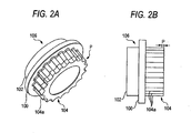
- Figs. 2A and 2B show a geared member with a boss 106 in which a boss portion 102 is molded at one end of a flange 100 and a gearing portion 104 is molded at the other end.
- a plurality of convex teeth 104a are molded at a predetermined pitch along the circumferential direction.
- the molding methods are well known as disclosed in the following patent documents, for example.
- a plurality of teeth 104a are molded by sintering and forging. More specifically, metal powder is compression molded within a mold while being sintered in the atmosphere of non-oxidizing gas, and sized into a predetermined toothed shape by cold forging.
- a step portion is provided on a mandrel for use in cold forging, and a partial molding pressure at the time of cold forging is directly applied from the step portion to the rawmaterial, so that the rawmaterial is sized into an intended toothed shape.
- a tooth end portion P (an extended end portion P of the plurality of teeth 104a extending from a flange 100 to the other side) of the gearing portion 104 may be chamfered.
- a chamfer is provided on the tooth end portion P of the gearing portion 104 by the conventional molding method, an excessive pressure must be exerted within a mold to produce the chamfer shape, in which there was a fear that the mold might be damaged by the molding pressure.
- a mechanical process e.g., cutting, polishing, etc.
- This invention has been achieved to solve the above-mentioned problems, and it is an object of the invention to provide a molding method for molding a geared member with a boss at a high manufacturing efficiency and a low price by providing the chamfer on the gear end portion of the gearing portion in a series of operation processes without providing an additional operation process for chamfering.
- the invention provides a method for molding a geared member with a boss according to claim 1.
- a method for molding a geared member with a boss according to one embodiment of the present invention will be described below.
- the geared member with a boss 2 molded by a method according to this embodiment comprises a boss portion 6 molded at one end of a flange 4, and a gearing portion 8 molded continuously from a toothed chamfer portion P at the other end.
- the gearing portion 8 has a plurality of teeth 8a molded continuously from the toothed chamfer portion P to one end.
- the toothed chamfer portion P is molded at a tooth end portion of the plurality of teeth 8a extending from the flange 4 to the other end.
- the geared member with boss 2 is applicable to various kinds of couplings (e.g., a rigid coupling, a flexible joint, a universal joint and an Oldham's coupling for coupling the drive shaft and the driven shaft), for which the plurality of teeth 8a are molded continuously at a predetermined pitch along the circumferential direction around the outer circumference of the gearing portion 8.
- couplings e.g., a rigid coupling, a flexible joint, a universal joint and an Oldham's coupling for coupling the drive shaft and the driven shaft
- the gearing portion 8 is sized into any geometry and the toothed chamfer portion P set to any curvature in accordance with the kind and geometry of the coupling to apply the geared member with boss 2.
- a hollow cylindrical metallic raw material 10 is prepared as the raw material for the geared member with boss 2, as shown in Fig. 1A .
- the molding method by cold forging is supposed as one example.
- the materials are not specifically limited, because the metal material is optimally selected in accordance with the use purposes or use environment of the geared member with boss 2.
- the metallic raw material 10 is set within a die 12 of predetermined shape, hermetically held by a mandrel 14, and compressed by a punch 16. At this time, one end of the metallic raw material 10 is flowed into the inside of the punch 16 due to a compressive force of the punch 16 (backward extrusion), while the other end of the metallic raw material 10 is flowed in a direction to a toothed step portion 18 of the die 12 (forward extrusion). That is, employing a molding force for molding the boss portion 6, the toothed chamfer portion P provided on its reaction force side is molded at the same time.
- the chamfer portion P having a predetermined curvature is molded at the other end of the metallic raw material 10 extruded forwards toward the step portion 18 (see Figs. 1E and 1F ).
- the curvature of the chamfer portion P maybe arbitrarily set in accordance with a curved state (degree of curvature) of the step portion 18 making a curved surface. For example, if the degree of curvature is reduced, the chamfer portion P having smaller curvature is molded. On the contrary, if the degree of curvature is increased, the chamfer portion P having large curvature is molded.
- the material is further extruded and flowed into a space 19 provided on the front side, with an end face of a backward extruding portion in contact with a step portion 17 of the mandrel 14, whereby the length of the boss portion 6 is regulated, and the material is further filled (replenished) into the toothed step portion 18.
- the gearing portion 8 (see Figs. 1E and 1F ) having the plurality of teeth 8a molded continuously from the chamfer portion P to one end is molded by further performing the forward extruding process for an extrusion residual area of the metallic raw material 10, using the punch 16, as shown in Fig. 1C .
- the gearing portion 8 having the plurality of teeth 8a is sized into a predetermined shape by compressing and molding an extrusion residual flange F (a portion becoming the flange 4 after molding) of the metallic raw material 10, using the punch 16, as shown in Fig. 1D .
- the length size of each tooth 8a of the gearing portion 8 is decided depending on the sizing amount at this time.
- the sizing amount is arbitrarily set in accordance with the kind or geometry of coupling applied to the geared member with boss 2, and not specifically limited here.
- the length size of the boss portion 6 may be simply increased or decreased by a desired amount if a hole (specifically not shown) having a slightly smaller diameter than the deddendum of each tooth 8a of the gearing portion 8 is formed in the mandrel 14, and an excess thickness on one end of the metallic raw material 10 is flowed into the hole (backward extrusion using the punch), for example.
- the geared member with boss 2 comprising the boss portion 6 molded at one end of the flange 4 and the gearing portion 8 in which the plurality of teeth 8s is molded continuously from the chamfer portion P at the other end is molded, as shown in Figs. 1E and 1F .
- the completed geared member with boss 2 is ejected from the die 12" by a knockout 20.
- the chamfer portion P is molded, at the same time of molding the boss portion 6. Therefore, the chamfer portion P is molded in the tooth end portion of the gearing portion 8 in the series of processes (a series of cold forging processes in this embodiment) without need for providing the additional process for molding the chamfer portion P. Consequently, the manufacturing efficiency is higher through the series of operation processes than conventionally, and the manufacturing cost of the geared member with boss 2 is reduced by simplifying the operation processes.
- the outer shape of the plurality of teeth 8a of the gearing portion 8 can be arbitrarily set.
- the appearance shape of each tooth 8a can be made a smooth R by setting the curvature of each tooth 8a to be matched with the curvature of the chamfer portion P, whereby the geared member with boss 2 is realized in accordance with the kind or geometry of coupling.
- the present invention is applicable to ships or aircrafts, or various kinds of machines with the couplings (e.g., a rigid coupling, a flexible joint, a universal joint and an Oldham's coupling for coupling the drive shaft and the driven shaft) incorporated.
- the couplings e.g., a rigid coupling, a flexible joint, a universal joint and an Oldham's coupling for coupling the drive shaft and the driven shaft
Landscapes
- Engineering & Computer Science (AREA)
- Mechanical Engineering (AREA)
- Forging (AREA)
- Gears, Cams (AREA)
- Extrusion Of Metal (AREA)
Claims (5)
- Procédé de moulage d'un élément d'engrenage avec un bossage (2), comportant :(a) le moulage d'une partie de bossage (6) au niveau d'une extrémité d'une matière première prédéterminée (10) en réalisant un processus d'extrusion vers l'arrière pour ladite première extrémité de la matière première (10) ;(b) le moulage d'une partie de chanfrein (P) au niveau de l'autre extrémité de ladite matière première (10) en réalisant un processus d'extrusion vers l'avant pour ladite autre extrémité de ladite matière première (10) ; et(c) le moulage d'une partie d'engrenage (8) dans laquelle une multiplicité de dents continues depuis la partie de chanfrein (P) vers la première extrémité est moulée en réalisant le processus d'extrusion vers l'avant pour une zone résiduelle d'extrusion de la matière première (10) qui est passée par les étapes (a) et (b) ;
caractérisé en ce que
dans l'étape (b), ladite partie de chanfrein est moulée comme une partie de chanfrein en forme de pignon (P). - Procédé de moulage de l'élément d'engrenage avec le bossage (2) selon la revendication 1, caractérisé en ce que la partie de chanfrein (P) moulée au niveau de l'autre extrémité de la matière première (10) dans l'étape (b) peut être prévue avec une courbure quelconque.
- Procédé de moulage de l'élément d'engrenage avec le bossage (2) selon la revendication 1, caractérisé en ce que ledit procédé comprend en outre :(d) le dimensionnement de la partie d'engrenage (8) ayant une multiplicité de dents (8a) dans une forme prédéterminée par moulage par compression d'une bride résiduelle d'extrusion (F) de la matière première (10).
- Procédé de moulage de l'élément d'engrenage avec le bossage (2) selon la revendication 1, caractérisé en ce que les étapes (a) et (b) sont réalisées dans le même temps.
- Procédé de moulage de l'élément d'engrenage avec le bossage (2) selon la revendication 1, caractérisé en ce qu'une bride résiduelle d'extrusion (F) de la matière première (10) est moulée par compression de telle sorte que la partie de bossage (6) est moulée au niveau du côté de la première extrémité de la bride (F) et la partie d'engrenage (8) dimensionnée dans une forme prédéterminée est moulée au niveau du côté de l'autre extrémité de la bride (F).
Priority Applications (1)
| Application Number | Priority Date | Filing Date | Title |
|---|---|---|---|
| EP07013498A EP1839771A1 (fr) | 2003-10-14 | 2004-10-08 | Procédé de forgeage d'un élément d'engrenage comprenant un bossage, et élément d'engrenage comprenant un bossage |
Applications Claiming Priority (2)
| Application Number | Priority Date | Filing Date | Title |
|---|---|---|---|
| JP2003353577A JP4385719B2 (ja) | 2003-10-14 | 2003-10-14 | ボス付き歯車状部材の成形方法及びボス付き歯車状部材 |
| JP2003353577 | 2003-10-14 |
Related Child Applications (1)
| Application Number | Title | Priority Date | Filing Date |
|---|---|---|---|
| EP07013498A Division EP1839771A1 (fr) | 2003-10-14 | 2004-10-08 | Procédé de forgeage d'un élément d'engrenage comprenant un bossage, et élément d'engrenage comprenant un bossage |
Publications (3)
| Publication Number | Publication Date |
|---|---|
| EP1524043A2 EP1524043A2 (fr) | 2005-04-20 |
| EP1524043A3 EP1524043A3 (fr) | 2005-04-27 |
| EP1524043B1 true EP1524043B1 (fr) | 2008-03-05 |
Family
ID=34373541
Family Applications (2)
| Application Number | Title | Priority Date | Filing Date |
|---|---|---|---|
| EP07013498A Withdrawn EP1839771A1 (fr) | 2003-10-14 | 2004-10-08 | Procédé de forgeage d'un élément d'engrenage comprenant un bossage, et élément d'engrenage comprenant un bossage |
| EP04024090A Expired - Lifetime EP1524043B1 (fr) | 2003-10-14 | 2004-10-08 | Procédé de forgeage d'un élément d'engrenage comprenant un bossage, et élément d'engrenage comprenant un bossage |
Family Applications Before (1)
| Application Number | Title | Priority Date | Filing Date |
|---|---|---|---|
| EP07013498A Withdrawn EP1839771A1 (fr) | 2003-10-14 | 2004-10-08 | Procédé de forgeage d'un élément d'engrenage comprenant un bossage, et élément d'engrenage comprenant un bossage |
Country Status (6)
| Country | Link |
|---|---|
| US (1) | US20050079919A1 (fr) |
| EP (2) | EP1839771A1 (fr) |
| JP (1) | JP4385719B2 (fr) |
| CN (1) | CN1293955C (fr) |
| AT (1) | ATE387973T1 (fr) |
| DE (1) | DE602004012206T2 (fr) |
Families Citing this family (10)
| Publication number | Priority date | Publication date | Assignee | Title |
|---|---|---|---|---|
| JP4907846B2 (ja) | 2004-03-12 | 2012-04-04 | 大岡技研株式会社 | 歯車、歯車の製造方法および装置 |
| JP4353941B2 (ja) * | 2005-12-28 | 2009-10-28 | 大岡技研株式会社 | 歯車 |
| DE102008050334A1 (de) * | 2008-10-07 | 2010-04-15 | Jahn Gmbh Umform- Und Zerspanungstechnik | Rotierende Kraftübertragungseinheit |
| CN101905250B (zh) * | 2010-05-31 | 2012-06-06 | 周家镳 | 热挤压齿轮棒与切片齿轮无屑成型法 |
| CN102601595B (zh) * | 2012-03-07 | 2013-12-25 | 四川绵阳重业齿轮有限责任公司 | 20CrMnTi圆柱直齿轮冷挤压成形方法 |
| CN103659166A (zh) * | 2012-09-07 | 2014-03-26 | 重庆长安工业(集团)有限责任公司 | 一种小形盲齿件精密冷挤压成型加工方法 |
| CN103056179B (zh) * | 2013-01-11 | 2015-04-08 | 燕山大学 | 一种直齿圆柱齿轮的温挤压成形方法 |
| TWI548474B (zh) * | 2013-05-29 | 2016-09-11 | ming-jun Ji | Gear with synchronous chamfering and forming tooth profile and its preparation method |
| RU2609538C1 (ru) * | 2015-09-08 | 2017-02-02 | Николай Викторович Мендрух | Способ изготовления зубчатого колеса |
| CN109513760B (zh) * | 2019-02-18 | 2024-01-19 | 第一拖拉机股份有限公司 | 一种冷挤压齿部凸台的装置及其挤压方法 |
Family Cites Families (7)
| Publication number | Priority date | Publication date | Assignee | Title |
|---|---|---|---|---|
| US1336493A (en) * | 1915-11-22 | 1920-04-13 | Packard Motor Car Co | Art of making gears |
| US3769696A (en) * | 1970-05-12 | 1973-11-06 | Toyoda Chuo Kenkyusho Kk | Process for making a flanged metal product having raised portions around its flange |
| US4939829A (en) * | 1987-07-13 | 1990-07-10 | Honda Giken Kogyo Kabushiki Kaisha | Method of and apparatus for manufacturing a gear |
| JPH0759341B2 (ja) * | 1993-02-25 | 1995-06-28 | 三菱製鋼株式会社 | トランスミッションのシンクロ機構用一体型シンクロクラッチギアの製造法 |
| JPH07116767A (ja) * | 1993-10-22 | 1995-05-09 | Nippon Seiko Kk | シートベルト用巻取軸の製造方法 |
| JP4234366B2 (ja) * | 2002-07-15 | 2009-03-04 | 大岡技研株式会社 | スプライン付きボス部を有するクラッチギヤの製造方法 |
| JP4028311B2 (ja) * | 2002-07-15 | 2007-12-26 | 大岡技研株式会社 | ドッグクラッチギヤ付き変速用歯車及びドッグクラッチギヤ付き変速用歯車の製造方法 |
-
2003
- 2003-10-14 JP JP2003353577A patent/JP4385719B2/ja not_active Expired - Fee Related
-
2004
- 2004-09-30 CN CNB2004100898001A patent/CN1293955C/zh not_active Expired - Fee Related
- 2004-10-06 US US10/958,334 patent/US20050079919A1/en not_active Abandoned
- 2004-10-08 EP EP07013498A patent/EP1839771A1/fr not_active Withdrawn
- 2004-10-08 AT AT04024090T patent/ATE387973T1/de not_active IP Right Cessation
- 2004-10-08 DE DE602004012206T patent/DE602004012206T2/de not_active Expired - Lifetime
- 2004-10-08 EP EP04024090A patent/EP1524043B1/fr not_active Expired - Lifetime
Also Published As
| Publication number | Publication date |
|---|---|
| EP1524043A2 (fr) | 2005-04-20 |
| ATE387973T1 (de) | 2008-03-15 |
| DE602004012206T2 (de) | 2009-03-12 |
| DE602004012206D1 (de) | 2008-04-17 |
| JP2005118789A (ja) | 2005-05-12 |
| EP1839771A1 (fr) | 2007-10-03 |
| CN1607047A (zh) | 2005-04-20 |
| JP4385719B2 (ja) | 2009-12-16 |
| EP1524043A3 (fr) | 2005-04-27 |
| US20050079919A1 (en) | 2005-04-14 |
| CN1293955C (zh) | 2007-01-10 |
Similar Documents
| Publication | Publication Date | Title |
|---|---|---|
| EP1524043B1 (fr) | Procédé de forgeage d'un élément d'engrenage comprenant un bossage, et élément d'engrenage comprenant un bossage | |
| CN102294419B (zh) | 用于渐开线齿轮的成形滚轧方法 | |
| US4876876A (en) | Dies for forging gear-shaped part made of sheet metal | |
| CN101557894A (zh) | 烧结件表面压实方法 | |
| US5125256A (en) | Method of manufacturing outside ring | |
| JP4561008B2 (ja) | 円筒部材の製造方法、及び円筒部材の製造装置 | |
| JP3759419B2 (ja) | 軸付きパーキングギヤ及びその軸付きパーキングギヤの製造方法 | |
| EP1065131A2 (fr) | Direction à crémaillère et procédé de fabrication d'un pignon à dentelure inclinée | |
| KR20110045311A (ko) | 자동차용 조향 조인트 및 그 제조방법 | |
| EP1150799B1 (fr) | Procede de production de pistons de compresseurs a cylindree variable possedant des corps de pistons creux et des tiges de commande integrees | |
| US20080115552A1 (en) | Method of plastically forming splines on shaft-like workpiece | |
| KR20060116099A (ko) | 자동차용 유니버셜 조인트 및 그 제조방법 | |
| EP0949435A2 (fr) | Engrenage avec denture d'accouplement integrée et sa méthode de fabrication | |
| EP1382407B1 (fr) | Roue dentée d'embrayage avec denture d'accouplement et procédé pour sa fabrication | |
| JP3484321B2 (ja) | 自動車用トランスミッションにおけるトルク伝達部材,スプライン歯形の成形方法およびスプライン歯形成形装置 | |
| CN119098553A (zh) | 一种十字轴加工装置及加工方法 | |
| JP3769856B2 (ja) | ギヤの製造方法 | |
| KR20150139164A (ko) | 자동차 조향장치용 샤프트 조인트의 요크부 성형방법 | |
| JP2927426B2 (ja) | 歯 車 | |
| JP2530274B2 (ja) | 焼結金属による多段ヘリカルギヤの製造法 | |
| JP3494349B2 (ja) | ヘリカルギヤの製造方法 | |
| CA2215784A1 (fr) | Pidce profilee porteuse et methode pour la fabrication de profiles | |
| JP4979086B2 (ja) | ギアポンプ用ロータの製造方法 | |
| JP2004034040A (ja) | 鍛造用金型 | |
| JP4217691B2 (ja) | 円筒状部品の製造方法 |
Legal Events
| Date | Code | Title | Description |
|---|---|---|---|
| PUAI | Public reference made under article 153(3) epc to a published international application that has entered the european phase |
Free format text: ORIGINAL CODE: 0009012 |
|
| PUAL | Search report despatched |
Free format text: ORIGINAL CODE: 0009013 |
|
| AK | Designated contracting states |
Kind code of ref document: A2 Designated state(s): AT BE BG CH CY CZ DE DK EE ES FI FR GB GR HU IE IT LI LU MC NL PL PT RO SE SI SK TR |
|
| AX | Request for extension of the european patent |
Extension state: AL HR LT LV MK |
|
| AK | Designated contracting states |
Kind code of ref document: A3 Designated state(s): AT BE BG CH CY CZ DE DK EE ES FI FR GB GR HU IE IT LI LU MC NL PL PT RO SE SI SK TR |
|
| AX | Request for extension of the european patent |
Extension state: AL HR LT LV MK |
|
| 17P | Request for examination filed |
Effective date: 20051026 |
|
| AKX | Designation fees paid |
Designated state(s): AT BE BG CH CY CZ DE DK EE ES FI FR GB GR HU IE IT LI LU MC NL PL PT RO SE SI SK TR |
|
| 17Q | First examination report despatched |
Effective date: 20060206 |
|
| GRAP | Despatch of communication of intention to grant a patent |
Free format text: ORIGINAL CODE: EPIDOSNIGR1 |
|
| GRAS | Grant fee paid |
Free format text: ORIGINAL CODE: EPIDOSNIGR3 |
|
| GRAA | (expected) grant |
Free format text: ORIGINAL CODE: 0009210 |
|
| AK | Designated contracting states |
Kind code of ref document: B1 Designated state(s): AT BE BG CH CY CZ DE DK EE ES FI FR GB GR HU IE IT LI LU MC NL PL PT RO SE SI SK TR |
|
| REG | Reference to a national code |
Ref country code: GB Ref legal event code: FG4D |
|
| REG | Reference to a national code |
Ref country code: CH Ref legal event code: EP |
|
| REG | Reference to a national code |
Ref country code: IE Ref legal event code: FG4D |
|
| REF | Corresponds to: |
Ref document number: 602004012206 Country of ref document: DE Date of ref document: 20080417 Kind code of ref document: P |
|
| PG25 | Lapsed in a contracting state [announced via postgrant information from national office to epo] |
Ref country code: ES Free format text: LAPSE BECAUSE OF FAILURE TO SUBMIT A TRANSLATION OF THE DESCRIPTION OR TO PAY THE FEE WITHIN THE PRESCRIBED TIME-LIMIT Effective date: 20080616 Ref country code: FI Free format text: LAPSE BECAUSE OF FAILURE TO SUBMIT A TRANSLATION OF THE DESCRIPTION OR TO PAY THE FEE WITHIN THE PRESCRIBED TIME-LIMIT Effective date: 20080305 |
|
| PG25 | Lapsed in a contracting state [announced via postgrant information from national office to epo] |
Ref country code: AT Free format text: LAPSE BECAUSE OF FAILURE TO SUBMIT A TRANSLATION OF THE DESCRIPTION OR TO PAY THE FEE WITHIN THE PRESCRIBED TIME-LIMIT Effective date: 20080305 |
|
| NLV1 | Nl: lapsed or annulled due to failure to fulfill the requirements of art. 29p and 29m of the patents act | ||
| PG25 | Lapsed in a contracting state [announced via postgrant information from national office to epo] |
Ref country code: PL Free format text: LAPSE BECAUSE OF FAILURE TO SUBMIT A TRANSLATION OF THE DESCRIPTION OR TO PAY THE FEE WITHIN THE PRESCRIBED TIME-LIMIT Effective date: 20080305 Ref country code: SI Free format text: LAPSE BECAUSE OF FAILURE TO SUBMIT A TRANSLATION OF THE DESCRIPTION OR TO PAY THE FEE WITHIN THE PRESCRIBED TIME-LIMIT Effective date: 20080305 Ref country code: BE Free format text: LAPSE BECAUSE OF FAILURE TO SUBMIT A TRANSLATION OF THE DESCRIPTION OR TO PAY THE FEE WITHIN THE PRESCRIBED TIME-LIMIT Effective date: 20080305 |
|
| PG25 | Lapsed in a contracting state [announced via postgrant information from national office to epo] |
Ref country code: SE Free format text: LAPSE BECAUSE OF FAILURE TO SUBMIT A TRANSLATION OF THE DESCRIPTION OR TO PAY THE FEE WITHIN THE PRESCRIBED TIME-LIMIT Effective date: 20080605 Ref country code: SK Free format text: LAPSE BECAUSE OF FAILURE TO SUBMIT A TRANSLATION OF THE DESCRIPTION OR TO PAY THE FEE WITHIN THE PRESCRIBED TIME-LIMIT Effective date: 20080305 Ref country code: NL Free format text: LAPSE BECAUSE OF FAILURE TO SUBMIT A TRANSLATION OF THE DESCRIPTION OR TO PAY THE FEE WITHIN THE PRESCRIBED TIME-LIMIT Effective date: 20080305 Ref country code: CZ Free format text: LAPSE BECAUSE OF FAILURE TO SUBMIT A TRANSLATION OF THE DESCRIPTION OR TO PAY THE FEE WITHIN THE PRESCRIBED TIME-LIMIT Effective date: 20080305 Ref country code: PT Free format text: LAPSE BECAUSE OF FAILURE TO SUBMIT A TRANSLATION OF THE DESCRIPTION OR TO PAY THE FEE WITHIN THE PRESCRIBED TIME-LIMIT Effective date: 20080805 |
|
| PG25 | Lapsed in a contracting state [announced via postgrant information from national office to epo] |
Ref country code: RO Free format text: LAPSE BECAUSE OF FAILURE TO SUBMIT A TRANSLATION OF THE DESCRIPTION OR TO PAY THE FEE WITHIN THE PRESCRIBED TIME-LIMIT Effective date: 20080305 |
|
| EN | Fr: translation not filed | ||
| PLBE | No opposition filed within time limit |
Free format text: ORIGINAL CODE: 0009261 |
|
| STAA | Information on the status of an ep patent application or granted ep patent |
Free format text: STATUS: NO OPPOSITION FILED WITHIN TIME LIMIT |
|
| PG25 | Lapsed in a contracting state [announced via postgrant information from national office to epo] |
Ref country code: DK Free format text: LAPSE BECAUSE OF FAILURE TO SUBMIT A TRANSLATION OF THE DESCRIPTION OR TO PAY THE FEE WITHIN THE PRESCRIBED TIME-LIMIT Effective date: 20080305 |
|
| 26N | No opposition filed |
Effective date: 20081208 |
|
| PG25 | Lapsed in a contracting state [announced via postgrant information from national office to epo] |
Ref country code: EE Free format text: LAPSE BECAUSE OF FAILURE TO SUBMIT A TRANSLATION OF THE DESCRIPTION OR TO PAY THE FEE WITHIN THE PRESCRIBED TIME-LIMIT Effective date: 20080305 Ref country code: BG Free format text: LAPSE BECAUSE OF FAILURE TO SUBMIT A TRANSLATION OF THE DESCRIPTION OR TO PAY THE FEE WITHIN THE PRESCRIBED TIME-LIMIT Effective date: 20080605 Ref country code: FR Free format text: LAPSE BECAUSE OF FAILURE TO SUBMIT A TRANSLATION OF THE DESCRIPTION OR TO PAY THE FEE WITHIN THE PRESCRIBED TIME-LIMIT Effective date: 20081226 |
|
| PG25 | Lapsed in a contracting state [announced via postgrant information from national office to epo] |
Ref country code: MC Free format text: LAPSE BECAUSE OF NON-PAYMENT OF DUE FEES Effective date: 20081031 |
|
| REG | Reference to a national code |
Ref country code: CH Ref legal event code: PL |
|
| GBPC | Gb: european patent ceased through non-payment of renewal fee |
Effective date: 20081008 |
|
| PG25 | Lapsed in a contracting state [announced via postgrant information from national office to epo] |
Ref country code: IT Free format text: LAPSE BECAUSE OF FAILURE TO SUBMIT A TRANSLATION OF THE DESCRIPTION OR TO PAY THE FEE WITHIN THE PRESCRIBED TIME-LIMIT Effective date: 20080305 |
|
| PG25 | Lapsed in a contracting state [announced via postgrant information from national office to epo] |
Ref country code: CY Free format text: LAPSE BECAUSE OF FAILURE TO SUBMIT A TRANSLATION OF THE DESCRIPTION OR TO PAY THE FEE WITHIN THE PRESCRIBED TIME-LIMIT Effective date: 20080305 |
|
| PG25 | Lapsed in a contracting state [announced via postgrant information from national office to epo] |
Ref country code: IE Free format text: LAPSE BECAUSE OF NON-PAYMENT OF DUE FEES Effective date: 20081008 Ref country code: CH Free format text: LAPSE BECAUSE OF NON-PAYMENT OF DUE FEES Effective date: 20081031 Ref country code: LI Free format text: LAPSE BECAUSE OF NON-PAYMENT OF DUE FEES Effective date: 20081031 |
|
| PG25 | Lapsed in a contracting state [announced via postgrant information from national office to epo] |
Ref country code: GB Free format text: LAPSE BECAUSE OF NON-PAYMENT OF DUE FEES Effective date: 20081008 |
|
| PG25 | Lapsed in a contracting state [announced via postgrant information from national office to epo] |
Ref country code: LU Free format text: LAPSE BECAUSE OF NON-PAYMENT OF DUE FEES Effective date: 20081008 Ref country code: HU Free format text: LAPSE BECAUSE OF FAILURE TO SUBMIT A TRANSLATION OF THE DESCRIPTION OR TO PAY THE FEE WITHIN THE PRESCRIBED TIME-LIMIT Effective date: 20080906 |
|
| PG25 | Lapsed in a contracting state [announced via postgrant information from national office to epo] |
Ref country code: TR Free format text: LAPSE BECAUSE OF FAILURE TO SUBMIT A TRANSLATION OF THE DESCRIPTION OR TO PAY THE FEE WITHIN THE PRESCRIBED TIME-LIMIT Effective date: 20080305 |
|
| PG25 | Lapsed in a contracting state [announced via postgrant information from national office to epo] |
Ref country code: GR Free format text: LAPSE BECAUSE OF FAILURE TO SUBMIT A TRANSLATION OF THE DESCRIPTION OR TO PAY THE FEE WITHIN THE PRESCRIBED TIME-LIMIT Effective date: 20080606 |
|
| PGFP | Annual fee paid to national office [announced via postgrant information from national office to epo] |
Ref country code: DE Payment date: 20190924 Year of fee payment: 16 |
|
| REG | Reference to a national code |
Ref country code: DE Ref legal event code: R119 Ref document number: 602004012206 Country of ref document: DE |
|
| PG25 | Lapsed in a contracting state [announced via postgrant information from national office to epo] |
Ref country code: DE Free format text: LAPSE BECAUSE OF NON-PAYMENT OF DUE FEES Effective date: 20210501 |