EP1150799B1 - Procede de production de pistons de compresseurs a cylindree variable possedant des corps de pistons creux et des tiges de commande integrees - Google Patents
Procede de production de pistons de compresseurs a cylindree variable possedant des corps de pistons creux et des tiges de commande integrees Download PDFInfo
- Publication number
- EP1150799B1 EP1150799B1 EP00903135A EP00903135A EP1150799B1 EP 1150799 B1 EP1150799 B1 EP 1150799B1 EP 00903135 A EP00903135 A EP 00903135A EP 00903135 A EP00903135 A EP 00903135A EP 1150799 B1 EP1150799 B1 EP 1150799B1
- Authority
- EP
- European Patent Office
- Prior art keywords
- metallic material
- blank
- hollow piston
- die assembly
- axis
- Prior art date
- Legal status (The legal status is an assumption and is not a legal conclusion. Google has not performed a legal analysis and makes no representation as to the accuracy of the status listed.)
- Expired - Lifetime
Links
Images


Classifications
-
- F—MECHANICAL ENGINEERING; LIGHTING; HEATING; WEAPONS; BLASTING
- F04—POSITIVE - DISPLACEMENT MACHINES FOR LIQUIDS; PUMPS FOR LIQUIDS OR ELASTIC FLUIDS
- F04B—POSITIVE-DISPLACEMENT MACHINES FOR LIQUIDS; PUMPS
- F04B27/00—Multi-cylinder pumps specially adapted for elastic fluids and characterised by number or arrangement of cylinders
- F04B27/08—Multi-cylinder pumps specially adapted for elastic fluids and characterised by number or arrangement of cylinders having cylinders coaxial with, or parallel or inclined to, main shaft axis
- F04B27/0873—Component parts, e.g. sealings; Manufacturing or assembly thereof
- F04B27/0878—Pistons
-
- B—PERFORMING OPERATIONS; TRANSPORTING
- B21—MECHANICAL METAL-WORKING WITHOUT ESSENTIALLY REMOVING MATERIAL; PUNCHING METAL
- B21C—MANUFACTURE OF METAL SHEETS, WIRE, RODS, TUBES OR PROFILES, OTHERWISE THAN BY ROLLING; AUXILIARY OPERATIONS USED IN CONNECTION WITH METAL-WORKING WITHOUT ESSENTIALLY REMOVING MATERIAL
- B21C23/00—Extruding metal; Impact extrusion
- B21C23/02—Making uncoated products
- B21C23/18—Making uncoated products by impact extrusion
- B21C23/186—Making uncoated products by impact extrusion by backward extrusion
-
- B—PERFORMING OPERATIONS; TRANSPORTING
- B21—MECHANICAL METAL-WORKING WITHOUT ESSENTIALLY REMOVING MATERIAL; PUNCHING METAL
- B21C—MANUFACTURE OF METAL SHEETS, WIRE, RODS, TUBES OR PROFILES, OTHERWISE THAN BY ROLLING; AUXILIARY OPERATIONS USED IN CONNECTION WITH METAL-WORKING WITHOUT ESSENTIALLY REMOVING MATERIAL
- B21C23/00—Extruding metal; Impact extrusion
- B21C23/02—Making uncoated products
- B21C23/20—Making uncoated products by backward extrusion
-
- B—PERFORMING OPERATIONS; TRANSPORTING
- B21—MECHANICAL METAL-WORKING WITHOUT ESSENTIALLY REMOVING MATERIAL; PUNCHING METAL
- B21J—FORGING; HAMMERING; PRESSING METAL; RIVETING; FORGE FURNACES
- B21J5/00—Methods for forging, hammering, or pressing; Special equipment or accessories therefor
- B21J5/02—Die forging; Trimming by making use of special dies ; Punching during forging
-
- B—PERFORMING OPERATIONS; TRANSPORTING
- B21—MECHANICAL METAL-WORKING WITHOUT ESSENTIALLY REMOVING MATERIAL; PUNCHING METAL
- B21J—FORGING; HAMMERING; PRESSING METAL; RIVETING; FORGE FURNACES
- B21J9/00—Forging presses
- B21J9/02—Special design or construction
- B21J9/027—Special design or construction with punches moving along auxiliary lateral directions
-
- B—PERFORMING OPERATIONS; TRANSPORTING
- B21—MECHANICAL METAL-WORKING WITHOUT ESSENTIALLY REMOVING MATERIAL; PUNCHING METAL
- B21K—MAKING FORGED OR PRESSED METAL PRODUCTS, e.g. HORSE-SHOES, RIVETS, BOLTS OR WHEELS
- B21K1/00—Making machine elements
- B21K1/18—Making machine elements pistons or plungers
-
- B—PERFORMING OPERATIONS; TRANSPORTING
- B23—MACHINE TOOLS; METAL-WORKING NOT OTHERWISE PROVIDED FOR
- B23P—METAL-WORKING NOT OTHERWISE PROVIDED FOR; COMBINED OPERATIONS; UNIVERSAL MACHINE TOOLS
- B23P15/00—Making specific metal objects by operations not covered by a single other subclass or a group in this subclass
- B23P15/10—Making specific metal objects by operations not covered by a single other subclass or a group in this subclass pistons
-
- F—MECHANICAL ENGINEERING; LIGHTING; HEATING; WEAPONS; BLASTING
- F04—POSITIVE - DISPLACEMENT MACHINES FOR LIQUIDS; PUMPS FOR LIQUIDS OR ELASTIC FLUIDS
- F04B—POSITIVE-DISPLACEMENT MACHINES FOR LIQUIDS; PUMPS
- F04B39/00—Component parts, details, or accessories, of pumps or pumping systems specially adapted for elastic fluids, not otherwise provided for in, or of interest apart from, groups F04B25/00 - F04B37/00
- F04B39/0005—Component parts, details, or accessories, of pumps or pumping systems specially adapted for elastic fluids, not otherwise provided for in, or of interest apart from, groups F04B25/00 - F04B37/00 adaptations of pistons
-
- Y—GENERAL TAGGING OF NEW TECHNOLOGICAL DEVELOPMENTS; GENERAL TAGGING OF CROSS-SECTIONAL TECHNOLOGIES SPANNING OVER SEVERAL SECTIONS OF THE IPC; TECHNICAL SUBJECTS COVERED BY FORMER USPC CROSS-REFERENCE ART COLLECTIONS [XRACs] AND DIGESTS
- Y10—TECHNICAL SUBJECTS COVERED BY FORMER USPC
- Y10T—TECHNICAL SUBJECTS COVERED BY FORMER US CLASSIFICATION
- Y10T29/00—Metal working
- Y10T29/49—Method of mechanical manufacture
- Y10T29/49229—Prime mover or fluid pump making
- Y10T29/49249—Piston making
- Y10T29/49252—Multi-element piston making
- Y10T29/49254—Utilizing a high energy beam, e.g., laser, electron beam
-
- Y—GENERAL TAGGING OF NEW TECHNOLOGICAL DEVELOPMENTS; GENERAL TAGGING OF CROSS-SECTIONAL TECHNOLOGIES SPANNING OVER SEVERAL SECTIONS OF THE IPC; TECHNICAL SUBJECTS COVERED BY FORMER USPC CROSS-REFERENCE ART COLLECTIONS [XRACs] AND DIGESTS
- Y10—TECHNICAL SUBJECTS COVERED BY FORMER USPC
- Y10T—TECHNICAL SUBJECTS COVERED BY FORMER US CLASSIFICATION
- Y10T29/00—Metal working
- Y10T29/49—Method of mechanical manufacture
- Y10T29/49229—Prime mover or fluid pump making
- Y10T29/49249—Piston making
- Y10T29/49256—Piston making with assembly or composite article making
Definitions
- the present invention relates in general to a variable displacement compressor piston, and, more particularly, to a variable displacement compressor piston having a hollow piston body axially aligned and integral with an actuator rod.
- Variable displacement compressor pistons are used in a variety of applications including, for example, compressors used in automobile air conditioning systems.
- One method of producing such a piston involves forging a solid piston body with an accompanying integral actuator arm.
- a piston ring is added to the solid piston body to maintain sufficient air compression as the piston slides in a bore in a reciprocal fashion during compressor operation.
- the two components of such a piston must be manufactured separately and be later assembled thereby increasing production time and cost.
- the solid piston body has a relatively large mass which increases reciprocating inertia in the system, and thus, reduces efficiency of the piston.
- JP09256952 and EP0896854 both to Calsonic Corp.
- JP09256952 and EP0896854 both to Calsonic Corp.
- a shaped block of metal is cast, the block including a plurality of unfinished piston structures which are aligned and integrated, each unfinished piston structure including a head portion and a neck portion which are axially spaced.
- the head portions of the piston structures are machined.
- an outer surface of the cast block is entirely coated with a fluorocarbon resin.
- each neck portion is machined to form two spherical recesses which face each other, the two spherical recesses being used for slidably receiving shoes.
- the cast block is cut to separate the piston structures from one another.
- Still another method of producing a variable displacement piston involves manufacturing a hollow piston body, typically by extrusion, and welding the hollow piston body to an actuator arm, which is typically formed by forging.
- the outer surface of the hollow piston body is machined along its length such that a piston ring is not required to maintain sufficient air compression during piston strokes.
- two parts still must be manufactured and assembled.
- the piston body and actuator arm require machining to produce an appropriate surface at the joint where the two parts are welded together.
- the machining operation requires that the piston body and the actuator arm be precisely aligned during welding which is difficult. Improper alignment, due to lack of straightness, concentricity, perpendicularity and runout can result in unusable pistons once the machining operation is performed.
- variable displacement compressor pistons which can be machined with little or no possibility of rendering the pistons unusable due to the machining operations.
- a process of producing variable displacement compressor pistons which can be machined with little or no possibility of rendering the pistons unusable due to the machining operations.
- such a process would produce pistons having relatively little mass and requiring no piston rings.
- the process should require fewer and/or more simplified manufacturing steps.
- the present invention meets this need by providing a process for producing variable displacement compressor pistons more efficiently and wherein hollow piston bodies are integrally formed with associated actuator arms to ensure proper alignment of the bodies and rods and thereby substantially eliminate machining problems associated with prior art pistons.
- the process utilizes a two-axis press to first form a pair of actuator arms by working a blank of metallic material along a first axis between opposing members of a die assembly. With the die assembly still closed after formation of the actuator arms, a pair of hollow piston bodies are formed by extruding the remainder of the blank of metallic material along a second axis.
- the hollow piston bodies are axially aligned and integrally formed with respective ones of the actuator arms.
- a piston head is welded to the end of each hollow piston body which is then machined and the actuator arms are separated from each other.
- a pair of variable displacement compressor pistons having hollow piston bodies axially aligned and integrally formed with respective actuator arms are thus formed.
- a process for forming a piston having an integral actuator arm comprises providing a blank of metallic material.
- the blank of metallic material is worked along a first axis so as to form at least one actuator arm.
- the blank of metallic material is also worked along a second axis so as to form at least one hollow piston body axially aligned with and integrally formed with the one actuator arm.
- the step of working the blank of metallic material along a first axis so as to form at least one actuator arm may comprise the step of working the blank of metallic material along the first axis so as to form interconnected first and second actuator arms while the step of working the blank of metallic material along a second axis so as to form at least one hollow piston body axially aligned with and integrally formed with the at least one actuator arm may comprise the step of working the blank of metallic material along the second axis so as to form a first hollow piston body axially aligned with and integrally formed with the first actuator arm and a second hollow piston body axially aligned with and integrally formed with the second actuator arm.
- the process may further comprise coupling a first piston head to the first hollow piston body and coupling a second piston head to the second hollow piston body.
- the step of coupling a first piston head to the first hollow piston body may comprise the step of welding the first piston head to the first hollow piston body and the step of coupling a second piston head to the second hollow piston body may comprise the step of welding the second piston head to the second hollow piston body.
- the process may further comprise the step of separating the first and second interconnected actuator arms.
- the step of separating the first and second interconnected actuator arms may comprise the step of severing the blank of metallic material between the first and second interconnected actuator arms.
- the step of working the blank of metallic material along a first axis so as to form at least one actuator arm may comprise positioning the blank of metallic material in a first stationary portion of a split die assembly.
- a second portion of the split die assembly is positioned over the first portion of the split die assembly with the first and second portions of the split die assembly forming a cavity.
- a first portion of the cavity has a shape corresponding to the shape of the at least one actuator arm.
- Pressure is applied to the second portion of the split die assembly along the first axis thereby forcing the second portion of the split die assembly towards the first portion of the split die assembly and working the blank of metallic material between the first and second portions of the split die assembly.
- the step of working the blank of metallic material along a second axis so as to form at least one hollow piston body axially aligned with and integrally formed with the at least one actuator arm may comprise inserting at least one punch through a second portion of the cavity of the split die assembly positioned substantially adjacent the first portion of the cavity and having a diameter corresponding to an outer diameter of the first hollow piston body.
- the punch has a diameter corresponding to an inner diameter of the hollow piston body.
- Pressure is applied with the punch along the second axis to the blank of metallic material thereby back extruding the hollow piston body over the punch.
- the step of inserting at least one punch through the second portion of the cavity of the split die assembly and applying pressure with the punch along the second axis to the metallic material are preferably carried out with the second portion of the split die assembly engaging the first portion of the split die assembly.
- the step of providing a blank of metallic material may comprise providing a block of metallic material having first and second surfaces forming planes that are generally perpendicular to the first axis and third and fourth surfaces forming planes that are generally perpendicular to the second axis. A portion of the block of metallic material is removed from the first side along a central portion of the block of metallic material. The step of removing a portion of the block of metallic material along a central portion of the block of metallic from the first side of the block of metallic material may comprise the step of forming a plurality of notches thereby forming at least a pair of generally symmetrical ribs.
- the blank of metallic material comprises aluminum.
- a process for forming a pair of pistons having integral actuator arms comprises providing a blank of metallic material.
- the blank of metallic material is worked along a first axis so as to form interconnected first and second actuator arms.
- the blank of metallic material is also worked along a second axis so as to form a first hollow piston body axially aligned and integral with the first actuator arm and a second hollow piston body axially aligned and integral with the second actuator arm.
- a first piston head is coupled to the first hollow piston body and a second piston head is coupled to the second hollow piston body.
- the first and second interconnected actuator arms are separated thereby forming a first piston having the first hollow piston body axially aligned and integral with the first actuator arm and a second piston having the second hollow piston body axially aligned and integral with the second actuator arm.
- the step of coupling a first piston head to the first hollow piston body may comprise the step of welding the first piston head to the first hollow piston body and the step of coupling a second piston head to the second hollow piston body may comprise the step of welding the second piston head to the second hollow piston body.
- the step of separating the first and second interconnected actuator arms may comprise the step of sawing the blank of metallic material between the first and second interconnected actuator arms. The step of separating the first and second interconnected actuator arms may be performed prior to coupling a first piston head to the first hollow piston body and coupling a second piston head to the second hollow piston body.
- the step of working the blank of metallic material along the first axis thereby forming interconnected first and second actuator arms may comprise positioning the blank of metallic material in a first stationary portion of a split die assembly.
- a second portion of the split die assembly is positioned over the first portion of the split die assembly with the first and second portions of the split die assembly forming a cavity.
- a first portion of the cavity has a shape corresponding to a shape of the interconnected first and second actuator arms.
- Pressure is applied to the second portion of the split die assembly along the first axis thereby forcing the second portion of the split die assembly towards the first portion of the split die assembly and working the blank of metallic material between the first and second portions of the split die assembly.
- the step of working the blank of metallic material along the second axis thereby forming a first hollow piston body and a second hollow piston body may comprise inserting first and second punches through second and third portions of the cavity of the split die assembly.
- the second and third portions of the cavity are positioned substantially adjacent opposing ends of the first portion of the cavity and have diameters corresponding to the outer diameter of the first and second hollow piston bodies, respectively, while the first and second punches have a diameter corresponding to the inner diameter of the first and second hollow piston bodies.
- Pressure is applied with the first and second punches along the second axis to the blank of metallic material thereby back extruding the first and second hollow piston bodies over the first and second punches, respectively.
- the steps of inserting first and second punches through second and third portions of the cavity of the split die assembly and applying pressure with the first and second punches along the second axis to the third and fourth ends of the blank of metallic material are preferably carried out with the second portion of the split die assembly engaging the first portion of the split die assembly.
- the step of providing a blank of metallic material may comprise providing a block of metallic material having first and second surfaces forming planes that are generally perpendicular to the first axis and third and fourth surfaces generally perpendicular to the second axis. A central portion of the block of metallic material is removed from the first side of the block of metallic material.
- the step of removing a central portion of the block of metallic material from the first side of the block of metallic may comprise the step of forming a plurality of notches thereby forming at least a pair of generally symmetrical ribs.
- the blank of metallic material comprises aluminum.
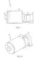
- piston 10 is illustrated in Figs. 1 and 1A and comprises a hollow piston body 12, an actuator arm 14, a piston head 16 and a connection rod 17.
- the hollow piston body 12 is integrally formed and axially aligned with the actuator arm 14 along an axis A.
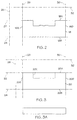
- the hollow piston body 12 and the actuator arm 14 are integrally formed from a preformed blank 18 of metallic material shown in Fig. 2.
- the blank 18 of metallic material is formed from a generally rectangular block 20 of metallic material shown in Fig. 3.
- the block 20 comprises first and second surfaces 20A, 20B forming planes 22, 24 extending into the drawing and are generally perpendicular to a first axis 26.
- the block 20 also comprises third and fourth surfaces 20C, 20D forming planes 28, 30 extending into the drawing and are generally perpendicular to a second axis 32.
- the first axis 26 is substantially perpendicular to the second axis 32.
- the blank 18 is formed by removing a central portion 20E from the block 20 through the first side 20A.
- a cavity 34 is formed with a pair of ribs 36, 38 extending therein.
- the ribs 36, 38 are spaced and sized to aid in the formation of a corresponding pair of connector rods 17 as described herein.
- the blank 18 includes first and second surfaces 18A, 18B forming the planes 22, 24 and third and forth surfaces 18C, 18D forming the planes 28, 30.
- the hollow piston body 12 and the actuator arm 14 may be formed from other blanks of metallic material having a variety of shapes and configurations.
- the blank 18 of metallic material comprises 4000 series aluminum. It will be appreciated by those skilled in the art that the blank 18 may also comprise other suitable metals and alloys as required for given applications.
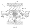
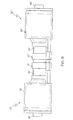
- a pair of interconnected first and second pistons 10', 10" are formed using a split die assembly 40 and working the blank 18 of metallic material along the first axis 30 and then working the blank 18 along the second axis 32.
- the pair of interconnected first and second pistons 10', 10" comprise interconnected first and second actuator arms 14', 14", first and second hollow piston bodies, 12', 12", first and second piston heads 16', 16" and first and connection rods 17', 17".
- the first and second axes 30, 32 referenced in Figs. 2 and 3 correspond to the axes of working of the blank 18 within the die assembly 40 illustrated in Figs. 4-7.
- the split die assembly 40 comprises a first stationary portion 42, a second moveable portion 44, a first punch 46 and a second punch 48.
- the second portion 44 of the die assembly 40 moves relative to the first portion 42 along the first axis 30 while the first and second punches 46, 48 move towards each other along the second axis 32.
- the first portion 42 of the die assembly 40 includes a first die block 52 and the second portion 44 of the die assembly 40 includes a second die block 54.
- the first and second die blocks 52, 54 are aligned with each other and together form a cavity (not referenced) having a shape corresponding to the shape of the interconnected first and second actuator arms 14', 14".
- the first die block 52 is centered within the first portion 42 of the die assembly 40 and positioned between third and fourth die blocks 56, 58.
- the second die block 54 is centered within the second portion 44 of the die assembly 40 and positioned between fifth and sixth die blocks 60, 62.
- the third and fifth die blocks 56, 60 are aligned with each other and together form a cavity 64 having a diameter corresponding to an outer diameter of the first hollow piston body 12'.
- the fourth and sixth die blocks 58, 60 are aligned with each other and together form a cavity 66 having a diameter corresponding to an outer diameter of the second hollow piston body 12".
- the blank 18 is positioned over the first die block 52 within the first portion 42 of the die assembly 40.
- the second portion 44 of the die assembly 40 is aligned with the first portion 42 by a pair of guide posts (not shown) and moved towards the first portion 42 along the first axis 30 by a hydraulic press (not shown) thereby working the blank 18 between the first, second, third, fourth, fifth and sixth die blocks 52, 54, 56, 58, 60, 62.
- the interconnected first and second actuator arms 14', 14" are thus formed between the first and second die blocks 52, 54.
- the first and second hollow piston bodies 12', 12" are also partially formed within the cavities 64, 66 as portions of the blank 18 within the cavities 64, 66 are slightly rounded between the third, fourth, fifth and sixth die blocks 56, 58, 60, 62.
- first and second hollow piston bodies 12', 12" can be formed without partially rounding or otherwise processing the portions of the blank 18 within the cavities 64, 66 as the blank 18 is worked along the first axis 30.
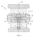
- the first and second punches 46, 48 are inserted into the cavities 64, 66 and engage respective portions of the blank 18. As illustrated in Fig. 7, the first and second punches 46, 48 are inserted into the cavities 64, 66 with the second portion 44 of the die assembly 40 fully engaged with the first portion 42 (i.e., with the die assembly 40 closed). The first and second punches 46, 48 are driven towards each other along the second axis 32 by hydraulic presses (not shown). The first and second punches 46, 48 work the respective portions of the blank 46, 48 thereby causing the first and second hollow piston bodies 12', 12" to be back extruded over the punches 46, 48.
- a first portion 46A of the first punch 46 has a diameter corresponding to the inner diameter of the first hollow piston body 12' while a first portion 48A of the second punch 48 has a diameter corresponding to the inner diameter of the second hollow piston body 12".
- a second portion 46B of the first punch 46 and a second portion 48B of the second punch 48 each have a diameter corresponding to the diameter of each respective cavity 64, 66 so as to maintain the proper position of each punch 46, 48 within the die assembly 40 during the back extrusion process. It should be apparent that the thickness of the first and second hollow piston bodies 12', 12" is controlled by the diameters of the cavities 64, 66 and the diameters of the first portions 46A, 48A of the first and second punches 46, 48.
- the first and second hollow piston bodies 12', 12" are completely formed once the first and second punches 46, 48 are fully extended within the cavities 64, 66.
- the first actuator arm 14' is axially aligned and integral with the first hollow piston body 12' while the second actuator arm 14" is axially aligned and integral with the second hollow piston body 12" as the actuator arms 14', 14" and the piston bodies 12', 12" are formed from the same blank 18 of metallic material.
- the first and second punches 46, 48 are removed from the cavities 64, 66 and the second portion 44 of the die assembly 40 is disengaged from the first portion 42 exposing the interconnected first and second pistons 10', 10".
- the interconnected first and second pistons 10', 10" are forced out of the first portion 42 by pins 68.
- first and second pistons 10', 10" are separated from each other, for example by sawing the actuator arms 14', 14" between the connection rods 17', 17".
- the piston heads 16', 16" are then welded to the first and second hollow piston bodies 12', 12", respectively thereby forming two separate pistons.
- the piston head 16 includes a base portion 70 having a button portion 72 extending from a first surface 16A thereof and an annular ring 74 extending from a second surface 16B thereof.
- a shoulder 16C is formed between the annular ring 72 and the base portion 70.
- the base portion 70 has a diameter corresponding to the outer diameter of the hollow piston body 12 while the annular ring 72 has an outer diameter corresponding the inner diameter of hollow piston body 12.
- the shoulder 16C of the piston head 16 thus engages the hollow piston body 12 with the annular ring 74 maintaining the orientation of the piston head 16 within the hollow piston body 12 prior to welding.
- the pistons are then machined as required.
- piston head 16 may be attached to the hollow piston body 12 using other suitable methods.
- the piston head 16 comprises 6000 series aluminum.
- the piston head 16 may also comprise other suitable metals and alloys as required for a given application.
Landscapes
- Engineering & Computer Science (AREA)
- Mechanical Engineering (AREA)
- General Engineering & Computer Science (AREA)
- Manufacturing & Machinery (AREA)
- Forging (AREA)
- Compressors, Vaccum Pumps And Other Relevant Systems (AREA)
- Pistons, Piston Rings, And Cylinders (AREA)
Claims (22)
- Processus pour former un piston (10) ayant un bras actionneur en un seul bloc (14), ledit processus comportant les étapes consistant à :fournir une ébauche (18) de matériau métallique,usiner ladite ébauche (18) de matériau métallique le long d'un premier axe (30) en opposant des première et seconde parties (42, 44) d'un ensemble formant matrice segmentée (40), de manière à former au moins un bras actionneur (14), etusiner ladite ébauche (18) de matériau métallique le long d'un second axe (32), ledit ensemble formant matrice segmentée (40) étant toujours fermé de manière à former au moins un corps de piston creux (12) aligné axialement avec ledit au moins un bras actionneur (14), et formé en un seul bloc avec celui-ci.
- Processus selon la revendication 1, dans lequel ladite étape consistant à usiner ladite ébauche (18) de matériau métallique le long d'un premier axe (30) de manière à former au moins un bras actionneur (14) comporte l'étape consistant à usiner ladite ébauche (18) de matériau métallique le long dudit premier axe (30) de manière à former des premier et second bras actionneurs connectés mutuellement (14', 14"), et dans lequel ladite étape consistant à usiner ladite ébauche (18) de matériau métallique le long d'un second axe (32) de manière à former au moins un corps de piston creux (12) aligné axialement avec ledit au moins un bras actionneur (14), et formé en un seul bloc avec celui-ci, comporte l'étape consistant à usiner ladite ébauche (18) de matériau métallique le long dudit second axe (32) de manière à former un premier corps de piston creux (12') aligné axialement avec ledit premier bras actionneur (14'), et formé en un seul bloc avec celui-ci, et un second corps de piston creux (12") aligné axialement avec ledit second bras actionneur (14"), et formé en un seul bloc avec celui-ci.
- Processus selon la revendication 2, comportant de plus les étapes consistant à accoupler une première tête de piston (16') avec le premier corps de piston creux (12'), et à accoupler une seconde tête de piston (16") avec ledit second corps de piston creux (12").
- Processus selon la revendication 3, dans lequel ladite étape consistant à accoupler une première tête de piston (16') avec ledit premier corps de piston creux (12') comportent l'étape consistant à souder ladite première tête de piston (16') sur ledit premier corps de piston creux (12'), et dans lequel ladite étape consistant à accoupler une seconde tête de piston (16") avec ledit second corps de piston creux (12") comporte l'étape consistant à souder ladite seconde tête de piston (16") sur ledit second corps de piston creux (12").
- Processus selon la revendication 2, comportant de plus l'étape consistant à séparer lesdits premier et second bras actionneurs connectés mutuellement (14', 14").
- Processus selon la revendication 5, dans lequel ladite étape consistant à séparer lesdits premier et second bras actionneurs connectés mutuellement (14', 14") comporte l'étape consistant à sectionner ladite ébauche (18) de matériau métallique entre lesdits premier et second bras actionneurs connectés mutuellement (14', 14").
- Processus selon la revendication 1, dans lequel ladite étape consistant à usiner ladite ébauche (18) de matériau métallique le long d'un premier axe (30) de manière à former au moins un bras actionneur (14) comporte les étapes consistant à :positionner ladite ébauche (18) de matériau métallique dans ladite première partie (42) dudit ensemble formant matrice segmentée (14), ladite première partie (42) dudit ensemble formant matrice segmentée (40) étant stationnaire,positionner ladite seconde partie (44) dudit ensemble formant matrice segmentée (40) au-dessus de ladite première partie (42) dudit ensemble formant matrice segmentée (40), lesdites première et seconde parties (42, 44) dudit ensemble formant matrice segmentée (40) formant une cavité (64, 66), une première partie de ladite cavité ayant une forme correspondant à une forme dudit au moins un bras actionneur (14), etappliquer une pression sur ladite seconde partie (44) dudit ensemble formant matrice segmentée (40) le long dudit premier axe (30), en poussant ainsi ladite seconde partie (44) dudit ensemble formant matrice segmentée (40) vers ladite première partie (42) dudit ensemble formant matrice segmentée (40), et à usiner ladite ébauche (18) de matériau métallique entre lesdites première et seconde parties (42, 44) dudit ensemble formant matrice segmentée (40).
- Processus selon la revendication 7, dans lequel ladite étape consistant à usiner ladite ébauche (18) de matériau métallique le long d'un second axe (32) de manière à former au moins un corps de piston creux (12) aligné axialement avec ledit au moins un bras actionneur (14), et formé en un seul bloc avec celui-ci, comporte les étapes consistant à :insérer au moins un poinçon (46 ou 48) à travers une deuxième partie de ladite cavité (64, 66) dudit ensemble formant matrice segmentée (40), ladite deuxième partie de ladite cavité (64, 66) étant positionnée sensiblement adjacente à ladite première partie de ladite cavité, et ayant un diamètre correspondant à un diamètre extérieur dudit au moins un corps de piston creux (12), ledit au moins un poinçon (46 ou 48) ayant un diamètre correspondant à un diamètre intérieur dudit au moins un corps de piston creux (12), etappliquer une pression à l'aide dudit au moins un poinçon (46 ou 48) le long dudit second axe (32) sur ladite ébauche (18) de matériau métallique, en extrudant ainsi avec remontée de matière ledit au moins un corps de piston creux (12) au-dessus dudit au moins un poinçon (46 ou 48).
- Processus selon la revendication 8, dans lequel lesdites étapes consistant à insérer au moins un poinçon (46 ou 48) à travers la deuxième partie de ladite cavité (64, 66) dudit ensemble formant matrice segmentée (40) et à appliquer une pression à l'aide dudit au moins un poinçon (46 ou 48) le long dudit second axe (32) sur ladite ébauche (18) de matériau métallique sont effectuées en ayant la seconde partie (44) dudit ensemble formant matrice segmentée (40) venant en prise avec ladite première partie (42) dudit ensemble formant matrice segmentée (40).
- Processus selon la revendication 1, dans lequel ladite étape consistant à fournir une ébauche (18) de matériau métallique comporte les étapes consistant à :fournir un bloc (20) de matériau métallique ayant des première et deuxième surfaces (20A, 20B) formant des plans (22, 24) qui sont généralement perpendiculaires audit premier axe (30), et des troisième et quatrième surfaces (20C, 20D) formant des plans (28, 30) qui sont généralement perpendiculaires audit second axe (32), etenlever une partie centrale (20E) dudit bloc de matériau métallique le long de ladite première surface (20A) dudit bloc de matériau métallique.
- Processus selon la revendication 10, dans lequel ladite étape consistant à enlever une partie centrale (20E) dudit bloc de matériau métallique le long de ladite première surface (20A) dudit bloc (20) de métal comporte l'étape consistant à former une pluralité d'encoches, en formant ainsi au moins une paire de nervures généralement symétriques (36, 38).
- Processus selon la revendication 1, dans lequel ladite ébauche (18) de matériau métallique comporte de l'aluminium.
- Processus pour former une paire de pistons (10', 10") ayant des bras actionneurs en un seul bloc (14', 14"), ledit processus comportant les étapes consistant à :fournir une ébauche (18) de matériau métallique,usiner ladite ébauche (18) de matériau métallique le long d'un premier axe (30) en opposant des première et seconde parties (42, 44) d'un ensemble formant matrice segmentée (40) de manière à former des premier et second bras actionneurs connectés mutuellement (14', 14"),usiner ladite ébauche (18) de matériau métallique le long d'un second axe (32), ledit ensemble formant matrice segmentée (40) étant toujours fermé, de manière à former un premier corps de piston creux (12') aligné axialement avec ledit premier bras actionneur (14'), et en un seul bloc avec celui-ci, et un second corps de piston creux (12") aligné axialement avec ledit second bras actionneur (14"), et un seul bloc avec celui-ci,accoupler une première tête de piston (16') avec ledit premier corps de piston creux (12'), et accoupler une seconde tête de piston (16") avec ledit second corps de piston creux (12"), etséparer lesdits premier et second bras actionneurs connectés mutuellement (14', 14") en formant ainsi un premier piston (10') ayant ledit premier corps de piston creux (12') aligné axialement avec ledit premier bras actionneur (14'), et un seul bloc avec celui-ci, et un second piston (10") ayant ledit second corps de piston creux (12") aligné axialement avec ledit second bras actionneur (14"), et un seul bloc avec celui-ci.
- Processus selon la revendication 13, dans lequel ladite étape consistant à accoupler une première tête de piston (16') avec ledit premier corps de piston creux (12') comporte l'étape consistant à souder ladite première tête de piston (16') sur ledit premier corps de piston creux (12'), et dans lequel ladite étape consistant à accoupler une seconde tête de piston (16") sur ledit second corps de piston creux (12") comporte l'étape consistant à souder ladite seconde tête de piston (16") sur ledit second corps de piston creux (12").
- Processus selon la revendication 13, dans lequel ladite étape consistant à séparer lesdits premier et second bras actionneurs connectés mutuellement (14', 14") comporte l'étape consistant à sectionner ladite ébauche (18) de matériau métallique entre lesdits premier et second bras actionneurs connectés mutuellement (14', 14").
- Processus selon la revendication 13, dans lequel ladite étape consistant à séparer lesdits premier et second bras actionneurs connectés mutuellement (14', 14") est effectuée avant lesdites étapes consistant à accoupler une première tête de piston (16') avec le premier corps de piston creux (12'), et à accoupler une seconde tête de piston (16") avec ledit second corps de piston creux (12").
- Processus selon la revendication 13, dans lequel ladite étape consistant à usiner ladite ébauche (18) de matériau métallique le long dudit premier axe (30), en formant ainsi des premier et second bras actionneurs connectés mutuellement (14', 14"), comporte les étapes consistant à :positionner ladite ébauche (18) de matériau métallique dans une première partie (42) d'un ensemble formant matrice segmentée (40), ladite première partie (42) dudit ensemble formant matrice segmentée (40) étant stationnaire,positionner une seconde partie (44) dudit ensemble formant matrice segmentée (40) au-dessus de ladite première partie (42) dudit ensemble formant matrice segmentée (44), lesdites première et seconde parties (42, 44) dudit ensemble formant matrice segmentée (40) formant une cavité (64, 66), une première partie de ladite cavité (64, 66) ayant une forme correspondant à une forme desdits premier et second bras actionneurs connectés mutuellement (14', 14"), etappliquer uns pression sur ladite seconde partie (44) dudit ensemble formant matrice segmentée (40) le long dudit premier axe (30), en poussant ainsi ladite seconde partie (44) dudit ensemble formant matrice segmentée (40) vers ladite première partie (42) dudit ensemble formant matrice segmentée (40), et à usiner ladite ébauche (18) de matériau métallique entre lesdites première et seconde parties (42, 44) dudit ensemble formant matrice segmentée (40).
- Processus selon la revendication 17, dans lequel ladite étape consistant à usiner ladite ébauche (18) de matériau métallique le long dudit second axe (32), en formant ainsi un premier corps de piston creux (12') et un second corps de piston creux (12"), comporte les étapes consistant à :insérer des premier et second poinçons (46, 48) à travers des deuxième et troisième parties de ladite cavité (64, 66) dudit ensemble formant matrice segmentée (40), lesdites deuxième et troisième parties de ladite cavité (64, 66) étant positionnées sensiblement adjacentes à des extrémités opposées de ladite première partie de ladite cavité (64, 66), et ayant un diamètre correspondant à un diamètre extérieur desdits premier et second corps de piston creux (12', 12"), respectivement, lesdits premier et second poinçons (46, 48) ayant un diamètre correspondant à un diamètre intérieur desdits premier et second corps de piston creux (12', 12"), etappliquer une pression à l'aide desdits premier et second poinçons (46, 48) le long dudit second axe (32) sur ladite ébauche (18) de matériau métallique, en extrudant ainsi avec remontée de matière lesdits premier et second corps de piston creux (12', 12") au-dessus desdits premier et second poinçons (46, 48), respectivement.
- Processus selon la revendication 18, dans lequel lesdites étapes consistant à insérer des premier et second poinçons (46, 48) à travers des deuxième et troisième parties de ladite cavité (64, 66) dudit ensemble formant matrice segmentée (40), et à appliquer une pression à l'aide desdits premier et second poinçons (46, 48) le long dudit second axe (32) sur les extrémités de ladite ébauche (18) de matériau métallique sont effectuées en ayant ladite seconde partie (44) dudit ensemble formant matrice segmentée (40) venant en prise avec ladite première partie dudit ensemble formant matrice segmentée.
- Processus selon la revendication 13, dans lequel ladite étape consistant à fournir une ébauche (18) de matériau métallique comporte les étapes consistant à :fournir un bloc (20) de matériau métallique ayant des première et deuxième surfaces (20A, 20B) formant des plans (22, 24) qui sont généralement perpendiculaires audit premier axe (30), et des troisième et quatrième surfaces (20C, 20D) généralement perpendiculaires audit second axe (32), etenlever une partie centrale (20E) dudit bloc de matériau métallique le long de ladite première surface (20A) dudit bloc de matériau métallique.
- Processus selon la revendication 20, dans lequel ladite étape consistant à enlever une partie centrale (20E) dudit bloc de matériau métallique comporte l'étape consistant à former une pluralité d'encoches, en formant ainsi au moins une paire de nervures généralement symétriques (36, 38).
- Processus selon la revendication 13, dans lequel ladite ébauche (18) de matériau métallique comporte de l'aluminium.
Applications Claiming Priority (3)
| Application Number | Priority Date | Filing Date | Title |
|---|---|---|---|
| US09/243,178 US6266878B1 (en) | 1999-02-02 | 1999-02-02 | Process for producing variable displacement compressor pistons having hollow piston bodies and integral actuator rods |
| US243178 | 1999-02-02 | ||
| PCT/US2000/000266 WO2000045988A1 (fr) | 1999-02-02 | 2000-01-06 | Procede de production de pistons de compresseurs a cylindree variable possedant des corps de pistons creux et des tiges de commande integrees |
Publications (2)
| Publication Number | Publication Date |
|---|---|
| EP1150799A1 EP1150799A1 (fr) | 2001-11-07 |
| EP1150799B1 true EP1150799B1 (fr) | 2002-10-02 |
Family
ID=22917647
Family Applications (1)
| Application Number | Title | Priority Date | Filing Date |
|---|---|---|---|
| EP00903135A Expired - Lifetime EP1150799B1 (fr) | 1999-02-02 | 2000-01-06 | Procede de production de pistons de compresseurs a cylindree variable possedant des corps de pistons creux et des tiges de commande integrees |
Country Status (6)
| Country | Link |
|---|---|
| US (1) | US6266878B1 (fr) |
| EP (1) | EP1150799B1 (fr) |
| AT (1) | ATE225230T1 (fr) |
| CA (1) | CA2361533A1 (fr) |
| DE (1) | DE60000535T2 (fr) |
| WO (1) | WO2000045988A1 (fr) |
Families Citing this family (15)
| Publication number | Priority date | Publication date | Assignee | Title |
|---|---|---|---|---|
| KR100302852B1 (ko) * | 1999-03-20 | 2001-10-29 | 신영주 | 압축기용 중공 피스톤 제조방법 |
| JP2000345963A (ja) * | 1999-05-31 | 2000-12-12 | Toyota Autom Loom Works Ltd | 片頭式ピストン製造用素材の製造方法 |
| JP3928336B2 (ja) * | 1999-09-21 | 2007-06-13 | 株式会社豊田自動織機 | 圧縮機用ピストンの製造方法 |
| JP2001227465A (ja) * | 2000-02-18 | 2001-08-24 | Toyota Autom Loom Works Ltd | 圧縮機用中空ピストンの製造方法 |
| JP3777942B2 (ja) | 2000-03-15 | 2006-05-24 | 株式会社豊田自動織機 | 圧縮機用中空ピストンの製造方法 |
| US6353987B1 (en) * | 2000-06-09 | 2002-03-12 | Clever Fellows Innovation Consortium, Inc. | Methods relating to constructing reciprocator assembly |
| JP4132606B2 (ja) * | 2000-08-16 | 2008-08-13 | 株式会社豊田自動織機 | 圧縮機用ピストンの製造方法 |
| JP2002250276A (ja) * | 2001-02-23 | 2002-09-06 | Toyota Industries Corp | 圧縮機におけるピストン製造方法及びピストン製造装置 |
| DE10113629A1 (de) * | 2001-03-21 | 2002-10-02 | Thyssen Krupp Automotive Ag | Verfahren zur Herstellung von Kolben- bzw. Kolbenbauteilen sowie Schmiedewerkzeug |
| DE102005041000B4 (de) * | 2005-08-29 | 2012-07-05 | Thyssenkrupp Automotive Ag | Verfahren, Fertigungslinie und Kolbenrohling zum Herstellen eines einteilig ausgebildeten Kolbens für Verbrennungsmotoren, sowie Kolben für Verbrennungsmotoren |
| CN106062362A (zh) * | 2013-12-26 | 2016-10-26 | 阿塞里克股份有限公司 | 用于在往复式压缩机中使用的活塞头及其生产方法 |
| EP3551883A1 (fr) | 2016-12-06 | 2019-10-16 | Mahle International GmbH | Procédé de fabrication de pistons à cylindrée variable |
| DE102017001384A1 (de) * | 2017-02-13 | 2018-08-16 | Neuman Aluminium Fliesspresswerk Gmbh | Verfahren zur Bildung eines Formteils und Formteil |
| JP6555393B2 (ja) * | 2018-06-18 | 2019-08-07 | 日本製鉄株式会社 | 鍛造クランク軸の製造方法 |
| CN109531068B (zh) * | 2018-12-17 | 2020-08-25 | 郑州煤矿机械集团股份有限公司 | 一种深孔活塞杆深孔与外圆同轴度控制方法 |
Family Cites Families (15)
| Publication number | Priority date | Publication date | Assignee | Title |
|---|---|---|---|---|
| US1946117A (en) | 1929-11-18 | 1934-02-06 | Charles H Bickell | Method of and apparatus for extruding valves and multiflanged pipe fittings |
| US2513710A (en) | 1945-01-20 | 1950-07-04 | Charles A Brauchler | Press-forging apparatus |
| DE974022C (de) | 1955-06-19 | 1960-08-18 | Mahle Kg | Verfahren zum gleichzeitigen Herstellen von zwei Topfkolben |
| US3305918A (en) * | 1963-03-19 | 1967-02-28 | Universal American Corp | Method of producing composite castforged aluminum piston with bonded ferrous ring carrier |
| US4321818A (en) | 1979-10-03 | 1982-03-30 | Kawaski Yukon Kabushiki Kaisha | Closed forging press |
| US4356612A (en) | 1980-03-31 | 1982-11-02 | Cameron Iron Works, Inc. | Method of producing a forged product |
| US4404262A (en) * | 1981-08-03 | 1983-09-13 | International Harvester Co. | Composite metallic and refractory article and method of manufacturing the article |
| JPS5877736A (ja) | 1981-11-05 | 1983-05-11 | Yukihiko Uchida | ピストンの製造方法 |
| JPS60168960A (ja) | 1984-02-10 | 1985-09-02 | Toshiba Corp | ボ−ルジヨイント形ピストンの製造方法 |
| EP0220031B1 (fr) | 1985-10-16 | 1990-12-19 | Nippondenso Co., Ltd. | Procédé et appareil de forgeage |
| GB9304528D0 (en) * | 1993-03-05 | 1993-04-21 | T & N Technology Ltd | Piston with cavity |
| DE4434441C2 (de) | 1994-09-27 | 1997-01-09 | Daimler Benz Ag | Vorrichtung zum Herstellen von Hohlkörpern nach dem Innenhochdruckumform-Verfahren |
| JP3695724B2 (ja) | 1996-03-19 | 2005-09-14 | カルソニックカンセイ株式会社 | 斜板式コンプレッサの片頭式ピストンの製造方法 |
| EP0809050B1 (fr) * | 1996-05-20 | 2003-08-13 | Yamaha Hatsudoki Kabushiki Kaisha | Procédé de fabrication d'un piston pour un moteur à combustion interne |
| DE19620167C2 (de) * | 1996-05-20 | 1998-11-12 | Brueninghaus Hydromatik Gmbh | Hohlkolben mit radial verschweißtem Deckel |
-
1999
- 1999-02-02 US US09/243,178 patent/US6266878B1/en not_active Expired - Lifetime
-
2000
- 2000-01-06 CA CA002361533A patent/CA2361533A1/fr not_active Abandoned
- 2000-01-06 AT AT00903135T patent/ATE225230T1/de not_active IP Right Cessation
- 2000-01-06 EP EP00903135A patent/EP1150799B1/fr not_active Expired - Lifetime
- 2000-01-06 DE DE60000535T patent/DE60000535T2/de not_active Expired - Lifetime
- 2000-01-06 WO PCT/US2000/000266 patent/WO2000045988A1/fr active IP Right Grant
Also Published As
| Publication number | Publication date |
|---|---|
| US6266878B1 (en) | 2001-07-31 |
| WO2000045988A1 (fr) | 2000-08-10 |
| EP1150799A1 (fr) | 2001-11-07 |
| CA2361533A1 (fr) | 2000-08-10 |
| DE60000535D1 (de) | 2002-11-07 |
| ATE225230T1 (de) | 2002-10-15 |
| DE60000535T2 (de) | 2003-08-14 |
Similar Documents
| Publication | Publication Date | Title |
|---|---|---|
| EP1150799B1 (fr) | Procede de production de pistons de compresseurs a cylindree variable possedant des corps de pistons creux et des tiges de commande integrees | |
| US5027996A (en) | Method of manufacturing a hollow shaft with internal swellings of revolution and shaft obtained by this method | |
| EP1792672A1 (fr) | Bague de chemin de roulement pour roulement a billes radial, procede de fabrication de celle-ci ainsi que procede et dispositif de fabrication d'une bague a haute precision | |
| KR101808998B1 (ko) | 금속 단부 단면 외주의 가공 방법 및 그 가공 방법에 의해서 얻어지는 금속 부품과 타부재의 접합 방법 | |
| EP1134412A3 (fr) | Procédé et machine de production d'un piston creux pour un compresseur par forgeage | |
| US7251979B2 (en) | Method of producing forged part and method of producing suspension arm for automotive vehicles | |
| JP2002273543A (ja) | 軸付きパーキングギヤ及びその軸付きパーキングギヤの製造方法 | |
| CA1114779A (fr) | Methode et dispositif de faconnage par extrusion de tiges metalliques | |
| KR101473948B1 (ko) | 플랜지 구조체의 제조 방법 | |
| JPH0261342B2 (fr) | ||
| KR930008590B1 (ko) | 아이조인트용 단부 이음쇠의 제조방법 | |
| US4677722A (en) | Tapered piston pin | |
| EP3037189B1 (fr) | Forgeage de précision pour blocs d'extrémités fluidiques | |
| CN113787162A (zh) | 六角法兰面螺栓的加工装置及其成型加工方法 | |
| CN1079715C (zh) | 摆板式压缩机承接板的制造方法 | |
| CN111069414B (zh) | 零件冲孔加工装置及方法 | |
| KR0174782B1 (ko) | 봉부재의 헤드부 홈 냉간단조방법 | |
| JPH0360839A (ja) | 等速ジョイント外輪の製造方法および製造装置 | |
| CN114932185B (zh) | 空心球冷墩工艺 | |
| JPH0516931B2 (fr) | ||
| CN216540702U (zh) | 六角法兰面螺栓的加工装置及其六角法兰面螺栓 | |
| KR0128496B1 (ko) | 커넥팅 로드의 파단분할 방법 및 그 장치 | |
| WO2004109065A1 (fr) | Culbuteur et procede de production | |
| KR20050029091A (ko) | 인너튜브 제조 방법 및 장치 | |
| JP2004034040A (ja) | 鍛造用金型 |
Legal Events
| Date | Code | Title | Description |
|---|---|---|---|
| PUAI | Public reference made under article 153(3) epc to a published international application that has entered the european phase |
Free format text: ORIGINAL CODE: 0009012 |
|
| 17P | Request for examination filed |
Effective date: 20010827 |
|
| AK | Designated contracting states |
Kind code of ref document: A1 Designated state(s): AT BE CH CY DE DK ES FI FR GB GR IE IT LI LU MC NL PT SE |
|
| GRAG | Despatch of communication of intention to grant |
Free format text: ORIGINAL CODE: EPIDOS AGRA |
|
| 17Q | First examination report despatched |
Effective date: 20020207 |
|
| GRAG | Despatch of communication of intention to grant |
Free format text: ORIGINAL CODE: EPIDOS AGRA |
|
| GRAH | Despatch of communication of intention to grant a patent |
Free format text: ORIGINAL CODE: EPIDOS IGRA |
|
| GRAH | Despatch of communication of intention to grant a patent |
Free format text: ORIGINAL CODE: EPIDOS IGRA |
|
| GRAA | (expected) grant |
Free format text: ORIGINAL CODE: 0009210 |
|
| AK | Designated contracting states |
Kind code of ref document: B1 Designated state(s): AT BE CH CY DE DK ES FI FR GB GR IE IT LI LU MC NL PT SE |
|
| PG25 | Lapsed in a contracting state [announced via postgrant information from national office to epo] |
Ref country code: CH Free format text: LAPSE BECAUSE OF FAILURE TO SUBMIT A TRANSLATION OF THE DESCRIPTION OR TO PAY THE FEE WITHIN THE PRESCRIBED TIME-LIMIT Effective date: 20021002 Ref country code: BE Free format text: LAPSE BECAUSE OF FAILURE TO SUBMIT A TRANSLATION OF THE DESCRIPTION OR TO PAY THE FEE WITHIN THE PRESCRIBED TIME-LIMIT Effective date: 20021002 Ref country code: AT Free format text: LAPSE BECAUSE OF FAILURE TO SUBMIT A TRANSLATION OF THE DESCRIPTION OR TO PAY THE FEE WITHIN THE PRESCRIBED TIME-LIMIT Effective date: 20021002 Ref country code: LI Free format text: LAPSE BECAUSE OF FAILURE TO SUBMIT A TRANSLATION OF THE DESCRIPTION OR TO PAY THE FEE WITHIN THE PRESCRIBED TIME-LIMIT Effective date: 20021002 Ref country code: FI Free format text: LAPSE BECAUSE OF FAILURE TO SUBMIT A TRANSLATION OF THE DESCRIPTION OR TO PAY THE FEE WITHIN THE PRESCRIBED TIME-LIMIT Effective date: 20021002 Ref country code: GR Free format text: LAPSE BECAUSE OF FAILURE TO SUBMIT A TRANSLATION OF THE DESCRIPTION OR TO PAY THE FEE WITHIN THE PRESCRIBED TIME-LIMIT Effective date: 20021002 |
|
| REF | Corresponds to: |
Ref document number: 225230 Country of ref document: AT Date of ref document: 20021015 Kind code of ref document: T |
|
| REG | Reference to a national code |
Ref country code: GB Ref legal event code: FG4D |
|
| REG | Reference to a national code |
Ref country code: CH Ref legal event code: EP |
|
| REG | Reference to a national code |
Ref country code: IE Ref legal event code: FG4D |
|
| REF | Corresponds to: |
Ref document number: 60000535 Country of ref document: DE Date of ref document: 20021107 |
|
| ET | Fr: translation filed | ||
| PG25 | Lapsed in a contracting state [announced via postgrant information from national office to epo] |
Ref country code: PT Free format text: LAPSE BECAUSE OF FAILURE TO SUBMIT A TRANSLATION OF THE DESCRIPTION OR TO PAY THE FEE WITHIN THE PRESCRIBED TIME-LIMIT Effective date: 20030102 Ref country code: DK Free format text: LAPSE BECAUSE OF FAILURE TO SUBMIT A TRANSLATION OF THE DESCRIPTION OR TO PAY THE FEE WITHIN THE PRESCRIBED TIME-LIMIT Effective date: 20030102 Ref country code: SE Free format text: LAPSE BECAUSE OF FAILURE TO SUBMIT A TRANSLATION OF THE DESCRIPTION OR TO PAY THE FEE WITHIN THE PRESCRIBED TIME-LIMIT Effective date: 20030102 |
|
| PG25 | Lapsed in a contracting state [announced via postgrant information from national office to epo] |
Ref country code: IE Free format text: LAPSE BECAUSE OF NON-PAYMENT OF DUE FEES Effective date: 20030106 Ref country code: CY Free format text: LAPSE BECAUSE OF FAILURE TO SUBMIT A TRANSLATION OF THE DESCRIPTION OR TO PAY THE FEE WITHIN THE PRESCRIBED TIME-LIMIT Effective date: 20030106 |
|
| PG25 | Lapsed in a contracting state [announced via postgrant information from national office to epo] |
Ref country code: MC Free format text: LAPSE BECAUSE OF NON-PAYMENT OF DUE FEES Effective date: 20030131 |
|
| PG25 | Lapsed in a contracting state [announced via postgrant information from national office to epo] |
Ref country code: ES Free format text: LAPSE BECAUSE OF FAILURE TO SUBMIT A TRANSLATION OF THE DESCRIPTION OR TO PAY THE FEE WITHIN THE PRESCRIBED TIME-LIMIT Effective date: 20030429 |
|
| REG | Reference to a national code |
Ref country code: CH Ref legal event code: PL |
|
| PLBE | No opposition filed within time limit |
Free format text: ORIGINAL CODE: 0009261 |
|
| STAA | Information on the status of an ep patent application or granted ep patent |
Free format text: STATUS: NO OPPOSITION FILED WITHIN TIME LIMIT |
|
| 26N | No opposition filed |
Effective date: 20030703 |
|
| REG | Reference to a national code |
Ref country code: IE Ref legal event code: MM4A |
|
| REG | Reference to a national code |
Ref country code: GB Ref legal event code: 732E |
|
| REG | Reference to a national code |
Ref country code: FR Ref legal event code: TP |
|
| NLS | Nl: assignments of ep-patents |
Owner name: ELKHART PRODUCTS CORPORATION (A DELAWARE CORPORATI Effective date: 20060118 |
|
| PGFP | Annual fee paid to national office [announced via postgrant information from national office to epo] |
Ref country code: NL Payment date: 20130110 Year of fee payment: 14 |
|
| PGFP | Annual fee paid to national office [announced via postgrant information from national office to epo] |
Ref country code: IT Payment date: 20140108 Year of fee payment: 15 |
|
| REG | Reference to a national code |
Ref country code: NL Ref legal event code: V1 Effective date: 20140801 |
|
| PG25 | Lapsed in a contracting state [announced via postgrant information from national office to epo] |
Ref country code: NL Free format text: LAPSE BECAUSE OF NON-PAYMENT OF DUE FEES Effective date: 20140801 |
|
| PGFP | Annual fee paid to national office [announced via postgrant information from national office to epo] |
Ref country code: LU Payment date: 20150206 Year of fee payment: 16 |
|
| PGFP | Annual fee paid to national office [announced via postgrant information from national office to epo] |
Ref country code: GB Payment date: 20150127 Year of fee payment: 16 |
|
| PG25 | Lapsed in a contracting state [announced via postgrant information from national office to epo] |
Ref country code: IT Free format text: LAPSE BECAUSE OF NON-PAYMENT OF DUE FEES Effective date: 20150106 |
|
| REG | Reference to a national code |
Ref country code: FR Ref legal event code: PLFP Year of fee payment: 17 |
|
| PG25 | Lapsed in a contracting state [announced via postgrant information from national office to epo] |
Ref country code: LU Free format text: LAPSE BECAUSE OF NON-PAYMENT OF DUE FEES Effective date: 20160106 |
|
| GBPC | Gb: european patent ceased through non-payment of renewal fee |
Effective date: 20160106 |
|
| PG25 | Lapsed in a contracting state [announced via postgrant information from national office to epo] |
Ref country code: GB Free format text: LAPSE BECAUSE OF NON-PAYMENT OF DUE FEES Effective date: 20160106 |
|
| REG | Reference to a national code |
Ref country code: FR Ref legal event code: PLFP Year of fee payment: 18 |
|
| REG | Reference to a national code |
Ref country code: FR Ref legal event code: PLFP Year of fee payment: 19 |
|
| PGFP | Annual fee paid to national office [announced via postgrant information from national office to epo] |
Ref country code: DE Payment date: 20190129 Year of fee payment: 20 Ref country code: FR Payment date: 20190125 Year of fee payment: 20 |
|
| REG | Reference to a national code |
Ref country code: DE Ref legal event code: R071 Ref document number: 60000535 Country of ref document: DE |