EP1523905A1 - Tisch mit klappbaren Beinen - Google Patents
Tisch mit klappbaren Beinen Download PDFInfo
- Publication number
- EP1523905A1 EP1523905A1 EP03023394A EP03023394A EP1523905A1 EP 1523905 A1 EP1523905 A1 EP 1523905A1 EP 03023394 A EP03023394 A EP 03023394A EP 03023394 A EP03023394 A EP 03023394A EP 1523905 A1 EP1523905 A1 EP 1523905A1
- Authority
- EP
- European Patent Office
- Prior art keywords
- bearing
- table top
- strut
- groove
- legs
- Prior art date
- Legal status (The legal status is an assumption and is not a legal conclusion. Google has not performed a legal analysis and makes no representation as to the accuracy of the status listed.)
- Granted
Links
Images


Classifications
-
- A—HUMAN NECESSITIES
- A47—FURNITURE; DOMESTIC ARTICLES OR APPLIANCES; COFFEE MILLS; SPICE MILLS; SUCTION CLEANERS IN GENERAL
- A47B—TABLES; DESKS; OFFICE FURNITURE; CABINETS; DRAWERS; GENERAL DETAILS OF FURNITURE
- A47B3/00—Folding or stowable tables
- A47B3/08—Folding or stowable tables with legs pivoted to top or underframe
- A47B3/091—Folding or stowable tables with legs pivoted to top or underframe with struts supporting the legs
- A47B3/0911—Folding or stowable tables with legs pivoted to top or underframe with struts supporting the legs the struts being permanently connected to top and leg or underframe and leg
Definitions
- the invention relates to the field of furniture, in particular tables with folding legs.
- a construction for attaching a folding leg to a Furniture is known for example from EP 1 050 240 A1.
- the one described there Construction is complex and complicated and illustrates impressively which Efforts are made to meet the above requirements fulfill.
- the core of the invention is the idea of the legs of the inventive table in each to a bearing body under the table top in the folding direction displaced to store, and between leg and another bearing at the bottom of the Table top a hinged at both ends strut provided.
- a hinged at both ends strut provided.
- a particularly advantageous embodiment of the core idea described lies therein, the sliding guide for the leg in the bearing body under the Design table top as a groove with a recess upwards, in which the bearing pin of the leg bearing tube slides and locks, and on one after roll up a locking ball at the top pointing oblique bridge, the at Rolled table under the journals rolls and this in the recess fixed and, with the table laid on its back, rolling away from the journal and releases this.
- This is a position-dependent gravitation-controlled fixation and solution of the legs achieved, and it eliminates otherwise necessary Measures and elements, such as Wing nuts, each solved and again must be tightened.
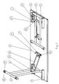
- Fig. 1 a laid on the back table top 1 is shown, at the Bottom four Beinstandrohre 4 are provided, each to two a T-foot forming leg pairs are summarized. These pairs of legs include except the Beinstandrohren 4 still each leg bearing tube 3 and the Crossbar 5.
- each a cross bar. 8 provided on which by means of the connecting screws 23 articulated a Strut 6 is stored.
- the strut 6 is shaped as a wire bow.
- the crossbar 8 prevents the removal of the wire bracket from the holes in the Leg stand tube 4.
- the other end of the strut 6 is articulated to a strut bearing 7 under the Table top 1 attached.
- the strut bearing 7 is on the table top 1 means Screw 21 is fixed, and has two opposing, elastic, from Plastic existing clamping lugs 27.
- the two leg bearing tubes 3 are with their ends in the bearing bodies 11th mounted longitudinally displaceable.
- These bearing bodies 11 are angle iron made of steel, the one with its surface with the mounting screws 20 at the bottom the table top 1 are screwed, and in the other surface a groove 24 with to the table top directed recess 25 is provided. With the bearing bodies 11 is connected via the connecting screws 22, the housing 9.
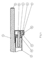
- Fig. 2 it is shown that the leg bearing tubes 3 at their ends bearing pin 15th have in the leg bearing tube 3 by means of a plastic Tube insert 16 are fixed.
- This tube insert 16 consists of the plastic PA6 with 30% glass fibers.
- a spring 12th is located, and under this spring 12 a ball 14.
- This ball 14 may be on the Leaning jetty 26 move.
- the housing 9 is made of the plastic PA6 with 30% glass fiber.
- the web 26 is formed in the housing 9. Are formed also the holders for the locking spring 12 and the brake spring thirteenth
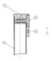
- Fig. 4 is a section through the bearing of the journal 15 is shown.
- the tube insert 16 is shown. This one is conical than inside Hollow cylinder formed, wherein the inclination of the cone shell is about 2 °.
- the tube insert 16 has the circumference on the outside of the Inner diameter of the leg bearing tube 3 an oversize, at its lower End an undersize.
- the jacket of the tube insert 16 has slots 28 and Ribs 29 on.
- the cone angle of 2 ° causes on the one hand the Frictional resistance when driving the trunnion 15 is not too large, on the other hand, a once introduced pin 15 does not fall out.
- the trunnion 15 takes the in Fig. 3rd shown position in the recess 25 of the groove 24 a. It blocks the Arresting ball 14, the bearing pin 15 in the recess 25.
- the T-foot is so stably fixed.
- the fixation or stabilization of the table is also about the weight or the load of the table top. 1
Landscapes
- Tables And Desks Characterized By Structural Shape (AREA)
- Purses, Travelling Bags, Baskets, Or Suitcases (AREA)
- Accommodation For Nursing Or Treatment Tables (AREA)
Abstract
Description
- die Beine einfach anklappbar und aufstellbar sind, und
- der Tisch im aufgestellten Zustand einen stabilen Stand hat, aber dennoch
- ein ästhetisch ansprechendes Erscheinungsbild abgibt, und
- der Tisch im gelagerten Zustand nur wenig Raum einnimmt, insbesondere beim Stapeln in die Höhe,
- der Herstellungsaufwand und damit die Produktionskosten möglichst klein sind.
- Fig.1
- einen Tisch von unten mit zwei T-Füßen, von denen der eine angeklappt und der andere aufgestellt ist,
- Fig.2
- einen Schnitt durch einen Tisch mit aufgestelltem T-Fuß,
- Fig.3
- einen Schnitt durch das Gehäuse mit Ansicht des Lagerkörpers, in welchem der Lagerzapfen seine Verschiebebewegung ausführt,
- Fig.4
- die vergrößerte Darstellung der Lagerung des Lagerzapfens im Lagerkörper,
- Fig.5
- eine Darstellung des Rohreinsatzes für den Lagerzapfen, und
- Fig.6
- die vergrößerte Darstellung des Fußgleiters am Ende des Fußquerrohres,
- 1
- Tischplatte
- 2
- Kantenschutz
- 3
- Beinlagerrohr
- 4
- Beinstandrohr
- 5
- Fußquerrohr
- 6
- Strebe
- 7
- Strebenlager
- 8
- Querriegel
- 9
- Gehäuse
- 10
- Stapelauflage
- 11
- Lagerkörper
- 12
- Arretierfeder
- 13
- Bremsfeder
- 14
- Arretierkugel
- 15
- Lagerzapfen
- 16
- Rohreinsatz
- 17
- Fußgleiter
- 18
- Fußgleiterschraube
- 19
- Befestigungsschraube für Gleiter 17
- 20
- Befestigungsschraube für Lagerkörper 11
- 21
- Befestigungsschraube für Streben lager 7
- 22
- Verbindungsschraube für Gehäuse 9
- 23
- Verbindungsschraube für Querriegel 8
- 24
- Nut
- 25
- Ausnehmung
- 26
- Schiefer Steg
- 27
- Klemmnasen
- 28
- Schlitze
- 29
- Rippen
Claims (8)
- Tisch mit anklappbaren Beinen, bei welchem mindestens zwei Beine vorgesehen sind, die gelenkig in an der Unterseite der Tischplatte (1) befestigten Lagerkörpern (11) gelagert sind, und die gelenkig mit einer Strebe (6) verbunden sind, die im aufgestellten Zustand der Beine an der Unterseite der Tischplatte (1) befestigt ist,
dadurch gekennzeichnet, dassdie Beine in den Lagerkörpern (11) in Klapprichtung im wesentlichen parallel zur Tischplatte (1) verschiebbar gelagert sind, unddie Strebe (6) an der Unterseite der Tischplatte (1) permanent gelenkig befestigt ist. - Tisch nach Anspruch 1, dadurch gekennzeichnet, dass zwei Beinpaare vorgesehen sind, die jeweils zwei an einem Beinlagerrohr (3) befestigte Beinstandrohre (4) umfassen, und die Beinlagerrohre (3) an ihren Enden jeweils einen Lagerzapfen (15) aufweisen, der gleitbar in einer Nut (24) des Lagerkörpers (11) gelagert ist, und die Nut (24) an ihrem einen Ende in Richtung zur Tischplatte (1) eine Ausnehmung (25) aufweist, in welche der Lagerzapfen (15) bei aufgestellten Beinstandrohren (4) einrastet, und eine Arretierkugel (14) vorgesehen ist, die sich auf einem schiefen Steg (26) in einem Gehäuse (9) bewegt derart, dass sie bei aufrecht stehendem Tisch unter den in die Ausnehmung (25) eingerasteten Lagerzapfen (15) zu liegen kommt, und bei auf dem Rücken liegendem Tisch auf dem schiefen Steg (26) in Richtung Tischplatte (1) rollt.
- Tisch nach Anspruch 2, dadurch gekennzeichnet, dass in dem Gehäuse (9) im Bereich der Ausnehmung (25) der Nut (24) eine Arretierfeder (12) vorgesehen ist, auf deren Unterseite die Arretierkugel (14) und auf deren Oberseite der Lagerzapfen (15) gleitet, und am anderen Ende der Nut (24) eine Bremsfeder (13), welche beim Einklappen der Beinstandrohre (4) den Aufschlag des Lagerzapfens (15) auf das Ende der Nut (24) abdämpft.
- Tisch nach Anspruch 2, dadurch gekennzeichnet, dass der Lagerkörper (11) als Stahl-Winkel ausgebildet ist, der in seiner einen Winkelfläche die Nut (24) zur Führung des Lagerzapfens (15) aufweist, und mit seiner anderen Winkelfläche an der Unterseite der Tischplatte (1) befestigt ist, und das Gehäuse (9) aus Kunststoff besteht und an dem Lagerkörper (11) angeschraubt ist, und die Strebe (6) mit den Beinstandrohren (4) gelenkig mittels eines Querriegels (8) verbunden, und an der Unterseite der Tischplatte (1) gelenkig mittels eines Strebenlagers (7) befestigt ist, welches elastische Klemmnasen (27) aus Kunststoff aufweist, zwischen welche die Beinlagerrohre (4) im angeklappten Zustand einrasten.
- Tisch nach Anspruch 2, dadurch gekennzeichnet, dass die Lagerzapfen (15) im Beinlagerrohr (3) jeweils in einen Rohreinsatz (16) klemmend eingeschlagen sind, der aus Kunststoff besteht und als zylindrischer Hohlkörper mit längs verlaufenden Schlitzen (28) im Zylindermantel ausgebildet ist, wobei der innere Hohlraum konisch mit einem Neigungswinkel zwischen 1° und 3° ausgebildet ist.
- Tisch nach Anspruch 5, dadurch gekennzeichnet, dass der Rohreinsatz (16) an seinem Kopfteil gegenüber dem Innendurchmesser des Beinlagerrohres (3) ein leichtes Übermaß, und an seinem Fußteil ein leichtes Untermaß aufweist.
- Tisch nach Anspruch 2, dadurch gekennzeichnet, dass am unteren Ende der beiden zu einem Paar verbundenen Beinstandrohre (4) in Querrichtung ein Fußquerrohr (6) vorgesehen ist, an dessen beiden Enden jeweils ein aus Kunststoff bestehender Fußgleiter (17) mit einem Innengewinde vorgesehen ist, in welches höhenverstellbar eine Fußgleiterschraube (18) eingeschraubt ist.
- Tisch nach Anspruch 7, dadurch gekennzeichnet, dass das Streben lager (7), der Querriegel (8), das Feder-Gehäuse (9) und der Rohreinsatz (16) aus Kunststoff, die Beinstandrohre (4) mit dem Beinlagerrohr (3); dem Lagerzapfen (15), dem Fußquerrohr (5) und der Strebe (6) und der Lagerkörper (11) aus Stahl, und die Arretierkugel (14) aus Stahl oder Hartgummi bestehen.
Priority Applications (4)
| Application Number | Priority Date | Filing Date | Title |
|---|---|---|---|
| ES03023394T ES2305382T3 (es) | 2003-10-16 | 2003-10-16 | Mesa con patas plegables. |
| EP03023394A EP1523905B1 (de) | 2003-10-16 | 2003-10-16 | Tisch mit klappbaren Beinen |
| AT03023394T ATE392162T1 (de) | 2003-10-16 | 2003-10-16 | Tisch mit klappbaren beinen |
| DE50309646T DE50309646D1 (de) | 2003-10-16 | 2003-10-16 | Tisch mit klappbaren Beinen |
Applications Claiming Priority (1)
| Application Number | Priority Date | Filing Date | Title |
|---|---|---|---|
| EP03023394A EP1523905B1 (de) | 2003-10-16 | 2003-10-16 | Tisch mit klappbaren Beinen |
Publications (2)
| Publication Number | Publication Date |
|---|---|
| EP1523905A1 true EP1523905A1 (de) | 2005-04-20 |
| EP1523905B1 EP1523905B1 (de) | 2008-04-16 |
Family
ID=34354473
Family Applications (1)
| Application Number | Title | Priority Date | Filing Date |
|---|---|---|---|
| EP03023394A Expired - Lifetime EP1523905B1 (de) | 2003-10-16 | 2003-10-16 | Tisch mit klappbaren Beinen |
Country Status (4)
| Country | Link |
|---|---|
| EP (1) | EP1523905B1 (de) |
| AT (1) | ATE392162T1 (de) |
| DE (1) | DE50309646D1 (de) |
| ES (1) | ES2305382T3 (de) |
Cited By (2)
| Publication number | Priority date | Publication date | Assignee | Title |
|---|---|---|---|---|
| CN110693246A (zh) * | 2019-11-03 | 2020-01-17 | 临颍县提雅童车配件厂 | 单端升降的床护栏 |
| CN111761114A (zh) * | 2020-07-31 | 2020-10-13 | 安徽双翔安全环境科技有限公司 | 一种用于剪板机生产安全的光栅保护装置 |
Citations (4)
| Publication number | Priority date | Publication date | Assignee | Title |
|---|---|---|---|---|
| US3291078A (en) * | 1965-05-20 | 1966-12-13 | Saussure William P De | Locks for legs for folding table |
| US5109778A (en) * | 1991-04-29 | 1992-05-05 | Berco Industries | Folding table |
| US5490467A (en) * | 1994-12-23 | 1996-02-13 | Howe Furniture Corporation | Folding table mechanism |
| EP1050240A1 (de) | 1999-05-06 | 2000-11-08 | Formenti & Giovenzana S.p.A. | Vorrichtung zum Verbinden eines klappbaren Stützbeines mit einem Möbelstück |
-
2003
- 2003-10-16 ES ES03023394T patent/ES2305382T3/es not_active Expired - Lifetime
- 2003-10-16 EP EP03023394A patent/EP1523905B1/de not_active Expired - Lifetime
- 2003-10-16 DE DE50309646T patent/DE50309646D1/de not_active Expired - Lifetime
- 2003-10-16 AT AT03023394T patent/ATE392162T1/de active
Patent Citations (4)
| Publication number | Priority date | Publication date | Assignee | Title |
|---|---|---|---|---|
| US3291078A (en) * | 1965-05-20 | 1966-12-13 | Saussure William P De | Locks for legs for folding table |
| US5109778A (en) * | 1991-04-29 | 1992-05-05 | Berco Industries | Folding table |
| US5490467A (en) * | 1994-12-23 | 1996-02-13 | Howe Furniture Corporation | Folding table mechanism |
| EP1050240A1 (de) | 1999-05-06 | 2000-11-08 | Formenti & Giovenzana S.p.A. | Vorrichtung zum Verbinden eines klappbaren Stützbeines mit einem Möbelstück |
Cited By (2)
| Publication number | Priority date | Publication date | Assignee | Title |
|---|---|---|---|---|
| CN110693246A (zh) * | 2019-11-03 | 2020-01-17 | 临颍县提雅童车配件厂 | 单端升降的床护栏 |
| CN111761114A (zh) * | 2020-07-31 | 2020-10-13 | 安徽双翔安全环境科技有限公司 | 一种用于剪板机生产安全的光栅保护装置 |
Also Published As
| Publication number | Publication date |
|---|---|
| EP1523905B1 (de) | 2008-04-16 |
| ES2305382T3 (es) | 2008-11-01 |
| ATE392162T1 (de) | 2008-05-15 |
| DE50309646D1 (de) | 2008-05-29 |
Similar Documents
| Publication | Publication Date | Title |
|---|---|---|
| DE3637362C2 (de) | ||
| EP0432576A2 (de) | Sonnenschirm | |
| DE102004038507A1 (de) | Rollenführung für verstellbare Fahrzeugsitze | |
| DE3412549A1 (de) | Von hand hoehenverstellbarer podestbock fuer theaterbuehnen o.dgl. | |
| EP1974633A2 (de) | Sitzmöbel | |
| DE3238889C2 (de) | ||
| EP1523905A1 (de) | Tisch mit klappbaren Beinen | |
| DE10161319B4 (de) | Trockengestellstruktur | |
| EP0457034A1 (de) | Wäscheständer mit Trocknungsrost | |
| EP1405580B1 (de) | Tisch mit klappbaren Beinen | |
| DE69807414T2 (de) | Ständer zum Auflegen von Angelruten | |
| DE102016120521B4 (de) | Klapptisch | |
| DE4005140A1 (de) | Stuetze | |
| DE102004043192B4 (de) | Tisch | |
| DE202011000580U1 (de) | Markise | |
| AT509542B1 (de) | Gelenkbeschlag für sitzmöbel | |
| DE19938192A1 (de) | Trampolin | |
| DE102008044969B3 (de) | Tischfußballtisch mit einem schwenkbar gelagerten Spielfeldtisch | |
| DE69907086T2 (de) | Zusammenklappbarer Fahrradständer | |
| CH683231A5 (de) | Vorrichtung zum Abstützen einer Arbeitsplatte. | |
| DE3303670A1 (de) | Ausziehbarer tisch | |
| DE8533632U1 (de) | Markise | |
| DE2534061A1 (de) | Tisch | |
| DE102017112428A1 (de) | Ständer für Musikinstrumente | |
| DE2717188C2 (de) | Transportable und zusammenklappbare Werkbank |
Legal Events
| Date | Code | Title | Description |
|---|---|---|---|
| PUAI | Public reference made under article 153(3) epc to a published international application that has entered the european phase |
Free format text: ORIGINAL CODE: 0009012 |
|
| AK | Designated contracting states |
Kind code of ref document: A1 Designated state(s): AT BE BG CH CY CZ DE DK EE ES FI FR GB GR HU IE IT LI LU MC NL PT RO SE SI SK TR |
|
| AX | Request for extension of the european patent |
Extension state: AL LT LV MK |
|
| 17P | Request for examination filed |
Effective date: 20050906 |
|
| AKX | Designation fees paid |
Designated state(s): AT BE BG CH CY CZ DE DK EE ES FI FR GB GR HU IE IT LI LU MC NL PT RO SE SI SK TR |
|
| GRAP | Despatch of communication of intention to grant a patent |
Free format text: ORIGINAL CODE: EPIDOSNIGR1 |
|
| GRAS | Grant fee paid |
Free format text: ORIGINAL CODE: EPIDOSNIGR3 |
|
| GRAA | (expected) grant |
Free format text: ORIGINAL CODE: 0009210 |
|
| AK | Designated contracting states |
Kind code of ref document: B1 Designated state(s): AT BE BG CH CY CZ DE DK EE ES FI FR GB GR HU IE IT LI LU MC NL PT RO SE SI SK TR |
|
| REG | Reference to a national code |
Ref country code: CH Ref legal event code: EP |
|
| REG | Reference to a national code |
Ref country code: IE Ref legal event code: FG4D Free format text: LANGUAGE OF EP DOCUMENT: GERMAN |
|
| REF | Corresponds to: |
Ref document number: 50309646 Country of ref document: DE Date of ref document: 20080529 Kind code of ref document: P |
|
| PG25 | Lapsed in a contracting state [announced via postgrant information from national office to epo] |
Ref country code: SI Free format text: LAPSE BECAUSE OF FAILURE TO SUBMIT A TRANSLATION OF THE DESCRIPTION OR TO PAY THE FEE WITHIN THE PRESCRIBED TIME-LIMIT Effective date: 20080416 |
|
| PG25 | Lapsed in a contracting state [announced via postgrant information from national office to epo] |
Ref country code: PT Free format text: LAPSE BECAUSE OF FAILURE TO SUBMIT A TRANSLATION OF THE DESCRIPTION OR TO PAY THE FEE WITHIN THE PRESCRIBED TIME-LIMIT Effective date: 20080916 Ref country code: BG Free format text: LAPSE BECAUSE OF FAILURE TO SUBMIT A TRANSLATION OF THE DESCRIPTION OR TO PAY THE FEE WITHIN THE PRESCRIBED TIME-LIMIT Effective date: 20080716 Ref country code: FI Free format text: LAPSE BECAUSE OF FAILURE TO SUBMIT A TRANSLATION OF THE DESCRIPTION OR TO PAY THE FEE WITHIN THE PRESCRIBED TIME-LIMIT Effective date: 20080416 |
|
| REG | Reference to a national code |
Ref country code: ES Ref legal event code: FG2A Ref document number: 2305382 Country of ref document: ES Kind code of ref document: T3 |
|
| REG | Reference to a national code |
Ref country code: IE Ref legal event code: FD4D |
|
| ET | Fr: translation filed | ||
| PG25 | Lapsed in a contracting state [announced via postgrant information from national office to epo] |
Ref country code: CZ Free format text: LAPSE BECAUSE OF FAILURE TO SUBMIT A TRANSLATION OF THE DESCRIPTION OR TO PAY THE FEE WITHIN THE PRESCRIBED TIME-LIMIT Effective date: 20080416 Ref country code: IE Free format text: LAPSE BECAUSE OF FAILURE TO SUBMIT A TRANSLATION OF THE DESCRIPTION OR TO PAY THE FEE WITHIN THE PRESCRIBED TIME-LIMIT Effective date: 20080416 Ref country code: SE Free format text: LAPSE BECAUSE OF FAILURE TO SUBMIT A TRANSLATION OF THE DESCRIPTION OR TO PAY THE FEE WITHIN THE PRESCRIBED TIME-LIMIT Effective date: 20080716 Ref country code: DK Free format text: LAPSE BECAUSE OF FAILURE TO SUBMIT A TRANSLATION OF THE DESCRIPTION OR TO PAY THE FEE WITHIN THE PRESCRIBED TIME-LIMIT Effective date: 20080416 |
|
| PLBE | No opposition filed within time limit |
Free format text: ORIGINAL CODE: 0009261 |
|
| STAA | Information on the status of an ep patent application or granted ep patent |
Free format text: STATUS: NO OPPOSITION FILED WITHIN TIME LIMIT |
|
| PG25 | Lapsed in a contracting state [announced via postgrant information from national office to epo] |
Ref country code: SK Free format text: LAPSE BECAUSE OF FAILURE TO SUBMIT A TRANSLATION OF THE DESCRIPTION OR TO PAY THE FEE WITHIN THE PRESCRIBED TIME-LIMIT Effective date: 20080416 Ref country code: RO Free format text: LAPSE BECAUSE OF FAILURE TO SUBMIT A TRANSLATION OF THE DESCRIPTION OR TO PAY THE FEE WITHIN THE PRESCRIBED TIME-LIMIT Effective date: 20080416 |
|
| 26N | No opposition filed |
Effective date: 20090119 |
|
| BERE | Be: lapsed |
Owner name: SEDUS STOLL A.G. Effective date: 20081031 |
|
| PG25 | Lapsed in a contracting state [announced via postgrant information from national office to epo] |
Ref country code: EE Free format text: LAPSE BECAUSE OF FAILURE TO SUBMIT A TRANSLATION OF THE DESCRIPTION OR TO PAY THE FEE WITHIN THE PRESCRIBED TIME-LIMIT Effective date: 20080416 |
|
| PG25 | Lapsed in a contracting state [announced via postgrant information from national office to epo] |
Ref country code: MC Free format text: LAPSE BECAUSE OF NON-PAYMENT OF DUE FEES Effective date: 20081031 |
|
| PG25 | Lapsed in a contracting state [announced via postgrant information from national office to epo] |
Ref country code: CY Free format text: LAPSE BECAUSE OF FAILURE TO SUBMIT A TRANSLATION OF THE DESCRIPTION OR TO PAY THE FEE WITHIN THE PRESCRIBED TIME-LIMIT Effective date: 20080416 Ref country code: BE Free format text: LAPSE BECAUSE OF NON-PAYMENT OF DUE FEES Effective date: 20081031 |
|
| PGFP | Annual fee paid to national office [announced via postgrant information from national office to epo] |
Ref country code: DE Payment date: 20091026 Year of fee payment: 7 |
|
| PG25 | Lapsed in a contracting state [announced via postgrant information from national office to epo] |
Ref country code: HU Free format text: LAPSE BECAUSE OF FAILURE TO SUBMIT A TRANSLATION OF THE DESCRIPTION OR TO PAY THE FEE WITHIN THE PRESCRIBED TIME-LIMIT Effective date: 20081017 Ref country code: LU Free format text: LAPSE BECAUSE OF NON-PAYMENT OF DUE FEES Effective date: 20081016 |
|
| PG25 | Lapsed in a contracting state [announced via postgrant information from national office to epo] |
Ref country code: TR Free format text: LAPSE BECAUSE OF FAILURE TO SUBMIT A TRANSLATION OF THE DESCRIPTION OR TO PAY THE FEE WITHIN THE PRESCRIBED TIME-LIMIT Effective date: 20080416 |
|
| PG25 | Lapsed in a contracting state [announced via postgrant information from national office to epo] |
Ref country code: GR Free format text: LAPSE BECAUSE OF FAILURE TO SUBMIT A TRANSLATION OF THE DESCRIPTION OR TO PAY THE FEE WITHIN THE PRESCRIBED TIME-LIMIT Effective date: 20080717 |
|
| PGFP | Annual fee paid to national office [announced via postgrant information from national office to epo] |
Ref country code: AT Payment date: 20101112 Year of fee payment: 8 |
|
| PGFP | Annual fee paid to national office [announced via postgrant information from national office to epo] |
Ref country code: IT Payment date: 20101123 Year of fee payment: 8 Ref country code: GB Payment date: 20101118 Year of fee payment: 8 |
|
| REG | Reference to a national code |
Ref country code: DE Ref legal event code: R119 Ref document number: 50309646 Country of ref document: DE Effective date: 20110502 |
|
| PGFP | Annual fee paid to national office [announced via postgrant information from national office to epo] |
Ref country code: FR Payment date: 20111103 Year of fee payment: 9 Ref country code: ES Payment date: 20111026 Year of fee payment: 9 Ref country code: CH Payment date: 20111024 Year of fee payment: 9 Ref country code: NL Payment date: 20111025 Year of fee payment: 9 |
|
| REG | Reference to a national code |
Ref country code: NL Ref legal event code: V1 Effective date: 20130501 |
|
| REG | Reference to a national code |
Ref country code: CH Ref legal event code: PL |
|
| REG | Reference to a national code |
Ref country code: AT Ref legal event code: MM01 Ref document number: 392162 Country of ref document: AT Kind code of ref document: T Effective date: 20121016 |
|
| GBPC | Gb: european patent ceased through non-payment of renewal fee |
Effective date: 20121016 |
|
| PG25 | Lapsed in a contracting state [announced via postgrant information from national office to epo] |
Ref country code: DE Free format text: LAPSE BECAUSE OF NON-PAYMENT OF DUE FEES Effective date: 20110502 |
|
| REG | Reference to a national code |
Ref country code: FR Ref legal event code: ST Effective date: 20130628 |
|
| PG25 | Lapsed in a contracting state [announced via postgrant information from national office to epo] |
Ref country code: AT Free format text: LAPSE BECAUSE OF NON-PAYMENT OF DUE FEES Effective date: 20121016 Ref country code: CH Free format text: LAPSE BECAUSE OF NON-PAYMENT OF DUE FEES Effective date: 20121031 Ref country code: GB Free format text: LAPSE BECAUSE OF NON-PAYMENT OF DUE FEES Effective date: 20121016 Ref country code: LI Free format text: LAPSE BECAUSE OF NON-PAYMENT OF DUE FEES Effective date: 20121031 |
|
| PG25 | Lapsed in a contracting state [announced via postgrant information from national office to epo] |
Ref country code: IT Free format text: LAPSE BECAUSE OF NON-PAYMENT OF DUE FEES Effective date: 20121016 Ref country code: FR Free format text: LAPSE BECAUSE OF NON-PAYMENT OF DUE FEES Effective date: 20121031 Ref country code: NL Free format text: LAPSE BECAUSE OF NON-PAYMENT OF DUE FEES Effective date: 20130501 |
|
| REG | Reference to a national code |
Ref country code: ES Ref legal event code: FD2A Effective date: 20140207 |
|
| PG25 | Lapsed in a contracting state [announced via postgrant information from national office to epo] |
Ref country code: ES Free format text: LAPSE BECAUSE OF NON-PAYMENT OF DUE FEES Effective date: 20121017 |