EP1523613B1 - Bouchon de fermeture - Google Patents
Bouchon de fermeture Download PDFInfo
- Publication number
- EP1523613B1 EP1523613B1 EP03730044A EP03730044A EP1523613B1 EP 1523613 B1 EP1523613 B1 EP 1523613B1 EP 03730044 A EP03730044 A EP 03730044A EP 03730044 A EP03730044 A EP 03730044A EP 1523613 B1 EP1523613 B1 EP 1523613B1
- Authority
- EP
- European Patent Office
- Prior art keywords
- valve body
- inner part
- annular groove
- sealing seat
- cap
- Prior art date
- Legal status (The legal status is an assumption and is not a legal conclusion. Google has not performed a legal analysis and makes no representation as to the accuracy of the status listed.)
- Expired - Lifetime
Links
- 238000007789 sealing Methods 0.000 claims abstract description 24
- 238000013022 venting Methods 0.000 claims abstract description 9
- 230000000903 blocking effect Effects 0.000 claims abstract 2
- 230000000717 retained effect Effects 0.000 claims 3
- 238000009423 ventilation Methods 0.000 description 10
- 230000006835 compression Effects 0.000 description 2
- 238000007906 compression Methods 0.000 description 2
- 239000002826 coolant Substances 0.000 description 2
- 239000007788 liquid Substances 0.000 description 2
- 230000003111 delayed effect Effects 0.000 description 1
- 239000012530 fluid Substances 0.000 description 1
- 230000001788 irregular Effects 0.000 description 1
- 230000002093 peripheral effect Effects 0.000 description 1
Images

Classifications
-
- F—MECHANICAL ENGINEERING; LIGHTING; HEATING; WEAPONS; BLASTING
- F01—MACHINES OR ENGINES IN GENERAL; ENGINE PLANTS IN GENERAL; STEAM ENGINES
- F01P—COOLING OF MACHINES OR ENGINES IN GENERAL; COOLING OF INTERNAL-COMBUSTION ENGINES
- F01P11/00—Component parts, details, or accessories not provided for in, or of interest apart from, groups F01P1/00 - F01P9/00
- F01P11/02—Liquid-coolant filling, overflow, venting, or draining devices
- F01P11/0204—Filling
- F01P11/0209—Closure caps
- F01P11/0238—Closure caps with overpressure valves or vent valves
-
- F—MECHANICAL ENGINEERING; LIGHTING; HEATING; WEAPONS; BLASTING
- F01—MACHINES OR ENGINES IN GENERAL; ENGINE PLANTS IN GENERAL; STEAM ENGINES
- F01P—COOLING OF MACHINES OR ENGINES IN GENERAL; COOLING OF INTERNAL-COMBUSTION ENGINES
- F01P11/00—Component parts, details, or accessories not provided for in, or of interest apart from, groups F01P1/00 - F01P9/00
- F01P11/02—Liquid-coolant filling, overflow, venting, or draining devices
- F01P11/0204—Filling
- F01P11/0209—Closure caps
- F01P11/0214—Mounting
Definitions
- the present invention relates to a closure cover for openings on containers, in particular on motor vehicle radiators, according to the preamble of claim 1.
- Object of the present invention is therefore to provide a closure lid of the type mentioned above, the arranged between the inner lid and the facing valve body sealing seat undergoes a defined relaxation when opening the vent flow path.
- the ventilation pockets are provided on the side facing away from the flow passage between the valve body and the inner lid part of the O-ring.
- a motor vehicle radiator has in a manner not shown an outer cover part provided with an actuating handle, on which a cover inner part 14 is held with a negative pressure / pressure valve assembly 15.
- the cover inner part 14 protrudes in the direction of the radiator interior in the radiator neck.
- An external dot-dash line indicated O-ring 16 seals the inner cover part 14 against thedeerstutzenwandung.
- the overpressure portion of the valve assembly 15 is formed in two stages and serves to prevent emptying of the radiator in a first overpressure stage and to ensure safety against damage to the radiator system due to excessive overpressure in a second overpressure stage.
- the overpressure part of the valve assembly 15 has inside the inner lid part 14 a first valve body 17 and a second valve body 18 and a third valve body 19.
- the first valve body 17 is arranged in the direction of the lid outside above the second valve body 18, while the third valve body 19 coaxially inside of the second valve body 18 is received.
- the first valve body 17 is designed in the manner of an upside-down valve disk, on the side facing the interior of the cooler, an annular seal 21 provided with an axially inwardly directed sealing surface is attached.
- the first valve body 17 is acted upon by a closing pressure spring 22 indicated only by dash-dotted lines by a side facing away from the radiator interior, which at the other end is not shown in FIG Way indirectly supported on the inner lid part 14.
- the closing pressure spring 22 By means of the closing pressure spring 22, the first valve body 17 is biased in the direction of the interior of the cooler.
- About formed as a flat sealing ring seal 21 of the first valve body 17 sits on a first annular sealing seat 24 of the second valve body 18.
- the one-piece second valve body 18 has a hood part 26 which is provided at its free end with the first sealing seat 24, and a concentric and hollow cylindrical receiving part 27 for the third valve body 19 pointing from the bottom 28 of the hood part 26 to the radiator interior.
- the floor 28 between hood part 26 and receiving part 27 is provided on the outer peripheral side with a collar whose bottom 29 forms a second sealing seat relative to the inner lid part 14.
- this second sealing seat 28 Associated with this second sealing seat 28 is an inner O-ring 31 which is received in an annular groove 30 which is arranged in a collar edge 32 of the inner cover part 14 so as to be open axially upwards (facing the bottom 28 of the second valve body 18) ,
- the collar edge 32 is formed between an inner diameter larger hollow cylindrical upper portion of the inner lid portion 14 receiving the first valve body 17 and the hood portion 26 of the second valve body 18 and a lower inner portion of the inner lid portion 14 surrounding the receiving portion 27 of the second valve body 18.
- At this lower portion of the lid inner part 14 is provided with an axial opening 33 for fluid communication with the container interior.
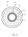
- FIG. 1 shows a case of lifted off from the O-ring 31 second valve body 18 flow connection 40 from the container interior to the container outer side between the inner edge of the collar edge 32 and the lower inner lid portion and between the second sealing seat 28 and O-ring 31st FIG.
- FIG. 2 also shows the position of the O-ring 31 in the annular groove 30 with closed vent path 40, ie in a position in which the second valve body 18 rests with its second sealing seat 28 on the O-ring 31 in the inner lid part 14 under the action of the closing compression spring 22 ,
- the flow connection and the vent path 40 pressure-tight sealing closed position of the O-ring 31 is compressed by the arrangement of the ventilation pockets 35 and in the region of these ventilation pockets bulging radially undulating.
- the first valve body 17 sits on the second valve body 18 (corresponding to FIG. 1 ) and the second valve body 18 other than in FIG. 1 represented on the inner cover part 14 and on the O-ring. 31. If a first limit value of the container internal pressure is exceeded, the first valve body 17 is raised against its closing pressure spring 22, since a connection between the container interior and the underside of the first valve body 17 past the tightly closing third valve body 19 and passes through the second valve body 18 therethrough. By opening a first flow connection, air can flow outward from the air cushion located above the liquid cooling medium, thereby compensating or reducing the overpressure.
- the second valve body 18 remains sealingly pressed against the collar edge 32 of the inner lid part 14. If the so-called overpressure degrades again below the first limit value, the first valve body 17 again comes into sealing contact with the second valve body 18. If, however, the container internal pressure continues to increase during or after the escape of the air cushion, this leads to the liquid cooling medium the underside of the second and third valve body 18 and 19 passes, in the manner described in the above-mentioned prior art results in a back pressure, which leads to an axial movement of the third valve body 19 against its third compression spring 43; By this sealing movement of the third valve body 19, the first-mentioned flow connection is closed.
- a reduction of the pressure leads to a return movement of the third valve body 19 and opening this connection path after the first-mentioned flow connection is closed again. If, on the other hand, the internal pressure of the container continues to increase, the second valve body 18 is lifted off the O-ring 31 of the inner lid part 14 against the first closing pressure spring 22 loaded on the first valve body 17, so that the so-called second flow connection 40 is opened and the said one very high pressure can be reduced (cf. FIG. 1 ).
- FIG. 1 Further, a negative pressure valve body 57 within the first pressure relief valve body 17 shows.
- vent pockets can also be smaller or larger, and that the ventilation pockets can also be arranged in an irregular arrangement along the circumference of the annular groove. Furthermore, it is possible to provide the ventilation pockets instead of the larger diameter inner circumference of the annular groove on the smaller diameter circumference of the annular groove radially inward.
- the vent pockets are formed by tapered or stepped shaped slots.
Landscapes
- Engineering & Computer Science (AREA)
- Chemical & Material Sciences (AREA)
- Combustion & Propulsion (AREA)
- Mechanical Engineering (AREA)
- General Engineering & Computer Science (AREA)
- Closures For Containers (AREA)
- Glass Compositions (AREA)
- Contacts (AREA)
- Magnetic Resonance Imaging Apparatus (AREA)
Claims (5)
- Bouchon de fermeture (11) pour des orifices ménagés sur des réservoirs, en particulier sur des radiateurs de véhicule automobile, comportant une partie intérieure (14), qui est maintenue sur une partie extérieure et dans laquelle est maintenu un système de valve (15) destiné à ouvrir et à fermer une liaison fluidique (40) entre l'intérieur du réservoir et l'extérieur du réservoir, le système de valve (15) comportant un corps de valve (18) mobile en va-et-vient, qui est poussé par précontrainte de manière élastique contre un siège d'étanchéité sur la partie intérieure (14) du bouchon et qui, lorsque la pression intérieure du réservoir est supérieure à une valeur limite déterminée, peut être détaché du siège d'étanchéité, caractérisé en ce que le siège d'étanchéité est formé sur la partie intérieure (14) du bouchon par un joint torique (31) maintenu dans une rainure annulaire (30) ouverte dans le sens axial, et en ce que la rainure annulaire (30) est élargie dans le sens radial par des poches d'aération (35) prévues sur un bord périphérique.
- Bouchon de fermeture selon la revendication 1, caractérisé en ce que les poches d'aération (35) sont situées dans le prolongement radial du bord périphérique extérieur de la rainure annulaire (30).
- Bouchon de fermeture selon la revendication 1 ou 2, caractérisé en ce que les poches d'aération (35) s'étendent sur toute la profondeur de la rainure annulaire (30).
- Bouchon de fermeture selon au moins l'une quelconque des revendications 1 à 3, caractérisé en ce que les poches d'aération (35) sont réparties uniformément sur le périmètre de la rainure annulaire (30).
- Bouchon de fermeture selon au moins l'une quelconque des revendications précédentes, caractérisé en ce que les poches d'aération (35) sont formées par d'étroites fentes (36) radiales.
Applications Claiming Priority (3)
| Application Number | Priority Date | Filing Date | Title |
|---|---|---|---|
| DE20211232U | 2002-07-18 | ||
| DE20211232U DE20211232U1 (de) | 2002-07-18 | 2002-07-18 | Verschlussdeckel |
| PCT/EP2003/005097 WO2004009973A1 (fr) | 2002-07-18 | 2003-05-15 | Bouchon de fermeture |
Publications (2)
| Publication Number | Publication Date |
|---|---|
| EP1523613A1 EP1523613A1 (fr) | 2005-04-20 |
| EP1523613B1 true EP1523613B1 (fr) | 2008-12-10 |
Family
ID=29594707
Family Applications (1)
| Application Number | Title | Priority Date | Filing Date |
|---|---|---|---|
| EP03730044A Expired - Lifetime EP1523613B1 (fr) | 2002-07-18 | 2003-05-15 | Bouchon de fermeture |
Country Status (5)
| Country | Link |
|---|---|
| US (1) | US20060151498A1 (fr) |
| EP (1) | EP1523613B1 (fr) |
| AT (1) | ATE417192T1 (fr) |
| DE (2) | DE20211232U1 (fr) |
| WO (1) | WO2004009973A1 (fr) |
Families Citing this family (2)
| Publication number | Priority date | Publication date | Assignee | Title |
|---|---|---|---|---|
| KR102484851B1 (ko) * | 2016-12-13 | 2023-01-05 | 현대자동차주식회사 | 차량의 냉각시스템용 압력캡 |
| DE102020107420A1 (de) | 2020-03-18 | 2021-09-23 | Grohe Ag | Vorrichtung mit einer durch einen Deckel verschließbaren Öffnung |
Family Cites Families (41)
| Publication number | Priority date | Publication date | Assignee | Title |
|---|---|---|---|---|
| DE3008002A1 (de) * | 1980-03-01 | 1981-09-10 | Reutter GmbH Metallwarenfabrik, 7050 Waiblingen | Verschlussdeckel insbesondere fuer einen kraftfahrzeugkuehler |
| DE3146824C2 (de) * | 1981-11-26 | 1999-09-02 | Reutter Metallwaren | "Verschlußdeckel, insbesondere für einen Kraftstofftank" |
| DE3150231A1 (de) * | 1981-12-18 | 1983-06-30 | Reutter Metallwarenfabrik GmbH, 7050 Waiblingen | Verschlussdeckel, insbesondere fuer einen kuehlerstutzen eines kraftfahrzeugs |
| FR2646405B1 (fr) * | 1989-04-28 | 1993-02-12 | Bailly Comte Ets | Bouchon de securite pour circuit sous pression |
| DE9002439U1 (fr) * | 1990-03-02 | 1990-05-03 | Sueddeutsche Kuehlerfabrik Julius Fr. Behr Gmbh & Co Kg, 7000 Stuttgart, De | |
| JP2555789B2 (ja) * | 1991-03-26 | 1996-11-20 | 豊田合成株式会社 | フユーエルキヤツプ |
| DE69209285T2 (de) * | 1992-08-07 | 1996-08-01 | Cherng Bing Jye | Angetriebener Kraftstofftankdeckel für Kraftfahrzeuge |
| JP3543833B2 (ja) * | 1993-12-24 | 2004-07-21 | 株式会社アステア | 給油口キャップ |
| ES2121626T3 (es) * | 1994-06-01 | 1998-12-01 | Heinrich Reutter | Tapa de cierre fijable a un manguito de deposito. |
| US5791507A (en) * | 1995-12-04 | 1998-08-11 | Stant Manufacturing Inc. | Quick-on cap with two-part closure body |
| WO1997048616A1 (fr) * | 1996-06-19 | 1997-12-24 | Heinrich Reutter | Couvercle pouvant etre fixe sur la tubulure d'un reservoir |
| DE29611514U1 (de) * | 1996-07-02 | 1997-10-30 | Reutter Heinrich | Verschlußdeckel mit temperaturabhängiger Abschraubsicherung |
| EP0970005A4 (fr) * | 1997-02-11 | 2000-08-02 | Stant Mfg Co | Joint pour ensemble fermeture/goulot de remplissage |
| CA2288078A1 (fr) * | 1997-04-21 | 1998-10-29 | Stant Manufacturing Inc. | Bouchon verrouillable pour reservoir a carburant |
| CA2297142C (fr) * | 1997-07-23 | 2004-01-13 | Stant Manufacturing Inc. | Bouchon de reservoir |
| DE19753597A1 (de) * | 1997-12-03 | 1999-06-24 | Heinrich Reutter | Verschlußdeckel für Kraftfahrzeugkühler |
| DE19753592A1 (de) * | 1997-12-03 | 1999-06-10 | Heinrich Reutter | Verschlußdeckel |
| US6213331B1 (en) * | 1998-02-09 | 2001-04-10 | Shaw Aero Development, Inc. | Fuel cap having biased seal |
| US6705481B2 (en) * | 1998-03-20 | 2004-03-16 | Temtec Fahrzeutechnick | Actuatable fuel tank closure having guide pipe |
| DE69929348T2 (de) * | 1998-10-06 | 2006-07-27 | Stant Manufacturing Inc., Connersville | Verschlusskappe |
| WO2000029239A1 (fr) * | 1998-11-18 | 2000-05-25 | Heinrich Reutter | Bouchon pour le reservoir a carburant d'un vehicule automobile |
| US6230918B1 (en) * | 1999-01-21 | 2001-05-15 | Stant Manufacturing Inc. | Quick-on filler neck cap |
| DE19923774A1 (de) * | 1999-05-22 | 2000-11-23 | Heinrich Reutter | Verschlußdeckel für Kraftfahrzeugkühler |
| DE19923775A1 (de) * | 1999-05-22 | 2000-11-23 | Heinrich Reutter | Verschlußdeckel für Kraftfahrzeugkühler |
| WO2001017872A1 (fr) * | 1999-09-10 | 2001-03-15 | Stant Manufacturing Inc. | Bouchon de reservoir a carburant muni d'un ressort d'ejection du bouchon |
| DE10012184A1 (de) * | 2000-03-13 | 2001-09-20 | Heinrich Reutter | Verschlussdeckel |
| US20030150859A1 (en) * | 2000-03-14 | 2003-08-14 | Heinrich Reutter | Sealing cap |
| DE10034761A1 (de) * | 2000-03-31 | 2002-01-31 | Heinrich Reutter | Verschlussdeckel |
| DE10035729A1 (de) * | 2000-07-22 | 2002-01-31 | Heinrich Reutter | Verschlussdeckel mit Verdrehsicherung |
| DE20012722U1 (de) * | 2000-07-22 | 2001-12-13 | Reutter Heinrich | Verschlussdeckel für Kraftfahrzeugkühler |
| DE60116391T2 (de) * | 2000-09-18 | 2006-07-27 | Stant Manufacturing Inc., Connersville | Drehmomentgrenzwertsignalverschlusskappe für einen einfüllstutzen |
| DE20107582U1 (de) * | 2001-05-04 | 2002-09-12 | Reutter Heinrich | Behälterverschluß und Verschlußdeckel eines derartigen Behälterverschlusses |
| DE20108735U1 (de) * | 2001-05-23 | 2002-10-02 | Reutter Heinrich | Verschlussdeckel für Kraftfahrzeugkühler |
| DE10132661A1 (de) * | 2001-07-05 | 2003-01-16 | Heinrich Reutter | Verschlussdeckel mit Abschraubsicherung |
| US6648160B2 (en) * | 2001-07-17 | 2003-11-18 | Matthew Jon Hotch | Flush fuel cap |
| DE20120676U1 (de) * | 2001-12-21 | 2003-04-30 | Reutter Heinrich | Verschlußdeckel für Kraftfahrzeugkühler |
| DE10164669A1 (de) * | 2001-12-22 | 2003-07-03 | Reutter Heinrich | Abschraubsicherungsvorrichtung für Behälter |
| DE10164676A1 (de) * | 2001-12-22 | 2003-07-03 | Heinrich Reutter | Verschlussdeckel für Kraftfahrzeugkühler |
| DE20201082U1 (de) * | 2002-01-24 | 2003-06-05 | Reutter Heinrich | Verschlussdeckel für Kraftfahrzeugkühler |
| JP2004035016A (ja) * | 2002-07-01 | 2004-02-05 | Nifco Inc | 燃料タンク用キャップ装置 |
| JP4219229B2 (ja) * | 2003-07-18 | 2009-02-04 | 株式会社アステア | 給油口キャップ |
-
2002
- 2002-07-18 DE DE20211232U patent/DE20211232U1/de not_active Expired - Lifetime
-
2003
- 2003-05-15 US US10/521,458 patent/US20060151498A1/en not_active Abandoned
- 2003-05-15 WO PCT/EP2003/005097 patent/WO2004009973A1/fr not_active Application Discontinuation
- 2003-05-15 DE DE50310902T patent/DE50310902D1/de not_active Expired - Fee Related
- 2003-05-15 AT AT03730044T patent/ATE417192T1/de not_active IP Right Cessation
- 2003-05-15 EP EP03730044A patent/EP1523613B1/fr not_active Expired - Lifetime
Also Published As
| Publication number | Publication date |
|---|---|
| ATE417192T1 (de) | 2008-12-15 |
| US20060151498A1 (en) | 2006-07-13 |
| EP1523613A1 (fr) | 2005-04-20 |
| DE50310902D1 (de) | 2009-01-22 |
| WO2004009973A8 (fr) | 2005-03-31 |
| DE20211232U1 (de) | 2003-11-20 |
| WO2004009973A1 (fr) | 2004-01-29 |
Similar Documents
| Publication | Publication Date | Title |
|---|---|---|
| EP3576825B1 (fr) | Dispositif de distribution pour un milieu fluide | |
| DE2724529C2 (fr) | ||
| DE1073816B (de) | Abgabeventil für Behälter, die mit einer Flüssigkeit und einem Druckgas gefüllt sind | |
| EP1303687B1 (fr) | Bouchon de fermeture a systeme de blocage en rotation | |
| EP1268993B1 (fr) | Bouchon de fermeture | |
| DE2912977A1 (de) | Entlueftungsventil | |
| DE1297936B (de) | Kuehlerverschlusskappe | |
| DE102009006428B4 (de) | Austragvorrichtung | |
| EP1523613B1 (fr) | Bouchon de fermeture | |
| EP1402157B1 (fr) | Bouchon de fermeture protection contre le devissage | |
| EP1264087B1 (fr) | Couvercle de fermeture | |
| WO2002090202A1 (fr) | Fermeture de contenant et bouchon de fermeture d'une telle fermeture de contenant | |
| EP1036261B1 (fr) | Couvercle de fermeture | |
| DE60027304T2 (de) | Sicherheitsdichtung des schliesselements einer fülltüte für grossbehälter | |
| DE19850382B4 (de) | Vorrichtung zum Ablaß des in einem Bauteil eines Kraftfahrzeuges enthaltenen Öls | |
| DE20316580U1 (de) | Verschlussdeckel für Kraftfahrzeugkühler | |
| DE19732885B4 (de) | Verschlussdeckel mit Sicherheitsverriegelung für einen Behälter | |
| DE102007061753A1 (de) | Nachfüllbehälter für einen Tank | |
| DE102017103133B4 (de) | Verschluss für einen Behälter zur Aufnahme und Abgabe von Flüssigkeiten | |
| EP3815792B1 (fr) | Pompe à mousse | |
| DE10012184A1 (de) | Verschlussdeckel | |
| DE3803166A1 (de) | Ueberdruckventileinrichtung fuer den kuehlkreislauf einer fluessigkeitsgekuehlten brennkraftmaschine | |
| DE10015563A1 (de) | Verschlussdeckel | |
| WO1999057032A1 (fr) | Bouchon filete pour bouteilles | |
| DE7721665U1 (de) | Kraftstoffmembranpumpe mit absperrventil |
Legal Events
| Date | Code | Title | Description |
|---|---|---|---|
| PUAI | Public reference made under article 153(3) epc to a published international application that has entered the european phase |
Free format text: ORIGINAL CODE: 0009012 |
|
| 17P | Request for examination filed |
Effective date: 20041222 |
|
| AK | Designated contracting states |
Kind code of ref document: A1 Designated state(s): AT BE BG CH CY CZ DE DK EE ES FI FR GB GR HU IE IT LI LU MC NL PT RO SE SI SK TR |
|
| GRAP | Despatch of communication of intention to grant a patent |
Free format text: ORIGINAL CODE: EPIDOSNIGR1 |
|
| GRAS | Grant fee paid |
Free format text: ORIGINAL CODE: EPIDOSNIGR3 |
|
| GRAS | Grant fee paid |
Free format text: ORIGINAL CODE: EPIDOSNIGR3 |
|
| GRAA | (expected) grant |
Free format text: ORIGINAL CODE: 0009210 |
|
| AK | Designated contracting states |
Kind code of ref document: B1 Designated state(s): AT BE BG CH CY CZ DE DK EE ES FI FR GB GR HU IE IT LI LU MC NL PT RO SE SI SK TR |
|
| REG | Reference to a national code |
Ref country code: GB Ref legal event code: FG4D Free format text: NOT ENGLISH |
|
| REG | Reference to a national code |
Ref country code: CH Ref legal event code: EP |
|
| REG | Reference to a national code |
Ref country code: IE Ref legal event code: FG4D Free format text: LANGUAGE OF EP DOCUMENT: GERMAN |
|
| REF | Corresponds to: |
Ref document number: 50310902 Country of ref document: DE Date of ref document: 20090122 Kind code of ref document: P |
|
| PG25 | Lapsed in a contracting state [announced via postgrant information from national office to epo] |
Ref country code: FI Free format text: LAPSE BECAUSE OF FAILURE TO SUBMIT A TRANSLATION OF THE DESCRIPTION OR TO PAY THE FEE WITHIN THE PRESCRIBED TIME-LIMIT Effective date: 20081210 Ref country code: NL Free format text: LAPSE BECAUSE OF FAILURE TO SUBMIT A TRANSLATION OF THE DESCRIPTION OR TO PAY THE FEE WITHIN THE PRESCRIBED TIME-LIMIT Effective date: 20081210 Ref country code: SI Free format text: LAPSE BECAUSE OF FAILURE TO SUBMIT A TRANSLATION OF THE DESCRIPTION OR TO PAY THE FEE WITHIN THE PRESCRIBED TIME-LIMIT Effective date: 20081210 |
|
| NLV1 | Nl: lapsed or annulled due to failure to fulfill the requirements of art. 29p and 29m of the patents act | ||
| REG | Reference to a national code |
Ref country code: IE Ref legal event code: FD4D |
|
| PG25 | Lapsed in a contracting state [announced via postgrant information from national office to epo] |
Ref country code: BG Free format text: LAPSE BECAUSE OF FAILURE TO SUBMIT A TRANSLATION OF THE DESCRIPTION OR TO PAY THE FEE WITHIN THE PRESCRIBED TIME-LIMIT Effective date: 20090310 Ref country code: EE Free format text: LAPSE BECAUSE OF FAILURE TO SUBMIT A TRANSLATION OF THE DESCRIPTION OR TO PAY THE FEE WITHIN THE PRESCRIBED TIME-LIMIT Effective date: 20081210 Ref country code: ES Free format text: LAPSE BECAUSE OF FAILURE TO SUBMIT A TRANSLATION OF THE DESCRIPTION OR TO PAY THE FEE WITHIN THE PRESCRIBED TIME-LIMIT Effective date: 20090321 Ref country code: IE Free format text: LAPSE BECAUSE OF FAILURE TO SUBMIT A TRANSLATION OF THE DESCRIPTION OR TO PAY THE FEE WITHIN THE PRESCRIBED TIME-LIMIT Effective date: 20081210 Ref country code: RO Free format text: LAPSE BECAUSE OF FAILURE TO SUBMIT A TRANSLATION OF THE DESCRIPTION OR TO PAY THE FEE WITHIN THE PRESCRIBED TIME-LIMIT Effective date: 20081210 |
|
| PG25 | Lapsed in a contracting state [announced via postgrant information from national office to epo] |
Ref country code: SE Free format text: LAPSE BECAUSE OF FAILURE TO SUBMIT A TRANSLATION OF THE DESCRIPTION OR TO PAY THE FEE WITHIN THE PRESCRIBED TIME-LIMIT Effective date: 20090310 Ref country code: PT Free format text: LAPSE BECAUSE OF FAILURE TO SUBMIT A TRANSLATION OF THE DESCRIPTION OR TO PAY THE FEE WITHIN THE PRESCRIBED TIME-LIMIT Effective date: 20090511 Ref country code: CZ Free format text: LAPSE BECAUSE OF FAILURE TO SUBMIT A TRANSLATION OF THE DESCRIPTION OR TO PAY THE FEE WITHIN THE PRESCRIBED TIME-LIMIT Effective date: 20081210 |
|
| PG25 | Lapsed in a contracting state [announced via postgrant information from national office to epo] |
Ref country code: SK Free format text: LAPSE BECAUSE OF FAILURE TO SUBMIT A TRANSLATION OF THE DESCRIPTION OR TO PAY THE FEE WITHIN THE PRESCRIBED TIME-LIMIT Effective date: 20081210 |
|
| PLBE | No opposition filed within time limit |
Free format text: ORIGINAL CODE: 0009261 |
|
| STAA | Information on the status of an ep patent application or granted ep patent |
Free format text: STATUS: NO OPPOSITION FILED WITHIN TIME LIMIT |
|
| PG25 | Lapsed in a contracting state [announced via postgrant information from national office to epo] |
Ref country code: DK Free format text: LAPSE BECAUSE OF FAILURE TO SUBMIT A TRANSLATION OF THE DESCRIPTION OR TO PAY THE FEE WITHIN THE PRESCRIBED TIME-LIMIT Effective date: 20081210 |
|
| 26N | No opposition filed |
Effective date: 20090911 |
|
| BERE | Be: lapsed |
Owner name: REUTTER, HEINRICH Effective date: 20090531 |
|
| PG25 | Lapsed in a contracting state [announced via postgrant information from national office to epo] |
Ref country code: MC Free format text: LAPSE BECAUSE OF NON-PAYMENT OF DUE FEES Effective date: 20090531 |
|
| REG | Reference to a national code |
Ref country code: CH Ref legal event code: PL |
|
| GBPC | Gb: european patent ceased through non-payment of renewal fee |
Effective date: 20090515 |
|
| PG25 | Lapsed in a contracting state [announced via postgrant information from national office to epo] |
Ref country code: CH Free format text: LAPSE BECAUSE OF NON-PAYMENT OF DUE FEES Effective date: 20090531 Ref country code: LI Free format text: LAPSE BECAUSE OF NON-PAYMENT OF DUE FEES Effective date: 20090531 |
|
| REG | Reference to a national code |
Ref country code: FR Ref legal event code: ST Effective date: 20100129 |
|
| PG25 | Lapsed in a contracting state [announced via postgrant information from national office to epo] |
Ref country code: FR Free format text: LAPSE BECAUSE OF NON-PAYMENT OF DUE FEES Effective date: 20090602 |
|
| PG25 | Lapsed in a contracting state [announced via postgrant information from national office to epo] |
Ref country code: GB Free format text: LAPSE BECAUSE OF NON-PAYMENT OF DUE FEES Effective date: 20090515 |
|
| PG25 | Lapsed in a contracting state [announced via postgrant information from national office to epo] |
Ref country code: BE Free format text: LAPSE BECAUSE OF NON-PAYMENT OF DUE FEES Effective date: 20090531 Ref country code: DE Free format text: LAPSE BECAUSE OF NON-PAYMENT OF DUE FEES Effective date: 20091201 |
|
| PG25 | Lapsed in a contracting state [announced via postgrant information from national office to epo] |
Ref country code: AT Free format text: LAPSE BECAUSE OF NON-PAYMENT OF DUE FEES Effective date: 20090515 |
|
| PG25 | Lapsed in a contracting state [announced via postgrant information from national office to epo] |
Ref country code: GR Free format text: LAPSE BECAUSE OF FAILURE TO SUBMIT A TRANSLATION OF THE DESCRIPTION OR TO PAY THE FEE WITHIN THE PRESCRIBED TIME-LIMIT Effective date: 20090311 |
|
| PG25 | Lapsed in a contracting state [announced via postgrant information from national office to epo] |
Ref country code: IT Free format text: LAPSE BECAUSE OF FAILURE TO SUBMIT A TRANSLATION OF THE DESCRIPTION OR TO PAY THE FEE WITHIN THE PRESCRIBED TIME-LIMIT Effective date: 20081210 |
|
| PG25 | Lapsed in a contracting state [announced via postgrant information from national office to epo] |
Ref country code: LU Free format text: LAPSE BECAUSE OF NON-PAYMENT OF DUE FEES Effective date: 20090515 |
|
| PG25 | Lapsed in a contracting state [announced via postgrant information from national office to epo] |
Ref country code: HU Free format text: LAPSE BECAUSE OF FAILURE TO SUBMIT A TRANSLATION OF THE DESCRIPTION OR TO PAY THE FEE WITHIN THE PRESCRIBED TIME-LIMIT Effective date: 20090611 |
|
| PG25 | Lapsed in a contracting state [announced via postgrant information from national office to epo] |
Ref country code: TR Free format text: LAPSE BECAUSE OF FAILURE TO SUBMIT A TRANSLATION OF THE DESCRIPTION OR TO PAY THE FEE WITHIN THE PRESCRIBED TIME-LIMIT Effective date: 20081210 |
|
| PG25 | Lapsed in a contracting state [announced via postgrant information from national office to epo] |
Ref country code: CY Free format text: LAPSE BECAUSE OF FAILURE TO SUBMIT A TRANSLATION OF THE DESCRIPTION OR TO PAY THE FEE WITHIN THE PRESCRIBED TIME-LIMIT Effective date: 20081210 |