EP1522952B1 - Digitalkamera - Google Patents
Digitalkamera Download PDFInfo
- Publication number
- EP1522952B1 EP1522952B1 EP04256236.3A EP04256236A EP1522952B1 EP 1522952 B1 EP1522952 B1 EP 1522952B1 EP 04256236 A EP04256236 A EP 04256236A EP 1522952 B1 EP1522952 B1 EP 1522952B1
- Authority
- EP
- European Patent Office
- Prior art keywords
- image data
- subject
- digital camera
- computation
- image
- Prior art date
- Legal status (The legal status is an assumption and is not a legal conclusion. Google has not performed a legal analysis and makes no representation as to the accuracy of the status listed.)
- Expired - Lifetime
Links
Images


Classifications
-
- H—ELECTRICITY
- H04—ELECTRIC COMMUNICATION TECHNIQUE
- H04N—PICTORIAL COMMUNICATION, e.g. TELEVISION
- H04N1/00—Scanning, transmission or reproduction of documents or the like, e.g. facsimile transmission; Details thereof
- H04N1/32—Circuits or arrangements for control or supervision between transmitter and receiver or between image input and image output device, e.g. between a still-image camera and its memory or between a still-image camera and a printer device
- H04N1/32101—Display, printing, storage or transmission of additional information, e.g. ID code, date and time or title
- H04N1/32106—Display, printing, storage or transmission of additional information, e.g. ID code, date and time or title separate from the image data, e.g. in a different computer file
- H04N1/32122—Display, printing, storage or transmission of additional information, e.g. ID code, date and time or title separate from the image data, e.g. in a different computer file in a separate device, e.g. in a memory or on a display separate from image data
-
- G—PHYSICS
- G06—COMPUTING OR CALCULATING; COUNTING
- G06V—IMAGE OR VIDEO RECOGNITION OR UNDERSTANDING
- G06V40/00—Recognition of biometric, human-related or animal-related patterns in image or video data
- G06V40/10—Human or animal bodies, e.g. vehicle occupants or pedestrians; Body parts, e.g. hands
- G06V40/16—Human faces, e.g. facial parts, sketches or expressions
- G06V40/161—Detection; Localisation; Normalisation
- G06V40/166—Detection; Localisation; Normalisation using acquisition arrangements
-
- H—ELECTRICITY
- H04—ELECTRIC COMMUNICATION TECHNIQUE
- H04N—PICTORIAL COMMUNICATION, e.g. TELEVISION
- H04N23/00—Cameras or camera modules comprising electronic image sensors; Control thereof
- H04N23/60—Control of cameras or camera modules
- H04N23/61—Control of cameras or camera modules based on recognised objects
- H04N23/611—Control of cameras or camera modules based on recognised objects where the recognised objects include parts of the human body
-
- H—ELECTRICITY
- H04—ELECTRIC COMMUNICATION TECHNIQUE
- H04N—PICTORIAL COMMUNICATION, e.g. TELEVISION
- H04N23/00—Cameras or camera modules comprising electronic image sensors; Control thereof
- H04N23/60—Control of cameras or camera modules
- H04N23/67—Focus control based on electronic image sensor signals
- H04N23/673—Focus control based on electronic image sensor signals based on contrast or high frequency components of image signals, e.g. hill climbing method
Definitions
- the present invention relates to a digital camera that identifies a feature of a person and implements a focus and exposure actions responsive to a result of the identification.
- Japanese Laid-Open Patent Application H9-251534 has described in detail an identification method in which an eye, nose and mouth etc are extracted and registered as a feature and then, identity is identified by comparing the registered feature with a feature extracted from input image data and Japanese Laid-Open Patent Application H10-232934 has disclosed a way to improve an accuracy of an image database dictionary when registering such the extracted feature.
- Japanese Laid-Open Patent Application 2001-201779 has disclosed that a camera user was registered as reference information and a camera action becomes enabled only when input identification information meets the registered reference information by photographing the camera user with a camera pointing at its face.
- Japanese Laid-Open Patent Application 2001-309225 has disclosed a camera in which data such as a face coordinate, face dimension, an eye position, a pause of a head and the like recognized in accordance with a face recognition algorithm is stored in an image memory along with image data.
- Japanese Laid-Open Patent Application 2001-326841 has also disclosed an imaging device (digital camera) that stores identification information (face, fingerprint and palm print) to identify an authentic user beforehand.
- Japanese Laid-Open Patent Application 2002-232761 has also disclosed an image storage device that stores a photographed image by linking the photographed image to previously read identification information about a subject.
- Japanese Laid-Open Patent Application 2002-333652 has disclosed an imaging device that generates a storage signal by comparing previously stored profile information with photographed face information. This profile information is stored in a priority order.
- EP 1 429 290 A relates to an image correction apparatus and an image pickup apparatus for detecting a particular eye-related defect, such as red-eyes and gold-eyes, in an image and correcting the detected defect, the number of positions in an image at which a particularly eye-related defect, such as red-eye portion and a gold-eye portion, has been detected is displayed together with an image including the positions.
- a particular eye-related defect such as red-eyes and gold-eyes
- Patent Application JP 2002-27314 relates to an imaging device including a solid state image pickup element for photoelectrically converting an optical image to output image data, an operating unit for designating to input an image size and store the image, and control means for controlling the image pickup element.
- the control means judges whether the image size is input by the operating unit, and reads the image data from an overall effective imaging region of the pickup element when not put in, and subsequently reads the image data from a region corresponding to the image size of the effective region of the image pickup means when put in.
- a present invention is aimed at providing a digital camera having an easy-of-use subject identification function close to a conventional action sequence that has not been attained in a camera with a conventional subject identification function.
- the invention provides a digital camera according to claim 1. Namely, image data output from an imaging device for the image display is once stored in the second storage device and the feature section is extracted from the stored image data, so the extraction is not affected by an update of the first storage device.
- image data stored in the first storage device stores only image data of the small number of pixels responsive to the number of pixels of the display device, so processing on this image data can be quickly implemented.
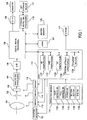
- FIG. 1 is a functional block view explaining a major function about a digital camera of an embodiment of this invention.
- Image-taking lens 101 includes a zoom lens that changes its focus distance continuously and a focus lens that adjusts a focus point. These lenses are driven by driver 113.
- driver 113 has a zoom drive unit and its drive circuit for the zoom lens and a focus drive unit and its drive circuit for the focus lens and these units and circuits are controlled by CPU 112.
- Image-taking lens 101 forms a subject image on an image-forming surface of imaging element 103.
- Imaging element 103 is a photoelectric element that outputs an electric signal responsive to a light intensity of the subject image formed on the image-forming surface and a CCD pr MOS-type solid state imaging element is used. Imaging element 103 is driven by driver 115 that controls timing of extracting a signal. Diaphragm 102 is arranged between image-taking lens 1021 and imaging element 103. Diaphragm 102 is driven by driver 114 that includes an aperture unit and its drive circuit. An imaging signal from solid imaging element 103 is input into analogue signal processing circuit 104 and then correlation double sampling (CDS) and the like is processed on the imaging signal by analogue signal processing circuit 104. The imaging signal processed by analogue signal processing circuit 104 is converted into a digital signal from an analogue signal by A/D converter 135.
- CDS correlation double sampling
- Buffer memory 105 is a frame memory capable of storing data for a plurality of frames imaged by imaging element 103 and the A/D converted signal is temporally stored in buffer memory 105.
- Digital signal processing circuit 106 implements the image processing by importing the data stored in buffer memory 105 and the post-processed data is stored again in buffer memory 105.
- CPU 112 is connected to digital signal processing circuit 106 and drivers 113 through 115 and executes a sequence control when a camera is operated.
- AE computation section 1121 of CPU 112 computes an exposure based upon an image signal from the imaging element and AWB computation section 1122 thereof computes to determine a parameter for a white balance.
- Feature-extraction-computation section 1123 of CPU 112 stores features like a shape, position, size etc of a subject from image data in accordance with a predetermined algorithm in storage section 1125 thereof and computes an extracted size such as a face, a width between eyes etc and rough distances to respective subjects extracted from focus distances of the zoom lens detected by detection device 121 and then stores the computed size and distances in storage section 1125 thereof with a day and time of the extraction.
- a way of computing this distance will be described using Fig.7. Fig.
- A is an average value of real widths between eyes of a general adult, a an extracted width between eyes formed on the imaging element, L a distance from an image-taking lens to a subject person and f a focal length. From this figure, a following proportional expression can readily be obtained.
- An AF system in a digital camera of the embodiment of this invention employs a contrast method.
- a contrast method There is a correlation between a degree of an out-of-focus image on imaging element 103 and its contrast and thereby a focus is adjusted by using that an image contrast becomes a maximum when the image comes into focus.
- a size of the contrast can be evaluated by a size of a high frequency component of an imaging signal.
- AF computation section 1124 extracts a high frequency component of an imaging signal and as a focus evaluation value that is a value which integrates an absolute value of the high frequency component, an AF computation is implemented based upon the focus evaluation value.
- CPU 112 causes a focus lens position of image-taking lens 101 to be adjusted and a focus action to be taken, using a computation result of AF computation section 1124.
- power switch 1161 that turns a camera power on and off
- half-depressing switch 1162 and full-depressing switch 1163 that turn on and off coupling with a release button
- setting button 1164 that selects various menus to be used and be displayed on monitor display 109 at a time of a picture taking and up/down (U/D) button 1165 that updates a reproduction image etc and the like.
- Setting button 1164 also enables to select and set various characters to name the extracted features by using U/D button 1165.
- U/D button 1165 is used to select a desired person from a plurality of extracted persons and drive the zoom lens manually toward a telephoto lens side or a wide-angle side when shooting.
- this flash When subject brightness is low, flash 117 is fired.
- this flash includes a pre-flash function that prevents a pupil of a person from being photographed in red when firing a flash or lessens a so-called red eye phenomenon when so fired and fires a supplementary flash beforehand prior to a shooting to measure subject brightness in advance at dim brightness.
- a peak value of an evaluation value detected from an AE computation result and a corresponding lens position and the like are stored in storage section 1125.
- the image data variously processed by digital signal processing circuit 106 is stored in external storage medium 111 like a memory card etc via record & reproduction signal processing circuit 110 after being temporally stored in buffer memory 105.
- Record & reproduction signal processing circuit 110 implements a data compression for storing image data in external storage medium 111 and a decompression process of the compressed image data reproduced from external storage medium 111.
- Monitor display 109 is a liquid crystal display device (LCD) to display a photographed subject image and various setting menus when shooting or playing back. Herein, this monitor display is also used when playing back and displaying image data stored in storage medium 111.
- image data stored in VRAM 107 that is a part of buffer memory 105 is extracted and digital image data is converted to an analogue picture image signal by D/A converter 108. Then, the image is displayed on monitor display 109 by using this analogue picture image signal.
- buffer memory 105 When image data for displaying is played back on monitor display 109, data for displaying that is thinned out from image data for a still image is continuously produced at a certain cycle (e.g. 30 f/sec.) from the imaging element. Then, the image data is given a predetermined process, and data thereof is further thinned out such that the number of pixels of the image data makes the number of pixels responsive to vertical and horizontal pixels of monitor display 109 and then this thinned-out data is continuously stored in VRAM 107.
- the data of VRAM 107 is played back as a display image on monitor display 109 through D/A converter 108.
- This image data of VRAM 107 is also used as data to extract features.
- image data of VRAM 107 is stored again in buffer memory 105 at a predetermined timing.
- predetermined scope e.g. 80% vertically and horizontally
- Fig. 6 shows an example of this scope within a screen.
- an area indicated by a chain line inclusive of three persons within a display screen is a scope that is stored in buffer memory 105.
- features are extracted from only image data excluding the subject on the marginal section with feature-extraction computation section 1123 from the beginning.
- a camera is set to an extraction mode for an extraction operation using setting button 1164 as described before, it is preferable that displaying of such the extractable scope can remind a user of the extraction mode.
- image data is stored again in buffer memory 105 from VRAM 107. If a processing power of CPU 112 were high, a feature extraction could be implemented at a rate of 30 f /sec., but the processing power of many CPUs employed in digital cameras on the market is not so high. Therefore, image data is stored again in buffer memory 105 from VRAM 107 at a rate matching a feature extraction computation corresponding to the processing power of CPU 112 and thereby the feature can be extracted. In this case, an image data for displaying is output at a normal rate from VRAM 107, so it is matter of course that a display and update rate do not get late.
- AE and AF computations use image data that is output from imaging element 103, but is not yet thinned out for being stored in VRAM 107.
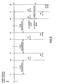
- Fig. 8 shows timing in a case where face recognition is possible from a camera operation start whereas Fig. 9 shows timing in the event that the face recognition is impossible.
- a horizontal axis is a time axis on a basis of a cycle (e.g. 30 f/sec.) extracted from imaging element 103 and herein the face recognition process is supposed to be complete within two cycles.
- AF and AE computations and AF and AWB computations are implemented respectively in series within one cycle.
- Fig. 8 when a camera is actuated, firstly an aperture is stopped down so as to be a minimum aperture and the focus lens is moved to a hyperfocal distance position responsive to the minimum aperture.
- the hyperfocal distance position is a position from the nearest shooting distance from which depth of field of image-taking lens 101 extends through infinity. When shooting at this position, the depth of field extends over everything from half the hyperfocal distance to infinity. A fine detail of contents about an initial setting will be described later.
- the face recognition computation is started from time t1 by using data exposed with imaging element 103 after the initial setting is finished.
- the AF and AE computations are implemented with respect to predetermined scope inclusive of a recognized face by using output data thinned out for a motion image from imaging element 103.
- the focus lens is driven based upon this AF computation result and once the lens is focused, a driving range of the focus lens is limited to a predetermined range in the vicinity of the focused position from then on. With this, even if a subject moves and goes out of an AF area, an abrupt focusing on a backdrop can be avoided.
- a primary subject to implement the AF computation varies with a change in a size and distance of each extracted subject and thereby there are cases where a frequent back-and-forth moving focus lens causes annoying.
- the AF computation may be implemented when the face recognition becomes impossible without a periodical AF computation.
- the AF computation in parentheses in Fig.8 shows a case where the AF computation is not implemented like the foregoing.
- the AE computation is implemented and then the AF and AWB computations are implemented by using an output from imaging element 103 at time t3 after completion of the AE computation.
- the AF computation is implemented as needed in the same way as with a previous cycle. From time t4, a face recognition computation is implemented and after this, the same cycle will be repeated from time 1.
- the reason why such the same action is repeated is that the focus lens is caused to move based upon a result of the AF computation implemented between time t2 and time t3 and image data exposed by imaging element 103 between time t4 and time 5 after movement completion is used for face recognition process.
- a shooting mode set on a camera at time t6 is checked. A detail of this shooting mode will be described later.
- the focus lens When a shooting mode with emphasis on a person is set, the focus lens is moved to the position of the hyperfocal distance as described before. Also, when a shooting mode with emphasis on scenery is set, the AF computation is implemented in the same way as the one at time t2 or time t4 and the focus lens is moved to a focus position based upon a result of the AF computation. In a cycle from time t7 when the AE computation is complete, the focus lens stays fixed at the position of the hyperfocal distance when the shooting mode with emphasis on a person is set, whereas, when the shooting mode with emphasis on scenery is set, a new AF computation is implemented.
- the face recognition computation is implemented at time t8 and process from time t5 will be repeated from then on.
- process from time t2 and then on as shown in Fig.8 will be repeated.
- process from time t2 and then on as shown in Fig.9 process from time t2 and then on as shown in Fig.9 .
- a cycle is started from time t2 in a case of the AWB computation, but the AWB computation may be implemented in a cycle at time t3 and time t5 after the AE computation is complete in the same way as in Fig.8 .
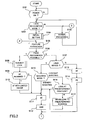
- Figs.2 through 5 are flow charts organizing the series of action sequences as described in Fig.9 .
- step S101 of Fig.2 when a power-on of a digital camera is detected by turning power switch SW1161 on, it is judged in step S102 whether or not an action mode of the digital camera is set to a face recognition mode.
- This face recognition mode can be set by way of, for example, setting button 1164 as well.
- the face recognition mode is set, the recognizable area indicated by the chain line as shown in Fig.6 is displayed on monitor display 109.
- step S103 AF, AE and AWB actions are implemented in accordance with a predetermined sequence to execute a normal shooting action.
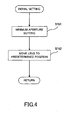
- step S104 an initial setting for a face recognition process is input. A specific example of this initial setting will be described later.
- step S105 features of a subject are extracted with feature extraction computation section 1123 by using an exposed image data after completion of the initial setting.
- step S106 CPU 112 judges whether or not a person's face is recognizable based upon the extracted features.
- a flow proceeds to step S107, but when the face recognition is possible, a flow proceeds to step S108.
- step S108 a subject lock is set to a primary subject that a photo shooter once sets. This locking is to permit the photo shooter to photograph readily from then on while following the subject. A setting of the subject lock will be described in detail referring to Fig.5 .
- step S109 it is judged whether or not the AF computation is required to be implemented the locked subject.
- the AF computation has been implemented prior to AF and AWB computations, but as described in Fig.8 , what the face recognition is made means that the focus lens stays at a focus position or near its focus position, so the AF computation is not always required prior to AE and AWB computations and thus it is sufficient such that the AF computation is configured to be implemented once every two or three times of the AE and AWB computations.
- the AF computation may be implemented assuming that a deviation from a focus point is large when the focus evaluation value as described before is below a predetermined value.
- step S111 if the AF computation is not required, a flow proceeds to step S111, but when the AF computation is required, a flow proceeds to step S110 where the AF computation is implemented by limiting a movement range of the focus lens. This is based upon a supposition that the primary subject does not move overly from a present position if the subject moves. With such the limitation of the movement range of the focus lens, when the primary subject moves and goes out of the AF area, the focus lens can be prevented from moving excessively to focus on a backdrop depending upon a result of the AF computation.
- step S111 After completion of the AF computation, then, the AE computation is implemented in step S111 and in step S112, the AWB (automatic white balance) computation is implemented and then a flow moves on to step S118 of Fig.8 .
- the AF computation may be implemented prior to the AWB computation of step S112.
- step S107 it is judged whether or not the focus lens is moved after the face recognition is judged to be impossible. Namely, it is judged whether or not the face recognition is judged to be impossible in step S106 subsequent to the focus lens movement.
- a flow proceeds to step S113 where the AF computation is implemented and then, the AE computation is implemented in step S114 and a flow moves on to step S118 of Fig.8 .
- a flow proceeds to step S115 where it is judged what a shooting mode is set to the digital camera.
- the shooting mode referred to herein is a shooting mode that places emphasis on a person like a portrait mode, a commemorative picture mode etc or a shooting mode that puts emphasis on scenery like a landscape mode, a night scene mode etc. It is judged what a mode is set. This mode is set via setting button 1164 while a user views a menu displayed on monitor display 109.
- step S116 When the shooting mode is set to a mode with emphasis on a person, a flow proceeds to step S116 and it goes to step S111 when it is set to the mode with emphasis on scenery.
- a latest position of the focus lens is checked in step S116 and a flow proceeds to step S111 when the lens stays at the hyperfocal distance and when the lens stays other than at the hyperfocal distance, a flow moves on to step S111 after the lens is moved to the position of the hyperfocal distance in step S116.
- the focus lens may be configured to be moved to a fixed position (e.g. shooting distance at 2m or so) not relying on an aperture value instead of the position of the hyperfocal distance.
- a flow may be configured to get back to step S105. Namely, it is presumed that one-time judgment is not sufficient since a subject happens to look aside.
- a flow gets back to step S105 and it is judged once again whether or not the recognition is possible, and a judgment may be configured such that the recognition is finally judged to be impossible when predetermined-times face recognitions are all impossible in a row. This enables an enhancement of an accuracy of the subject recognition.
- step S115 When the mode is judged to be set to the landscape shooting mode in step S115, a flow proceeds to step S111 while keeping a position of the focus lens intact and the AE computation is implemented and then, in step S112, the AWB computation is implemented and a flow moves on to step S118 of Fig.3 .
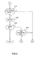
- step S118 it is checked whether or not full-depress shutter 1163 is depressed. When the shutter is not depressed, a flow gets back to step S105 of Fig.2 , but when the button is depressed, a flow proceeds to step S119 and then a subject is photographed.
- step S120 After this, it is checked whether or not a power of the camera is turned off in step S120 and when the power thereof is not turned off, a flow proceeds to step S121 and it is checked whether or not the face recognition mode setting is changed.
- the mode setting remains unchanged, a flow gets back to step S105 of Fig.2 , but when the face recognition mode setting is changed, a flow gets back to step S103 of Fig.3 .
- the camera power is turned off in step S120, series of shooting actions are finished in the face recognition mode.
- diaphragm 102 is set to a predetermined aperture value.
- Diaphragm 102 is usually set to the maximum aperture or near the maximum aperture at a time of turning the camera on. This is to focus on a specific subject readily by making depth of field shallow. Contrary to this, it is necessary that the depth of field be made deep whereby many subjects at a broad range be made recognizable in the face recognition mode.
- the aperture value is set to the minimum aperture or the vicinity of the minimum aperture.
- step S152 the focus lens is moved to the position of the hyperfocal distance as described before.
- the contrast method AF action wherein, when the power is turned on, usually, the focus lens is scanned over a predetermined range whereby a peak value of the evaluation value is detected.
- the face recognition action has a priority over the AF action in the face recognition mode. Therefore, when the focus lens has come to a stop at the closest distance or an infinity position due to causes of some kind, a person becomes overly out of focus so that the face recognition might become impossible. In this way, movement of the focus lens to the position of the hyperfocal distance enables to obtain image data focused on a subject from the beginning of the camera action and thus the face recognition can be quickly made.
- the image-taking lens may be caused to be moved to a predetermined position beforehand that is not based upon the lens.
- the predetermined position is a fixed position within 0.3 to 3m.
- the AE computation may be implemented.
- the reason for this is that the face recognition becomes impossible when subject brightness is too much or too dark to get shooting data. Therefore, prior to the face recognition action, first, the subject brightness is measured with AE computation section 1121 and the aperture or a shutter speed is adjusted such that the subject brightness becomes acceptable to some degree. Needless to say, in this initial setting, these three methods are not necessarily implemented as described herein and one or several combinations of the three methods may be selected as needed and implemented.
- a recognized subject is displayed as an identification display by a predetermined display method.
- Fig.6 shows one of examples of an embodiment of this display.
- Fig.6 shows that displays with squares of a thin solid line and a dotted line inside a face are recognized faces.
- the face with the dotted line is the largest face.
- a face at the closest distance may be displayed as an identification display from a result of the computation. Whether the largest or the closest face is displayed as an identification display is set via setting button 1164.
- step S202 it is judged whether or not a photo shooter selects a desired subject.
- a flow gets back to step S201, but when the photo shooter selects, in step S203, the thin solid line display of the selected face makes the dotted line display.
- step S204 it is judged whether or not the selected subject is locked. More specifically, after the subject is selected, depressing of setting button 1164 sets the subject to the subject being locked. With this, the selected subject is always set up as AF or AE area and thereby the AF and AE areas are prevented from moving to the other subject rather than the locked subject even if other subject becomes closer or larger since the locked subject moves.
- step S205 by changing over from the square broken line display of the locked subject to the square tick solid line display thereof, it is displayed as the identification display that the subject is being locked.
- step S206 it is judged whether or not the once set lock is released.
- the lock can be released by another depressing of setting button 1164. With this, the thick solid line display is changed to the broken line display whereby it is shown that the subject lock is released.
- a sign of subject identification is denoted by the square solid line, broken line and thick solid line and the sign may be distinguished from the subject lock identification and the face recognition identification by changing a color like red, blue etc, a shape such as a square, triangle, circle etc or pointing a locked subject with an arrow.
Landscapes
- Engineering & Computer Science (AREA)
- Multimedia (AREA)
- Signal Processing (AREA)
- General Engineering & Computer Science (AREA)
- Health & Medical Sciences (AREA)
- General Health & Medical Sciences (AREA)
- Oral & Maxillofacial Surgery (AREA)
- Human Computer Interaction (AREA)
- Physics & Mathematics (AREA)
- General Physics & Mathematics (AREA)
- Theoretical Computer Science (AREA)
- Studio Devices (AREA)
- Closed-Circuit Television Systems (AREA)
Claims (9)
- Digitalkamera mit:einer Abbildungsvorrichtung (103), die eingerichtet ist, ein Bild zu fotografieren, das einen Gegenstand enthält;einer Digitalsignal-Verarbeitungseinheit (106), die eingerichtet ist, Bilddaten, die von der Abbildungsvorrichtung ausgegeben wurden, bei einer ersten Bildfrequenz in einer ersten Speichervorrichtung (107) kontinuierlich zu speichern;einer Anzeigevorrichtung (109), die eingerichtet ist, die Bilddaten, die in der ersten Speichervorrichtung (107) gespeichert sind, zu lesen und anzuzeigen;dadurch gekennzeichnet, dassdie Digitalsignal-Verarbeitungseinheit (106) eingerichtet ist, die Bilddaten, die in der ersten Speichervorrichtung (107) gespeichert sind, kontinuierlich zu lesen und die Bilddaten bei einer zweiten Bildfrequenz in einer zweiten Speichervorrichtung (105) zu speichern, wobei die zweite Bildfrequenz kleiner als die erste Bildfrequenz ist; und dadurch dassdie Digitalkamera ferner eine Merkmalsextraktionsvorrichtung (112, 1123) aufweist, die eingerichtet ist, Merkmale des Gegenstandes bei der zweiten Bildfrequenz aus einem vorgegebenen Bereich der Bilddaten, die in der zweiten Speichervorrichtung (105) gespeichert sind, zu extrahieren.
- Digitalkamera nach Anspruch 1, wobei die Digitalsignal-Verarbeitungseinheit (106) eingerichtet ist, die Bilddaten derart auszudünnen, dass die Zahl von Pixeln der Bilddaten an eine vorgegebene zahl von Pixeln angepasst wird, die durch die Zahl von Anzeigepixeln der Anzeigevorrichtung festgelegt ist, und die ausgedünnten Bilddaten in der ersten Speichervorrichtung (107) zu speichern.
- Digitalkamera nach Anspruch 1 oder 2, wobei:die Digitalsignal-Verarbeitungseinheit (106) eingerichtet ist, in der zweiten Speichervorrichtung (105) nur einen vorgegebenen Bereich der Bilddaten, die in der ersten Speichervorrichtung (107) gespeichert sind, zu speichern.
- Digitalkamera nach einem der vorhergehenden Ansprüche, ferner mit:einer Belichtungsberechnungsvorrichtung (112, 1121), die eingerichtet ist, einen Belichtungsparameter während des Aufnahmevorgangs zu berechnen, wobei die Belichtungsberechnungsvorrichtung eingerichtet ist, den Belichtungsparameter auf Basis des Merkmalsausschnitts des Gegenstands zu berechnen, der durch die Merkmalsextraktionsvorrichtung (112, 1123) extrahiert wurde.
- Digitalkamera nach Anspruch 4, wobei der Merkmalsausschnitt, der durch die Merkmalsextraktionsvorrichtung extrahiert wurde, auf Bilddaten basiert, die von der Abbildungsvorrichtung (103) nach dem Abschluss einer Extraktionsmaßnahme durch die Merkmalsextraktionsvorrichtung (112, 1123) ausgegeben wurden.
- Digitalkamera nach einem der vorhergehenden Ansprüche, ferner mit:einer Erfassungsvorrichtung (112, 1122), die eingerichtet ist, einen Farbzustand auf einem zu fotografierenden Bildschirm zu erfassen, wobei die Erfassungsvorrichtung eingerichtet ist, einen Farbzustand auf dem Bildschirm nach Abschluss einer Extraktionsmaßnahme durch die Merkmalsextraktionsvorrichtung (112, 1121) zu erfassen.
- Digitalkamera nach Anspruch 6, wobei die Erfassungsvorrichtung (112, 1122) eingerichtet ist, einen Farbzustand auf dem Bildschirm auf Basis von Bilddaten zu erfassen, die von der Abbildungsvorrichtung nach Abschluss einer Extraktionsmaßnahme durch die Merkmalsextraktionsvorrichtung (112, 1122) ausgegeben wurden.
- Digitalkamera nach Anspruch 1, ferner mit:einer Abstandsberechnungsvorrichtung (112), die eingerichtet ist, einen Abstand zu einem Gegenstand zu berechnen, wobei die Abstandsberechnungsvorrichtung eingerichtet ist, einen Abstand zu einem Gegenstand entsprechend einem Merkmalsausschnitt zu berechnen, der durch die Merkmalsextraktionsvorrichtung (112, 1122) nach Abschluss einer Extraktionsmaßnahme durch die Merkmalsextraktionsvorrichtung extrahiert wurde.
- Digitalkamera nach Anspruch 8, wobei der Abstand zu einem Gegenstand entsprechend einem Merkmalsausschnitt auf Basis von Bilddaten berechnet wird, die von der Abbildungsvorrichtung (103) nach Abschluss einer Extraktionsmaßnahme durch die Merkmalsextraktionsvorrichtung (112, 1123) ausgegeben wurden.
Applications Claiming Priority (6)
| Application Number | Priority Date | Filing Date | Title |
|---|---|---|---|
| JP2003351777A JP4254467B2 (ja) | 2003-10-10 | 2003-10-10 | デジタルカメラ |
| JP2003351777 | 2003-10-10 | ||
| JP2003351778A JP4305119B2 (ja) | 2003-10-10 | 2003-10-10 | デジタルカメラ |
| JP2003351779 | 2003-10-10 | ||
| JP2003351779A JP4306399B2 (ja) | 2003-10-10 | 2003-10-10 | デジタルカメラ |
| JP2003351778 | 2003-10-10 |
Publications (3)
| Publication Number | Publication Date |
|---|---|
| EP1522952A2 EP1522952A2 (de) | 2005-04-13 |
| EP1522952A3 EP1522952A3 (de) | 2006-03-22 |
| EP1522952B1 true EP1522952B1 (de) | 2013-04-17 |
Family
ID=34317259
Family Applications (1)
| Application Number | Title | Priority Date | Filing Date |
|---|---|---|---|
| EP04256236.3A Expired - Lifetime EP1522952B1 (de) | 2003-10-10 | 2004-10-08 | Digitalkamera |
Country Status (3)
| Country | Link |
|---|---|
| US (1) | US8159561B2 (de) |
| EP (1) | EP1522952B1 (de) |
| CN (1) | CN100499747C (de) |
Families Citing this family (29)
| Publication number | Priority date | Publication date | Assignee | Title |
|---|---|---|---|---|
| JP4674471B2 (ja) | 2005-01-18 | 2011-04-20 | 株式会社ニコン | デジタルカメラ |
| JP4193804B2 (ja) * | 2005-02-03 | 2008-12-10 | カシオ計算機株式会社 | 撮像装置、画像記憶装置、撮像方法、記憶方法及びプログラム |
| US20060187313A1 (en) * | 2005-02-22 | 2006-08-24 | Pandit Amol S | Method and apparatus for reduced image capture delay in a digital camera |
| JP2006345296A (ja) * | 2005-06-09 | 2006-12-21 | Fujifilm Holdings Corp | 画像表示装置及びソート方法 |
| JP4747003B2 (ja) * | 2005-06-22 | 2011-08-10 | 富士フイルム株式会社 | 自動合焦制御装置およびその制御方法 |
| JP2007010898A (ja) * | 2005-06-29 | 2007-01-18 | Casio Comput Co Ltd | 撮像装置及びそのプログラム |
| JP2007011200A (ja) * | 2005-07-04 | 2007-01-18 | Konica Minolta Photo Imaging Inc | 撮像装置 |
| EP1742462A1 (de) * | 2005-07-08 | 2007-01-10 | Koninklijke Philips Electronics N.V. | Digitale Bildaufnahmevorrichtung mit einem Abtastungsblitz |
| JP2007036928A (ja) * | 2005-07-29 | 2007-02-08 | Sharp Corp | 携帯情報端末装置 |
| US7412158B2 (en) * | 2005-08-08 | 2008-08-12 | Nokia Corporation | Deeper depth of field for video |
| JP2007065290A (ja) * | 2005-08-31 | 2007-03-15 | Nikon Corp | オートフォーカス装置 |
| JP4914045B2 (ja) * | 2005-09-07 | 2012-04-11 | キヤノン株式会社 | 撮像装置及び撮像装置の制御方法 |
| JP4533860B2 (ja) * | 2006-03-09 | 2010-09-01 | 富士フイルム株式会社 | 撮影装置及び露出制御方法 |
| JP2007311861A (ja) * | 2006-05-16 | 2007-11-29 | Fujifilm Corp | 撮影装置及び方法 |
| JP4110178B2 (ja) | 2006-07-03 | 2008-07-02 | キヤノン株式会社 | 撮像装置及びその制御方法及びプログラム及び記憶媒体 |
| US7830445B2 (en) * | 2006-07-25 | 2010-11-09 | Canon Kabushiki Kaisha | Image-pickup apparatus and focus control method for the same |
| US9596401B2 (en) * | 2006-10-02 | 2017-03-14 | Sony Corporation | Focusing an image based on a direction of a face of a user |
| JP4810416B2 (ja) * | 2006-12-19 | 2011-11-09 | Hoya株式会社 | 焦点調節装置を備えたカメラ |
| JP4286292B2 (ja) * | 2007-01-30 | 2009-06-24 | 三洋電機株式会社 | 電子カメラ |
| JP5056061B2 (ja) * | 2007-02-22 | 2012-10-24 | 株式会社ニコン | 撮像装置 |
| CN101731004B (zh) * | 2007-04-23 | 2012-07-04 | 夏普株式会社 | 摄像装置、控制方法以及便携式终端 |
| CN102265602A (zh) | 2008-12-26 | 2011-11-30 | 松下电器产业株式会社 | 图像拍摄装置 |
| JP2011101202A (ja) * | 2009-11-06 | 2011-05-19 | Sanyo Electric Co Ltd | 電子カメラ |
| JP2011234015A (ja) | 2010-04-26 | 2011-11-17 | Kyocera Corp | 端末装置 |
| JP5639832B2 (ja) * | 2010-09-30 | 2014-12-10 | 任天堂株式会社 | 情報処理プログラム、情報処理方法、情報処理システム、及び情報処理装置 |
| TW201228360A (en) * | 2010-12-22 | 2012-07-01 | Largan Precision Co Ltd | Stereo display device |
| JP5536010B2 (ja) * | 2011-11-02 | 2014-07-02 | カシオ計算機株式会社 | 電子カメラ、撮像制御プログラム及び撮像制御方法 |
| JP6159097B2 (ja) * | 2013-02-07 | 2017-07-05 | キヤノン株式会社 | 画像処理装置、撮像装置、制御方法、及びプログラム |
| KR20160073866A (ko) * | 2014-12-17 | 2016-06-27 | 삼성전자주식회사 | 홍채 인식 장치, 이를 포함하는 홍채 인식 시스템 및 상기 홍채 인식 시스템의 동작 방법 |
Family Cites Families (55)
| Publication number | Priority date | Publication date | Assignee | Title |
|---|---|---|---|---|
| US4580160A (en) * | 1984-03-22 | 1986-04-01 | Fuji Photo Film Co., Ltd. | Color image sensor with improved resolution having time delays in a plurality of output lines |
| JPH0789059B2 (ja) * | 1987-01-14 | 1995-09-27 | 株式会社日立製作所 | 視覚センサシステム |
| US5005086A (en) * | 1988-03-04 | 1991-04-02 | Sony Corporation | Focus control apparatus having two focusing speeds |
| US5347371A (en) * | 1990-11-29 | 1994-09-13 | Hitachi, Ltd. | Video camera with extraction unit for extracting specific portion of video signal |
| DE69221665T2 (de) * | 1991-05-23 | 1997-12-11 | Fuji Photo Film Co Ltd | Verfahren zur Ermittlung einer Belichtung |
| KR100276681B1 (ko) * | 1992-11-07 | 2001-01-15 | 이데이 노부유끼 | 비디오 카메라 시스템 |
| JP3327651B2 (ja) * | 1993-11-25 | 2002-09-24 | キヤノン株式会社 | 視線検出機能付光学装置 |
| US5559551A (en) * | 1994-05-30 | 1996-09-24 | Sony Corporation | Subject tracking apparatus |
| JPH0887600A (ja) * | 1994-09-19 | 1996-04-02 | Topcon Corp | 特徴抽出装置 |
| KR100371428B1 (ko) * | 1995-03-28 | 2003-04-08 | 마츠시타 덴끼 산교 가부시키가이샤 | 화상기록장치및화상재생장치 |
| JP3279913B2 (ja) | 1996-03-18 | 2002-04-30 | 株式会社東芝 | 人物認証装置、特徴点抽出装置及び特徴点抽出方法 |
| US5920644A (en) * | 1996-06-06 | 1999-07-06 | Fujitsu Limited | Apparatus and method of recognizing pattern through feature selection by projecting feature vector on partial eigenspace |
| US5842059A (en) * | 1996-07-22 | 1998-11-24 | Canon Kabushiki Kaisha | Automatic focus adjusting device |
| JP3534551B2 (ja) * | 1996-09-20 | 2004-06-07 | シャープ株式会社 | 動き検出装置 |
| JP3581513B2 (ja) * | 1997-01-23 | 2004-10-27 | キヤノン株式会社 | 光学機器 |
| JP3469031B2 (ja) | 1997-02-18 | 2003-11-25 | 株式会社東芝 | 顔画像登録装置及びその方法 |
| JP3934786B2 (ja) * | 1997-05-27 | 2007-06-20 | 株式会社リコー | 画像入力装置 |
| JPH1132295A (ja) * | 1997-07-09 | 1999-02-02 | Olympus Optical Co Ltd | デジタルカラープリンタ、デジタルカメラ及びそれらを用いたデジタルカラープリントシステム |
| JP4588127B2 (ja) * | 1997-09-05 | 2010-11-24 | ソニー株式会社 | ディスク記録方法及びディスク記録装置 |
| JP3096684B2 (ja) * | 1998-03-25 | 2000-10-10 | 三洋電機株式会社 | デジタルカメラ |
| US6167200A (en) * | 1998-08-03 | 2000-12-26 | Minolta Co., Ltd. | Exposure operation mechanism of camera |
| US6819356B1 (en) * | 1998-11-18 | 2004-11-16 | Casio Computer Co., Ltd. | Image search method in electronic still camera with GPS reception function |
| JP3939457B2 (ja) * | 1999-03-12 | 2007-07-04 | カシオ計算機株式会社 | 電子スチルカメラ及びその制御方法 |
| JP2001036801A (ja) * | 1999-07-23 | 2001-02-09 | Sharp Corp | 撮像装置 |
| JP4043657B2 (ja) * | 1999-09-06 | 2008-02-06 | ペンタックス株式会社 | 写真測量用画像処理装置、写真測量用画像処理方法および写真測量用画像処理プログラムを格納した記憶媒体 |
| JP2001128051A (ja) * | 1999-10-27 | 2001-05-11 | Ricoh Co Ltd | 撮像装置 |
| JP2001201779A (ja) | 2000-01-20 | 2001-07-27 | Olympus Optical Co Ltd | カメラ |
| EP1124379A3 (de) * | 2000-02-09 | 2011-08-17 | Canon Kabushiki Kaisha | Verfahren und Gerät für die Unterdrückung von Teilen einer Aufzeichnung |
| US6940545B1 (en) | 2000-02-28 | 2005-09-06 | Eastman Kodak Company | Face detecting camera and method |
| JP2001268509A (ja) * | 2000-03-17 | 2001-09-28 | Omron Corp | 画像記録装置及び画像記録システム |
| JP4472114B2 (ja) | 2000-05-16 | 2010-06-02 | 富士フイルム株式会社 | 画像撮像装置 |
| JP4726321B2 (ja) * | 2000-05-31 | 2011-07-20 | 小糸工業株式会社 | ホーム監視装置 |
| JP2002051255A (ja) | 2000-07-31 | 2002-02-15 | Olympus Optical Co Ltd | 主要被写体検出カメラ |
| JP4017335B2 (ja) * | 2000-10-25 | 2007-12-05 | 三菱電機株式会社 | 映像信号の有効期間検出回路 |
| US20020081003A1 (en) * | 2000-12-27 | 2002-06-27 | Sobol Robert E. | System and method for automatically enhancing graphical images |
| JP4397128B2 (ja) | 2001-01-31 | 2010-01-13 | 富士フイルム株式会社 | 画像記録方法 |
| US7664296B2 (en) * | 2001-01-31 | 2010-02-16 | Fujifilm Corporation | Image recording method and system, image transmitting method, and image recording apparatus |
| JP4783985B2 (ja) * | 2001-02-28 | 2011-09-28 | 日本電気株式会社 | 映像処理装置、映像表示装置及びそれに用いる映像処理方法並びにそのプログラム |
| US6876412B2 (en) * | 2001-04-06 | 2005-04-05 | Sony Corporation | Guest-host liquid crystal element with removable polarizer |
| JP2002333652A (ja) | 2001-05-10 | 2002-11-22 | Oki Electric Ind Co Ltd | 撮影装置及び再生装置 |
| JP4124404B2 (ja) * | 2001-05-17 | 2008-07-23 | 富士フイルム株式会社 | 撮像装置、画像処理装置、画像処理方法、及びプログラム |
| JP4177598B2 (ja) * | 2001-05-25 | 2008-11-05 | 株式会社東芝 | 顔画像記録装置、情報管理システム、顔画像記録方法、及び情報管理方法 |
| KR100429874B1 (ko) * | 2001-07-20 | 2004-05-04 | 삼성전자주식회사 | 파노라마/워터글라스 기능 구현을 위한 영상 처리 장치 및그 방법 |
| US7106366B2 (en) * | 2001-12-19 | 2006-09-12 | Eastman Kodak Company | Image capture system incorporating metadata to facilitate transcoding |
| JP3744464B2 (ja) * | 2002-05-20 | 2006-02-08 | ソニー株式会社 | 信号記録再生装置及び方法、信号再生装置及び方法、並びにプログラム及び記録媒体 |
| JP2003348462A (ja) * | 2002-05-27 | 2003-12-05 | Olympus Optical Co Ltd | カメラ及び撮像素子ユニット |
| JP4008778B2 (ja) * | 2002-07-31 | 2007-11-14 | 株式会社リコー | 撮像装置 |
| US7391463B2 (en) * | 2002-08-06 | 2008-06-24 | Olympus Corporation | Image sensing apparatus having distance measuring unit and control method thereof |
| JP4179079B2 (ja) * | 2002-08-30 | 2008-11-12 | 株式会社ニコン | 電子カメラ及びその制御プログラム |
| JP4478377B2 (ja) * | 2002-09-03 | 2010-06-09 | キヤノン株式会社 | 自動合焦方法及び撮像装置 |
| EP1403759A3 (de) * | 2002-09-17 | 2007-04-04 | Sharp Kabushiki Kaisha | Elektronisches gerät mit zwei- und dreidimensionalen Anzeigefunktionen |
| JP3903948B2 (ja) * | 2002-09-25 | 2007-04-11 | ソニー株式会社 | レンズ調芯機構、レンズ装置及び撮像装置 |
| EP1688884B1 (de) | 2002-12-11 | 2009-04-01 | FUJIFILM Corporation | Bildaufnahmevorrichtung |
| US7359529B2 (en) * | 2003-03-06 | 2008-04-15 | Samsung Electronics Co., Ltd. | Image-detectable monitoring system and method for using the same |
| JP4478414B2 (ja) * | 2003-07-31 | 2010-06-09 | キヤノン株式会社 | 投射型画像表示装置 |
-
2004
- 2004-10-01 US US10/954,613 patent/US8159561B2/en active Active
- 2004-10-08 EP EP04256236.3A patent/EP1522952B1/de not_active Expired - Lifetime
- 2004-10-10 CN CNB2004100850500A patent/CN100499747C/zh not_active Expired - Lifetime
Also Published As
| Publication number | Publication date |
|---|---|
| CN1607817A (zh) | 2005-04-20 |
| CN100499747C (zh) | 2009-06-10 |
| US20050088538A1 (en) | 2005-04-28 |
| EP1522952A2 (de) | 2005-04-13 |
| EP1522952A3 (de) | 2006-03-22 |
| US8159561B2 (en) | 2012-04-17 |
Similar Documents
| Publication | Publication Date | Title |
|---|---|---|
| EP1522952B1 (de) | Digitalkamera | |
| CN1604621B (zh) | 摄像装置及其控制方法 | |
| JP4196714B2 (ja) | デジタルカメラ | |
| US8830343B2 (en) | Digital camera | |
| US9147106B2 (en) | Digital camera system | |
| US20040119851A1 (en) | Face recognition method, face recognition apparatus, face extraction method, and image pickup apparatus | |
| US8411159B2 (en) | Method of detecting specific object region and digital camera | |
| JP2004317699A (ja) | デジタルカメラ | |
| JP2004320286A (ja) | デジタルカメラ | |
| JP5171468B2 (ja) | 撮像装置及び撮像装置の制御方法 | |
| JP2004320285A (ja) | デジタルカメラ | |
| CN108289170B (zh) | 能够检测计量区域的拍照装置、方法及计算机可读介质 | |
| JP2001215404A (ja) | 主要被写体検出機能を有するカメラ | |
| JP2003289468A (ja) | 撮像装置 | |
| JP2005223658A (ja) | デジタルカメラ | |
| JP4254467B2 (ja) | デジタルカメラ | |
| JP2008172732A (ja) | 撮像装置及びその制御方法、プログラム、 | |
| US20070002463A1 (en) | Image capturing apparatus | |
| JP4306399B2 (ja) | デジタルカメラ | |
| JP4305119B2 (ja) | デジタルカメラ | |
| JP2007067934A (ja) | 撮像装置及びその制御方法 | |
| JP2012200023A (ja) | 電子カメラ | |
| JP2005223657A (ja) | デジタルカメラ | |
| JP2008017211A (ja) | 撮像装置、撮像装置の制御方法、プログラム及び記憶媒体 |
Legal Events
| Date | Code | Title | Description |
|---|---|---|---|
| PUAI | Public reference made under article 153(3) epc to a published international application that has entered the european phase |
Free format text: ORIGINAL CODE: 0009012 |
|
| AK | Designated contracting states |
Kind code of ref document: A2 Designated state(s): AT BE BG CH CY CZ DE DK EE ES FI FR GB GR HU IE IT LI LU MC NL PL PT RO SE SI SK TR |
|
| AX | Request for extension of the european patent |
Extension state: AL HR LT LV MK |
|
| PUAL | Search report despatched |
Free format text: ORIGINAL CODE: 0009013 |
|
| AK | Designated contracting states |
Kind code of ref document: A3 Designated state(s): AT BE BG CH CY CZ DE DK EE ES FI FR GB GR HU IE IT LI LU MC NL PL PT RO SE SI SK TR |
|
| AX | Request for extension of the european patent |
Extension state: AL HR LT LV MK |
|
| RIC1 | Information provided on ipc code assigned before grant |
Ipc: H04N 1/00 20060101ALI20050119BHEP Ipc: G06K 9/00 20060101AFI20060131BHEP |
|
| RAP1 | Party data changed (applicant data changed or rights of an application transferred) |
Owner name: NIKON CORPORATION |
|
| 17P | Request for examination filed |
Effective date: 20060920 |
|
| AKX | Designation fees paid |
Designated state(s): DE FR GB |
|
| 17Q | First examination report despatched |
Effective date: 20070221 |
|
| RAP1 | Party data changed (applicant data changed or rights of an application transferred) |
Owner name: NIKON CORPORATION |
|
| GRAP | Despatch of communication of intention to grant a patent |
Free format text: ORIGINAL CODE: EPIDOSNIGR1 |
|
| GRAS | Grant fee paid |
Free format text: ORIGINAL CODE: EPIDOSNIGR3 |
|
| GRAA | (expected) grant |
Free format text: ORIGINAL CODE: 0009210 |
|
| AK | Designated contracting states |
Kind code of ref document: B1 Designated state(s): DE FR GB |
|
| REG | Reference to a national code |
Ref country code: GB Ref legal event code: FG4D |
|
| REG | Reference to a national code |
Ref country code: DE Ref legal event code: R096 Ref document number: 602004041764 Country of ref document: DE Effective date: 20130606 |
|
| PLBE | No opposition filed within time limit |
Free format text: ORIGINAL CODE: 0009261 |
|
| STAA | Information on the status of an ep patent application or granted ep patent |
Free format text: STATUS: NO OPPOSITION FILED WITHIN TIME LIMIT |
|
| 26N | No opposition filed |
Effective date: 20140120 |
|
| REG | Reference to a national code |
Ref country code: DE Ref legal event code: R097 Ref document number: 602004041764 Country of ref document: DE Effective date: 20140120 |
|
| REG | Reference to a national code |
Ref country code: FR Ref legal event code: PLFP Year of fee payment: 13 |
|
| REG | Reference to a national code |
Ref country code: FR Ref legal event code: PLFP Year of fee payment: 14 |
|
| REG | Reference to a national code |
Ref country code: FR Ref legal event code: PLFP Year of fee payment: 15 |
|
| REG | Reference to a national code |
Ref country code: DE Ref legal event code: R079 Ref document number: 602004041764 Country of ref document: DE Free format text: PREVIOUS MAIN CLASS: G06K0009000000 Ipc: G06V0010000000 |
|
| P01 | Opt-out of the competence of the unified patent court (upc) registered |
Effective date: 20230517 |
|
| PGFP | Annual fee paid to national office [announced via postgrant information from national office to epo] |
Ref country code: GB Payment date: 20230831 Year of fee payment: 20 |
|
| PGFP | Annual fee paid to national office [announced via postgrant information from national office to epo] |
Ref country code: FR Payment date: 20230911 Year of fee payment: 20 |
|
| PGFP | Annual fee paid to national office [announced via postgrant information from national office to epo] |
Ref country code: DE Payment date: 20230830 Year of fee payment: 20 |
|
| REG | Reference to a national code |
Ref country code: DE Ref legal event code: R071 Ref document number: 602004041764 Country of ref document: DE |
|
| REG | Reference to a national code |
Ref country code: GB Ref legal event code: PE20 Expiry date: 20241007 |
|
| PG25 | Lapsed in a contracting state [announced via postgrant information from national office to epo] |
Ref country code: GB Free format text: LAPSE BECAUSE OF EXPIRATION OF PROTECTION Effective date: 20241007 |
|
| PG25 | Lapsed in a contracting state [announced via postgrant information from national office to epo] |
Ref country code: GB Free format text: LAPSE BECAUSE OF EXPIRATION OF PROTECTION Effective date: 20241007 |