EP1522814A2 - Echangeur de chaleur, en particulier pour véhicule automobile - Google Patents
Echangeur de chaleur, en particulier pour véhicule automobile Download PDFInfo
- Publication number
- EP1522814A2 EP1522814A2 EP04021988A EP04021988A EP1522814A2 EP 1522814 A2 EP1522814 A2 EP 1522814A2 EP 04021988 A EP04021988 A EP 04021988A EP 04021988 A EP04021988 A EP 04021988A EP 1522814 A2 EP1522814 A2 EP 1522814A2
- Authority
- EP
- European Patent Office
- Prior art keywords
- edge
- heat exchanger
- edges
- longitudinal
- motor vehicles
- Prior art date
- Legal status (The legal status is an assumption and is not a legal conclusion. Google has not performed a legal analysis and makes no representation as to the accuracy of the status listed.)
- Withdrawn
Links
- 229910000679 solder Inorganic materials 0.000 claims abstract description 12
- 238000000034 method Methods 0.000 claims description 6
- 238000005476 soldering Methods 0.000 claims description 5
- 238000007789 sealing Methods 0.000 claims description 4
- XAGFODPZIPBFFR-UHFFFAOYSA-N aluminium Chemical compound [Al] XAGFODPZIPBFFR-UHFFFAOYSA-N 0.000 claims description 3
- 229910052782 aluminium Inorganic materials 0.000 claims description 3
- BUHVIAUBTBOHAG-FOYDDCNASA-N (2r,3r,4s,5r)-2-[6-[[2-(3,5-dimethoxyphenyl)-2-(2-methylphenyl)ethyl]amino]purin-9-yl]-5-(hydroxymethyl)oxolane-3,4-diol Chemical compound COC1=CC(OC)=CC(C(CNC=2C=3N=CN(C=3N=CN=2)[C@H]2[C@@H]([C@H](O)[C@@H](CO)O2)O)C=2C(=CC=CC=2)C)=C1 BUHVIAUBTBOHAG-FOYDDCNASA-N 0.000 description 2
- 238000011161 development Methods 0.000 description 2
- 230000018109 developmental process Effects 0.000 description 2
- 239000007787 solid Substances 0.000 description 2
- 230000015572 biosynthetic process Effects 0.000 description 1
- 238000001816 cooling Methods 0.000 description 1
- 238000005520 cutting process Methods 0.000 description 1
- 238000005516 engineering process Methods 0.000 description 1
- 238000004519 manufacturing process Methods 0.000 description 1
- 239000000463 material Substances 0.000 description 1
- 238000003825 pressing Methods 0.000 description 1
- 239000013589 supplement Substances 0.000 description 1
Images


Classifications
-
- F—MECHANICAL ENGINEERING; LIGHTING; HEATING; WEAPONS; BLASTING
- F28—HEAT EXCHANGE IN GENERAL
- F28D—HEAT-EXCHANGE APPARATUS, NOT PROVIDED FOR IN ANOTHER SUBCLASS, IN WHICH THE HEAT-EXCHANGE MEDIA DO NOT COME INTO DIRECT CONTACT
- F28D1/00—Heat-exchange apparatus having stationary conduit assemblies for one heat-exchange medium only, the media being in contact with different sides of the conduit wall, in which the other heat-exchange medium is a large body of fluid, e.g. domestic or motor car radiators
- F28D1/02—Heat-exchange apparatus having stationary conduit assemblies for one heat-exchange medium only, the media being in contact with different sides of the conduit wall, in which the other heat-exchange medium is a large body of fluid, e.g. domestic or motor car radiators with heat-exchange conduits immersed in the body of fluid
- F28D1/04—Heat-exchange apparatus having stationary conduit assemblies for one heat-exchange medium only, the media being in contact with different sides of the conduit wall, in which the other heat-exchange medium is a large body of fluid, e.g. domestic or motor car radiators with heat-exchange conduits immersed in the body of fluid with tubular conduits
- F28D1/053—Heat-exchange apparatus having stationary conduit assemblies for one heat-exchange medium only, the media being in contact with different sides of the conduit wall, in which the other heat-exchange medium is a large body of fluid, e.g. domestic or motor car radiators with heat-exchange conduits immersed in the body of fluid with tubular conduits the conduits being straight
- F28D1/0535—Heat-exchange apparatus having stationary conduit assemblies for one heat-exchange medium only, the media being in contact with different sides of the conduit wall, in which the other heat-exchange medium is a large body of fluid, e.g. domestic or motor car radiators with heat-exchange conduits immersed in the body of fluid with tubular conduits the conduits being straight the conduits having a non-circular cross-section
-
- F—MECHANICAL ENGINEERING; LIGHTING; HEATING; WEAPONS; BLASTING
- F28—HEAT EXCHANGE IN GENERAL
- F28F—DETAILS OF HEAT-EXCHANGE AND HEAT-TRANSFER APPARATUS, OF GENERAL APPLICATION
- F28F9/00—Casings; Header boxes; Auxiliary supports for elements; Auxiliary members within casings
- F28F9/001—Casings in the form of plate-like arrangements; Frames enclosing a heat exchange core
-
- F—MECHANICAL ENGINEERING; LIGHTING; HEATING; WEAPONS; BLASTING
- F28—HEAT EXCHANGE IN GENERAL
- F28F—DETAILS OF HEAT-EXCHANGE AND HEAT-TRANSFER APPARATUS, OF GENERAL APPLICATION
- F28F2275/00—Fastening; Joining
- F28F2275/14—Fastening; Joining by using form fitting connection, e.g. with tongue and groove
Definitions
- the invention relates to a heat exchanger, in particular for motor vehicles, its components made of flat tubes, corrugated fins, tube sheets with Openings for receiving the ends of the flat tubes and with connecting longitudinal and Crossing edges, as well as with four corners, exist, and off Collection boxes with two longitudinal walls for connection to the Connecting longitudinal edges, from side parts with caps, to the closure the lateral openings of the collecting boxes, wherein the closure caps a Have edge and wherein all parts are made of aluminum, the is suitably coated with solder, for metallic connection by means of a Soldering process.
- This heat exchanger was registered with the DPMA on July 22, 2003 and received the file number DE 103 33 150.6.
- the object of the invention consists in the development of this state of the Technology.
- a heat exchanger is to be proposed, whose Manufacturability, in particular with regard to the creation of denser and stronger Soldered, further simplified or improved.
- contour - cutout Can be further developed with a flange-like fold to the Increase connection area with the cap. This measure can be provided in particular when the sheet thickness of the tube sheet is reduced shall be.
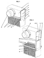
- a heat exchanger for motor vehicles is shown, the components of flat tubes 1 , corrugated fins 2 , tube sheets 3 with openings 4 for receiving the ends of the flat tubes 1 and with horrslhacks - and connecting transverse edges 5 , 6 , which form four corner regions exist.
- the heat exchanger consists of collecting boxes 7 with two longitudinal walls 8 , 9 for connection to the connecting longitudinal edges 5 and side parts 10 with sealing caps 11 , for closing the lateral openings of the collecting boxes 7 , wherein the closure caps 11 have a bevelled edge 14 .
- means 15 for fixing the heat exchanger at the edge of the collecting tank 6 and the edge 14 of the closure cap 11 are arranged, which cooperate. All mentioned parts of the heat exchanger are made of aluminum sheet, which is suitably coated with solder, for the metallic connection by means of a soldering process.
- the longitudinal walls 8 , 9 of the manifolds 7 are arranged between the connecting longitudinal edges 5 of the tubesheets 3 , wherein projections 20 are provided on the longitudinal walls 8 , 9 , stuck in corresponding openings 30 in the tube sheets 3 .
- the connecting transverse edges 6 of the tubesheets 3 have a contour cutout 40 which forms a tight and firm soldered connection with the closure caps 11 .
- the projections 20 have a slightly conical shape, so that a certain guidance is ensured in the openings 30 and that at the same time it is ensured that the projections 20 fit tightly against the edge of the openings 30 .
- the projections 20 and the openings 30 are arranged at appropriate intervals in order to fulfill their function.
- the openings 30 in the tube sheet 3 are preferably arranged between the openings 4 for the flat tube ends, so that a maximum depth of the tube - rib block is ensured. Furthermore, they are preferably located directly on the connecting longitudinal edge 5 .
- the contour cutout 40 of the connecting transverse edges 6 is provided between the connecting longitudinal edges 5 .
- the contour cutout 40 corresponds approximately to the Kontor the cap 11 so that a solid and tight solder joint is achieved.
- the contour of the cutout thus depends on the selected contour of the closure cap 11 .
- FIG. 2 in conjunction with FIGS. 9 and 10 , shows the contour cutout 40 is formed in the exemplary embodiment so that the two connecting longitudinal edges 5 slightly above the remaining connecting transverse edge 6 of the tube sheet 3 protrude.
- the protruding connecting longitudinal edges have the reference numeral 51 in FIGS. 2, 9 and 10.
- a graduation 50 whose size approximately corresponds to the sheet thickness of the collecting boxes 7 , or the sheet thickness of the longitudinal walls 8 , 9 , also belongs on both sides.
- the projecting connecting longitudinal edges 51 thus each receive a projection 20 between them and the edge 14 of the closure cap 11 .
- the connection between the connecting transverse edge 5 and the closure cap 11 as shown in FIG. 12, be formed without a flange. 13 and 14, however, show a flange 41 , wherein in Fig. 13, the flange is directed downward and in Fig. 14 upwards to create a solid and tight solder joint even with thinner tube sheets 3 .
- a cutout 16 is provided, into which a flap 17 has been bent on the transverse wall of the collecting box 7 in order to provide a provisional holding of the heat exchanger in the production phase.
- the partial longitudinal section shown in FIG. 11 runs exactly through the mentioned means 15 for fixing and shows the tab 17 in the already bent state.
- the assembly process of the heat exchanger is in the described embodiment as follows:
- the flat tubes 1 are alternately assembled with the corrugated fins 2 to the so-called rib-tube block.
- the side parts 10 are attached to the caps 11 .
- a tube plate 3 is raised at each end of the flat tubes 1 , after which the ends of the flat tubes 1 are inserted into the openings 4 of the tubesheets 3 .
- the collecting boxes 7 are placed on the tubesheets 3 , wherein the projections 20 are respectively inserted into the openings 30 .
- the headers 7 are thereby fixed in their longitudinal direction.
- a pressing of the connecting longitudinal edges 5 of the tube sheet 3 to the longitudinal walls 8 , 9 of the collecting tank 7 is achieved.
- the mentioned means 15 are used for fixing, which are preferably formed in the form of the tabs 17 also mentioned, which are bent into the cutout 16 at the edge 14 of the cap 11 .
- the heat exchanger is thus a self-contained unit that can be prepared for the soldering process.
- FIG. 7 differs from FIG. 8 in that FIG. 7 shows a section in the region of a flat tube 1 and FIG. 8 shows another section in the region of the projections 20 .
- FIGS. 5 and 6 also differ only because of the different cutting planes.
- a heat exchanging medium into the collecting box 7 occurs, for example in the positions shown in Figs. 1 and 2 nozzles 70, and distributed to the flat tubes 1 to pass through to it.
- An identical or similar collection box 7 is located on the one side not shown (in the longitudinal direction of the flat tubes) of the heat exchanger and another not shown nozzle is arranged either on the shown or not shown collection box 7 to dissipate the heat exchanging medium. Cooling air flows through the corrugated fins 2 and is in heat exchanging relationship with the mentioned medium.
- only one side member 10 is shown, it being understood that a second side member is present on the second side not shown (transverse to the flat tubes) that is identical at least with respect to the features described herein.
- the closure caps 11 are formed as individual parts, as has also been provided in the non-prepublished application. Even with such heat exchangers, a contour cutout 40 is provided in the connecting transverse edges 6 of the tubesheets 3 . Further, at the edges of the longitudinal walls 8 , 9 of the manifolds 7 projections 20 are provided, which are inserted into corresponding openings 30 in the tube sheets 3 . The mentioned openings 30 are not recognizable in FIG. 15, for which reason reference is made to FIG. 9 in this regard.
- the fixing means 15 which are required in this embodiment rather than in the first embodiment, consist of clips formed on the edge 14 of the closure cap 11 .
Landscapes
- Engineering & Computer Science (AREA)
- Physics & Mathematics (AREA)
- Thermal Sciences (AREA)
- Mechanical Engineering (AREA)
- General Engineering & Computer Science (AREA)
- Details Of Heat-Exchange And Heat-Transfer (AREA)
- Heat-Exchange Devices With Radiators And Conduit Assemblies (AREA)
Applications Claiming Priority (2)
| Application Number | Priority Date | Filing Date | Title |
|---|---|---|---|
| DE10347180 | 2003-10-10 | ||
| DE10347180A DE10347180A1 (de) | 2003-10-10 | 2003-10-10 | Wärmeaustauscher, insbesondere für Kraftfahrzeuge |
Publications (2)
| Publication Number | Publication Date |
|---|---|
| EP1522814A2 true EP1522814A2 (fr) | 2005-04-13 |
| EP1522814A3 EP1522814A3 (fr) | 2012-12-12 |
Family
ID=34306360
Family Applications (1)
| Application Number | Title | Priority Date | Filing Date |
|---|---|---|---|
| EP04021988A Withdrawn EP1522814A3 (fr) | 2003-10-10 | 2004-09-16 | Echangeur de chaleur, en particulier pour véhicule automobile |
Country Status (3)
| Country | Link |
|---|---|
| US (1) | US7032656B2 (fr) |
| EP (1) | EP1522814A3 (fr) |
| DE (1) | DE10347180A1 (fr) |
Cited By (5)
| Publication number | Priority date | Publication date | Assignee | Title |
|---|---|---|---|---|
| FR2902506A1 (fr) * | 2006-06-19 | 2007-12-21 | Valeo Systemes Thermiques | Echangeur de chaleur ayant au moins une traverse d'extremite et son procede d'assemblage |
| EP1923653A1 (fr) * | 2006-11-14 | 2008-05-21 | Modine Manufacturing Company | Échangeur de chaleur |
| EP1923654A1 (fr) * | 2006-11-18 | 2008-05-21 | Modine Manufacturing Company | Échangeur de chaleur |
| FR3056724A1 (fr) * | 2016-09-28 | 2018-03-30 | Valeo Systemes Thermiques | Echangeur thermique, notamment pour vehicule automobile |
| EP3916338A1 (fr) * | 2020-05-26 | 2021-12-01 | Valeo Systemes Thermiques | Échangeur de chaleur |
Families Citing this family (22)
| Publication number | Priority date | Publication date | Assignee | Title |
|---|---|---|---|---|
| EP1771697B1 (fr) * | 2004-07-16 | 2017-06-21 | MAHLE Behr GmbH & Co. KG | Echangeur thermique, boite destinee a recevoir un fluide pour un echangeur thermique, et procede de production de cette boite |
| US20060113069A1 (en) * | 2004-11-29 | 2006-06-01 | Denso Corporation | Heat exchanger |
| DE102005013922A1 (de) * | 2005-03-26 | 2006-09-28 | Modine Manufacturing Co., Racine | Wärmetauscher, insbesondere Ladeluftkühler |
| WO2007031274A1 (fr) * | 2005-09-12 | 2007-03-22 | Behr Gmbh & Co. Kg | Echangeur thermique, notamment refroidisseur d'air de suralimentation ou refroidisseur de gaz d'echappement pour un moteur a combustion interne d'un vehicule automobile |
| DE102006058096A1 (de) * | 2006-12-09 | 2008-06-12 | Modine Manufacturing Co., Racine | Ganz-Metall-Wärmetauscher |
| US20080156455A1 (en) * | 2006-12-14 | 2008-07-03 | Powers Michael V | Heat exchanger manifolds with retention tabs |
| DE102008013134A1 (de) * | 2008-03-07 | 2009-09-10 | Audi Ag | Wärmetauschvorrichtung und Verfahren zum Herstellen eines Wärmetauschelements für eine Wärmetauschvorrichtung |
| US20100108303A1 (en) * | 2007-04-05 | 2010-05-06 | Dana Canada Corporation | Heat exchanger construction |
| CN101226037A (zh) * | 2008-01-30 | 2008-07-23 | 无锡优萌汽车部件制造有限公司 | 新型汽车暖风水室的主片与边板之压合结构 |
| FR2933175B1 (fr) * | 2008-06-26 | 2014-10-24 | Valeo Systemes Thermiques | Echangeur de chaleur comportant un faisceau d'echange de chaleur et un boitier |
| FR2933176B1 (fr) * | 2008-06-26 | 2017-12-15 | Valeo Systemes Thermiques Branche Thermique Moteur | Echangeur de chaleur comportant un faisceau d'echange de chaleur et un boitier |
| DE102009039569A1 (de) | 2009-09-01 | 2011-03-03 | Behr Gmbh & Co. Kg | Gaskühler für einen Verbrennungsmotor |
| DE102009056509A1 (de) * | 2009-12-02 | 2011-06-09 | Behr Industry Gmbh & Co. Kg | Wärmetauscher mit formschlüssig festgelegtem Sammlerkasten |
| DE102010039772A1 (de) * | 2010-08-25 | 2012-04-26 | Behr Gmbh & Co. Kg | Wärmetauscher |
| DE102010040638A1 (de) * | 2010-09-13 | 2012-03-15 | Behr Gmbh & Co. Kg | Kasten und Verfahren zur Herstellung eines Kastens |
| DE102011077838A1 (de) | 2011-06-20 | 2012-12-20 | Behr Gmbh & Co. Kg | Wärmetauscher und Verfahren zur Herstellung eines Wärmetauschers |
| DE102012020882B4 (de) * | 2012-10-24 | 2014-08-28 | Audi Ag | Verfahren zur Herstellung eines Wärmetauschers für ein Kraftfahrzeug und Wärmetauscher für ein Kraftfahrzeug |
| US20140284038A1 (en) * | 2013-03-21 | 2014-09-25 | Hamilton Sundstrand Corporation | Heat exchanger design and fabrication |
| DE102014206612A1 (de) * | 2014-04-04 | 2015-10-29 | Mahle International Gmbh | Wärmetauscher |
| DE102015010288A1 (de) | 2014-08-22 | 2016-02-25 | Modine Manufacturing Company | Wärmetauscher, Behälter für Wärmetauscher und Verfahren zur Herstellung desselben |
| DE102017109708A1 (de) * | 2017-05-05 | 2018-11-08 | Benteler Automobiltechnik Gmbh | Kühlanordnung, Fluidsammler für eine Kühlanordnung sowie Verfahren zur Herstellung eines Fluidsammlers |
| DE102023209475A1 (de) * | 2023-09-27 | 2025-03-27 | Mahle International Gmbh | Wärmeübertrager |
Citations (2)
| Publication number | Priority date | Publication date | Assignee | Title |
|---|---|---|---|---|
| DE10237769A1 (de) | 2002-08-17 | 2004-02-26 | Modine Manufacturing Co., Racine | Wärmeaustauscher und Verfahren zur Herstellung |
| DE10333150A1 (de) | 2003-07-22 | 2005-02-17 | Modine Manufacturing Co., Racine | Wärmeaustauscher für Kraftfahrzeuge |
Family Cites Families (20)
| Publication number | Priority date | Publication date | Assignee | Title |
|---|---|---|---|---|
| US2899177A (en) * | 1959-08-11 | Method of making same | ||
| US2073778A (en) * | 1936-09-16 | 1937-03-16 | Modine Mfg Co | Radiator |
| US3275070A (en) * | 1963-04-09 | 1966-09-27 | Gen Motors Corp | Crossflow radiators |
| GB2098313A (en) * | 1981-05-09 | 1982-11-17 | Imi Radiators | Heat exchanger for automobiles |
| US5355941A (en) * | 1993-09-17 | 1994-10-18 | Ford Motor Company | Sealing apparatus for a heat exchanger manifold |
| SE9500249L (sv) * | 1995-01-25 | 1996-03-25 | Valeo Engine Cooling Ab | Värmeväxlartank med ändstycken, förfarande för framställning av en sådan tank, samt värmeväxlare försedd med en sådan |
| DE19515530C2 (de) * | 1995-04-27 | 2001-11-15 | Valeo Klimatech Gmbh & Co Kg | Wasserkasten eines Wärmetauschers für Kraftfahrzeuge |
| JPH08327281A (ja) * | 1995-05-30 | 1996-12-13 | Sanden Corp | 熱交換器のヘッダ |
| US5607012A (en) * | 1995-06-12 | 1997-03-04 | General Motors Corporation | Heat exchanger |
| JPH10170187A (ja) * | 1996-12-03 | 1998-06-26 | Calsonic Corp | 熱交換器用タンク |
| DE19722100A1 (de) * | 1997-03-11 | 1998-09-17 | Behr Gmbh & Co | Wärmeübertrager, insbesondere Ladeluftkühler, für ein Kraftfahrzeug |
| EP0864838B1 (fr) * | 1997-03-11 | 2002-12-04 | Behr GmbH & Co. | Echangeur de chaleur pour véhicule automobile |
| DE19722097A1 (de) * | 1997-05-27 | 1998-12-03 | Behr Gmbh & Co | Wärmeübertrager sowie Wärmeübertrageranordnung für ein Kraftfahrzeug |
| JPH11142086A (ja) * | 1997-11-06 | 1999-05-28 | Denso Corp | 熱交換器 |
| JPH11148794A (ja) * | 1997-11-14 | 1999-06-02 | Zexel:Kk | 熱交換器 |
| DE19819247A1 (de) * | 1998-04-29 | 1999-11-11 | Valeo Klimatech Gmbh & Co Kg | Wärmetauscher für Kraftfahrzeuge, insbesondere Wasser/Luft-Wärmetauscher oder Verdampfer |
| JP4324890B2 (ja) * | 1999-06-29 | 2009-09-02 | 株式会社ティラド | 熱交換器用タンクの製造方法およびそのタンク |
| JP2002257493A (ja) * | 2001-02-28 | 2002-09-11 | Toyo Radiator Co Ltd | アルミニューム製熱交換器の製造方法 |
| DE10132484A1 (de) * | 2001-07-05 | 2003-01-23 | Behr Gmbh & Co | Wärmetauscher und Verfahren zu dessen Herstellung |
| FR2835909B1 (fr) * | 2002-02-12 | 2004-07-16 | Valeo Thermique Moteur Sa | Boite collectrice pour echangeur de chaleur, notamment pour un vehicule automobile |
-
2003
- 2003-10-10 DE DE10347180A patent/DE10347180A1/de not_active Withdrawn
-
2004
- 2004-09-16 EP EP04021988A patent/EP1522814A3/fr not_active Withdrawn
- 2004-10-07 US US10/960,376 patent/US7032656B2/en not_active Expired - Fee Related
Patent Citations (2)
| Publication number | Priority date | Publication date | Assignee | Title |
|---|---|---|---|---|
| DE10237769A1 (de) | 2002-08-17 | 2004-02-26 | Modine Manufacturing Co., Racine | Wärmeaustauscher und Verfahren zur Herstellung |
| DE10333150A1 (de) | 2003-07-22 | 2005-02-17 | Modine Manufacturing Co., Racine | Wärmeaustauscher für Kraftfahrzeuge |
Cited By (8)
| Publication number | Priority date | Publication date | Assignee | Title |
|---|---|---|---|---|
| FR2902506A1 (fr) * | 2006-06-19 | 2007-12-21 | Valeo Systemes Thermiques | Echangeur de chaleur ayant au moins une traverse d'extremite et son procede d'assemblage |
| EP1923653A1 (fr) * | 2006-11-14 | 2008-05-21 | Modine Manufacturing Company | Échangeur de chaleur |
| EP1923654A1 (fr) * | 2006-11-18 | 2008-05-21 | Modine Manufacturing Company | Échangeur de chaleur |
| FR3056724A1 (fr) * | 2016-09-28 | 2018-03-30 | Valeo Systemes Thermiques | Echangeur thermique, notamment pour vehicule automobile |
| WO2018060623A3 (fr) * | 2016-09-28 | 2018-05-17 | Valeo Systemes Thermiques | Échangeur thermique, notamment pour véhicule automobile |
| EP3916338A1 (fr) * | 2020-05-26 | 2021-12-01 | Valeo Systemes Thermiques | Échangeur de chaleur |
| WO2021239330A1 (fr) * | 2020-05-26 | 2021-12-02 | Valeo Systemes Thermiques | Échangeur de chaleur |
| US12467701B2 (en) | 2020-05-26 | 2025-11-11 | Valeo Systemes Thermiques | Heat exchanger |
Also Published As
| Publication number | Publication date |
|---|---|
| US7032656B2 (en) | 2006-04-25 |
| US20050077035A1 (en) | 2005-04-14 |
| EP1522814A3 (fr) | 2012-12-12 |
| DE10347180A1 (de) | 2005-05-12 |
Similar Documents
| Publication | Publication Date | Title |
|---|---|---|
| EP1522814A2 (fr) | Echangeur de chaleur, en particulier pour véhicule automobile | |
| EP1703243B1 (fr) | Échangeur de chaleur avec tubes et ailettes et procédé de fabrication | |
| EP0379701B1 (fr) | Echangeur de chaleur | |
| DE19752139B4 (de) | Wärmeübertrager für ein Kraftfahrzeug | |
| EP1435503B1 (fr) | Echangeur de chaleur et ensemble échangeur de chaleur pour véhicules automobiles | |
| EP0864838B1 (fr) | Echangeur de chaleur pour véhicule automobile | |
| DE3720483A1 (de) | Waermetauscher | |
| DE19722098B4 (de) | Wärmeübertrager für ein Kraftfahrzeug | |
| EP0864840B1 (fr) | Echangeur de chaleur pour véhicule automobile | |
| EP0672882A1 (fr) | Ailette pour échangeur de chaleur | |
| EP1707911A1 (fr) | Échangeur de chaleur, par exemple refroidisseur d'air de suralimentation et procédé de fabrication | |
| DE4305060C2 (de) | Gelöteter Wärmetauscher, insbesondere Verdampfer | |
| DE4026988A1 (de) | Waermetauscher mit einem paket aus flachrohren und wellrippeneinheiten | |
| EP1376043B1 (fr) | Echangeur de chaleur avec diffuseur | |
| DE3834822A1 (de) | Waermetauscher | |
| EP1391676A2 (fr) | Echangeur de chaleur et sa méthode de fabrication | |
| DE10333150A1 (de) | Wärmeaustauscher für Kraftfahrzeuge | |
| DE19961199B4 (de) | Wärmeübertrageranordnung | |
| EP1148312B1 (fr) | Radiateur de véhicules | |
| EP1384968B1 (fr) | Echangeur de chaleur et procédé de fabrication associé | |
| EP1503165B1 (fr) | Radiateur pour véhicules | |
| DE4120869A1 (de) | Waermetauscher, insbesondere wasser/luft-kuehler fuer verbrennungskraftmaschinen von fahrzeugen | |
| DE2952724C2 (de) | Wärmetauscher | |
| DE3047411C2 (de) | Wärmeaustauscher | |
| DE202012101622U1 (de) | Wärmeübertrager |
Legal Events
| Date | Code | Title | Description |
|---|---|---|---|
| PUAI | Public reference made under article 153(3) epc to a published international application that has entered the european phase |
Free format text: ORIGINAL CODE: 0009012 |
|
| AK | Designated contracting states |
Kind code of ref document: A2 Designated state(s): AT BE BG CH CY CZ DE DK EE ES FI FR GB GR HU IE IT LI LU MC NL PL PT RO SE SI SK TR |
|
| AX | Request for extension of the european patent |
Extension state: AL HR LT LV MK |
|
| PUAL | Search report despatched |
Free format text: ORIGINAL CODE: 0009013 |
|
| AK | Designated contracting states |
Kind code of ref document: A3 Designated state(s): AT BE BG CH CY CZ DE DK EE ES FI FR GB GR HU IE IT LI LU MC NL PL PT RO SE SI SK TR |
|
| AX | Request for extension of the european patent |
Extension state: AL HR LT LV MK |
|
| RIC1 | Information provided on ipc code assigned before grant |
Ipc: F28F 9/00 20060101AFI20121106BHEP Ipc: F28D 1/053 20060101ALI20121106BHEP |
|
| STAA | Information on the status of an ep patent application or granted ep patent |
Free format text: STATUS: THE APPLICATION HAS BEEN WITHDRAWN |
|
| 18W | Application withdrawn |
Effective date: 20121207 |