EP1522814A2 - Heat exchanger, more particularly for automotive vehicle - Google Patents
Heat exchanger, more particularly for automotive vehicle Download PDFInfo
- Publication number
- EP1522814A2 EP1522814A2 EP04021988A EP04021988A EP1522814A2 EP 1522814 A2 EP1522814 A2 EP 1522814A2 EP 04021988 A EP04021988 A EP 04021988A EP 04021988 A EP04021988 A EP 04021988A EP 1522814 A2 EP1522814 A2 EP 1522814A2
- Authority
- EP
- European Patent Office
- Prior art keywords
- edge
- heat exchanger
- edges
- longitudinal
- motor vehicles
- Prior art date
- Legal status (The legal status is an assumption and is not a legal conclusion. Google has not performed a legal analysis and makes no representation as to the accuracy of the status listed.)
- Withdrawn
Links
Images


Classifications
-
- F—MECHANICAL ENGINEERING; LIGHTING; HEATING; WEAPONS; BLASTING
- F28—HEAT EXCHANGE IN GENERAL
- F28D—HEAT-EXCHANGE APPARATUS, NOT PROVIDED FOR IN ANOTHER SUBCLASS, IN WHICH THE HEAT-EXCHANGE MEDIA DO NOT COME INTO DIRECT CONTACT
- F28D1/00—Heat-exchange apparatus having stationary conduit assemblies for one heat-exchange medium only, the media being in contact with different sides of the conduit wall, in which the other heat-exchange medium is a large body of fluid, e.g. domestic or motor car radiators
- F28D1/02—Heat-exchange apparatus having stationary conduit assemblies for one heat-exchange medium only, the media being in contact with different sides of the conduit wall, in which the other heat-exchange medium is a large body of fluid, e.g. domestic or motor car radiators with heat-exchange conduits immersed in the body of fluid
- F28D1/04—Heat-exchange apparatus having stationary conduit assemblies for one heat-exchange medium only, the media being in contact with different sides of the conduit wall, in which the other heat-exchange medium is a large body of fluid, e.g. domestic or motor car radiators with heat-exchange conduits immersed in the body of fluid with tubular conduits
- F28D1/053—Heat-exchange apparatus having stationary conduit assemblies for one heat-exchange medium only, the media being in contact with different sides of the conduit wall, in which the other heat-exchange medium is a large body of fluid, e.g. domestic or motor car radiators with heat-exchange conduits immersed in the body of fluid with tubular conduits the conduits being straight
- F28D1/0535—Heat-exchange apparatus having stationary conduit assemblies for one heat-exchange medium only, the media being in contact with different sides of the conduit wall, in which the other heat-exchange medium is a large body of fluid, e.g. domestic or motor car radiators with heat-exchange conduits immersed in the body of fluid with tubular conduits the conduits being straight the conduits having a non-circular cross-section
-
- F—MECHANICAL ENGINEERING; LIGHTING; HEATING; WEAPONS; BLASTING
- F28—HEAT EXCHANGE IN GENERAL
- F28F—DETAILS OF HEAT-EXCHANGE AND HEAT-TRANSFER APPARATUS, OF GENERAL APPLICATION
- F28F9/00—Casings; Header boxes; Auxiliary supports for elements; Auxiliary members within casings
- F28F9/001—Casings in the form of plate-like arrangements; Frames enclosing a heat exchange core
-
- F—MECHANICAL ENGINEERING; LIGHTING; HEATING; WEAPONS; BLASTING
- F28—HEAT EXCHANGE IN GENERAL
- F28F—DETAILS OF HEAT-EXCHANGE AND HEAT-TRANSFER APPARATUS, OF GENERAL APPLICATION
- F28F2275/00—Fastening; Joining
- F28F2275/14—Fastening; Joining by using form fitting connection, e.g. with tongue and groove
Definitions
- the invention relates to a heat exchanger, in particular for motor vehicles, its components made of flat tubes, corrugated fins, tube sheets with Openings for receiving the ends of the flat tubes and with connecting longitudinal and Crossing edges, as well as with four corners, exist, and off Collection boxes with two longitudinal walls for connection to the Connecting longitudinal edges, from side parts with caps, to the closure the lateral openings of the collecting boxes, wherein the closure caps a Have edge and wherein all parts are made of aluminum, the is suitably coated with solder, for metallic connection by means of a Soldering process.
- This heat exchanger was registered with the DPMA on July 22, 2003 and received the file number DE 103 33 150.6.
- the object of the invention consists in the development of this state of the Technology.
- a heat exchanger is to be proposed, whose Manufacturability, in particular with regard to the creation of denser and stronger Soldered, further simplified or improved.
- contour - cutout Can be further developed with a flange-like fold to the Increase connection area with the cap. This measure can be provided in particular when the sheet thickness of the tube sheet is reduced shall be.
- a heat exchanger for motor vehicles is shown, the components of flat tubes 1 , corrugated fins 2 , tube sheets 3 with openings 4 for receiving the ends of the flat tubes 1 and with horrslhacks - and connecting transverse edges 5 , 6 , which form four corner regions exist.
- the heat exchanger consists of collecting boxes 7 with two longitudinal walls 8 , 9 for connection to the connecting longitudinal edges 5 and side parts 10 with sealing caps 11 , for closing the lateral openings of the collecting boxes 7 , wherein the closure caps 11 have a bevelled edge 14 .
- means 15 for fixing the heat exchanger at the edge of the collecting tank 6 and the edge 14 of the closure cap 11 are arranged, which cooperate. All mentioned parts of the heat exchanger are made of aluminum sheet, which is suitably coated with solder, for the metallic connection by means of a soldering process.
- the longitudinal walls 8 , 9 of the manifolds 7 are arranged between the connecting longitudinal edges 5 of the tubesheets 3 , wherein projections 20 are provided on the longitudinal walls 8 , 9 , stuck in corresponding openings 30 in the tube sheets 3 .
- the connecting transverse edges 6 of the tubesheets 3 have a contour cutout 40 which forms a tight and firm soldered connection with the closure caps 11 .
- the projections 20 have a slightly conical shape, so that a certain guidance is ensured in the openings 30 and that at the same time it is ensured that the projections 20 fit tightly against the edge of the openings 30 .
- the projections 20 and the openings 30 are arranged at appropriate intervals in order to fulfill their function.
- the openings 30 in the tube sheet 3 are preferably arranged between the openings 4 for the flat tube ends, so that a maximum depth of the tube - rib block is ensured. Furthermore, they are preferably located directly on the connecting longitudinal edge 5 .
- the contour cutout 40 of the connecting transverse edges 6 is provided between the connecting longitudinal edges 5 .
- the contour cutout 40 corresponds approximately to the Kontor the cap 11 so that a solid and tight solder joint is achieved.
- the contour of the cutout thus depends on the selected contour of the closure cap 11 .
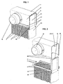
- FIG. 2 in conjunction with FIGS. 9 and 10 , shows the contour cutout 40 is formed in the exemplary embodiment so that the two connecting longitudinal edges 5 slightly above the remaining connecting transverse edge 6 of the tube sheet 3 protrude.
- the protruding connecting longitudinal edges have the reference numeral 51 in FIGS. 2, 9 and 10.
- a graduation 50 whose size approximately corresponds to the sheet thickness of the collecting boxes 7 , or the sheet thickness of the longitudinal walls 8 , 9 , also belongs on both sides.
- the projecting connecting longitudinal edges 51 thus each receive a projection 20 between them and the edge 14 of the closure cap 11 .
- the connection between the connecting transverse edge 5 and the closure cap 11 as shown in FIG. 12, be formed without a flange. 13 and 14, however, show a flange 41 , wherein in Fig. 13, the flange is directed downward and in Fig. 14 upwards to create a solid and tight solder joint even with thinner tube sheets 3 .
- a cutout 16 is provided, into which a flap 17 has been bent on the transverse wall of the collecting box 7 in order to provide a provisional holding of the heat exchanger in the production phase.
- the partial longitudinal section shown in FIG. 11 runs exactly through the mentioned means 15 for fixing and shows the tab 17 in the already bent state.
- the assembly process of the heat exchanger is in the described embodiment as follows:
- the flat tubes 1 are alternately assembled with the corrugated fins 2 to the so-called rib-tube block.
- the side parts 10 are attached to the caps 11 .
- a tube plate 3 is raised at each end of the flat tubes 1 , after which the ends of the flat tubes 1 are inserted into the openings 4 of the tubesheets 3 .
- the collecting boxes 7 are placed on the tubesheets 3 , wherein the projections 20 are respectively inserted into the openings 30 .
- the headers 7 are thereby fixed in their longitudinal direction.
- a pressing of the connecting longitudinal edges 5 of the tube sheet 3 to the longitudinal walls 8 , 9 of the collecting tank 7 is achieved.
- the mentioned means 15 are used for fixing, which are preferably formed in the form of the tabs 17 also mentioned, which are bent into the cutout 16 at the edge 14 of the cap 11 .
- the heat exchanger is thus a self-contained unit that can be prepared for the soldering process.
- FIG. 7 differs from FIG. 8 in that FIG. 7 shows a section in the region of a flat tube 1 and FIG. 8 shows another section in the region of the projections 20 .
- FIGS. 5 and 6 also differ only because of the different cutting planes.
- a heat exchanging medium into the collecting box 7 occurs, for example in the positions shown in Figs. 1 and 2 nozzles 70, and distributed to the flat tubes 1 to pass through to it.
- An identical or similar collection box 7 is located on the one side not shown (in the longitudinal direction of the flat tubes) of the heat exchanger and another not shown nozzle is arranged either on the shown or not shown collection box 7 to dissipate the heat exchanging medium. Cooling air flows through the corrugated fins 2 and is in heat exchanging relationship with the mentioned medium.
- only one side member 10 is shown, it being understood that a second side member is present on the second side not shown (transverse to the flat tubes) that is identical at least with respect to the features described herein.
- the closure caps 11 are formed as individual parts, as has also been provided in the non-prepublished application. Even with such heat exchangers, a contour cutout 40 is provided in the connecting transverse edges 6 of the tubesheets 3 . Further, at the edges of the longitudinal walls 8 , 9 of the manifolds 7 projections 20 are provided, which are inserted into corresponding openings 30 in the tube sheets 3 . The mentioned openings 30 are not recognizable in FIG. 15, for which reason reference is made to FIG. 9 in this regard.
- the fixing means 15 which are required in this embodiment rather than in the first embodiment, consist of clips formed on the edge 14 of the closure cap 11 .
Abstract
Description
Die Erfindung betrifft einen Wärmeaustauscher, insbesondere für Kraftfahrzeuge, dessen Komponenten aus Flachrohren, aus Wellrippen, aus Rohrböden mit Öffnungen zur Aufnahme der Enden der Flachrohre und mit Verbindungslängs-und Verbindungsquerrändern, sowie mit vier Eckbereichen, bestehen, und aus Sammelkästen mit zwei Längswänden zur Verbindung mit den Verbindungslängsrändern, aus Seitenteilen mit Verschlusskappen, zum Verschluss der seitlichen Öffnungen der Sammelkästen, wobei die Verschlusskappen einen Rand aufweisen und wobei sämtliche Teile aus Aluminium hergestellt sind, das zweckmäßig mit Lot beschichtet ist, zur metallischen Verbindung mittels eines Lötprozesses.The invention relates to a heat exchanger, in particular for motor vehicles, its components made of flat tubes, corrugated fins, tube sheets with Openings for receiving the ends of the flat tubes and with connecting longitudinal and Crossing edges, as well as with four corners, exist, and off Collection boxes with two longitudinal walls for connection to the Connecting longitudinal edges, from side parts with caps, to the closure the lateral openings of the collecting boxes, wherein the closure caps a Have edge and wherein all parts are made of aluminum, the is suitably coated with solder, for metallic connection by means of a Soldering process.
Dieser Wärmeübertrager wurde am 22.07.03 beim DPMA angemeldet und erhielt das Aktenzeichen DE 103 33 150.6.This heat exchanger was registered with the DPMA on July 22, 2003 and received the file number DE 103 33 150.6.
Ein anderer nicht vorveröffentlichter Wärmeaustauscher wurde am 17.08.02 beim DPMA angemeldet und erhielt das Aktenzeichen DE 102 37 769.3.Another not previously published heat exchanger was on 17.08.02 at DPMA filed and received the file number DE 102 37 769.3.
Die Aufgabe der Erfindung besteht in der Weiterentwicklung dieses Standes der Technik. Insbesondere soll ein Wärmeaustauscher vorgeschlagen werden, dessen Herstellbarkeit, insbesondere hinsichtlich der Schaffung dichter und fester Lötverbindungen, weiter vereinfacht bzw. verbessert werden soll.The object of the invention consists in the development of this state of the Technology. In particular, a heat exchanger is to be proposed, whose Manufacturability, in particular with regard to the creation of denser and stronger Soldered, further simplified or improved.
Die erfindungsgemäße Lösung erfolgt bei dem im Oberbegriff des Patentanspruchs 1
beschriebenen Wärmeaustauscher durch dessen kennzeichnende Merkmale.The solution according to the invention is carried out in the preamble of
Weil die Längswände der Sammelkästen zwischen den Verbindungslängsrändern der Rohrböden angeordnet sind, wobei Vorsprünge an den Längswänden vorgesehen sind, die in korrespondierenden Öffnungen in den Rohrböden stecken, und weil die Verbindungsquerränder der Rohrböden einen Kontur - Ausschnitt aufweisen, um mit den Verschlusskappen eine dichte und feste Lötverbindung zu bilden, wurde eine weitere Verbesserung der Herstellbarkeit erreicht, wobei damit insbesondere hochwertige löttechnische Verbindungen gemeint sind. Die Vorsprünge in den Öffnungen bewirken, dass die Längswände der Sammelkästen beim Einsetzen ihrer Vorsprünge in die Öffnungen im Rohrboden dicht an die Verbindungslängsränder des Rohrbodens gepresst werden. Der Kontur - Ausschnitt in den Verbindungsquerrändern der Rohrböden führt zu dichten Lötverbindungen in den Eckbereichen der Rohrböden. Die Ausbildung von scharfkantigen Eckbereichen, wie sie in der nicht vorveröffentlichten Anmeldung vorgesehen ist, wird mit dieser vorgeschlagenen Ausbildung überflüssig bzw. umgangen. Der Kontur - Ausschnitt kann mit einer flanschartigen Abkantung weitergebildet werden, um die Verbindungsfläche mit der Verschlusskappe zu erhöhen. Diese Maßnahme kann insbesondere vorgesehen werden, wenn die Blechdicke des Rohrbodens reduziert werden soll.Because the longitudinal walls of the headers between the connecting longitudinal edges the tube sheets are arranged, with projections on the longitudinal walls are provided, which plug into corresponding openings in the tube sheets, and because the connecting transverse edges of the tubesheets have a contour cutout To use the caps with a tight and strong solder joint Forming, a further improvement in manufacturability was achieved, with it in particular high-quality soldering connections are meant. The projections in the openings cause the longitudinal walls of the collecting tanks when Inserting their projections in the openings in the tube sheet close to the Connecting longitudinal edges of the tubesheet are pressed. The contour - cutout in the connecting transverse edges of the tube sheets leads to dense solder joints in the corner areas of the tubesheets. The formation of sharp-edged corner areas, as provided in the non-prepublished application is with this proposed training superfluous or circumvented. The contour - cutout Can be further developed with a flange-like fold to the Increase connection area with the cap. This measure can be provided in particular when the sheet thickness of the tube sheet is reduced shall be.
Weitere erfindungsgemäße Weiterbildungen sind in den Ansprüchen enthalten.Further developments according to the invention are contained in the claims.
Die Erfindung wird nachfolgend in Ausführungsbeispielen an Hand der beigefügten Zeichnungen beschrieben. Aus der Beschreibung ergeben sich weitere Merkmale und Vorteile.The invention will be described below in embodiments with reference to the attached Drawings described. From the description, further features arise and benefits.
Die Abbildungen zeigen Folgendes:
- Fig. 1
- Perspektivische Teilansicht eines erfindungsgemäßen Wärmeaustauschers;
- Fig. 2
- Wie Fig. 1 aber vor dem Anfügen des Sammelkastens;
- Fig. 3
- Teil - Seitenansicht des Wärmeaustauschers;
- Fig. 4 - 8
- Schnitte A - A bis E - E aus Fig. 3;
- Fig. 9
- Draufsicht auf einen Teil des Rohrbodens;
- Fig. 10
- Perspektivische Ansicht eines Rohrbodenteils;
- Fig. 11
- Schnitt F-F aus Fig. 6;
- Fig. 12 - 14
- Einzelheit aus Fig. 11 in Varianten;
- Fig. 15
- Ansicht eines zweiten Ausführungsbeispiels;
- Fig. 1
- Perspective partial view of a heat exchanger according to the invention;
- Fig. 2
- As shown in Figure 1 but before attaching the header tank.
- Fig. 3
- Part - side view of the heat exchanger;
- Fig. 4-8
- Sections A - A to E - E of Fig. 3;
- Fig. 9
- Top view of a part of the tube sheet;
- Fig. 10
- Perspective view of a tube bottom part;
- Fig. 11
- Section FF of Fig. 6;
- Fig. 12 - 14
- Detail of Figure 11 in variants.
- Fig. 15
- View of a second embodiment;
In den Figuren ist ein Wärmeaustauscher für Kraftfahrzeuge abgebildet, dessen
Komponenten aus Flachrohren 1, aus Wellrippen 2, aus Rohrböden 3 mit Öffnungen
4 zur Aufnahme der Enden der Flachrohre 1 und mit Verbindungslängs - und
Verbindungsquerrändern 5, 6, die vier Eckbereiche bilden, bestehen. Ferner besteht
der Wärmeaustauscher aus Sammelkästen 7 mit zwei Längswänden 8, 9 zur
Verbindung mit den Verbindungslängsrändern 5 und aus Seitenteilen 10 mit
Verschlusskappen 11, zum Verschluss der seitlichen Öffnungen der Sammelkästen
7, wobei die Verschlusskappen 11 einen abgekanteten Rand 14 aufweisen.
Außerdem sind im gezeigten Ausführungsbeispiel Mittel 15 zum Fixieren des
Wärmeaustauschers am Rand des Sammelkastens 6 und am Rand 14 der
Verschlusskappe 11 angeordnet, die zusammenwirken. Sämtliche erwähnten Teile
des Wärmeaustauschers sind aus Aluminiumblech hergestellt, das zweckmäßig mit
Lot beschichtet ist, zur metallischen Verbindung mittels eines Lötprozesses. In the figures, a heat exchanger for motor vehicles is shown, the components of
Die Längswände 8, 9 der Sammelkästen 7 sind zwischen den
Verbindungslängsrändern 5 der Rohrböden 3 angeordnet, wobei Vorsprünge 20 an
den Längswänden 8, 9 vorgesehen sind, die in korrespondierenden Öffnungen 30 in
den Rohrböden 3 stecken. Die Verbindungsquerränder 6 der Rohrböden 3 weisen
einen Kontur - Ausschnitt 40 auf, der mit den Verschlusskappen 11 eine dichte und
feste Lötverbindung bildet. Die Vorsprünge 20 haben eine leicht konische Form,
sodass eine gewisse Führung in die Öffnungen 30 hinein gewährleistet ist und dass
auch gleichzeitig sichergestellt wird, dass die Vorsprünge 20 eng am Rand der
Öffnungen 30 anliegen. Die Vorsprünge 20 und die Öffnungen 30 sind in
zweckmäßigen Abständen angeordnet, um ihre Funktion erfüllen zu können. Da in
den Bereichen rund um die Öffnungen 30 herum außerdem ausreichend Lotmaterial
zur Verfügung steht, wird eine dichte Lötverbindung der Vorsprünge 20 in den
Öffnungen 30 erwartet und gleichzeitig eine hohe Prozesssicherheit gewährleistet.
Die Öffnungen 30 im Rohrboden 3 sind vorzugsweise zwischen den Öffnungen 4 für
die Flachrohrenden angeordnet, damit eine maximale Tiefe des Rohr - Rippen -
Blocks gewährleistet ist. Sie befinden sich ferner vorzugsweise unmittelbar am
Verbindungslängsrand 5.The
Der Kontur-Ausschnitt 40 der Verbindungsquerränder 6 ist zwischen den
Verbindungslängsrändern 5 vorgesehen. Der Kontur-Ausschnitt 40 entspricht etwa
der Kontor der Verschlusskappe 11, damit eine feste und dichte Lötverbindung erzielt
wird. Die Kontur des Ausschnitts hängt somit von der gewählten Kontur der
Verschlusskappe 11 ab. Wie insbesondere die Fig. 2, in Verbindung mit den Fig. 9
und 10, zeigt, ist der Kontur-Ausschnitt 40 im Ausführungsbeispiel so ausgebildet,
dass die beiden Verbindungslängsränder 5 etwas über den restlichen
Verbindungsquerrand 6 des Rohrbodens 3 ragen. Die überragenden
Verbindungslängsränder besitzen in den Fig. 2, 9 und 10 das Bezugszeichen 51.
Zum Kontur - Ausschnitt 40 gehört im Ausführungsbeispiel ferner beidseitig je eine
Abstufung 50, deren Größe etwa der Blechdicke der Sammelkästen 7, bzw. der
Blechdicke der Längswände 8, 9 entspricht. Die überstehenden
Verbindungslängsränder 51 nehmen somit je einen Vorsprung 20 zwischen sich und
dem Rand 14 des Verschlusskappe 11 auf. Bei Rohrböden 3, die eine etwas größere
Blechdicke besitzen, kann die Verbindung zwischen deren Verbindungsquerrand 5
und der Verschlusskappe 11, wie in der Fig. 12 gezeigt, ohne Flansch ausgebildet
sein. Die Fig. 13 und 14 hingegen zeigen einen Flansch 41, wobei in der Fig. 13 der
Flansch nach unten gerichtet ist und in der Fig. 14 nach oben, um auch bei dünneren
Rohrböden 3 eine feste und dichte Lötverbindung zu schaffen.The
Am Rand 14 der Verschlusskappe 11 ist ein Ausschnitt 16 vorgesehen, in den eine
Lasche 17 an der Querwand des Sammelkastens 7 hineingebogen wurde, um eine
provisorische Halterung des Wärmeaustauschers in der Herstellungsphase zu
schaffen. Der in Fig. 11 dargestellte Teil - Längsschnitt verläuft genau durch die
erwähnten Mittel zum Fixieren 15 und zeigt die Lasche 17 im bereits umgebogenen
Zustand.At the
Der Montageprozess des Wärmeaustauschers ist in dem beschriebenen
Ausführungsbeispiel folgendermaßen: Die Flachrohre 1 werden abwechselnd mit den
Wellrippen 2 zum sogenannten Rippen - Rohr - Block zusammengesetzt. Danach
werden die Seitenteile 10 mit den Verschlusskappen 11 angesetzt. Anschließend
wird an beiden Enden der Flachrohre 1 je ein Rohrboden 3 aufgezogen, wonach die
Enden der Flachrohre 1 in den Öffnungen 4 der Rohrböden 3 stecken. Schließlich
werden die Sammelkästen 7 auf die Rohrböden 3 gesetzt, wobei die Vorsprünge 20
jeweils in die Öffnungen 30 eingeschoben werden. Die Sammelkästen 7 sind
dadurch in ihrer Längsrichtung festgelegt. Gleichzeitig wird damit ein Anpressen der
Verbindungslängsränder 5 des Rohrbodens 3 an die Längswände 8, 9 des
Sammelkastens 7 erreicht. Danach kommen die erwähnten Mittel 15 zum Fixieren
zum Einsatz, die vorzugsweise in Form der ebenfalls erwähnten Laschen 17
ausgebildet sind, die in den Ausschnitt 16 am Rand 14 der Verschlusskappe 11
gebogen werden. Der Wärmeaustauscher ist somit eine sich selbst haltende Einheit,
die für den Lötprozess vorbereitet werden kann.The assembly process of the heat exchanger is in the described embodiment as follows: The
Die Fig. 7 unterscheidet sich von der Fig. 8 dadurch, dass die Fig. 7 einen Schnitt im
Bereich eines Flachrohres 1 zeigt und die Fig. 8 einen anderen Schnitt im Bereich
der Vorsprünge 20. Die Fig. 5 und 6 unterscheiden sich ebenfalls nur wegen der
unterschiedlichen Schnittebenen.FIG. 7 differs from FIG. 8 in that FIG. 7 shows a section in the region of a
In den Figuren wurde kein kompletter Wärmeaustauscher abgebildet, weil der
Fachmann, an den sich eine Anmeldung gewöhnlich wendet, die nicht gezeigten
Teile ohne weiteres zu einem vollständigen Wärmeaustauscher ergänzen wird. Ein
wärmetauschendes Medium tritt beispielsweise in den in den Fig. 1 und 2 gezeigten
Stutzen 70 in den Sammelkasten 7 ein und verteilt sich auf die Flachrohre 1, um
diese zu durchströmen. Ein identischer oder ähnlicher Sammelkasten 7 befindet sich
auf der einen nicht gezeigten Seite (in Längsrichtung der Flachrohre) des
Wärmeaustauschers und ein weiterer nicht gezeigter Stutzen ist entweder am
gezeigten oder am nicht gezeigten Sammelkasten 7 angeordnet, um das
wärmetauschende Medium abzuführen. Kühlluft strömt durch die Wellrippen 2 und
steht mit dem erwähnten Medium in wärmetauschender Beziehung. Ferner ist
lediglich ein Seitenteil 10 gezeigt, wobei sich versteht, dass ein zweites Seitenteil auf
der zweiten nicht gezeigten Seite (in Querrichtung zu den Flachrohren) vorhanden
ist, das wenigstens bezüglich der hier beschriebenen Merkmale identisch ist.No complete heat exchanger has been illustrated in the figures, because those skilled in the art, to whom an application will commonly refer, will readily supplement the parts not shown to a complete heat exchanger. A heat exchanging medium into the
Im Ausführungsbeispiel aus der Fig. 15 sind die Verschlusskappen 11 als Einzelteile
ausgebildet, wie es auch in der nicht vorveröffentlichten Anmeldung vorgesehen
worden ist. Auch bei solchen Wärmeaustauschern wird in den
Verbindungsquerrändern 6 der Rohrböden 3 ein Kontur - Ausschnitt 40 vorgesehen.
Ferner sind an den Rändern der Längswände 8, 9 der Sammelkästen 7 Vorsprünge
20 vorhanden, die in korrespondierende Öffnungen 30 in den Rohrböden 3
eingeführt werden. Die erwähnten Öffnungen 30 sind in der Fig. 15 nicht erkennbar,
weswegen diesbezüglich auf die Fig. 9 verwiesen wird. Die Mittel zum Fixieren 15,
die in diesem Ausführungsbeispiel eher erforderlich sind als in dem ersten
Ausführungsbeispiel, bestehen aus an dem Rand 14 der Verschlusskappe 11
ausgebildeten Klammern.In the embodiment of FIG. 15, the closure caps 11 are formed as individual parts, as has also been provided in the non-prepublished application. Even with such heat exchangers, a
Claims (7)
und aus Sammelkästen (7) mit zwei Längswänden (8, 9) zur Verbindung mit den Verbindungslängsrändern (5), aus Seitenteilen (10) mit Verschlusskappen (11) oder mit einzelnen Verschlusskappen (11), zum Verschluss der seitlichen Öffnungen der Sammelkästen (7), wobei die Verschlusskappen (11) einen Rand (14) aufweisen, und aus - wahlweise mit oder ohne - Mittel zum Fixieren (15) des Wärmeaustauschers, die an den seitlichen Öffnungen der Sammelkästen (7) und / oder am Rand (14) der Verschlusskappen (11) angeordnet sind und zusammenwirken, bestehen, und wobei sämtliche Teile aus Aluminium hergestellt sind, das zweckmäßig mit Lot beschichtet ist, zur metallischen Verbindung mittels eines Lötprozesses,
gekennzeichnet, durch die Ränder der Längswände (8, 9) der Sammelkästen (7), die zwischen den Verbindungslängsrändern (5) der Rohrböden (3) angeordnet sind, wobei Vorsprünge (20) an den Rändern der Längswände (8, 9) vorgesehen sind, die in korrespondierenden Öffnungen (30) in den Rohrböden (3) stecken,
und durch die Verbindungsquerränder (6) der Rohrböden (3), die einen Kontur - Ausschnitt (40) aufweisen, um mit den Verschlusskappen (11) eine dichte und feste Lötverbindung zu bilden.Heat exchangers, in particular for motor vehicles, whose components consist of flat tubes (1), corrugated fins (2), tubesheets (3) with openings (4) for receiving the ends of the flat tubes (1) and with connecting longitudinal and connecting transverse edges (5, 6) that make up four corner areas,
and from collecting boxes (7) with two longitudinal walls (8, 9) for connection to the connecting longitudinal edges (5), from side parts (10) with sealing caps (11) or with individual sealing caps (11), for closing the lateral openings of the collecting boxes (7 ), wherein the closure caps (11) have an edge (14), and - optionally with or without - means for fixing (15) of the heat exchanger, which at the lateral openings of the collecting boxes (7) and / or at the edge (14) the closure caps (11) are arranged and cooperate, and wherein all the parts are made of aluminum, suitably coated with solder, for the metallic connection by means of a soldering process,
characterized by the edges of the longitudinal walls (8, 9) of the collecting boxes (7), which are arranged between the connecting longitudinal edges (5) of the tubesheets (3), wherein projections (20) at the edges of the longitudinal walls (8, 9) are provided which are stuck in corresponding openings (30) in the tubesheets (3),
and through the connecting transverse edges (6) of the tubesheets (3), which have a contour cutout (40) in order to form a tight and firm soldered connection with the sealing caps (11).
Applications Claiming Priority (2)
| Application Number | Priority Date | Filing Date | Title |
|---|---|---|---|
| DE10347180A DE10347180A1 (en) | 2003-10-10 | 2003-10-10 | Heat exchangers, in particular for motor vehicles |
| DE10347180 | 2003-10-10 |
Publications (2)
| Publication Number | Publication Date |
|---|---|
| EP1522814A2 true EP1522814A2 (en) | 2005-04-13 |
| EP1522814A3 EP1522814A3 (en) | 2012-12-12 |
Family
ID=34306360
Family Applications (1)
| Application Number | Title | Priority Date | Filing Date |
|---|---|---|---|
| EP04021988A Withdrawn EP1522814A3 (en) | 2003-10-10 | 2004-09-16 | Heat exchanger, more particularly for automotive vehicle |
Country Status (3)
| Country | Link |
|---|---|
| US (1) | US7032656B2 (en) |
| EP (1) | EP1522814A3 (en) |
| DE (1) | DE10347180A1 (en) |
Cited By (5)
| Publication number | Priority date | Publication date | Assignee | Title |
|---|---|---|---|---|
| FR2902506A1 (en) * | 2006-06-19 | 2007-12-21 | Valeo Systemes Thermiques | Heat exchanger e.g. charge air cooler, for motor vehicle, has end crosspieces i.e. flanges, extending between manifolds and comprising folded tabs with ends supported on lateral faces of tubes |
| EP1923654A1 (en) * | 2006-11-18 | 2008-05-21 | Modine Manufacturing Company | Heat exchanger |
| EP1923653A1 (en) * | 2006-11-14 | 2008-05-21 | Modine Manufacturing Company | Heat exchanger |
| FR3056724A1 (en) * | 2016-09-28 | 2018-03-30 | Valeo Systemes Thermiques | THERMAL EXCHANGER, IN PARTICULAR FOR MOTOR VEHICLE |
| EP3916338A1 (en) * | 2020-05-26 | 2021-12-01 | Valeo Systemes Thermiques | A heat exchanger |
Families Citing this family (21)
| Publication number | Priority date | Publication date | Assignee | Title |
|---|---|---|---|---|
| JP2008506915A (en) * | 2004-07-16 | 2008-03-06 | ベール ゲーエムベーハー ウント コー カーゲー | Heat transfer body, case for containing fluid for heat transfer body and method for forming this type of case |
| US20060113069A1 (en) * | 2004-11-29 | 2006-06-01 | Denso Corporation | Heat exchanger |
| DE102005013922A1 (en) * | 2005-03-26 | 2006-09-28 | Modine Manufacturing Co., Racine | Heat exchanger e.g. intercooler, for motor vehicle, has frames provided at ends of stack of heat exchanging plates, where region of plates between holes is formed on side of flow path as heat exchanging region or as open channel section |
| US20080223562A1 (en) * | 2005-09-12 | 2008-09-18 | Viorel Braic | Heat Exchanger, in Particular Charge-Air Cooler or Exhaust Gas Cooler for an Internal Combustion Engine of a Motor Vehicle |
| DE102006058096A1 (en) * | 2006-12-09 | 2008-06-12 | Modine Manufacturing Co., Racine | Heat exchanger for use in motor vehicle, has flat tubes for providing flow path for fluid, and elastically deformable side part with integrally formed caps for closing openings in tanks, where fin is supported between tubes |
| US20080156455A1 (en) * | 2006-12-14 | 2008-07-03 | Powers Michael V | Heat exchanger manifolds with retention tabs |
| DE102008013134A1 (en) * | 2008-03-07 | 2009-09-10 | Audi Ag | A heat exchange device and method of manufacturing a heat exchange element for a heat exchange device |
| US20100108303A1 (en) * | 2007-04-05 | 2010-05-06 | Dana Canada Corporation | Heat exchanger construction |
| CN101226037A (en) * | 2008-01-30 | 2008-07-23 | 无锡优萌汽车部件制造有限公司 | Stitching structure for main tablet and side plate of novel vehicle warm air water chamber |
| FR2933175B1 (en) * | 2008-06-26 | 2014-10-24 | Valeo Systemes Thermiques | HEAT EXCHANGER HAVING A HEAT EXCHANGE BEAM AND A HOUSING |
| FR2933176B1 (en) * | 2008-06-26 | 2017-12-15 | Valeo Systemes Thermiques Branche Thermique Moteur | HEAT EXCHANGER HAVING A HEAT EXCHANGE BEAM AND A HOUSING |
| DE102009039569A1 (en) * | 2009-09-01 | 2011-03-03 | Behr Gmbh & Co. Kg | Gas cooler for an internal combustion engine |
| DE102009056509A1 (en) * | 2009-12-02 | 2011-06-09 | Behr Industry Gmbh & Co. Kg | Heat exchanger with form-fitting fixed collector box |
| DE102010039772A1 (en) * | 2010-08-25 | 2012-04-26 | Behr Gmbh & Co. Kg | Heat exchanger for use in internal combustion engine, has ribs and pipe provided with block that is arranged between two containers |
| DE102010040638A1 (en) * | 2010-09-13 | 2012-03-15 | Behr Gmbh & Co. Kg | Box e.g. aluminum sheet box, for receiving of fluid i.e. coolant, for heat exchanger in motor car, has connection plates bent such that plates are planar-connected to side walls, and/or base and/or cover connected by solder connection part |
| DE102011077838A1 (en) | 2011-06-20 | 2012-12-20 | Behr Gmbh & Co. Kg | Heat exchanger and method for producing a heat exchanger |
| DE102012020882B4 (en) * | 2012-10-24 | 2014-08-28 | Audi Ag | Method for producing a heat exchanger for a motor vehicle and heat exchanger for a motor vehicle |
| US20140284038A1 (en) * | 2013-03-21 | 2014-09-25 | Hamilton Sundstrand Corporation | Heat exchanger design and fabrication |
| DE102014206612A1 (en) * | 2014-04-04 | 2015-10-29 | Mahle International Gmbh | heat exchangers |
| DE102015010288A1 (en) | 2014-08-22 | 2016-02-25 | Modine Manufacturing Company | Heat exchanger, heat exchanger tank and method of making same |
| DE102017109708A1 (en) * | 2017-05-05 | 2018-11-08 | Benteler Automobiltechnik Gmbh | Cooling arrangement, fluid collector for a cooling arrangement and method for producing a fluid collector |
Citations (2)
| Publication number | Priority date | Publication date | Assignee | Title |
|---|---|---|---|---|
| DE10237769A1 (en) | 2002-08-17 | 2004-02-26 | Modine Manufacturing Co., Racine | Heat exchangers and manufacturing processes |
| DE10333150A1 (en) | 2003-07-22 | 2005-02-17 | Modine Manufacturing Co., Racine | Heat exchangers for motor vehicles |
Family Cites Families (20)
| Publication number | Priority date | Publication date | Assignee | Title |
|---|---|---|---|---|
| US2899177A (en) * | 1959-08-11 | Method of making same | ||
| US2073778A (en) * | 1936-09-16 | 1937-03-16 | Modine Mfg Co | Radiator |
| US3275070A (en) * | 1963-04-09 | 1966-09-27 | Gen Motors Corp | Crossflow radiators |
| GB2098313A (en) * | 1981-05-09 | 1982-11-17 | Imi Radiators | Heat exchanger for automobiles |
| US5355941A (en) * | 1993-09-17 | 1994-10-18 | Ford Motor Company | Sealing apparatus for a heat exchanger manifold |
| SE503085C2 (en) * | 1995-01-25 | 1996-03-25 | Valeo Engine Cooling Ab | Heat exchanger tank with end pieces, method of making such a tank, and heat exchanger provided with such |
| DE19515530C2 (en) * | 1995-04-27 | 2001-11-15 | Valeo Klimatech Gmbh & Co Kg | Water box of a heat exchanger for motor vehicles |
| JPH08327281A (en) * | 1995-05-30 | 1996-12-13 | Sanden Corp | Header for heat exchanger |
| US5607012A (en) * | 1995-06-12 | 1997-03-04 | General Motors Corporation | Heat exchanger |
| JPH10170187A (en) * | 1996-12-03 | 1998-06-26 | Calsonic Corp | Tank for heat exchanger |
| DE19722098B4 (en) * | 1997-03-11 | 2007-01-18 | Behr Gmbh & Co. Kg | Heat exchanger for a motor vehicle |
| EP0864838B1 (en) * | 1997-03-11 | 2002-12-04 | Behr GmbH & Co. | Heat exchanger for automotive vehicle |
| DE19722097A1 (en) * | 1997-05-27 | 1998-12-03 | Behr Gmbh & Co | Heat exchanger and heat exchanger arrangement for a motor vehicle |
| JPH11142086A (en) * | 1997-11-06 | 1999-05-28 | Denso Corp | Heat-exchanger |
| JPH11148794A (en) * | 1997-11-14 | 1999-06-02 | Zexel:Kk | Heat exchanger |
| DE19819247A1 (en) * | 1998-04-29 | 1999-11-11 | Valeo Klimatech Gmbh & Co Kg | Vehicle heat exchanger and especially water/air heat exchanger or evaporator |
| JP4324890B2 (en) * | 1999-06-29 | 2009-09-02 | 株式会社ティラド | Manufacturing method of tank for heat exchanger and the tank |
| JP2002257493A (en) * | 2001-02-28 | 2002-09-11 | Toyo Radiator Co Ltd | Manufacturing method of heat exchanger made of aluminum |
| DE10132484A1 (en) * | 2001-07-05 | 2003-01-23 | Behr Gmbh & Co | Heat exchanger and method for its production |
| FR2835909B1 (en) * | 2002-02-12 | 2004-07-16 | Valeo Thermique Moteur Sa | COLLECTOR BOX FOR HEAT EXCHANGER, PARTICULARLY FOR A MOTOR VEHICLE |
-
2003
- 2003-10-10 DE DE10347180A patent/DE10347180A1/en not_active Withdrawn
-
2004
- 2004-09-16 EP EP04021988A patent/EP1522814A3/en not_active Withdrawn
- 2004-10-07 US US10/960,376 patent/US7032656B2/en not_active Expired - Fee Related
Patent Citations (2)
| Publication number | Priority date | Publication date | Assignee | Title |
|---|---|---|---|---|
| DE10237769A1 (en) | 2002-08-17 | 2004-02-26 | Modine Manufacturing Co., Racine | Heat exchangers and manufacturing processes |
| DE10333150A1 (en) | 2003-07-22 | 2005-02-17 | Modine Manufacturing Co., Racine | Heat exchangers for motor vehicles |
Cited By (7)
| Publication number | Priority date | Publication date | Assignee | Title |
|---|---|---|---|---|
| FR2902506A1 (en) * | 2006-06-19 | 2007-12-21 | Valeo Systemes Thermiques | Heat exchanger e.g. charge air cooler, for motor vehicle, has end crosspieces i.e. flanges, extending between manifolds and comprising folded tabs with ends supported on lateral faces of tubes |
| EP1923653A1 (en) * | 2006-11-14 | 2008-05-21 | Modine Manufacturing Company | Heat exchanger |
| EP1923654A1 (en) * | 2006-11-18 | 2008-05-21 | Modine Manufacturing Company | Heat exchanger |
| FR3056724A1 (en) * | 2016-09-28 | 2018-03-30 | Valeo Systemes Thermiques | THERMAL EXCHANGER, IN PARTICULAR FOR MOTOR VEHICLE |
| WO2018060623A3 (en) * | 2016-09-28 | 2018-05-17 | Valeo Systemes Thermiques | Heat exchanger, especially for a motor vehicle |
| EP3916338A1 (en) * | 2020-05-26 | 2021-12-01 | Valeo Systemes Thermiques | A heat exchanger |
| WO2021239330A1 (en) * | 2020-05-26 | 2021-12-02 | Valeo Systemes Thermiques | A heat exchanger |
Also Published As
| Publication number | Publication date |
|---|---|
| US7032656B2 (en) | 2006-04-25 |
| DE10347180A1 (en) | 2005-05-12 |
| US20050077035A1 (en) | 2005-04-14 |
| EP1522814A3 (en) | 2012-12-12 |
Similar Documents
| Publication | Publication Date | Title |
|---|---|---|
| EP1522814A2 (en) | Heat exchanger, more particularly for automotive vehicle | |
| EP1703243B1 (en) | Heat exchanger with tubes and fins and process to manufacture it | |
| EP0379701B1 (en) | Heat exchanger | |
| DE19752139B4 (en) | Heat exchanger for a motor vehicle | |
| EP0881447B1 (en) | Heat exchanger and heat exchanging apparatus for vehicle | |
| EP1281923B1 (en) | Flat tube for heat exchanger and process of fabricating the same | |
| EP0864838B1 (en) | Heat exchanger for automotive vehicle | |
| DE3720483A1 (en) | Heat exchanger | |
| DE19722098B4 (en) | Heat exchanger for a motor vehicle | |
| EP0864840B1 (en) | Heat exchanger for automotive vehicle | |
| EP1707911A1 (en) | Heat exchanger, for example charged-air cooler and manufacturing process. | |
| EP0672882A1 (en) | Heat exchanger fin | |
| DE4305060C2 (en) | Soldered heat exchanger, especially evaporator | |
| DE4026988A1 (en) | Heat exchanger in vehicle - comprises assembly of flat pipes and corrugated rib units | |
| EP1376043B1 (en) | Heat exchanger with diffuser | |
| DE3834822A1 (en) | Heat exchanger | |
| EP1500892A2 (en) | Heat exchanger for vehicles | |
| EP1391676A2 (en) | Heat exchanger and method for manufacturing same | |
| DE19961199B4 (en) | The heat exchanger | |
| EP1148312B1 (en) | Radiator for vehicles | |
| EP1384968B1 (en) | Heat exchanger and associated process of fabricating | |
| DE4120869A1 (en) | Finned tube vehicle radiator - has tube openings in end plates widened to also secure side section lugs | |
| DE2952724C2 (en) | Heat exchanger | |
| DE3047411C2 (en) | Heat exchanger | |
| EP1503165B1 (en) | Vehicles cooler |
Legal Events
| Date | Code | Title | Description |
|---|---|---|---|
| PUAI | Public reference made under article 153(3) epc to a published international application that has entered the european phase |
Free format text: ORIGINAL CODE: 0009012 |
|
| AK | Designated contracting states |
Kind code of ref document: A2 Designated state(s): AT BE BG CH CY CZ DE DK EE ES FI FR GB GR HU IE IT LI LU MC NL PL PT RO SE SI SK TR |
|
| AX | Request for extension of the european patent |
Extension state: AL HR LT LV MK |
|
| PUAL | Search report despatched |
Free format text: ORIGINAL CODE: 0009013 |
|
| AK | Designated contracting states |
Kind code of ref document: A3 Designated state(s): AT BE BG CH CY CZ DE DK EE ES FI FR GB GR HU IE IT LI LU MC NL PL PT RO SE SI SK TR |
|
| AX | Request for extension of the european patent |
Extension state: AL HR LT LV MK |
|
| RIC1 | Information provided on ipc code assigned before grant |
Ipc: F28F 9/00 20060101AFI20121106BHEP Ipc: F28D 1/053 20060101ALI20121106BHEP |
|
| STAA | Information on the status of an ep patent application or granted ep patent |
Free format text: STATUS: THE APPLICATION HAS BEEN WITHDRAWN |
|
| 18W | Application withdrawn |
Effective date: 20121207 |