EP1521320B1 - Separator für Brennstoffzelle - Google Patents
Separator für Brennstoffzelle Download PDFInfo
- Publication number
- EP1521320B1 EP1521320B1 EP04023238.1A EP04023238A EP1521320B1 EP 1521320 B1 EP1521320 B1 EP 1521320B1 EP 04023238 A EP04023238 A EP 04023238A EP 1521320 B1 EP1521320 B1 EP 1521320B1
- Authority
- EP
- European Patent Office
- Prior art keywords
- separator
- fuel cell
- thermosetting resin
- filler
- weight
- Prior art date
- Legal status (The legal status is an assumption and is not a legal conclusion. Google has not performed a legal analysis and makes no representation as to the accuracy of the status listed.)
- Expired - Fee Related
Links
Images


Classifications
-
- H—ELECTRICITY
- H01—ELECTRIC ELEMENTS
- H01M—PROCESSES OR MEANS, e.g. BATTERIES, FOR THE DIRECT CONVERSION OF CHEMICAL ENERGY INTO ELECTRICAL ENERGY
- H01M8/00—Fuel cells; Manufacture thereof
- H01M8/02—Details
- H01M8/0202—Collectors; Separators, e.g. bipolar separators; Interconnectors
- H01M8/0204—Non-porous and characterised by the material
- H01M8/0223—Composites
- H01M8/0226—Composites in the form of mixtures
-
- H—ELECTRICITY
- H01—ELECTRIC ELEMENTS
- H01M—PROCESSES OR MEANS, e.g. BATTERIES, FOR THE DIRECT CONVERSION OF CHEMICAL ENERGY INTO ELECTRICAL ENERGY
- H01M8/00—Fuel cells; Manufacture thereof
- H01M8/02—Details
- H01M8/0202—Collectors; Separators, e.g. bipolar separators; Interconnectors
- H01M8/0204—Non-porous and characterised by the material
- H01M8/0221—Organic resins; Organic polymers
-
- H—ELECTRICITY
- H01—ELECTRIC ELEMENTS
- H01M—PROCESSES OR MEANS, e.g. BATTERIES, FOR THE DIRECT CONVERSION OF CHEMICAL ENERGY INTO ELECTRICAL ENERGY
- H01M8/00—Fuel cells; Manufacture thereof
- H01M8/02—Details
- H01M8/0202—Collectors; Separators, e.g. bipolar separators; Interconnectors
- H01M8/0204—Non-porous and characterised by the material
- H01M8/0213—Gas-impermeable carbon-containing materials
-
- H—ELECTRICITY
- H01—ELECTRIC ELEMENTS
- H01M—PROCESSES OR MEANS, e.g. BATTERIES, FOR THE DIRECT CONVERSION OF CHEMICAL ENERGY INTO ELECTRICAL ENERGY
- H01M8/00—Fuel cells; Manufacture thereof
- H01M8/02—Details
- H01M8/0202—Collectors; Separators, e.g. bipolar separators; Interconnectors
- H01M8/0204—Non-porous and characterised by the material
- H01M8/0215—Glass; Ceramic materials
-
- Y—GENERAL TAGGING OF NEW TECHNOLOGICAL DEVELOPMENTS; GENERAL TAGGING OF CROSS-SECTIONAL TECHNOLOGIES SPANNING OVER SEVERAL SECTIONS OF THE IPC; TECHNICAL SUBJECTS COVERED BY FORMER USPC CROSS-REFERENCE ART COLLECTIONS [XRACs] AND DIGESTS
- Y02—TECHNOLOGIES OR APPLICATIONS FOR MITIGATION OR ADAPTATION AGAINST CLIMATE CHANGE
- Y02E—REDUCTION OF GREENHOUSE GAS [GHG] EMISSIONS, RELATED TO ENERGY GENERATION, TRANSMISSION OR DISTRIBUTION
- Y02E60/00—Enabling technologies; Technologies with a potential or indirect contribution to GHG emissions mitigation
- Y02E60/30—Hydrogen technology
- Y02E60/50—Fuel cells
Definitions
- the present invention relates to a separator for fuel cell.
- a fuel cell has a structure comprising a stack of many unit cells each comprising electrode plates, an electrolyte film sandwiched therebetween, and a separator disposed on an outer side of these.
- Fig. 1 is a diagrammatic view illustrating the appearance of a general separator for fuel cell.
- This separator comprises a flat plate member 6 and partition walls 7 disposed on each side of the flat plate member 6 at a given interval.
- many such fuel-cell separators 5 are stacked in the direction of projection of the partition walls (upward/downward direction in the figure).
- This stacking forms a constitution in which a reactant gas (hydrogen or oxygen) is passed through channels 8 each formed by a pair of adjacent partition walls 7.
- the fuel-cell separator 5 is required to have excellent gas impermeability so as to prevent the two reactant gases from mixing with each other.
- the fuel-cell separator 5 is further required to have high electrical conductivity and excellent strength because unit cells are stacked.
- the warpage of fuel-cell separators not only makes stack assembly difficult but also results in insufficient contact between unit cells after assembly. As a result, contact electrical resistance becomes uneven, leading to a decrease in power generation performance. There are also cases where an offset load breaks the fuel-cell separators.
- Separators for fuel cells are generally obtained by a method in which a conductive resin composition comprising a thermosetting resin and, dispersed therein, ingredients such as a conductive filler, e.g., graphite, and a carbon fiber or the like for reinforcement is press-molded as a molding material into a give shape, since this method is advantageous in productivity. Because of this, in case where a molding material containing an ingredient insufficiently dispersed therein is used, this ingredient in the fuel-cell separator obtained is unevenly distributed and this causes local differences in thermal expansion coefficient, resulting in warpage or undulation and also in a local deficiency in strength.
- a conductive resin composition comprising a thermosetting resin and, dispersed therein, ingredients such as a conductive filler, e.g., graphite, and a carbon fiber or the like for reinforcement is press-molded as a molding material into a give shape, since this method is advantageous in productivity. Because of this, in case where a molding material containing an ingredient insufficiently
- the direction perpendicular to the thickness direction is referred to as the horizontal direction.
- the molding material is generally prepared by dry-mixing a thermosetting resin with compounding ingredients, the mixing operation unavoidably requires much time so as to heighten the dispersion of the compounding ingredients.
- Known techniques for diminishing warpage include a fuel-cell separator in which surfaces which come into contact with an electrode part have a lower resin content than surfaces which do not come into contact with an electrode part (see reference 1), and a fuel-cell separator in which at least part of the periphery or outer surfaces has been reinforced with a reinforcement comprising a metallic material, fiber-reinforced resin material, or the like (see reference 2).
- a specific resin and a specific conductive filler are used for diminishing the coefficient of thermal expansion.
- a fuel-cell separator which is obtained from a composition comprising graphite particles having a specific aspect ratio and a specific mean particle size, a phenolic novolak resin, and a carbon fiber and which has a difference in density between the partition walls and the grooves (see reference 3).
- thermosetting resin in place of the dry-mixing described above.
- a method which comprises adding compounding ingredients to a liquid thermosetting resin (initial polymer for a thermosetting resin) or to a solution of a thermosetting resin in a solvent and mixing all these ingredients together (see, for example, reference 4).
- thermosetting resin Since the liquid thermosetting resin has a high viscosity, the mixing thereof with compounding ingredients requires a considerably high torque and necessitates a large high-power mixing machine. In the case where a solution of a thermosetting resin in a solvent is used, it is necessary to separately conduct the step of removing the solvent and the step of treating the solvent removed, from the standpoint of environmental preservation. These steps lead to a cost increase.
- JP2001335695A describes a thermosettable resin molding material, which comprises 10 to 25 wt% of a thermosetting resin, 70 to 85 wt% of graphite and 0.1 to 3 wt% of spherical silica.
- JP2002155149A describes a carbonaceous powder molding material comprising carbonaceous powder and phenolic resin powder in a weight ratio of 95/5 to 80/20 and silica in an amount of 0.1 to 5 wt%.
- An object of the present invention which has been achieved under these circumstances, is to provide a high-performance separator for fuel cell which is far reduced in warpage as compared with the fuel-cell separators proposed so far, has excellent suitability for assembly, does not break, attains excellent tight contact between unit cells, and is free from unevenness in contact electrical resistance.
- the present inventors have made eager investigation to examine the problem. As a result, it has been found that the foregoing objects can be achieved by the following separator for fuel cell, forming material for fuel-cell separator and process for producing the fuel-cell separator. With this finding, the present invention is accomplished.
- the present invention is mainly directed to the following items:
- the separator for fuel cell of the invention is a molding of a given shape, such as that shown in Fig. 1 , formed from a forming material for fuel-cell separator, which is produced from a conductive resin composition.
- a forming material for fuel-cell separator which is produced from a conductive resin composition.
- forming material the forming material produced from the conductive resin composition simply referred to as "forming material”.
- This separator is characterized in that the difference between the thermal expansion coefficient as measured in the thickness direction and the thermal expansion coefficient as measured in the horizontal direction is 20 ⁇ 10 -6 K -1 or smaller.
- the shape of the separator and the forming material are not particularly limited as long as this requirement concerning a difference in thermal expansion coefficient is satisfied.
- the forming material of the invention preferably comprises powder, formed from the conductive resin composition, comprising a thermosetting resin and, a dimensionally anisotropic conductive filler, a spherical filler, and a carbon fiber each dispersed in the thermosetting resin.
- a dimensionally anisotropic conductive filler, a spherical filler, and a carbon fiber are preferably embedded in a thermosetting resin to form a particle of the powder, and such particles gather together to constitute the forming material.
- a dimensionally anisotropic conductive filler stands for a conductive filler having an aspect ratio of not less than 10.
- the conductive resin composition of the invention preferably comprises 20-60% by weight of a dimensionally anisotropic conductive filler, 20-40% by weight of a thermosetting resin, 15-30% by weight of a spherical filler, and 5-10% by weight of a carbon fiber based on the total weight of the conductive resin composition.
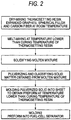
- Fig. 2 is a flow diagram showing an embodiment of the process of the invention for producing a separator for fuel cell.
- a powder of a thermosetting resin, a dimensionally anisotropic conductive filler, a spherical filler, and a carbon fiber are preferably first dry-mixed together at room temperature by means of a Henschel mixer, shaker, or the like to obtain a mixed powder.
- This dry-mixing need not be conducted over a prolonged period until the thermosetting resin becomes sufficiently evenly mixed with the compounding ingredients as in the related art method for obtaining a conductive resin composition through dry-mixing only. Consequently, a considerable reduction in mixing time can be attained.
- the powder mixture is melt-mixed at a temperature that the thermosetting resin does not cure completely, for example, about 100°C.
- a mixing machine such as a pressure kneader, Brabender, or a single- or twin-screw mixer.
- the thermosetting resin softens or fluidifies and infiltrates into interstices among the dimensionally anisotropic conductive filler, spherical filler, and carbon fiber.
- thermosetting resin dimensionally anisotropic conductive filler, spherical filler, and carbon fiber were not sufficiently evenly mixed in the dry-mixing, the dispersibility of the dimensionally anisotropic conductive filler, spherical filler, and carbon fiber in the thermosetting resin is enhanced by this melt-mixing.
- the molten mixture obtained is cooled and solidified.
- the cooling may be accomplished by allowing the molten mixture taken out of the mixing machine to stand at room temperature.
- the solid matter obtained comprises the thermosetting resin and the dimensionally anisotropic conductive filler, spherical filler, and carbon fiber each evenly dispersed therein.
- the solid matter obtained from the molten mixture is then pulverized to obtain the forming material of the invention.
- a known pulverizer such as, e.g., a Henschel mixer, mixer, or ball mill.
- the sizes of the individual particles constituting the forming material are not particularly limited, the mean particle size of the forming material is preferably 500 ⁇ m or smaller from the standpoints of ease of packing into molds and moldability.
- the individual particles comprise the thermosetting resin and the dimensionally anisotropic conductive filler, spherical filler, and carbon fiber each evenly dispersed therein as fine particles.
- the fuel-cell separator obtained from the forming material of the invention contains the dimensionally anisotropic conductive filler, spherical filler, and carbon fiber evenly dispersed therein as finer particles.
- This separator is hence excellent in various properties. Specifically, the difference between the thermal expansion coefficient of the separator as measured in the thickness direction and the thermal expansion coefficient thereof as measured in a direction perpendicular to the thickness direction (left/right direction on the page of Fig.
- the separator has excellent dimensional accuracy and shape stability with a warpage amount as small as 2 mm or less and has excellent mechanical properties with a flexural strength of 40 MPa or higher and a flexural modulus of 12 GPa or lower, as will be demonstrated in the Examples given later.
- the forming material of the invention When used for producing a separator for fuel cell, the forming material of the invention may be packed as it is into a mold for fuel-cell separators and press-molded at a temperature where the thermosetting resin cures completely, for example, 150-200°C.
- the powder obtained from the molten mixture is preferably packed into a mold and press-molded at a temperature where the thermosetting resin does not cure completely, for example, about 50-120°C, to obtain a sheet-form preform.
- the dimensionally anisotropic conductive filler, spherical filler, and carbon fiber are rearranged.
- the dimensionally anisotropic conductive filler, spherical filler, and carbon fiber in the preform obtained are distributed more evenly, and this further improves various properties of the fuel-cell separator to be obtained.
- a given number of sheets of the sheet-form preform are placed in a mold for fuel-cell separators, and press-molded at a mold temperature of, for example, 150-200°C (final molding) so that the thermosetting resin cures completely.
- a separator for fuel cell is obtained.
- a dimensionally anisotropic conductive filler, a spherical filler, and carbon fiber can be evenly dispersed in a thermosetting resin in preparing a conductive resin composition without the necessity of using a solvent as in the wet mixing heretofore in use.
- the thermosetting resin to be used can be a powdery one, an existing dry-mixing machine can be used as it is.
- the process of the invention is hence advantageous in cost.
- the dimensionally anisotropic conductive filler, spherical filler, and carbon fiber are highly evenly dispersed therein.
- the separator is hence excellent in dimensional stability and mechanical properties.
- thermosetting resins dimensionally anisotropic conductive fillers, spherical fillers, and carbon fiber for use in the process of the invention and the amounts of these ingredients to be incorporated are shown below as examples.
- thermosetting resin examples include epoxy resins, phenolic resins, furan resins, unsaturated polyester resins, and polyimide resins. These resins may be used alone or as a mixture of two or more thereof. From the standpoints of properties to be obtained, productivity, etc., it is preferred to use a mixture of an epoxy resin and a polyimide resin.
- epoxy resins as used here means a conception which includes all of structures formed by the reaction of a polyfunctional epoxy compound with a hardener and epoxy compound/hardener combinations which give such structures.
- an epoxy compound which has not undergone such a reaction and a structure yielded by the reaction are often referred to as an epoxy resin precursor and an epoxy compound, respectively.
- the amount of an epoxy resin is equal to the weight of a cured epoxy resin obtained therefrom.
- an epoxy resin precursor can be used any of various known compounds. Examples thereof include bifunctional epoxy compounds such as the bisphenol A diglycidyl ether type, bisphenol F diglycidyl ether type, bisphenol S diglycidyl ether type, bisphenol AD diglycidyl ether type, and resorcinol diglycidyl ether type; polyfunctional epoxy compounds such as the phenolic novolak type and cresol novolak type; and linear aliphatic epoxy compounds such as epoxidized soybean oil, alicyclic epoxy compounds, heterocyclic epoxy compounds, glycidyl ester epoxy compounds, and glycidylamine epoxy compounds.
- epoxy resin precursors usable in the invention should not be construed as being limited to these examples.
- the epoxy equivalent, molecular weight, number of epoxy groups, and the like of each of those compounds also are not particularly limited. However, when an epoxy resin precursor consisting mainly of an epoxy compound having an epoxy equivalent of about 400 or higher, especially about 700 or higher, is used, then a prolonged pot life can be obtained. In addition, since such compounds are solid at ordinary temperature, they are easy to handle in powder molding. It is also possible to use two or more epoxy compounds in combination. For example, an epoxy resin precursor having an epoxy equivalent of about 200 and giving a cured resin having a dense network structure is mixed with a precursor having an epoxy equivalent of about 900 and a long pot life. This mixture can be handled as a powder or as a liquid having a slightly long pot life.
- Those epoxy resin precursors react with a hardener to give cured epoxy resins.
- a hardener also, various known compounds can be used. Examples thereof include aliphatic, alicyclic, and aromatic polyamines such as dimethylenetriamine, triethylenetetramine, tetraethylenepentamine, menthenediamine, and isophoronediamine and carbonates of these polyamines; acid anhydrides such as phthalic anhydride, methyltetrahydrophthalic anhydride, and trimellitic anhydride; polyphenols such as phenolic novolak; polymercaptans; anionic polymerization catalysts such as tris (dimethylaminomethyl) phenol, imidazole, and ethylmethylimidazole; cationic polymerization catalysts such as BF 3 and complexes thereof; and latent hardeners which generate these compounds upon pyrolysis or photodecomposition.
- the hardener should not be construed as being limited to these examples. It is
- polyimides means a conception which includes all polymers having imide groups ((-CO-) 2 N-) in the molecule.
- examples thereof include thermoplastic polyimides such as poly(amide-imide)s and polyetherimides; non-thermoplastic polyimides such as (wholly) aromatic polyimides; and thermosetting polyimides such as bismaleimide-based polyimides, nadic acid-based polyimides, e.g., allylnadimide-based ones, and acetylene-based polyimides.
- the polyimides should not be construed as being limited to these examples. It is also possible to use two or more polyimides in combination. Especially preferred to these are thermosetting polyimides.
- Thermosetting polyimides have an advantage over thermoplastic polyimides and non-thermoplastic (aromatic) polyimides that they are easy to process.
- Thermosetting polyimides are highly satisfactory in high-temperature properties among various organic polymers, although inferior in the properties to non-thermoplastic polyimides.
- thermosetting polyimides develop almost no voids or cracks through curing. Thermosetting polyimides are hence suitable for use as a component of the conductive resin composition of the invention.
- the proportion of an epoxy resin and that of a polyimide resin are preferably 5-95% by weight and 95-5% by weight based on the whole amount of thermosetting resin, respectively. In case where the proportion of each resin is lower than 5% by weight, the advantage brought about by using these resins in combination is only slight.
- the ratio of the amount of an epoxy resin to that of a polyimide resin is more preferably from 95:5 to 30:70, even more preferably from 85:15 to 60:40.
- the amount of the thermosetting resin to be incorporated is preferably 20-40% by weight based on the whole amount of the conductive resin composition. In case where the amount thereof is smaller than 20% by weight, the material shows reduced flowability and is difficult to mold into a given shape. In addition, the function of the resin as a binder is lessened to pose problems, for example, that the resultant fuel-cell separator shows enhanced thickness memory and a desired thickness cannot be obtained. On the other hand, in case where the amount of the thermosetting resin incorporated exceeds 40% by weight, not only the resultant separator has insufficient strength and reduced electrical conductivity, but also the enhanced flowability of the composition poses problems, for example, that molding of the composition results in an increased amount of barrs and sticking to the mold. In view of these points, the amount of the thermosetting resin to be incorporated is more preferably 20-30% by weight.
- Examples of the dimensionally anisotropic conductive filler include expanded graphite, artificial graphite, and carbon black. Such dimensionally anisotropic conductive fillers can be used alone or as a mixture of two or more thereof. Preferred of these is expanded graphite from the standpoint of moldability and profitability. Expanded graphite is a graphite which is obtained, e.g., by treating flake graphite with concentrated sulfuric acid, and heating the treated to enlarge the interplanar spacing in the crystal structure of graphite, and is highly bulky.
- the expanded graphite to be used has a bulk specific gravity of preferably about 0.3 or lower, more preferably about 0.1 or lower, further more preferably about 0.05 or lower. Use of expanded graphite having such a bulk specific gravity gives a separator satisfactory especially in strength, electrical conductivity, and lubricity.
- the amount of the dimensionally anisotropic conductive filler to be incorporated is preferably 20-60% by weight based on the whole amount of the conductive resin composition. In case where the amount thereof is smaller than 20% by weight, satisfactory electrical conductivity cannot be obtained. In case where the amount thereof exceeds 60% by weight, problems concerning strength or molding operation arise. In view of these, the amount of the dimensionally anisotropic conductive filler to be incorporated is more preferably 25-60% by weight, further more preferably 30-60% by weight.
- the spherical filler examples include spherical silica, hollow silica, and spherical graphite (artificial graphite), which are low-thermal-expansion materials. These materials may be used alone or as a mixture of two or more thereof. Of these, spherical graphite is more desirable than the silicas from the standpoint of electrical conductivity because it can be used also as a filler having electrically conductive. Due to the presence of the spherical filler in the conductive resin composition, the expanded graphite are apt to be oriented also in the molding thickness direction around the particles of the spherical filler. As a result, the difference in thermal expansion coefficient between the thickness direction and a horizontal direction decreases. Furthermore, the larger the diameter of the spherical filler, the more the expanded graphite is apt to be oriented in the thickness direction.
- the particle size of the spherical filler be up to 25% of the thickness of the thinnest part of the fuel-cell separator.
- the diameter of the spherical filler is preferably 125 ⁇ m or smaller, more preferably 50 ⁇ m or smaller.
- the amount of the spherical filler to be incorporated is preferably 15-30% by weight based on the whole amount of the conductive resin composition. In case where the amount thereof is smaller than 15% by weight, the orientation of the expanded graphite cannot be regulated satisfactorily and, hence, a reduction in the difference in thermal expansion coefficient is not attained, resulting in a warped fuel-cell separator. In case where the amount thereof exceeds 30% by weight, particles of the spherical filler may protrude from the surface of the resultant fuel-cell separator and this may cause a decrease in contact resistance and reduce the strength and gas impermeability of the molding. In view of these, the amount of the spherical filler to be incorporated is more preferably 15-25% by weight.
- the carbon fiber examples include PAN-derived carbon fiber, pitch-derived carbon fiber, and rayon-derived carbon fiber. These fibrous materials may be used alone or as a mixture of two or more thereof.
- the addition of carbon fiber improves the strength, especially impact strength, of the fuel-cell separator while exerting almost no influence on electrical conductivity and thermal expansivity.
- the shape of the carbon fiber is not particularly limited.
- the carbon fiber to be used in preparing the conductive resin composition have a fiber length of preferably about 0.01-100 mm, more preferably 0.1-20 mm. In case where the fiber length thereof exceeds 100 mm, difficulties are encounted in molding and a smooth surface is difficult to obtain. In case where the fiber length thereof is shorter than 0.01 mm, a reinforcing effect cannot be expected due to the melt-mixing and the pulverization of the solid matter.
- the amount of the carbon fiber to be incorporated is preferably 5-10% by weight based on the whole amount of the conductive resin composition. In case where the amount thereof is smaller than 5% by weight, satisfactory impact resistance is not obtained. In case where the amount thereof exceeds 10% by weight, problems concerning molding operation arise. In view of these, the amount of the carbon fiber to be incorporated is more preferably 7-9% by weight.
- Expanded graphite (EXP60M, manufactured by Nippon Graphite Industries, Ltd.), an epoxy resin (bisphenol A type epoxy resin having an epoxy equivalent of 300 to 500 with dicyandiamide as a curing agent, available from Japan Epoxy Resins Co., Ltd.
- an epoxy resin bisphenol A type epoxy resin having an epoxy equivalent of 300 to 500 with dicyandiamide as a curing agent, available from Japan Epoxy Resins Co., Ltd.
- NIPPON KAYAKU CO., LTD. a polyimide resin (KIR30, manufactured by KYOCERA Chemical Corporation), carbon fiber having an average fiber diameter of 13 ⁇ m and an average fiber length of 370 ⁇ m (S242, manufactured by Donak Corp.), and spherical silica FB74, manufactured by Denki Kagaku Kogyo Kabushiki Kaisha) and spherical graphite (ATS, manufactured by Oriental Sangyo Co., Ltd.) each having an mean particle size of about 50 ⁇ m were introduced, according to each of formulations shown in Table 1, into a Henschel mixer and dry-mixed at room temperature. The powder mixture obtained was introduced into a pressure kneader.
- the powder mixture was melt-mixed at 100°C and the resultant molten mixture was allowed to cool naturally and solidify. Subsequently, the solid obtained from the molten mixture was pulverized to obtain a powder having an mean particle size of 100 ⁇ m. This powder, which had been obtained from the molten mixture, was packed into a mold and press-molded at 100°C to produce a sheet-form preform having a thickness of 3 mm. Subsequently, final molding was conducted for 10 minutes at a mold temperature of 200°C and a pressing pressure of 100 MPa to produce a sheet-form sample having a thickness of 2 mm (Examples 1 to 4 and Comparative Example 1).
- the compounding ingredients shown above were introduced, according to each of formulations shown in Table 1, into a Henschel mixer and dry-mixed at room temperature.
- the powder mixture obtained was packed into a mold and press-molded at ordinary temperature to form a sheet.
- This sheet was subjected to 10-minute final molding at a mold temperature of 200°C and a pressing pressure of 100 MPa to produce a sheet-form sample having a thickness of 2 mm (Comparative Examples 2 to 4).
- the thermal expansion coefficient was determined in the following manner. A 5 mm-square test piece having a thickness of 10 mm was cut out of the sample obtained. Using "MA8310", manufactured by Rigaku Corp., the test piece was heated at a rate of 1 °C/min while imposing a load of 0.1 N on a 3 mm- ⁇ probe, and the thermal expansion coefficient in the range of 28-100°C was measured in each of the direction of the thickness of the test piece and the horizontal direction.
- the flexural strength and flexural modulus were determined by cutting a test piece having a width of 20 mm, length of 100 mm, and thickness of 2 mm out of the sample obtained and examining the test piece in a 100°C atmosphere with "Autograph AG-100kND", manufactured by Shimadzu Corp., in accordance with JIS K7171.
- a fuel-cell separator having the shape shown in Fi. 1 was produced according to the sample production procedure and molding conditions described above.
- the shape and dimensions of each part are as follows.
- the flat plate member had an overall length of 300 mm and an overall width of 250 mm.
- the flat plate member had 60 cooling-water channels (width, 2 mm; depth, 0.5 mm) on one side and 120 gas channels (width, 1 mm: depth, 0.5 mm) on the other side.
- the thickness of the flat plate member, which was the thinnest part was regulated to 0.5 mm.
- the distance between the top surfaces of the partition walls on one side and the top surfaces of the partition walls on the other side was regulated to 1.5 mm.
- Table 1 shows that the fuel-cell separators which have been formed from a composition satisfying the requirements concerning compounding materials and proportions specified in the invention and in which the difference between the thermal expansion coefficient as measured in the thickness direction and the thermal expansion coefficient as measured in the horizontal direction is 20 ⁇ 10 -6 K -1 or smaller have a warpage amount as small as 2 mm or less and excellent mechanical properties with a flexural strength of 40 MPa or higher and a flexural modulus of 12 GPa or lower.
- thermosetting resin, expanded graphite, spherical filler, and carbon fiber are dry-mixed and then further melt-mixed according to the invention, the expanded graphite, spherical filler, and carbon fiber are dispersed satisfactorily.
- the fuel-cell separators obtained by this process have a reduced difference in thermal expansion coefficient between the thickness direction and the horizontal direction.
- thermosetting resin expanded graphite, spherical filler, and carbon fiber as in Comparative Examples 2 and 3 results in a large difference in thermal expansion coefficient between the thickness direction and the horizontal direction.
- a high-performance separator for fuel cell which is reduced in warpage, has excellent suitability for assembly, does not break, attains excellent tight contact between unit cells, and is free from unevenness in contact electrical resistance.
- thermosetting resin in preparing a conductive resin composition, can be sufficiently evenly mixed with compounding ingredients in a short time period without necessitating the step of solvent removal and treatment as in the wet mixing heretofore in use and without incurring a considerable cost increase, and a high-performance separator for fuel cell which is excellent in shape stability and mechanical properties and free from unevenness in contact electrical resistance can be obtained.
- the forming material for fuel-cell separators of the invention gives a high-performance separator for fuel cell in which components are in a satisfactorily dispersed state and which is excellent in shape stability and mechanical properties and free from unevenness in contact electrical resistance. Furthermore, the preparation of the forming material for fuel-cell separators necessitates neither a large high-power mixing machine nor the step of solvent removal and treatment, unlike the wet mixing heretofore in use, and does not incur a considerable cost increase.
Landscapes
- Chemical & Material Sciences (AREA)
- Life Sciences & Earth Sciences (AREA)
- Engineering & Computer Science (AREA)
- Manufacturing & Machinery (AREA)
- Sustainable Development (AREA)
- Sustainable Energy (AREA)
- Chemical Kinetics & Catalysis (AREA)
- Electrochemistry (AREA)
- General Chemical & Material Sciences (AREA)
- Composite Materials (AREA)
- Fuel Cell (AREA)
Claims (5)
- Separator für eine Brennstoffzelle, gebildet aus einer leitfähigen Harzzusammensetzung, wobei der Unterschied zwischen dem Wärmeausdehnungskoeffizienten des Separators für eine Brennstoffzelle in der Dickenrichtung und dem in einer Richtung senkrecht zu der Dickenrichtung 20 x 10-6 K-1 oder kleiner ist,
wobei die leitfähige Harzzusammensetzung umfasst:20-60 Gew.-% eines dimensional anisotropen leitfähigen Füllstoffs;20-40 Gew.-% eines wärmehärtbaren Harzes;15-30 Gew.-% eines kugelförmigen Füllstoffs; und5-10 Gew.-% einer Kohlenstofffaser;bezogen auf das Gesamtgewicht der leitfähigen Harzzusammensetzung, erhalten durch ein Verfahren, umfassend die Schritte:das Herstellen eines gemischten Pulvers durch trockenes Vermischen eines dimensional anisotropen leitfähigen Füllstoffs, eines wärmehärtbaren Harzes, eines kugelförmigen Füllstoffs und einer Kohlenstofffaser bei Raumtemperatur;das Herstellen einer geschmolzenen Mischung durch Schmelzmischen des gemischten Pulvers bei einer Temperatur, bei der das wärmehärtbare Harz nicht vollständig aushärtet;das Herstellen eines Pulvers, umfassend Teilchen mit einer mittleren Teilchengröße von 500 µm oder kleiner durch Verfestigen der geschmolzenen Mischung durch natürliches Kühlen der geschmolzenen Mischung, um einen Feststoff zu erhalten, das Pulverisieren des Feststoffs, um feine Teilchen des Feststoffs zu erhalten, und anschließend das Klassieren der feinen Teilchen;das Formen des in eine Form eingefüllten Pulvers zu einer Folie bzw. Platte, um einen Vorformling zu erhalten, bei einer Temperatur, bei der das wärmehärtbare Harz nicht vollständig aushärtet; unddas Formen des in eine Form für einen Separator für eine Brennstoffzelle eingesetzten Vorformlings bei einer Temperatur, bei der das wärmehärtbare Harz vollständig aushärtet. - Separator für eine Brennstoffzelle gemäß Anspruch 1, wobei der dimensional anisotrope leitfähige Füllstoff ein expandierter Graphit ist.
- Separator für eine Brennstoffzelle gemäß Anspruch 1, wobei der kugelförmige Füllstoff wenigstens ein Element, ausgewählt aus einer Gruppe bestehend aus einem kugelförmigen Siliciumdioxid und einem kugelförmigen Graphit, umfasst.
- Separator für eine Brennstoffzelle gemäß Anspruch 1, wobei der Separator einen dünnsten Teil aufweist und der kugelförmige Füllstoff eine mittlere Teilchengröße aufweist, welche bis zu 25 % der Dicke des dünnsten Teils beträgt.
- Separator für eine Brennstoffzelle gemäß Anspruch 1, welcher eine Biegefestigkeit von 40 MPa oder höher und einen Biegemodul von 12 GPa oder niedriger aufweist.
Applications Claiming Priority (6)
| Application Number | Priority Date | Filing Date | Title |
|---|---|---|---|
| JP2003339470A JP4660082B2 (ja) | 2003-09-30 | 2003-09-30 | 燃料電池用セパレータ |
| JP2003339470 | 2003-09-30 | ||
| JP2003339472 | 2003-09-30 | ||
| JP2003339472A JP2005108591A (ja) | 2003-09-30 | 2003-09-30 | 燃料電池用セパレータ用成形材料 |
| JP2003339471A JP2005108590A (ja) | 2003-09-30 | 2003-09-30 | 燃料電池用セパレータの製造方法 |
| JP2003339471 | 2003-09-30 |
Publications (4)
| Publication Number | Publication Date |
|---|---|
| EP1521320A2 EP1521320A2 (de) | 2005-04-06 |
| EP1521320A3 EP1521320A3 (de) | 2011-03-16 |
| EP1521320B1 true EP1521320B1 (de) | 2016-06-01 |
| EP1521320B8 EP1521320B8 (de) | 2016-10-12 |
Family
ID=34317244
Family Applications (1)
| Application Number | Title | Priority Date | Filing Date |
|---|---|---|---|
| EP04023238.1A Expired - Fee Related EP1521320B8 (de) | 2003-09-30 | 2004-09-29 | Separator für Brennstoffzelle |
Country Status (2)
| Country | Link |
|---|---|
| US (1) | US20050118483A1 (de) |
| EP (1) | EP1521320B8 (de) |
Family Cites Families (9)
| Publication number | Priority date | Publication date | Assignee | Title |
|---|---|---|---|---|
| JP3731255B2 (ja) * | 1996-07-18 | 2006-01-05 | トヨタ自動車株式会社 | 燃料電池用集電体の製造方法 |
| WO1999049530A1 (fr) * | 1998-03-20 | 1999-09-30 | Osaka Gas Company Limited | Separateur pour element a combustible et son procede de production |
| JP3437937B2 (ja) * | 1998-06-25 | 2003-08-18 | 日立化成工業株式会社 | 燃料電池、燃料電池用セパレータ及びその製造方法 |
| JP4028940B2 (ja) * | 1998-12-17 | 2008-01-09 | 日清紡績株式会社 | 燃料電池セパレータ、その製造方法及び当該燃料電池セパレータを使用した固体高分子型燃料電池 |
| JP2001335695A (ja) | 2000-05-26 | 2001-12-04 | Sumitomo Bakelite Co Ltd | 熱硬化性樹脂成形材料及びそれを用いた成形体 |
| JP2002155149A (ja) | 2000-11-22 | 2002-05-28 | Shin Kobe Electric Mach Co Ltd | 炭素質粉末成形材料の製造法 |
| JP2002298865A (ja) * | 2001-03-30 | 2002-10-11 | Nichias Corp | 燃料電池用セパレータ及びその製造方法 |
| CN1409426A (zh) * | 2001-09-26 | 2003-04-09 | 大日本油墨化学工业株式会社 | 燃料电池用双极板、其制造方法以及燃料电池 |
| US7125624B2 (en) * | 2002-04-08 | 2006-10-24 | Nisshinbo Industries, Inc. | Fuel cell separator and method of manufacture |
-
2004
- 2004-09-29 EP EP04023238.1A patent/EP1521320B8/de not_active Expired - Fee Related
- 2004-09-30 US US10/953,473 patent/US20050118483A1/en not_active Abandoned
Also Published As
| Publication number | Publication date |
|---|---|
| US20050118483A1 (en) | 2005-06-02 |
| EP1521320A2 (de) | 2005-04-06 |
| EP1521320A3 (de) | 2011-03-16 |
| EP1521320B8 (de) | 2016-10-12 |
Similar Documents
| Publication | Publication Date | Title |
|---|---|---|
| US6746792B2 (en) | Fuel cell separator composition, fuel cell separator and method of manufacture, and solid polymer fuel cell | |
| WO2011001766A1 (ja) | 燃料電池用セパレータの製造方法 | |
| JP5057263B2 (ja) | 固体高分子形燃料電池用セパレータ材及びその製造方法 | |
| JP5019195B2 (ja) | 燃料電池用セパレータ材の製造方法 | |
| US7381493B2 (en) | Separator for fuel cell and process for producing the same | |
| JPH11354138A (ja) | リブ付き燃料電池セパレ―タ、その製造法及び燃料電池 | |
| JP4111506B2 (ja) | 導電性樹脂組成物、並びに燃料電池用セパレータとその製造方法 | |
| KR20080074455A (ko) | 연료전지용 바이폴라 플레이트 | |
| EP1521320B1 (de) | Separator für Brennstoffzelle | |
| JP4660082B2 (ja) | 燃料電池用セパレータ | |
| JP2001216976A (ja) | 燃料電池セパレータ及びその製造方法 | |
| KR100781628B1 (ko) | 흑연 복합재 연료전지 분리판과 그의 제조방법 | |
| JP2011171111A (ja) | 燃料電池用セパレータの製造方法 | |
| JP2005108591A (ja) | 燃料電池用セパレータ用成形材料 | |
| JP5601518B2 (ja) | 燃料電池用セパレータの製造方法 | |
| JP2000243410A (ja) | 燃料電池用セパレータ及びその製造法並びに燃料電池用セパレータを用いた燃料電池 | |
| US9048010B2 (en) | Method for preparing an electrically conducting article | |
| JP2002025572A (ja) | 固体高分子型燃料電池用溝付セパレータ | |
| JP2009158118A (ja) | 固体高分子形燃料電池用セパレータ材およびその製造方法 | |
| JP2005108590A (ja) | 燃料電池用セパレータの製造方法 | |
| JP5754671B2 (ja) | 燃料電池用セパレータおよびその製造方法 | |
| JP2003297381A (ja) | 燃料電池用セパレータ | |
| JP4236248B2 (ja) | 固体高分子形燃料電池用セパレータ材の製造方法 | |
| KR101869963B1 (ko) | 복합소재분리판, 그 제조방법 및 이를 포함하는 일체형재생연료전지 | |
| JP2014135145A (ja) | 燃料電池用フレーム部材の製造方法 |
Legal Events
| Date | Code | Title | Description |
|---|---|---|---|
| PUAI | Public reference made under article 153(3) epc to a published international application that has entered the european phase |
Free format text: ORIGINAL CODE: 0009012 |
|
| AK | Designated contracting states |
Kind code of ref document: A2 Designated state(s): AT BE BG CH CY CZ DE DK EE ES FI FR GB GR HU IE IT LI LU MC NL PL PT RO SE SI SK TR |
|
| AX | Request for extension of the european patent |
Extension state: AL HR LT LV MK |
|
| RAP1 | Party data changed (applicant data changed or rights of an application transferred) |
Owner name: TOYOTA JIDOSHA KABUSHIKI KAISHA Owner name: NICHIAS CORPORATION |
|
| PUAL | Search report despatched |
Free format text: ORIGINAL CODE: 0009013 |
|
| AK | Designated contracting states |
Kind code of ref document: A3 Designated state(s): AT BE BG CH CY CZ DE DK EE ES FI FR GB GR HU IE IT LI LU MC NL PL PT RO SE SI SK TR |
|
| AX | Request for extension of the european patent |
Extension state: AL HR LT LV MK |
|
| 17P | Request for examination filed |
Effective date: 20110906 |
|
| AKX | Designation fees paid |
Designated state(s): DE FR GB |
|
| 17Q | First examination report despatched |
Effective date: 20120524 |
|
| RAP1 | Party data changed (applicant data changed or rights of an application transferred) |
Owner name: NICHIAS CORPORATION Owner name: TOYOTA JIDOSHA KABUSHIKI KAISHA |
|
| RIN1 | Information on inventor provided before grant (corrected) |
Inventor name: NAGAI, KOUJI, C/O NICHIAS CORPORATION Inventor name: INAGAKI, TSUYOSHI, C/O NICHIAS CORPORATION Inventor name: SUZUKI, TOSHIYUKI, Inventor name: TAKESHITA, NAOCHIRO, Inventor name: OMURA, ATSUSHI, C/O NICHIAS CORPORATION Inventor name: ISHIKAWA, HIDETO, C/O NICHIAS CORPORATION Inventor name: OHINATA, TETSUO, C/O NICHIAS CORPORATION Inventor name: KATO, CHISATO, Inventor name: ASAI, YASUYUKI, |
|
| RIN1 | Information on inventor provided before grant (corrected) |
Inventor name: OHINATA, TETSUO, C/O NICHIAS CORPORATION Inventor name: ISHIKAWA, HIDETO, C/O NICHIAS CORPORATION Inventor name: ASAI, YASUYUKI Inventor name: OMURA, ATSUSHI, C/O NICHIAS CORPORATION Inventor name: INAGAKI, TSUYOSHI, C/O NICHIAS CORPORATION Inventor name: NAGAI, KOUJI, C/O NICHIAS CORPORATION Inventor name: KATO, CHISATO Inventor name: TAKESHITA, NAOCHIRO Inventor name: SUZUKI, TOSHIYUKI |
|
| GRAP | Despatch of communication of intention to grant a patent |
Free format text: ORIGINAL CODE: EPIDOSNIGR1 |
|
| INTG | Intention to grant announced |
Effective date: 20160104 |
|
| RIN1 | Information on inventor provided before grant (corrected) |
Inventor name: KATO, CHISATO Inventor name: NAGAI, KOUJI Inventor name: ISHIKAWA, HIDETO Inventor name: TAKESHITA, NAOCHIRO Inventor name: OHINATA, TETSUO Inventor name: INAGAKI, TSUYOSHI Inventor name: OMURA, ATSUSHI Inventor name: ASAI, YASUYUKI Inventor name: SUZUKI, TOSHIYUKI |
|
| GRAS | Grant fee paid |
Free format text: ORIGINAL CODE: EPIDOSNIGR3 |
|
| GRAA | (expected) grant |
Free format text: ORIGINAL CODE: 0009210 |
|
| AK | Designated contracting states |
Kind code of ref document: B1 Designated state(s): DE FR GB |
|
| RAP1 | Party data changed (applicant data changed or rights of an application transferred) |
Owner name: TOYOTA JIDOSHA KABUSHIKI KAISHA Owner name: NICHIAS CORPORATION |
|
| REG | Reference to a national code |
Ref country code: GB Ref legal event code: FG4D |
|
| REG | Reference to a national code |
Ref country code: DE Ref legal event code: R096 Ref document number: 602004049386 Country of ref document: DE |
|
| REG | Reference to a national code |
Ref country code: FR Ref legal event code: PLFP Year of fee payment: 13 |
|
| RIN2 | Information on inventor provided after grant (corrected) |
Inventor name: ASAI, YASUYUKI Inventor name: TAKESHITA, NAOHIRO Inventor name: SUZUKI, TOSHIYUKI Inventor name: NAGAI, KOUJI Inventor name: OHINATA, TETSUO Inventor name: KATO, CHISATO Inventor name: INAGAKI, TSUYOSHI Inventor name: ISHIKAWA, HIDETO Inventor name: OMURA, ATSUSHI |
|
| REG | Reference to a national code |
Ref country code: DE Ref legal event code: R097 Ref document number: 602004049386 Country of ref document: DE |
|
| PLBE | No opposition filed within time limit |
Free format text: ORIGINAL CODE: 0009261 |
|
| STAA | Information on the status of an ep patent application or granted ep patent |
Free format text: STATUS: NO OPPOSITION FILED WITHIN TIME LIMIT |
|
| 26N | No opposition filed |
Effective date: 20170302 |
|
| REG | Reference to a national code |
Ref country code: FR Ref legal event code: PLFP Year of fee payment: 14 |
|
| REG | Reference to a national code |
Ref country code: FR Ref legal event code: PLFP Year of fee payment: 15 |
|
| PGFP | Annual fee paid to national office [announced via postgrant information from national office to epo] |
Ref country code: DE Payment date: 20180918 Year of fee payment: 15 Ref country code: FR Payment date: 20180813 Year of fee payment: 15 |
|
| PGFP | Annual fee paid to national office [announced via postgrant information from national office to epo] |
Ref country code: GB Payment date: 20180926 Year of fee payment: 15 |
|
| REG | Reference to a national code |
Ref country code: DE Ref legal event code: R119 Ref document number: 602004049386 Country of ref document: DE |
|
| PG25 | Lapsed in a contracting state [announced via postgrant information from national office to epo] |
Ref country code: DE Free format text: LAPSE BECAUSE OF NON-PAYMENT OF DUE FEES Effective date: 20200401 |
|
| GBPC | Gb: european patent ceased through non-payment of renewal fee |
Effective date: 20190929 |
|
| PG25 | Lapsed in a contracting state [announced via postgrant information from national office to epo] |
Ref country code: FR Free format text: LAPSE BECAUSE OF NON-PAYMENT OF DUE FEES Effective date: 20190930 Ref country code: GB Free format text: LAPSE BECAUSE OF NON-PAYMENT OF DUE FEES Effective date: 20190929 |