EP1521024A1 - Klemmen für ein schlankes Objekt, zum Beispiel ein Kabel - Google Patents
Klemmen für ein schlankes Objekt, zum Beispiel ein Kabel Download PDFInfo
- Publication number
- EP1521024A1 EP1521024A1 EP04023445A EP04023445A EP1521024A1 EP 1521024 A1 EP1521024 A1 EP 1521024A1 EP 04023445 A EP04023445 A EP 04023445A EP 04023445 A EP04023445 A EP 04023445A EP 1521024 A1 EP1521024 A1 EP 1521024A1
- Authority
- EP
- European Patent Office
- Prior art keywords
- cover
- clamp
- hole
- recess
- protrusion
- Prior art date
- Legal status (The legal status is an assumption and is not a legal conclusion. Google has not performed a legal analysis and makes no representation as to the accuracy of the status listed.)
- Withdrawn
Links
- 238000005452 bending Methods 0.000 claims description 3
- 239000002991 molded plastic Substances 0.000 claims description 2
- 238000007493 shaping process Methods 0.000 abstract description 8
- 239000004033 plastic Substances 0.000 abstract description 3
- 230000015572 biosynthetic process Effects 0.000 description 1
- 230000005489 elastic deformation Effects 0.000 description 1
- 239000000463 material Substances 0.000 description 1
- 230000002093 peripheral effect Effects 0.000 description 1
- 230000000630 rising effect Effects 0.000 description 1
Images


Classifications
-
- F—MECHANICAL ENGINEERING; LIGHTING; HEATING; WEAPONS; BLASTING
- F16—ENGINEERING ELEMENTS AND UNITS; GENERAL MEASURES FOR PRODUCING AND MAINTAINING EFFECTIVE FUNCTIONING OF MACHINES OR INSTALLATIONS; THERMAL INSULATION IN GENERAL
- F16L—PIPES; JOINTS OR FITTINGS FOR PIPES; SUPPORTS FOR PIPES, CABLES OR PROTECTIVE TUBING; MEANS FOR THERMAL INSULATION IN GENERAL
- F16L3/00—Supports for pipes, cables or protective tubing, e.g. hangers, holders, clamps, cleats, clips, brackets
- F16L3/08—Supports for pipes, cables or protective tubing, e.g. hangers, holders, clamps, cleats, clips, brackets substantially surrounding the pipe, cable or protective tubing
- F16L3/10—Supports for pipes, cables or protective tubing, e.g. hangers, holders, clamps, cleats, clips, brackets substantially surrounding the pipe, cable or protective tubing divided, i.e. with two members engaging the pipe, cable or protective tubing
- F16L3/1075—Supports for pipes, cables or protective tubing, e.g. hangers, holders, clamps, cleats, clips, brackets substantially surrounding the pipe, cable or protective tubing divided, i.e. with two members engaging the pipe, cable or protective tubing with two members, the two members being joined with a hinge on one side and fastened together on the other side
-
- B—PERFORMING OPERATIONS; TRANSPORTING
- B60—VEHICLES IN GENERAL
- B60R—VEHICLES, VEHICLE FITTINGS, OR VEHICLE PARTS, NOT OTHERWISE PROVIDED FOR
- B60R16/00—Electric or fluid circuits specially adapted for vehicles and not otherwise provided for; Arrangement of elements of electric or fluid circuits specially adapted for vehicles and not otherwise provided for
- B60R16/02—Electric or fluid circuits specially adapted for vehicles and not otherwise provided for; Arrangement of elements of electric or fluid circuits specially adapted for vehicles and not otherwise provided for electric constitutive elements
- B60R16/0207—Wire harnesses
- B60R16/0215—Protecting, fastening and routing means therefor
-
- F—MECHANICAL ENGINEERING; LIGHTING; HEATING; WEAPONS; BLASTING
- F16—ENGINEERING ELEMENTS AND UNITS; GENERAL MEASURES FOR PRODUCING AND MAINTAINING EFFECTIVE FUNCTIONING OF MACHINES OR INSTALLATIONS; THERMAL INSULATION IN GENERAL
- F16L—PIPES; JOINTS OR FITTINGS FOR PIPES; SUPPORTS FOR PIPES, CABLES OR PROTECTIVE TUBING; MEANS FOR THERMAL INSULATION IN GENERAL
- F16L3/00—Supports for pipes, cables or protective tubing, e.g. hangers, holders, clamps, cleats, clips, brackets
- F16L3/08—Supports for pipes, cables or protective tubing, e.g. hangers, holders, clamps, cleats, clips, brackets substantially surrounding the pipe, cable or protective tubing
- F16L3/10—Supports for pipes, cables or protective tubing, e.g. hangers, holders, clamps, cleats, clips, brackets substantially surrounding the pipe, cable or protective tubing divided, i.e. with two members engaging the pipe, cable or protective tubing
- F16L3/1008—Supports for pipes, cables or protective tubing, e.g. hangers, holders, clamps, cleats, clips, brackets substantially surrounding the pipe, cable or protective tubing divided, i.e. with two members engaging the pipe, cable or protective tubing with two members engaging the pipe, cable or tubing, both being made of thin band material completely surrounding the pipe
- F16L3/1025—Supports for pipes, cables or protective tubing, e.g. hangers, holders, clamps, cleats, clips, brackets substantially surrounding the pipe, cable or protective tubing divided, i.e. with two members engaging the pipe, cable or protective tubing with two members engaging the pipe, cable or tubing, both being made of thin band material completely surrounding the pipe the members being joined by quick-acting means
-
- H—ELECTRICITY
- H02—GENERATION; CONVERSION OR DISTRIBUTION OF ELECTRIC POWER
- H02G—INSTALLATION OF ELECTRIC CABLES OR LINES, OR OF COMBINED OPTICAL AND ELECTRIC CABLES OR LINES
- H02G3/00—Installations of electric cables or lines or protective tubing therefor in or on buildings, equivalent structures or vehicles
- H02G3/30—Installations of cables or lines on walls, floors or ceilings
- H02G3/32—Installations of cables or lines on walls, floors or ceilings using mounting clamps
Definitions
- the present invention relates to a clamp for a slender object and, more specifically, to a clamp in which a slender object, e.g., a cable such as a signal cable in an antilock brake system (ABS), is attached to a support such as a body panel.
- a slender object e.g., a cable such as a signal cable in an antilock brake system (ABS)
- ABS antilock brake system
- the invention is particularly concerned with a plastic clamp that can be molded in a simple shaping mold using two split dies and without requiring any additional die component such as a slide.
- the clamp of the invention will be referred to generically as a "cable clamp”.
- a cable clamp with a cover by means of which a slender object is fixed to a support such as a body panel is well known in the art.
- the cable clamp disclosed in Japanese Design Patent No. 595,528 (Patent Document 1) comprises a fixed portion attached to the support, a U-shaped clamp portion consisting of a pair of clamp arms extending from the fixed portion, and a cover for closing the opening in the clamp portion.
- a slender object is inserted in the opening in the clamp portion, and the opening is closed by the cover to secure the slender object.
- the cover and the clamp portion are formed integrally via a hinge and, after the cover has been pivoted on the hinge into the closed position, an interlocking portion disposed on the cover and an interlocking portion disposed on the clamp portion firmly secure the cover in the closed position.
- the cover frictionally contacting the slender object also moves lengthwise relative to the clamp portion. If there is significant movement lengthwise, the interlocking portion on the cover tends to disengage from the interlocking portion on the clamp portion, and the slender object tends to come out of the cable clamp.
- a fixed portion attached to the support member, a semi-circular clamp portion for securing a slender object, and a semi-circular cover for closing the opening in the clamp portion are formed integrally.
- a slender object is inserted in the opening in the clamp portion, and the opening is closed with the cover to secure the slender object.
- the cover is connected to the clamp portion by a hinge, enabling the cover to pivot and close the opening in the clamp portion.
- An engagement portion is formed on one end of the cover to engage an engagement portion formed on one end of the clamp portion so as to secure the cover.
- An external protrusion is formed near the hinge on the clamp portion, and a recess is formed in the cover to receive the protrusion when the cover is closed, thereby securing the cover in the closed position.
- a tiered section is formed so that if the slender object fixed by the clamp portion moves lengthwise relative to the clamp portion, the cover frictionally contacting the slender object does not move lengthwise relative to the clamp portion.
- a cable clamp has been developed that secures the cover in the closed position and keeps the cover from moving lengthwise with respect to the clamp portion, and that can be formed by using a simple shaping die.
- a cable clamp is described in International Application Publication No. WO 03/001069 (Patent Document 3).
- This clamp has a U-shaped clamp portion with a pair of clamp arms, and a cover for closing the opening in the clamp portion.
- One end of the cover is connected by a thin hinge to one of the clamp arms, enabling the cover to pivot and close the opening in the clamp portion.
- An engagement portion is formed on the other end of the cover to engage an engagement portion formed on one end of the other clamp arm so as to maintain the cover in the closed position.
- An external protrusion is formed on the end of the clamp arm with the thin hinge, and a recess is formed in the cover at a position corresponding to the protrusion to receive the protrusion when the cover is closed.
- An interlocking shoulder for interlocking with the protrusion so as to lock the cover in the closed position is formed in the recess, with walls on both sides of the interlocking shoulder retaining the protrusion in the recess lengthwise with respect to the slender object.
- the cable clamp described in Patent Document 3 can be formed using a simple shaping mold, during the formation of the recess in the cover for receiving the protrusion on the clamp arm, a slide used to form the recess is arranged inside two split dies used to form the overall cable clamp, and the recess is formed by removing the slide after the cable clamp has been molded. Because a slide is required, the cable clamp cannot be molded using two split dies alone.
- An object of the present invention is to provide a cable clamp that can be formed by using a simple shaping mold and that allows the cable clamp to be manufactured with two split dies without requiring any additional die component such as a slide.
- the present invention comprises an integrally molded plastic cable clamp for a slender object, wherein the clamp has a substantially U-shaped clamp portion with a pair of clamp arms, and a cover for closing the opening in the clamp portion.
- One end of the cover is connected by a thin hinge to one of the clamp arms, enabling the cover to pivot and close the opening in the clamp portion.
- An engagement portion is formed on the other end of the cover to engage an engagement portion formed on one end of the other clamp arm so as to maintain the cover in the closed position.
- An external protrusion is formed on the end of the clamp arm with the thin hinge, and a recess is formed in the cover at a position corresponding to the protrusion to receive the protrusion when the cover is closed.
- An interlocking shoulder for interlocking with the protrusion, so as to lock the cover in the closed position is formed in the recess, and walls on both sides of the interlocking shoulder restrain the protrusion in the recess lengthwise with respect to the slender object.
- the recess includes a first hole extending from one side of the cover toward the other side of the cover lengthwise with respect to the slender object, and a second hole connected to the first hole and extending from the other side of the cover toward the one side of the cover lengthwise with respect to the slender object.
- One of the walls of the recess is formed by an end surface of the first hole on the other side, and the other wall is formed by an end surface of the second hole at the one side.
- the lock on the cover remains secure and a slippage force of the slender object lengthwise with respect to the cable clamp can be resisted. Because the recess is formed by a first hole from one surface of the cover and a second hole from the other surface, the entire cable clamp including the recess can be molded without a slide, using two dies split along the center plane between the sides of the cover and the clamp portion, thereby reducing the cost of molded products.
- a fixed portion to be attached to a support is formed integrally with the clamp portion.
- the fixed portion includes a shaft extending downwards from the clamp portion, a pair of elastic legs extending from an end of the shaft towards the clamp portion and bending outwardly in opposite directions with respect to one another, and a flange adjacent to the clamp portion at the base of the shaft.
- a plurality of shoulders are formed on outer ends of the engaging legs to interlock with an edge of an attachment hole in the support, and a pair of elastic portions are disposed on the flange for elastically contacting the support.
- a cable clamp of the present invention for attaching a slender object to a support, will now be explained with reference to the drawings.
- the term "slender object” is used herein generically to include a variety of slender objects, such as, for example, and without limitation, a cable, an electric wire, a pipe, or a conduit, and all such slender objects are considered to be within the scope of the invention.
- the cable clamp 1 is molded as a single unit from a plastic material. As shown in FIG 1 through FIG 4, the cable clamp 1 includes a fixed portion 5 to be attached to a support such as a body panel 3 (FIG 8 or FIG 9), a U-shaped clamp portion 10 including two clamp arms 7, 9 rising from the fixed portion 5 for holding a slender object 2 (FIG 5), and a cover 13 for closing the opening 11 in the clamp portion 10.
- a slender object is accommodated by the holding portion 6 of the clamp portion 10 and the opening 11 is closed by the cover 13, the slender object 2 is secured by the clamp portion 10.
- the cover 13 and clamp portion 10 are formed with a specific length and width lengthwise and widthwise with respect to a slender object to be held.
- the fixed portion 5 is mounted on a support by inserting it into an attachment hole formed in the support, such as a body panel 3.
- the fixed portion 5 includes a flange 14 and a pair of legs 15.
- Such cable clamps 1 can be mounted at various positions along body panel 3 to attach a slender object 2 at various places.
- the cover 13 is connected by a thin hinge 17 to an outside surface of clamp arm 7.
- the cover 13 can be pivoted on the hinge 17 to close the opening 11 in the clamp portion 10.
- a cover engaging portion 18 is formed on the cover 13 at the end opposite the hinge 17.
- a clamp portion engaging portion 19 is formed on the other clamp arm 9 to receive the cover engaging portion 18 and engage it.
- a shoulder 21 is formed in the clamp portion engaging portion 19 to engage the hook-shaped cover engaging portion 18.
- the cover engaging portion 18 engages the shoulder 21 on the clamp portion engaging portion 19 and secures the cover 13 in the closed position.
- the cover engaging portion 18 can have a release lever (not shown) so the engagement can be released using a finger or a tool such as a screw driver.
- a pressure-applying portion 22 formed inside the cover 13 is shaped so as to maintain pressure on the slender object 2 accommodated by the holding portion 6 of the clamp portion 10.
- a pair of peripheral ribs 23 for holding in place side surfaces of a held slender object peripherally, and a central rib 25 extending lengthwise with respect to the slender object at the center of the bottom surface of the holding portion 6.
- the ribs 23 help prevent movement lengthwise with respect to the slender object
- the central rib 25 helps secure the slender object in the holding portion 6.
- an external protrusion 26 projecting from the U-shaped holding portion 6 is formed on the end of the clamp arm 7.
- the width of the protrusion 26 is less than the width of the cover 13.
- a recess 27 is formed in the cover 13 at a position corresponding to the protrusion 26 to receive the protrusion 26 when the cover 13 is closed.
- the protrusion 26 and recess 27 are shown in FIG 7, which is a view in the direction of arrow A in FIG 6 with the cover 13 closed.
- the recess includes a first hole 29 extending from one side of the cover 13 (the right side) toward the other side of the cover (the left side) lengthwise with respect to the slender object (widthwise to the cover 13), and a second hole 30 connected to the first hole 29, and extending from the other side of the cover 13 (the left side in FIG 3) toward the one side of the cover (the right side in FIG 3) lengthwise with respect to the slender object.
- the width of recess 27 formed by the first hole 29 and the second hole 30, as shown in FIG 7, is less than the width of the cover 13 (lengthwise with respect to the slender object).
- the recess 27 has a first wall 31 formed by an end surface on the other side of the first hole 29 (the left side in FIG 3) and a second wall 33 formed by an end surface on the one side of the second hole 30 (the right side in FIG 3) to accommodate the protrusion 26 in the space between them.
- a cable clamp 1 with a recess 27 can be molded without a slide, using two dies split along the center plane between both sides of the cover and the clamp portion, which are the left and right sides in FIG 3. This helps lower the cost of molded products.
- the shape of the shaping dies is simple and not complex.
- Line B at the bottom of FIG 3 indicates the centerline of the split mold on the cable clamp 1, and the arrows to either side of line B indicate the directions in which the mold is split.
- An interlocking shoulder 34 is formed in the first hole 29 forming the recess 27 to receive the protrusion 26 so as to engage the protrusion 26 and lock the cover 13 in the closed position when it is closed (see FIG 7).
- the interlocking shoulder 34 is formed so as to make contact with the bottom surface of the protrusion 26 when the cover 13 is closed.
- the first wall 31 and the second wall 33 keep the protrusion 26 from coming out of the recess 27 when the cover 13 is closed, even when slippage force acts lengthwise on the slender object 2, and the clamp portion 10 does not move relative to the cover 13 in either direction lengthwise.
- the protrusion 26 remains interlocked with the interlocking shoulder 34 of the recess 27 even when a slippage force acts lengthwise on the slender object 2.
- the clamp remains locked and the slender object 2 remains secure even if the thin hinge 17 is broken by the slippage force acting on the slender object 2 lengthwise.
- the fixed portion 5 has a flange 14 and a pair of legs 15, that are inserted into an attachment hole in the support to fix the cable clamp 1 to the support.
- the legs 15 extend from the bottom end of a rigid shaft 35 that extends perpendicularly downward from the clamp portion 10.
- the legs 15 bend elastically to the outside in opposite directions with respect to one another.
- the flange 14 is formed at the base of the shaft 35 adjacent to the clamp portion 10.
- Multiple shoulders 37 are formed on the ends of the legs 15 to interlock with edges of an attachment hole in the support, enabling the cable clamp to become interlocked with supports of varying thicknesses.
- a pair of flat, elastic portions 38 project outwardly from the flange 14 to make contact elastically with the support.
- a triangular flat body 39 extending downwards perpendicularly from the flange 14 is formed integrally adjacent to the shaft 35 so as not to interfere with the elastic deformation of the legs 15.
- the following is an explanation with reference to FIG 5 through FIG 7 of the operation performed by the cable clamp 1 to secure a slender object 2 to a support.
- the slender object 2 is placed in the holding portion 6 of the clamp portion 10 of the cable clamp 1, and the cover 13 is pivoted around the thin hinge 17 as shown by arrow 41 in FIG 5 so the cover engaging portion 18 interlocks with the clamp portion engaging portion 19.
- the protrusion 26 formed at the end of the clamp arm 7 in the clamp portion 10 is accommodated by the recess 27 formed from the first hole 29 and the second hole 30 in the cover 13.
- the protrusion 26 accommodated in the recess 27 engages the interlocking shoulder 34 and locks the cover 13 in the closed position.
- the first wall 31 and the second wall 33 also keep the protrusion 26 from coming out of the recess 27 even when the protrusion 26 moves lengthwise with respect to the slender object 2.
- Cable clamps 1 can be attached at several places on the support, such as a body panel, for a slender object 2, following the layout for the slender object 2. Because the positioning of slender objects 2 varies depending on the manufacturer, an automobile maker, for example, can receive the cable clamps 1 and attach a slender object with the cable clamps attached on the automobile assembly line in the body panel section.
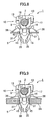
- FIG 8 shows a cable clamp 1 attached to a thin body panel 3. If the body panel 3 is thin, the shoulders 37 on the legs 15 of the fixed portion 5 interlock with edges of an attachment hole 42 at the ends. The elastic portions 38 on the flange 14 apply pressure to the body panel 3 without bending much.
- FIG 9 shows a cable clamp 1 attached to a thick body panel 3 A. If the body panel 3 is thick, the shoulders 37 on the legs 15 of the fixed portion 5 interlock with edges of an attachment hole 43 at the base. The elastic portions 38 on the flange 14 apply pressure to the body panel 3 while bent back. In this way, the cable clamp 1 is able to be securely attached to supports of varying thicknesses. Therefore, a single type of cable clamp can be used regardless of the thickness of the support.
Landscapes
- Engineering & Computer Science (AREA)
- General Engineering & Computer Science (AREA)
- Mechanical Engineering (AREA)
- Architecture (AREA)
- Civil Engineering (AREA)
- Structural Engineering (AREA)
- Clamps And Clips (AREA)
- Installation Of Indoor Wiring (AREA)
- Supports For Pipes And Cables (AREA)
Applications Claiming Priority (2)
| Application Number | Priority Date | Filing Date | Title |
|---|---|---|---|
| JP2003345747A JP2005113953A (ja) | 2003-10-03 | 2003-10-03 | ケーブルクランプ |
| JP2003345747 | 2003-10-03 |
Publications (1)
| Publication Number | Publication Date |
|---|---|
| EP1521024A1 true EP1521024A1 (de) | 2005-04-06 |
Family
ID=34309160
Family Applications (1)
| Application Number | Title | Priority Date | Filing Date |
|---|---|---|---|
| EP04023445A Withdrawn EP1521024A1 (de) | 2003-10-03 | 2004-10-01 | Klemmen für ein schlankes Objekt, zum Beispiel ein Kabel |
Country Status (4)
| Country | Link |
|---|---|
| US (1) | US20050079756A1 (de) |
| EP (1) | EP1521024A1 (de) |
| JP (1) | JP2005113953A (de) |
| CN (1) | CN1629529A (de) |
Cited By (6)
| Publication number | Priority date | Publication date | Assignee | Title |
|---|---|---|---|---|
| WO2007021437A3 (en) * | 2005-08-10 | 2007-05-18 | Illinois Tool Works | Dampening clip assembly |
| EP1653136A3 (de) * | 2004-10-26 | 2009-06-17 | Osram Sylvania Inc. | Schnapphalterung für Kabel |
| EP2365597A3 (de) * | 2010-03-10 | 2013-08-28 | Zumtobel Lighting GmbH | Drahthalter für eine Leuchte |
| EP2819252A1 (de) * | 2013-06-25 | 2014-12-31 | GE Lighting Solutions, LLC | Wirestrain-Entlastung zur Verwendung in einem Linearmodul einer lichtemittierenden Diode |
| EP3002495A1 (de) * | 2014-10-01 | 2016-04-06 | Newfrey LLC | Halter aus kunststoff zur schwingungsisolierenden befestigung eines länglichen gegenstands |
| WO2016058757A1 (de) * | 2014-10-17 | 2016-04-21 | Robert Bosch Gmbh | Befestigungsvorrichtung für eine leitung in einem fahrzeug |
Families Citing this family (21)
| Publication number | Priority date | Publication date | Assignee | Title |
|---|---|---|---|---|
| JP2004242478A (ja) * | 2003-02-10 | 2004-08-26 | Nippon Pop Rivets & Fasteners Ltd | ケーブルクランプ |
| JP2006353061A (ja) * | 2005-06-20 | 2006-12-28 | Daiwa Kasei Ind Co Ltd | ケーブル用クリップ |
| JP2009112092A (ja) * | 2007-10-29 | 2009-05-21 | Nippon Pop Rivets & Fasteners Ltd | 複数本のワイヤハーネスのクランプ |
| JP5066731B2 (ja) | 2008-03-18 | 2012-11-07 | ポップリベット・ファスナー株式会社 | 複数本のワイヤハーネスのクランプ |
| US7988173B2 (en) * | 2008-09-05 | 2011-08-02 | Sram, Llc | Bicycle suspension system |
| US20120112017A1 (en) * | 2009-07-07 | 2012-05-10 | Illinois Tool Works Inc. | Self-centering cable strap |
| DE102010043565A1 (de) * | 2010-11-08 | 2012-05-10 | Robert Bosch Gmbh | Befestigungsvorrichtung für eine Leitung und Verfahren zum Befestigen einer Leitung |
| US9550544B2 (en) | 2012-07-26 | 2017-01-24 | Shimano Inc. | Bicycle handlebar clamp assembly |
| US10483733B2 (en) * | 2012-10-09 | 2019-11-19 | Thomas & Betts International Llc | Joint strip |
| US9109617B2 (en) * | 2012-12-12 | 2015-08-18 | Newfrey Llc | Self-closing positive engagement clip |
| JP2017089841A (ja) * | 2015-11-16 | 2017-05-25 | 大和化成工業株式会社 | クリップ |
| WO2017143093A1 (en) | 2016-02-16 | 2017-08-24 | Golock Technology, Inc. | Portable lock with integrity sensors |
| DE102017115527B4 (de) | 2016-07-15 | 2024-12-05 | GM Global Technology Operations LLC | Clipanordnung zum halten einer Leitung |
| US10778285B2 (en) | 2017-01-04 | 2020-09-15 | Go Lock Technology, Inc. | Cable with integral sensing elements for fault detection |
| US10544605B2 (en) | 2017-05-19 | 2020-01-28 | Douglas A. Yates | Sliding lockable housing with supplemental openings |
| CN109322559B (zh) * | 2017-07-31 | 2020-08-04 | 英业达科技有限公司 | 锁固装置 |
| US10676151B2 (en) * | 2017-08-03 | 2020-06-09 | Shimano Inc. | Hydraulic operating device |
| JP6337298B2 (ja) * | 2017-09-12 | 2018-06-06 | 株式会社北電子 | 遊技機 |
| US10855024B2 (en) * | 2018-10-29 | 2020-12-01 | Te Connectivity Corporation | Electrical connector with latches and terminal position assurance projections provided on hinged cover |
| GB2583972B (en) * | 2019-05-17 | 2022-02-09 | Edwards Vacuum Llc | Latching device |
| CN222074189U (zh) * | 2023-12-12 | 2024-11-29 | 中山市凯恩德宠物用品有限公司 | 一种止食不倒翁玩具 |
Citations (3)
| Publication number | Priority date | Publication date | Assignee | Title |
|---|---|---|---|---|
| JPH10259884A (ja) | 1997-03-19 | 1998-09-29 | Piolax Inc | 配線、配管類の保持クリップ |
| DE19939081C1 (de) * | 1999-08-18 | 2000-10-26 | Raymond A & Cie | Rohrleitungshalter |
| WO2003001069A1 (en) | 2001-06-22 | 2003-01-03 | Newfrey Llc | Capped clip for pipe, electric cable or the like |
Family Cites Families (3)
| Publication number | Priority date | Publication date | Assignee | Title |
|---|---|---|---|---|
| JPH054297Y2 (de) * | 1985-02-07 | 1993-02-02 | ||
| US6809257B2 (en) * | 2001-06-22 | 2004-10-26 | Newfrey Llc | Capped clip for pipe, electric cable or the like |
| JP2004242478A (ja) * | 2003-02-10 | 2004-08-26 | Nippon Pop Rivets & Fasteners Ltd | ケーブルクランプ |
-
2003
- 2003-10-03 JP JP2003345747A patent/JP2005113953A/ja active Pending
-
2004
- 2004-09-29 US US10/951,722 patent/US20050079756A1/en not_active Abandoned
- 2004-10-01 EP EP04023445A patent/EP1521024A1/de not_active Withdrawn
- 2004-10-08 CN CN200410100528.2A patent/CN1629529A/zh active Pending
Patent Citations (3)
| Publication number | Priority date | Publication date | Assignee | Title |
|---|---|---|---|---|
| JPH10259884A (ja) | 1997-03-19 | 1998-09-29 | Piolax Inc | 配線、配管類の保持クリップ |
| DE19939081C1 (de) * | 1999-08-18 | 2000-10-26 | Raymond A & Cie | Rohrleitungshalter |
| WO2003001069A1 (en) | 2001-06-22 | 2003-01-03 | Newfrey Llc | Capped clip for pipe, electric cable or the like |
Cited By (9)
| Publication number | Priority date | Publication date | Assignee | Title |
|---|---|---|---|---|
| EP1653136A3 (de) * | 2004-10-26 | 2009-06-17 | Osram Sylvania Inc. | Schnapphalterung für Kabel |
| WO2007021437A3 (en) * | 2005-08-10 | 2007-05-18 | Illinois Tool Works | Dampening clip assembly |
| US7404548B2 (en) | 2005-08-10 | 2008-07-29 | Illinois Tool Works Inc. | Dampening clip assembly |
| EP2365597A3 (de) * | 2010-03-10 | 2013-08-28 | Zumtobel Lighting GmbH | Drahthalter für eine Leuchte |
| EP2819252A1 (de) * | 2013-06-25 | 2014-12-31 | GE Lighting Solutions, LLC | Wirestrain-Entlastung zur Verwendung in einem Linearmodul einer lichtemittierenden Diode |
| US9837759B2 (en) | 2013-06-25 | 2017-12-05 | GE Lighting Solutions, LLC | Wirestrain relief to use on a light emitting diode linear module |
| EP3002495A1 (de) * | 2014-10-01 | 2016-04-06 | Newfrey LLC | Halter aus kunststoff zur schwingungsisolierenden befestigung eines länglichen gegenstands |
| EP3263966A1 (de) * | 2014-10-01 | 2018-01-03 | Newfrey LLC | Haltevorrichtung aus kunststoff für vibrationsisolierende befestigung eines länglichen gegenstandes |
| WO2016058757A1 (de) * | 2014-10-17 | 2016-04-21 | Robert Bosch Gmbh | Befestigungsvorrichtung für eine leitung in einem fahrzeug |
Also Published As
| Publication number | Publication date |
|---|---|
| JP2005113953A (ja) | 2005-04-28 |
| US20050079756A1 (en) | 2005-04-14 |
| CN1629529A (zh) | 2005-06-22 |
Similar Documents
| Publication | Publication Date | Title |
|---|---|---|
| EP1521024A1 (de) | Klemmen für ein schlankes Objekt, zum Beispiel ein Kabel | |
| EP1832791B1 (de) | Befestigungsvorrichtung | |
| US7575269B2 (en) | Connector connecting construction, a clamping member and a method of mounting a connector connecting construction | |
| US7201352B2 (en) | Cable clamp | |
| JP4733294B2 (ja) | パイプや電線等の蓋付きクリップ | |
| EP1415863A1 (de) | Befestigungselement zum Befestigen eines Bodenteppichs und eines Kabelbaums an einer Schwellenabdeckung | |
| JP2011230593A (ja) | カーペットクランプ | |
| KR20070051373A (ko) | 커넥터 요소를 위한 고정 장치 및 상기 장치를 구비한커넥터 | |
| EP0863058A2 (de) | Verbindung zwischen Wischerblatt und Wischerarm für Scheibenwischer | |
| CN103502548B (zh) | 把手基座的安装构造 | |
| JP4222653B2 (ja) | 物品取付具 | |
| JP2006202619A (ja) | コネクタ用電線カバー | |
| JP3678546B2 (ja) | 蓄電池の把手接続構造 | |
| EP1901400B1 (de) | Drahtabdeckung und Verschlusskonstruktion dafür | |
| JP2005143234A (ja) | ワイヤハーネス等の長尺部材の留め具 | |
| JPH10246209A (ja) | クランプ | |
| JP3235959B2 (ja) | 自動車用モール | |
| KR101908551B1 (ko) | 와이퍼 블레이드와 와이퍼 암의 연결장치 | |
| JP3696760B2 (ja) | 線状体固定具 | |
| KR20080003675U (ko) | 커넥터하우징 | |
| JP4414019B2 (ja) | 配線ダクトカバーの外れ止め装置 | |
| JP3850051B2 (ja) | パイプ支持具 | |
| JP3116827U (ja) | 線材保持具 | |
| JPH0537623Y2 (de) | ||
| JP2003231448A (ja) | バンパ取付用クリップ |
Legal Events
| Date | Code | Title | Description |
|---|---|---|---|
| PUAI | Public reference made under article 153(3) epc to a published international application that has entered the european phase |
Free format text: ORIGINAL CODE: 0009012 |
|
| AK | Designated contracting states |
Kind code of ref document: A1 Designated state(s): AT BE BG CH CY CZ DE DK EE ES FI FR GB GR HU IE IT LI LU MC NL PL PT RO SE SI SK TR |
|
| AX | Request for extension of the european patent |
Extension state: AL HR LT LV MK |
|
| 17P | Request for examination filed |
Effective date: 20050923 |
|
| AKX | Designation fees paid |
Designated state(s): DE ES FR GB IT |
|
| GRAP | Despatch of communication of intention to grant a patent |
Free format text: ORIGINAL CODE: EPIDOSNIGR1 |
|
| STAA | Information on the status of an ep patent application or granted ep patent |
Free format text: STATUS: THE APPLICATION IS DEEMED TO BE WITHDRAWN |
|
| 18D | Application deemed to be withdrawn |
Effective date: 20061228 |