EP1520692A2 - Vorrichtung zur Vakuumlaminierung - Google Patents
Vorrichtung zur Vakuumlaminierung Download PDFInfo
- Publication number
- EP1520692A2 EP1520692A2 EP04022164A EP04022164A EP1520692A2 EP 1520692 A2 EP1520692 A2 EP 1520692A2 EP 04022164 A EP04022164 A EP 04022164A EP 04022164 A EP04022164 A EP 04022164A EP 1520692 A2 EP1520692 A2 EP 1520692A2
- Authority
- EP
- European Patent Office
- Prior art keywords
- evacuation
- base plate
- cover sheet
- guides
- structures
- Prior art date
- Legal status (The legal status is an assumption and is not a legal conclusion. Google has not performed a legal analysis and makes no representation as to the accuracy of the status listed.)
- Granted
Links
Images






Classifications
-
- B—PERFORMING OPERATIONS; TRANSPORTING
- B32—LAYERED PRODUCTS
- B32B—LAYERED PRODUCTS, i.e. PRODUCTS BUILT-UP OF STRATA OF FLAT OR NON-FLAT, e.g. CELLULAR OR HONEYCOMB, FORM
- B32B37/00—Methods or apparatus for laminating, e.g. by curing or by ultrasonic bonding
- B32B37/10—Methods or apparatus for laminating, e.g. by curing or by ultrasonic bonding characterised by the pressing technique, e.g. using action of vacuum or fluid pressure
- B32B37/1018—Methods or apparatus for laminating, e.g. by curing or by ultrasonic bonding characterised by the pressing technique, e.g. using action of vacuum or fluid pressure using only vacuum
Definitions
- the present invention generally relates to a vacuum lamination apparatus, in particular to a vacuum lamination apparatus for processing lamination materials such as components of a solar cell module by a vacuum lamination process.
- the energy source of solar cells is deemed promising since this energy is safe, easy to handle, and clean.
- solar cells There are several types of solar cells; important types are single crystal silicon solar cells, polycrystalline silicon solar cells, amorphous silicon solar cells, and compound semiconductor solar cells. Among these solar cells, amorphous silicon solar cells allow producing flexible solar cells with relatively low cost and large area solar cells, and have begun to be applied to new areas recently.
- Fig. 16 is a schematic drawing of a conventional vacuum lamination apparatus, in which (A) is a perspective view and (B) is a sectional view along line A-A in (A).
- the conventional vacuum lamination apparatus comprises a base plate 1001, a tube 1003 arranged in a ring shape on the base plate and provided with evacuation holes 1002 opened on the inside wall of the tube, and a vacuum pump 1008.
- the tube 1003 is fixed onto the base plate 1001 with fixing material 1004.
- a cover sheet 1005 covering the whole ring shaped tube 1003 forms a processing space 1006 for a lamination process.
- the vacuum lamination process first, sheets of components 1007 of a solar cell module for constructing a solar cell module are arranged and layered in the vacuum lamination apparatus. Then, a so-called degassing process is conducted, in which air between the materials is removed by evacuation using the vacuum pump 1008. Continuing the evacuation, the materials are heated up to a temperature at which sealant materials contained in the components of the solar cell module can be cross-linked or cured, and held at this temperature for a predetermined time until the sealant materials are fully cured. After that, the materials are cooled down and the vacuum pump is stopped returning to the atmospheric pressure.
- Fig. 17 is a schematic drawing of a solar cell module manufactured by using a vacuum lamination apparatus.
- a thermo-adhesive front surface sealant material 1011 and a top surface covering member (surface protection film) 1012 are sequentially formed.
- a thermo-adhesive rear surface sealant material 1013 and rear surface reinforcing member 1014 are sequentially formed.
- a technique has been disclosed (see, for example, JP-A-09-051111 (paragraph numbers [0025], [0026], and Fig. 5)), in which an acute angle structure of the cover sheet is mitigated by means of provision of a buffer member along the inner side of the tube.
- Fig. 18 is a schematic sectional view of a conventional vacuum lamination apparatus provided with a buffer member along inside of the tube.
- Components 1020 of a solar cell module are sandwiched by materials 1026 for preventing escape of filler material filling the space around the components, and placed on the base plate 1021 through a net 1022 for forming an air flow layer.
- a buffer member 1024 with a cross-section of the character L, for example, is provided along the inner side of the tube 1023 placed in a ring form as shown in Fig. 18.
- a cover sheet 1025 covers the whole tube 1023, and degassing by evacuation is conducted.
- rigidity of the apparatus as a whole must be enhanced by intensifying adhesion between the base plate and the tube. Even if the base plate and the tube are firmly integrated together by welding, for example, satisfactory rigidity of the apparatus as a whole can hardly be attained because a member with a tube form is generally poor in flexural rigidity.
- an evacuation space is formed with an evacuation port that is a gap formed in inner side of the evacuation structure that is fixed on either opposing side of the base plate, and hermetically sealed against the base plate and the end plates. Evacuation in a lamination process is conducted through these evacuation spaces.
- a processing space for vacuum lamination process is formed by the cover sheet, and air in the processing space is evacuated through the evacuation ports of the evacuation structures.
- the guides bend the two peripheral side regions of the cover sheet without the evacuation structure and enhance geometrical moment of inertia of the cover sheet.
- guides are arranged on the base plate at both sides of the lamination material and bridge opposing evacuation structures.
- the guides bend two peripheral side regions of the cover sheet in a vacuum lamination process and enhance geometrical moment of inertia of the cover sheet. As a result, adhesiveness of the cover sheet enhances and air leakage is suppressed allowing performing high quality vacuum lamination process.
- FIG. 1 is a perspective view of a vacuum lamination apparatus (VL apparatus) of a first embodiment of the invention.
- a vacuum lamination apparatus 10 comprises a base plate 11, evacuation structures 12, end plates 13, a cover sheet 14, spacers 15, exhaust port 16, and a valve 17.
- Base plate 11 is a base of the VL apparatus 10 and is a member for placing a laminate module to be lamination processed.
- the base plate needs heat resistance, rigidity, and light weight.
- Material for the base plate 11 is principally selected from metals and alloys including iron or aluminum, among which stainless steel is favorable from the view points of weldability and corrosion resistance. While small thickness is desired to reduce the heat capacity and weight, since excessively small thickness results in poor rigidity, the thickness is preferably in the range of about 1.0 to 2.0 mm.
- An evacuation structure 12 has a triangular cross-section with a plurality of faces.
- the evacuation structure 12 comprises principally a face perpendicular to the base plate 11 and a face inclined at a predetermined angle relative to the base plate 11.
- the evacuation structures 12 are arranged at two opposing sides of the base plate 11 with each of the inclined faces facing towards the center of the base plate.
- the evacuation structure 12 has a gap with a constant distance to the base plate 11.
- the evacuation structure 12 needs heat resistance, rigidity, and light weight. Stainless steel is principally used for the material of the evacuation structure.
- End plate 13 is fixed to the opposing ends of the evacuation structures 12 in a hermetic condition, and seal the ends of the evacuation structure 12.
- Each end plate 13 preferably connects two evacuation structures 12 to secure rigidity of the VL apparatus 10.
- Cover sheet 14 covers the base plate 11 and the evacuation structures 12, and forms a space for the lamination process (hereinafter called "processing space”).
- the cover sheet 14 needs elasticity, heat resistance, flexibility, light weight, and air tightness in evacuation process.
- the material used is generally a silicone resin, which is an elastic material.
- This embodiment uses a silicone rubber (thickness: 2 mm, hardness: 50 Hs JIS A (measured in accordance with Japanese Industrial Standard (JIS) 6301), general use type silicone resin, manufactured by Tigers Polymer Corporation).
- Exhaust port 16 is a conduit for exhausting air from the VL apparatus 10, and terminates at a valve 17.
- the VL apparatus 10 is connected to an external vacuum pump 110 via a vent of the valve 17.
- an evacuation space is formed with an evacuation port that is a gap formed on the inner side of the evacuation structure 12 that is fixed on either opposing side of the base plate 11, and hermetic against the base plate 11 and the end plates 13.
- the exhaust port 16 is inserted to this evacuation space through the end plate 13. In a lamination process, air is exhausted from the processing space through the gap to the evacuation space. From the evacuation space, air is exhausted out through the exhaust port 16.
- evacuation structures 12 are arranged at the opposing sides of the base plate 11 and have triangular cross-sections forming the evacuation spaces 12v in the evacuation structure, lamination process is conducted in a simple and rigid structure.
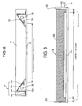
- Fig. 2 is a sectional view along line A1-A1 of Fig. 1.
- Fig. 3 is a sectional view along line A2-A2 of Fig. 1.
- Figs. 2 and 3 do not show spacers 15.
- the evacuation structure 12 consists of a first bent face 12a, a second bent face 12b, a third bent face 12c, and a fourth bent face 12d.
- the first bent face 12a and the second bent face 12b constitute an outer portion of the evacuation structure 12, while the third bent face 12c and the fourth bent face 12d constitute an inner portion of the evacuation structure 12.
- the third bent face 12c is bent with an elevation angle of 30 degrees with reference to the base plate 11 in this embodiment.
- the fourth bent face 12d is bent leaving a predetermined gap between the base plate 11 and the edge of the fold between the third bent face 12c and the fourth bent face 12d. This bending is conducted having the gap of about 2 mm in this embodiment.
- the fourth bent face 12d is bent from the third bent face 12c leaving a predetermined length of sealing ranges on both sides of the gap, the sealing range preventing air exhaust.
- the sealing range is 10 mm long in this embodiment.
- the evacuation structure 12 having the above described structure is fixed to the base plate 11 by butt resistance welding between the first bent face 12a and the outer periphery of the base plate 11. Spot welding is conducted at every 100 mm in this embodiment. By applying a spot welding method to fix the evacuation structure 12 to the base plate 11, time for welding is saved, and cost of manufacturing the VL apparatus 10 is lowered.
- An airtight structure is constructed by fixing the evacuation structures 12 to the base plate 11 and to the end plates 13, and by sealing with sealant the joints between the evacuation structures 12 and the base plate 11, between the evacuation structures 12 and the end plates 13, and between the base plate 11 and the end plates 13.
- the airtight structure forms an evacuation space 12v, as shown in Fig. 2, in each evacuation structure 12 fixed on the two opposing sides of the base plate 11.
- An evacuation port of the evacuation space is the gap between the base plate 11 and the folded edge of the third bent face 12c and the fourth bent face 12d.
- Shapes of solar cell modules are being elongate, particularly in the modules for roofing materials. Accordingly, the processing space is also elongate. Therefore, the evacuation structures in which the evacuation space 12v is formed are preferably arranged at the opposing longer sides of the base plate 11.
- Fig. 4 is a sectional view along line A1-A1 of Fig. 1 showing a lamination process
- Fig. 5 is a sectional view along line A2-A2 of Fig. 1 showing a lamination process.
- an air permeable sheet 21 is placed on the base plate 11, as shown in Fig. 4. Components of a laminate module that is a solar cell module in this embodiment are put thereon. Another air permeable sheet 21 is put thereon. Spacers 15 are laid in the gaps between the evacuation structures 12 and the base plate 11. The spacers 15 are plain weave wire net of stainless steel with a wire diameter of 0.9 mm and mesh number of 3 in this embodiment. A processing space is formed by covering the base plate 11 and the evacuation structure 12 with the cover sheet 14.
- the cover sheet 14 is arranged to overlap in an overlapping range D the sealing range on each end of the evacuation structures 12.
- the overlapping range D is at least 2 mm in this embodiment.
- components 20 of the solar cell module and the air permeable sheets 21 are omitted.
- Lamination process is performed in the VL apparatus 10 having the above described structure using the external vacuum pump 110.
- the cover sheet 14 pushes the components 20 of the solar cell module towards the base plate 11 and promotes degassing of the materials of the components 20 of the solar cell module.
- vacuum differential pressure generated by this degassing causes deflection of the third bent face 12c of the evacuation structure 12
- the spacer 15 prevents the deflected third bent face 12c and the base plate 11 from contacting each other and avoids blockage of air flow in the evacuation process.
- the air exhausted through the spacer 15 is vent outward from the evacuation space 12v through the exhaust port 16 that is inserted to the evacuation space 12v.
- Provision of the spacers 15 for maintaining the gap between the evacuation structures 12 and the base plate 11 secures air exhaust through the gaps in the evacuation process, and avoids degradation of evacuation performance.
- the laminate module is a solar cell module.
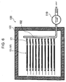
- Fig. 6 shows an example of a lamination module manufacturing system to which the VL apparatus is applied.
- Ten VL apparatuses 10 are horizontally arranged in a hot gas convection furnace 101 in the manufacturing system 100.
- the vent of the valve 17 of each VL apparatus 10 is connected to a manifold 102, which in turn connects to a vacuum pump 110, to evacuate all the VL apparatuses 10 together at one time.
- each VL apparatus 10 an air permeable sheet 21 is laid on the base plate 11, as in Fig. 4, then, components 20 of a solar cell module are placed thereon, and another air permeable sheet 21 is put thereon.
- a cover sheet 14 is placed to make an overlapping range D of the area covered by the cover sheet 14 and the sealing range of the evacuation structure 12 not smaller than 2 mm.
- a processing space is formed in each VL apparatus 10.
- each VL apparatus 10 After arranging each member, the vent of the valve 17 of each VL apparatus 10 is connected to the manifold 102. Then, the vacuum pump 110 starts to evacuate each processing space of the vacuum lamination devices 10 and degasses air between the components 20 of the solar cell module disposed in each VL apparatus 10.
- the apparatuses While degassing by the vacuum pump 110, the apparatuses are heated up to a temperature (about 150°C) at which filler material contained in the components 20 of the solar cell module starts to cure, and are held at this temperature for about 30 min until completion of curing.
- a temperature about 150°C
- the VL apparatuses 10 After closing the valve 17 of the VL apparatuses 10, the VL apparatuses 10 are taken out from the hot gas convection furnace 22 maintaining the vacuum, and cooled. After that, the valve 17 is opened and the processing space of each VL apparatus is returned to atmospheric pressure.
- the evacuation structure 12 has a triangular cross-section. However a nearly triangular shape may also be taken, that is a trapezoid in which the top edge is deformed to a flat plane.
- the second bent face 12b is bent perpendicular to the base plate 11 in the above description. However, the bent face can be bent inwardly slanted with respect to the base plate 11.
- the end plates 13 that hermetically fix both ends of the evacuation structures 12 are independent members in the above description.
- the end plates 13 can be formed by bending shorter edges of the base plate 11. Because the base plate 11 and the end plate 13 have a single integral structure in this case, the number of steps for manufacturing the VL apparatus 10 is reduced.
- the spacer 15 that secures the gap between an evacuation structure 12 and the base plate 11 is a wire net in the above description.
- the wire net can be replaced by another material as long as the material secures the gap and allows air flow.
- the manufacturing system 100 is used for manufacturing solar cell modules in the above description.
- the manufacturing system can also be used for manufacturing other types of laminate modules.
- the apparatus of the first embodiment involves a risk of air leakage as described below.
- the risk can be eliminated by the second embodiment according to the present invention.
- the risk of air leakage involved in the first embodiment will be described before description of the second embodiment.
- two peripheral side areas of the cover sheet 14 come into contact with the flat base plate 11 to hold the processing space in an airtight condition.
- the cover sheet 14 makes close contact with the base plate 11 only at the inner edge of the contact area with vacuum differential pressure, while outside of the inner edge it makes loose contact in the atmospheric pressure.
- the close contact edge works as a seal point.
- the region spanning between the seal points generated at the two peripheral sides of the cover sheet 14 develops vacuum differential pressure.
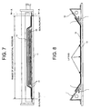
- the cover sheet 14 With heating the VL apparatus after start of evacuation, the cover sheet 14 expands by the heat. In the two peripheral sides of the cover sheet 14, as shown in Fig. 8, left and right ends of each peripheral side in the Fig. 8 are constrained by the ascending parts of the evacuation structures. As a result, some spots in the thermally expanded peripheral side region lift up from the base plate 11 and adhesiveness in the seal point deteriorates.
- Fig. 9 is a perspective view of an exemplary VL apparatus of the second embodiment according to the invention.
- Fig. 10 is a sectional view along line A-A of Fig. 9, and
- Fig. 11 is a sectional view along line B-B of Fig. 9.
- This example of the second embodiment of a VL apparatus 10' of the invention comprises the base plate 11 for placing a lamination material (which is components of a solar cell module in the following description), the cover sheet 14 that covers the lamination material and forms a processing space for vacuum lamination process, evacuation structures 12L arranged on the base plate 11 on both sides of the lamination material and having each an evacuation port 12h in the side of the evacuation structures facing each other for evacuating a processing space, slender slab-like members 12W arranged opposing each other on the base plate 11 on both sides of the lamination material and bridging the two evacuation structures 12L, and end the plates 13 sealing each end of the evacuation structures 12L.
- the VL apparatus 10' further comprises an exhaust port 16 that is a path connecting the evacuation structure 12L to a vacuum pump 110, and a valve 17.
- the base plate 11 is a member composing a base of the VL apparatus 10'.
- Protrusions and dents 11a are formed on a surface of the base plate 11 contacting the components of the solar cell module in this embodiment.
- the area of protrusions and dents 11a works as an air-flow bed or layer in a degassing process.
- the protrusions and dents 11a preferably have a pitch of 0.3 to 0.8 mm and a vertical difference or height of 0.2 to 0.6 mm.
- the air-flow layer of the protrusions and dents 11a formed on the base plate 11 preserves heat conduction to the components of the solar cell module and achieves enough air flow.
- the outer periphery of the area of protrusions and dents 11a preferably extends beyond the periphery of the components of a solar cell module to be placed thereon.
- the area of protrusions and dents 11a in this embodiment extends to the inner edge of the slab-like members 12W as shown in Fig. 11. This structure improves evacuation efficiency of the VL apparatus and contributes to suppress lifting of the cover sheet 14 by means of enhancement of flexural rigidity of the cover sheet 14, which is described later.
- Base plate 11 needs heat resistance, rigidity, and light weight in a VL apparatus of this embodiment used for manufacturing a solar cell module.
- the material for the base plate is principally selected from metals and alloys including iron or aluminum, among which stainless steel is favorable from the view points of ease of fabrication, weldability, and corrosion resistance. While small thickness is desired to reduce heat capacity and weight, since excessively small thickness results in poor rigidity, the thickness is preferably in a range of 0.8 to 2.0 mm.
- the evacuation structures 12L are arranged and fixed on the base plate 11 opposing each other on either side of the components of the solar cell module. Both ends of the evacuation structures are sealed by end plates 13.
- the evacuation structures 12L like the base plate 11, need heat resistance, rigidity, and light weight.
- the material used for the evacuation structures can be again stainless steel.
- the second bent face 12Lb is bent at about a right angle from the first bent face 12La.
- the third bent face 12Lc is bent at a narrow angle of about 30° with respect to the base plate 11.
- the fourth bent face 12Ld is bent such that a bent edge of the third bent face 12Lc and the fourth bent face 12Ld has a gap with a predetermined distance from the base plate 11.
- the gap is 2 mm high in this embodiment.
- the cover sheet 14 gently slopes along the third bent face 12Lc, avoiding an abrupt bend that stresses the cover sheet 14 and might cause cracks in the cover sheet.
- productivity of a VL apparatus is improved.
- the cross-section of the evacuation structure 12L can have a nearly triangular shape that is a trapezoid in which the top edge is modified to a flat surface.
- the fourth bent face 12Ld is bent from the third bent face 12c leaving a predetermined length of sealing ranges on both sides of the gap, the sealing ranges prohibiting air exhaustion.
- the sealing range is 10 mm long, for example.
- the gap produced by such a bend functions as an evacuation port 12h.
- the fifth bent face 12Le is bent from the third bent face 12Lc.
- the fifth bent face 12Le is bent with right angle with respect to the base plate 11. Since the gap is 2 mm in this embodiment, the fifth bent face is also 2 mm high from the base plate.
- An evacuation space 12v is formed by the evacuation structure 12L and the base plate 11.
- the evacuation space 12v evacuates air in the processing space through the evacuation port 12h.
- An exhaust port 16 is inserted into the evacuation space 12v through the end plate 13 for connection to a vacuum pump 110.
- the air in the processing space sealed by the cover sheet 14 is evacuated through the evacuation port 12h to the evacuation space 12v, from which the air is further evacuated through the exhaust port 16.
- the slab-like member 12W works in the vacuum lamination process as a guide to form a bend in the cover sheet 14 at the two peripheral side regions where no evacuation structure 12L is provided.
- the slab-like member is made of, for example, stainless steel as is the evacuation structure 12L.
- the slab-like member consists of a first bent face 12Wc and a second bent face 12We, as shown in Fig. 11.
- the first bent face 12Wc is bent ascending at a predetermined angle towards the periphery of the base plate 11.
- the second bent face 12We is bent standing at a right angle from the base plate 11. If the predetermined angle mentioned above is steep or nearly flat with respect to the base plate 11, three dimensional distortions would develop in the cover sheet 14 at a butted corner position formed by the tip of the slab-like member 12W and the evacuation structure 12L. Slack would be generated in the cover sheet 14 around this position causing air leakage. Accordingly, the predetermined angle is favorably determined so that the first bent face 12Wc is appropriately gently sloping with respect to the base plate 11. This predetermined angle is about 30° in this embodiment.
- the height of the second bent face 12We is preferably in the range of 2 to 3 mm for avoiding the three dimensional distortion of the cover sheet 14. In this embodiment, this height is 2 mm that allows joining with the fifth bent face 12Le of the evacuation structure 12L.
- the slab-like member 12W is butted to the base plate 11 so that the second bent face 12We is perpendicular to the base plate 11.
- Each end of the slab-like member 12W is butted to the evacuation structure 12L such that the first bent face 12Wc and the second bent face 12We of the slab-like member meet the third bent face 12Lc and the fifth bent face 12Le of the evacuation structure, respectively.
- the first bent face 12La of the evacuation structure 12L is butted with the outer periphery of the base plate 11 and spot-welded at every 100 mm by means of electric resistance welding, for example. Joining by the spot welding prevents welding distortion and makes the welding time short, thus reducing manufacturing cost of the VL apparatus.
- sealant for avoiding leakage in the evacuation process. Sealing is made with the silicone sealant "KE45" in this embodiment (the same as in the first embodiment). Sealant adhesion portions are preferably degreased before the adhesion process.
- the airtight structure using sealant material allows avoiding difficult hermetic welding, and thus, reduces manufacturing cost while ensuring reliability of the VL apparatus.
- the end plates 13 seal off both ends of the evacuation structures 12L.
- the end plates 13 in this embodiment are spot-welded by TIG welding, and sealed at the joint parts with sealant material.
- the end plates 13 preferably extend integrally connecting the opposing evacuation structures 12L to ensure rigidity of the VL apparatus 10'.
- end portions of the base plate 11 can be bent and used for the end plates. This structure reduces manufacturing steps of the VL apparatus.
- the cover sheet 14 is used for covering the components of a solar cell module and generating a processing space, pushing the components towards the base plate 11 while evacuating through the evacuation space 12v, and promoting degassing from the components of the solar cell module.
- the cover sheet 14 needs elasticity, heat resistance, flexibility, light weight, and air tightness on evacuation.
- Elastic material used is principally a silicone resin, for example, a silicone rubber (thickness: 2 mm, hardness: 50 Hs JIS A, general use silicone resin manufactured by Tigers Polymer Corporation). Although fluororubber can be used, silicone resin is superior in flexibility and cost.
- the shape of the processing space is oblong.
- the opposing evacuation structures 12L for forming evacuation spaces 12v are preferably located on the longer sides of the base plate.
- W is the distance between the opposing evacuation ports 12h (see Fig. 10) and L is the length of the evacuation port (see Fig. 11), the relation L ⁇ W is preferably satisfied. Since the evacuation spaces 12v are formed on the longer sides of the base plate 11 under this condition, sufficient evacuation is carried out for a vacuum lamination process even though the evacuation spaces 12v are formed only on the opposing two sides. By this means, a vacuum lamination process can be performed on a solar cell module with a long size and a large area (for example, a size of 500 mm x 2,000 mm).
- Fig. 12 shows a schematic construction of components of a solar cell module to be processed by vacuum lamination using a VL apparatus according to the invention.
- the components 18 of a solar cell module to be laminated comprise, from the top to the bottom in the figure, a rear surface reinforcing member 18a, a thermo-adhesive sealant 18b, a photovoltaic element 18c, a thermo-adhesive sealant 18d, and a front surface covering member 18e.
- a vacuum lamination process in this embodiment is conducted with the light receiving face of the photovoltaic element arranged facing the base plate 11 ("face down" arrangement).
- the front surface covering member 18e has an outer dimension larger than those of the other components of the solar cell module to prevent the thermo-adhesive sealant 18b and 18d flowing out of the components from adhering to the base plate 11 in the vacuum lamination process.
- Light from the outside of the thus formed solar cell module enters through the front surface covering member 18e that is a transparent resin film on the outermost surface, and reaches the photovoltaic element 18c. Generated electromotive force is drawn out from output terminals not shown in the figure.
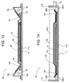
- Fig. 13 is a sectional view showing a vacuum lamination process
- Fig. 14 is another sectional view showing the vacuum lamination process.
- Fig. 13 corresponds to Fig. 10, which shows an A-A cross-section of the VL apparatus 10'
- Fig. 14 corresponds to Fig. 11, which shows a B-B cross-section of the apparatus.
- components 18 of a solar cell module are placed on an area of protrusions and dents 11a of the base plate 11.
- a releasing sheet 21 is placed on the components for preventing the thermo-adhesive sealant 18b and 18d flowing out of the components from adhering to the cover sheet 14.
- the cover sheet 14 is put on the materials.
- the releasing sheet 21 contacts over the whole surface of the rear surface reinforcing member 18a of the components 18 of the solar cell module. Since the rear surface reinforcing member 18a is made of a material without air permeability such as steel plate, the releasing sheet 21 is not necessarily a material exhibiting air permeability.
- the vacuum pump 110 starts to evacuate the processing space 19 formed by the cover sheet 14.
- the cover sheet 14 pushes the components 18 of the solar cell module towards the base plate 11 and promotes degassing air between materials of the components 18.
- the protrusions and dents 11a formed on the base plate 11 form an air-flow layer and further promote degassing.
- the components 18 of the solar cell module are heated up to a temperature at which the thermo-adhesive sealant 18b and 18d cures (for example 150°C) and are held at that temperature until completion of the curing (for example, 30 min).
- the valve 17 is closed and the VL apparatus 10' is cooled while maintaining the vacuum inside the apparatus.
- the valve 17 is opened to return the processing space to the atmospheric pressure.
- both peripheral side regions of the cover sheet 14 at which no evacuation structure is arranged form bends 14a and 14b by means of the slab-like members 12W as shown in Fig. 14.
- Fig. 15 shows a bend formed at a peripheral side region of the cover sheet.
- Fig. 15 is an enlarged drawing of the bend 14a in Fig.14.
- the protrusions and dents 11a formed on the base plate 11 reach the innermost part of the slab-like member 12W in this embodiment, and so, the processing space 19 is evacuated reaching the innermost part of the slab-like member 12W.
- the cover sheet 14 closely contacts with the slab-like member 12W at the corner (that is the connecting point between the first bent face 12Wc and the second bent face 12We). The close contact point works as a sealing point.
- the cover sheet 14 is bent at the sealing point formed at the corner of the slab-like member 12W and then ascends along the first bent face 12Wc of the slab-like member 12W.
- a bend 14a is formed in the cover sheet 14 and the geometrical moment of inertia of the cover sheet 14 increases.
- a schematic construction of a solar cell module manufacturing system that employs a VL apparatus of the second embodiment of the invention is the same as the schematic construction of the manufacturing system employing a VL apparatus of the first embodiment, and shown in Fig. 6.
- the VL apparatus 10' arranged in the solar cell module manufacturing system 100 as shown in Fig. 6 shows a sectional view with solar cell module disposed in a processing space and corresponds to the arrangement in Fig. 13.
- the solar cell module manufacturing system 100 comprises a hot gas convection furnace 101, for example, in which a VL apparatus 10 of this embodiment of the invention as described so far is installed.
- the solar cell module manufacturing system 100 as shown in Fig. 6 allows manufacturing ten sheets of solar cell modules at one time.
- Each VL apparatus 10 connects to an exhaust manifold 102 in the furnace 101 through the valve 17 fitted to the exhaust port 16.
- the vacuum pump 110 starts and the power source of the furnace 101 is switched on to heat the VL apparatus while evacuating a processing space of the apparatus.
- the both peripheral side regions of the cover sheet 14 are bent by the slab-like member 12W and the geometrical moment of inertia of the cover sheet 14 is enhanced.
- lifting of the cover sheet 14 along the seal point is sufficiently suppressed. Therefore, adhesiveness along the seal point of the cover sheet 14 is enhanced and leakage to the processing space 19 is satisfactorily suppressed to accomplish high quality vacuum lamination.
- the suppression of leakage to the processing space 19 in the VL apparatus 10' of this embodiment allows the degree of vacuum in the processing space 19 to be maintained at 133 Pa (1 Torr), for example.
- the protrusions and dents 11a extend to the innermost part of the slab-like member 12W in the structure described above.
- the cover sheet 14 closely contacts with the base plate in the interval creating a seal point. Even in such a case, the slab-like member 12W generates a bend in the peripheral side region of the cover sheet. Accordingly, the geometrical moment of inertia of the cover sheet increases and the adhesiveness of the cover sheet along the seal point is improved to suppress leakage.
- the slab-like member 12W is used in the above embodiment as a guide to form a bend in the peripheral side region of the cover sheet 14.
- other types of slab-like member can also be used that have a bend in the cross-section of the member.
- An end portion of the base plate 11 can be formed to produce such a bent shape as a guide without using any independent member as described above.
- a guide for bending the peripheral side region of the cover sheet 14 can be a columnar member having a cross-section protruding from the base plate 11 or a part having a like cross-section formed on the base plate 11.
- Use of such a type of columnar member heaves the cover sheet 14 from the base plate 11 and generates a bend in the lamination process and increases the geometrical moment of inertia of the cover sheet 14.
- Examples of such members include a member with a trapezoidal cross-section having a plane ascending towards a periphery of the base plate, and a bar with a round cross-section.
- the diameter of such a bar with a round cross-section is preferably in the range of 2 to 3 mm for avoiding three dimensional distortion in the cover sheet 14 around a corner at which the end of the bar and the evacuation structure are butted.
- the bar with a round cross-section leads to lower working cost.
- the above description has been made on vacuum lamination process that is conducted in a face-down arrangement of the components 18 of a solar cell module.
- a face-up arrangement can also be taken in the vacuum lamination process.
- the releasing sheet 21 is favorably an air permeating material.
Landscapes
- Physics & Mathematics (AREA)
- Fluid Mechanics (AREA)
- Photovoltaic Devices (AREA)
- Casting Or Compression Moulding Of Plastics Or The Like (AREA)
- Laminated Bodies (AREA)
Applications Claiming Priority (4)
| Application Number | Priority Date | Filing Date | Title |
|---|---|---|---|
| JP2003340345A JP4314955B2 (ja) | 2003-09-30 | 2003-09-30 | 真空ラミネート装置及び真空ラミネート方法 |
| JP2003340345 | 2003-09-30 | ||
| JP2004001671 | 2004-01-07 | ||
| JP2004001671A JP4254542B2 (ja) | 2004-01-07 | 2004-01-07 | 真空ラミネート装置 |
Publications (3)
| Publication Number | Publication Date |
|---|---|
| EP1520692A2 true EP1520692A2 (de) | 2005-04-06 |
| EP1520692A3 EP1520692A3 (de) | 2006-05-03 |
| EP1520692B1 EP1520692B1 (de) | 2009-03-25 |
Family
ID=34315719
Family Applications (1)
| Application Number | Title | Priority Date | Filing Date |
|---|---|---|---|
| EP04022164A Expired - Lifetime EP1520692B1 (de) | 2003-09-30 | 2004-09-17 | Vorrichtung zur Vakuumlaminierung |
Country Status (5)
| Country | Link |
|---|---|
| US (1) | US7452439B2 (de) |
| EP (1) | EP1520692B1 (de) |
| CN (1) | CN100484758C (de) |
| DE (1) | DE602004020164D1 (de) |
| ES (1) | ES2322353T3 (de) |
Cited By (3)
| Publication number | Priority date | Publication date | Assignee | Title |
|---|---|---|---|---|
| DE102008044862A1 (de) * | 2008-08-28 | 2010-03-04 | Robert Bürkle GmbH | Verfahren und Laminierpresse zum Laminieren von Werkstücken |
| WO2011089473A3 (en) * | 2010-01-19 | 2011-10-06 | 3S Swiss Solar Systems Ag | System and method for laminating modules |
| CN102529276A (zh) * | 2010-12-28 | 2012-07-04 | 中电电气(上海)太阳能科技有限公司 | 一种太阳能层压机硅胶板防护装置 |
Families Citing this family (7)
| Publication number | Priority date | Publication date | Assignee | Title |
|---|---|---|---|---|
| TWI276535B (en) * | 2005-12-07 | 2007-03-21 | Nano Prec Corp | Film attaching method and screen of rear projection television |
| CN101821073A (zh) * | 2007-05-18 | 2010-09-01 | R·W.·吕丁 | 用于树脂传递和其它工艺的具有一体式流体传递导管和密封的真空袋 |
| US20080302031A1 (en) * | 2007-06-05 | 2008-12-11 | Solar Roofing Systems, Inc., | Integrated solar roofing tile connection system |
| US9656450B2 (en) | 2008-01-02 | 2017-05-23 | Tpk Touch Solutions, Inc. | Apparatus for laminating substrates |
| CN102259459B (zh) * | 2010-12-21 | 2014-09-10 | 吴江市博众精工科技有限公司 | 一种贴膜定位装置 |
| CN109904100B (zh) * | 2019-03-20 | 2021-10-01 | 英利能源(中国)有限公司 | 光伏组件层压室、层压设备及层压方法 |
| DE102021122287B4 (de) * | 2021-08-27 | 2024-01-18 | Premium Aerotec Gmbh | Verfahren und System zum Beschichten einer Oberfläche eines metallischen Trägerprofils mit einer Schicht aus einem korrosionsresistenten Material |
Family Cites Families (17)
| Publication number | Priority date | Publication date | Assignee | Title |
|---|---|---|---|---|
| US3666600A (en) * | 1969-03-10 | 1972-05-30 | North American Rockwell | Apparatus for forming layup laminate |
| JPS60194093A (ja) | 1984-03-14 | 1985-10-02 | Mitsui Eng & Shipbuild Co Ltd | 電着被膜形成方法 |
| GB9006253D0 (en) | 1990-03-20 | 1990-05-16 | Short Brothers Plc | An evacuation chamber |
| JPH04281982A (ja) | 1991-03-07 | 1992-10-07 | H F G Kikaku Kk | 横型ウインドウシャッター |
| JPH076489A (ja) | 1993-03-11 | 1995-01-10 | Victor Co Of Japan Ltd | ディスクプレーヤ |
| JP2948506B2 (ja) | 1995-08-10 | 1999-09-13 | キヤノン株式会社 | 真空ラミネート装置及び太陽電池の製造法 |
| JP2948507B2 (ja) | 1995-08-10 | 1999-09-13 | キヤノン株式会社 | 真空ラミネート装置及び太陽電池の製造法 |
| JP3176264B2 (ja) | 1995-08-10 | 2001-06-11 | キヤノン株式会社 | 真空ラミネート装置 |
| US6007650A (en) * | 1995-08-10 | 1999-12-28 | Canon Kabushiki Kaisha | Vacuum laminating apparatus and method |
| JP2948508B2 (ja) | 1995-08-10 | 1999-09-13 | キヤノン株式会社 | 真空ラミネート装置および真空ラミネート方法並びに太陽電池の製造法 |
| US5993582A (en) * | 1996-08-13 | 1999-11-30 | Canon Kabushiki Kaisha | Continuous vacuum lamination treatment system and vacuum lamination apparatus |
| JP3689498B2 (ja) | 1996-08-13 | 2005-08-31 | キヤノン株式会社 | 真空ラミネーション装置及びその製造方法 |
| JP2991682B2 (ja) | 1997-08-11 | 1999-12-20 | スワン商事株式会社 | 横引シャッター雨戸 |
| JPH1187743A (ja) | 1997-09-11 | 1999-03-30 | Canon Inc | モジュールの真空ラミネート方法 |
| FR2814109B1 (fr) | 2000-09-19 | 2003-09-26 | Aerovac Systeme France Sarl | Dispositif d'aspiration participant d'un dispositif de drainage des gaz par depression pour le moulage de produits sous vide tels que par exemple des produits stratifies |
| JP2002364266A (ja) | 2001-06-05 | 2002-12-18 | Eidai Co Ltd | 雨 戸 |
| JP2004306420A (ja) | 2003-04-07 | 2004-11-04 | Fuji Electric Holdings Co Ltd | 真空ラミネート装置および真空ラミネート方法 |
-
2004
- 2004-08-24 US US10/923,897 patent/US7452439B2/en not_active Expired - Fee Related
- 2004-09-17 ES ES04022164T patent/ES2322353T3/es not_active Expired - Lifetime
- 2004-09-17 DE DE602004020164T patent/DE602004020164D1/de not_active Expired - Lifetime
- 2004-09-17 EP EP04022164A patent/EP1520692B1/de not_active Expired - Lifetime
- 2004-09-30 CN CNB200410081033XA patent/CN100484758C/zh not_active Expired - Fee Related
Cited By (4)
| Publication number | Priority date | Publication date | Assignee | Title |
|---|---|---|---|---|
| DE102008044862A1 (de) * | 2008-08-28 | 2010-03-04 | Robert Bürkle GmbH | Verfahren und Laminierpresse zum Laminieren von Werkstücken |
| WO2011089473A3 (en) * | 2010-01-19 | 2011-10-06 | 3S Swiss Solar Systems Ag | System and method for laminating modules |
| CN102958696A (zh) * | 2010-01-19 | 2013-03-06 | 3S瑞士太阳能系统股份公司 | 用于层压组件的设备和方法 |
| CN102529276A (zh) * | 2010-12-28 | 2012-07-04 | 中电电气(上海)太阳能科技有限公司 | 一种太阳能层压机硅胶板防护装置 |
Also Published As
| Publication number | Publication date |
|---|---|
| ES2322353T3 (es) | 2009-06-19 |
| EP1520692B1 (de) | 2009-03-25 |
| US20050077006A1 (en) | 2005-04-14 |
| US7452439B2 (en) | 2008-11-18 |
| CN1624937A (zh) | 2005-06-08 |
| DE602004020164D1 (de) | 2009-05-07 |
| EP1520692A3 (de) | 2006-05-03 |
| CN100484758C (zh) | 2009-05-06 |
Similar Documents
| Publication | Publication Date | Title |
|---|---|---|
| US8408263B2 (en) | Vacuum lamination device | |
| EP1520692B1 (de) | Vorrichtung zur Vakuumlaminierung | |
| JP4687130B2 (ja) | 真空ラミネート装置、および真空ラミネート方法 | |
| US6241839B1 (en) | Continuous vacuum lamination treatment system and vacuum lamination apparatus | |
| JP4829172B2 (ja) | 真空断熱パネル | |
| JP4254542B2 (ja) | 真空ラミネート装置 | |
| CN111033842B (zh) | 电池单元 | |
| JP2002151711A (ja) | 薄膜太陽電池の裏面封止方法 | |
| JP2004306420A (ja) | 真空ラミネート装置および真空ラミネート方法 | |
| KR100242854B1 (ko) | 진공 적층 장치 및 방법 | |
| JP2004311571A (ja) | 太陽電池モジュールの製造方法 | |
| US9651278B2 (en) | Method for manufacturing a vacuum solar thermal panel and related vacuum solar thermal panel | |
| CN107107557A (zh) | 具有改进的密封接头的真空绝热板 | |
| JP5128687B2 (ja) | 太陽電池モジュールの製造方法、および該製造方法によって製造した太陽電池モジュール | |
| JPH10275626A (ja) | 積層燃料電池 | |
| JP4314955B2 (ja) | 真空ラミネート装置及び真空ラミネート方法 | |
| JP3746419B2 (ja) | 真空保持容器 | |
| JP4946420B2 (ja) | 真空ラミネート装置および真空ラミネート方法 | |
| JP3689498B2 (ja) | 真空ラミネーション装置及びその製造方法 | |
| JPH0951113A (ja) | 真空ラミネート装置 | |
| JPH0951111A (ja) | 真空ラミネート装置 | |
| KR102646167B1 (ko) | 기밀형 하우징 프레임 및 그에 결합되는 기밀형 덮개 | |
| CN223513991U (zh) | 用于膜电极的封装装置及封装系统 | |
| JP5884140B2 (ja) | 太陽電池モジュール、及び太陽電池モジュールの製造方法 | |
| JP2008153578A (ja) | 真空ラミネート装置および真空ラミネート方法 |
Legal Events
| Date | Code | Title | Description |
|---|---|---|---|
| PUAI | Public reference made under article 153(3) epc to a published international application that has entered the european phase |
Free format text: ORIGINAL CODE: 0009012 |
|
| AK | Designated contracting states |
Kind code of ref document: A2 Designated state(s): AT BE BG CH CY CZ DE DK EE ES FI FR GB GR HU IE IT LI LU MC NL PL PT RO SE SI SK TR |
|
| AX | Request for extension of the european patent |
Extension state: AL HR LT LV MK |
|
| RIC1 | Information provided on ipc code assigned before grant |
Ipc: 7B 32B 31/20 A Ipc: 7B 30B 5/02 B |
|
| PUAL | Search report despatched |
Free format text: ORIGINAL CODE: 0009013 |
|
| AK | Designated contracting states |
Kind code of ref document: A3 Designated state(s): AT BE BG CH CY CZ DE DK EE ES FI FR GB GR HU IE IT LI LU MC NL PL PT RO SE SI SK TR |
|
| AX | Request for extension of the european patent |
Extension state: AL HR LT LV MK |
|
| 17P | Request for examination filed |
Effective date: 20060707 |
|
| AKX | Designation fees paid |
Designated state(s): DE ES FR |
|
| 17Q | First examination report despatched |
Effective date: 20070816 |
|
| GRAP | Despatch of communication of intention to grant a patent |
Free format text: ORIGINAL CODE: EPIDOSNIGR1 |
|
| RIC1 | Information provided on ipc code assigned before grant |
Ipc: B32B 5/02 20060101ALI20080930BHEP Ipc: B32B 37/10 20060101AFI20080930BHEP |
|
| GRAS | Grant fee paid |
Free format text: ORIGINAL CODE: EPIDOSNIGR3 |
|
| GRAA | (expected) grant |
Free format text: ORIGINAL CODE: 0009210 |
|
| AK | Designated contracting states |
Kind code of ref document: B1 Designated state(s): DE ES FR |
|
| REF | Corresponds to: |
Ref document number: 602004020164 Country of ref document: DE Date of ref document: 20090507 Kind code of ref document: P |
|
| REG | Reference to a national code |
Ref country code: ES Ref legal event code: FG2A Ref document number: 2322353 Country of ref document: ES Kind code of ref document: T3 |
|
| PLBE | No opposition filed within time limit |
Free format text: ORIGINAL CODE: 0009261 |
|
| STAA | Information on the status of an ep patent application or granted ep patent |
Free format text: STATUS: NO OPPOSITION FILED WITHIN TIME LIMIT |
|
| 26N | No opposition filed |
Effective date: 20091229 |
|
| REG | Reference to a national code |
Ref country code: DE Ref legal event code: R081 Ref document number: 602004020164 Country of ref document: DE Owner name: FUJI ELECTRIC CO., LTD., KAWASAKI-SHI, JP Free format text: FORMER OWNER: FUJI ELECTRIC SYSTEMS CO., LTD., TOKYO/TOKIO, JP Effective date: 20110826 Ref country code: DE Ref legal event code: R082 Ref document number: 602004020164 Country of ref document: DE Representative=s name: HOFFMANN, ECKART, DIPL.-ING., DE Effective date: 20110826 |
|
| REG | Reference to a national code |
Ref country code: FR Ref legal event code: TP Owner name: FUJI ELECTRIC CO., LTD., JP Effective date: 20111021 |
|
| REG | Reference to a national code |
Ref country code: ES Ref legal event code: PC2A Owner name: FUJI ELECTRIC CO., LTD Effective date: 20111227 |
|
| PGFP | Annual fee paid to national office [announced via postgrant information from national office to epo] |
Ref country code: DE Payment date: 20140911 Year of fee payment: 11 |
|
| PGFP | Annual fee paid to national office [announced via postgrant information from national office to epo] |
Ref country code: ES Payment date: 20140812 Year of fee payment: 11 |
|
| PGFP | Annual fee paid to national office [announced via postgrant information from national office to epo] |
Ref country code: FR Payment date: 20140906 Year of fee payment: 11 |
|
| REG | Reference to a national code |
Ref country code: DE Ref legal event code: R119 Ref document number: 602004020164 Country of ref document: DE |
|
| REG | Reference to a national code |
Ref country code: FR Ref legal event code: ST Effective date: 20160531 |
|
| PG25 | Lapsed in a contracting state [announced via postgrant information from national office to epo] |
Ref country code: DE Free format text: LAPSE BECAUSE OF NON-PAYMENT OF DUE FEES Effective date: 20160401 |
|
| PG25 | Lapsed in a contracting state [announced via postgrant information from national office to epo] |
Ref country code: FR Free format text: LAPSE BECAUSE OF NON-PAYMENT OF DUE FEES Effective date: 20150930 |
|
| REG | Reference to a national code |
Ref country code: ES Ref legal event code: FD2A Effective date: 20161028 |
|
| PG25 | Lapsed in a contracting state [announced via postgrant information from national office to epo] |
Ref country code: ES Free format text: LAPSE BECAUSE OF NON-PAYMENT OF DUE FEES Effective date: 20150918 |