EP1519672B1 - Bodenbearbeitungssystem - Google Patents
Bodenbearbeitungssystem Download PDFInfo
- Publication number
- EP1519672B1 EP1519672B1 EP03735619A EP03735619A EP1519672B1 EP 1519672 B1 EP1519672 B1 EP 1519672B1 EP 03735619 A EP03735619 A EP 03735619A EP 03735619 A EP03735619 A EP 03735619A EP 1519672 B1 EP1519672 B1 EP 1519672B1
- Authority
- EP
- European Patent Office
- Prior art keywords
- floor treatment
- treatment system
- charging station
- connecting elements
- unit
- Prior art date
- Legal status (The legal status is an assumption and is not a legal conclusion. Google has not performed a legal analysis and makes no representation as to the accuracy of the status listed.)
- Expired - Lifetime
Links
- 230000008878 coupling Effects 0.000 claims abstract description 10
- 238000010168 coupling process Methods 0.000 claims abstract description 10
- 238000005859 coupling reaction Methods 0.000 claims abstract description 10
- 238000001514 detection method Methods 0.000 claims description 21
- 238000000605 extraction Methods 0.000 claims 2
- 239000002689 soil Substances 0.000 description 34
- 238000003971 tillage Methods 0.000 description 11
- 238000012545 processing Methods 0.000 description 7
- 238000003032 molecular docking Methods 0.000 description 6
- 238000004140 cleaning Methods 0.000 description 5
- 230000005540 biological transmission Effects 0.000 description 3
- 238000000034 method Methods 0.000 description 3
- 238000010408 sweeping Methods 0.000 description 3
- 230000002349 favourable effect Effects 0.000 description 2
- 230000005855 radiation Effects 0.000 description 2
- 238000012546 transfer Methods 0.000 description 2
- 238000013459 approach Methods 0.000 description 1
- 238000004891 communication Methods 0.000 description 1
- 239000012530 fluid Substances 0.000 description 1
- 238000004519 manufacturing process Methods 0.000 description 1
- 230000001681 protective effect Effects 0.000 description 1
- 238000012549 training Methods 0.000 description 1
Images


Classifications
-
- A—HUMAN NECESSITIES
- A47—FURNITURE; DOMESTIC ARTICLES OR APPLIANCES; COFFEE MILLS; SPICE MILLS; SUCTION CLEANERS IN GENERAL
- A47L—DOMESTIC WASHING OR CLEANING; SUCTION CLEANERS IN GENERAL
- A47L9/00—Details or accessories of suction cleaners, e.g. mechanical means for controlling the suction or for effecting pulsating action; Storing devices specially adapted to suction cleaners or parts thereof; Carrying-vehicles specially adapted for suction cleaners
- A47L9/10—Filters; Dust separators; Dust removal; Automatic exchange of filters
- A47L9/106—Dust removal
-
- A—HUMAN NECESSITIES
- A47—FURNITURE; DOMESTIC ARTICLES OR APPLIANCES; COFFEE MILLS; SPICE MILLS; SUCTION CLEANERS IN GENERAL
- A47L—DOMESTIC WASHING OR CLEANING; SUCTION CLEANERS IN GENERAL
- A47L9/00—Details or accessories of suction cleaners, e.g. mechanical means for controlling the suction or for effecting pulsating action; Storing devices specially adapted to suction cleaners or parts thereof; Carrying-vehicles specially adapted for suction cleaners
- A47L9/009—Carrying-vehicles; Arrangements of trollies or wheels; Means for avoiding mechanical obstacles
-
- A—HUMAN NECESSITIES
- A47—FURNITURE; DOMESTIC ARTICLES OR APPLIANCES; COFFEE MILLS; SPICE MILLS; SUCTION CLEANERS IN GENERAL
- A47L—DOMESTIC WASHING OR CLEANING; SUCTION CLEANERS IN GENERAL
- A47L9/00—Details or accessories of suction cleaners, e.g. mechanical means for controlling the suction or for effecting pulsating action; Storing devices specially adapted to suction cleaners or parts thereof; Carrying-vehicles specially adapted for suction cleaners
- A47L9/28—Installation of the electric equipment, e.g. adaptation or attachment to the suction cleaner; Controlling suction cleaners by electric means
- A47L9/2805—Parameters or conditions being sensed
-
- A—HUMAN NECESSITIES
- A47—FURNITURE; DOMESTIC ARTICLES OR APPLIANCES; COFFEE MILLS; SPICE MILLS; SUCTION CLEANERS IN GENERAL
- A47L—DOMESTIC WASHING OR CLEANING; SUCTION CLEANERS IN GENERAL
- A47L9/00—Details or accessories of suction cleaners, e.g. mechanical means for controlling the suction or for effecting pulsating action; Storing devices specially adapted to suction cleaners or parts thereof; Carrying-vehicles specially adapted for suction cleaners
- A47L9/28—Installation of the electric equipment, e.g. adaptation or attachment to the suction cleaner; Controlling suction cleaners by electric means
- A47L9/2836—Installation of the electric equipment, e.g. adaptation or attachment to the suction cleaner; Controlling suction cleaners by electric means characterised by the parts which are controlled
- A47L9/2842—Suction motors or blowers
-
- A—HUMAN NECESSITIES
- A47—FURNITURE; DOMESTIC ARTICLES OR APPLIANCES; COFFEE MILLS; SPICE MILLS; SUCTION CLEANERS IN GENERAL
- A47L—DOMESTIC WASHING OR CLEANING; SUCTION CLEANERS IN GENERAL
- A47L9/00—Details or accessories of suction cleaners, e.g. mechanical means for controlling the suction or for effecting pulsating action; Storing devices specially adapted to suction cleaners or parts thereof; Carrying-vehicles specially adapted for suction cleaners
- A47L9/28—Installation of the electric equipment, e.g. adaptation or attachment to the suction cleaner; Controlling suction cleaners by electric means
- A47L9/2836—Installation of the electric equipment, e.g. adaptation or attachment to the suction cleaner; Controlling suction cleaners by electric means characterised by the parts which are controlled
- A47L9/2852—Elements for displacement of the vacuum cleaner or the accessories therefor, e.g. wheels, casters or nozzles
-
- A—HUMAN NECESSITIES
- A47—FURNITURE; DOMESTIC ARTICLES OR APPLIANCES; COFFEE MILLS; SPICE MILLS; SUCTION CLEANERS IN GENERAL
- A47L—DOMESTIC WASHING OR CLEANING; SUCTION CLEANERS IN GENERAL
- A47L9/00—Details or accessories of suction cleaners, e.g. mechanical means for controlling the suction or for effecting pulsating action; Storing devices specially adapted to suction cleaners or parts thereof; Carrying-vehicles specially adapted for suction cleaners
- A47L9/28—Installation of the electric equipment, e.g. adaptation or attachment to the suction cleaner; Controlling suction cleaners by electric means
- A47L9/2857—User input or output elements for control, e.g. buttons, switches or displays
-
- A—HUMAN NECESSITIES
- A47—FURNITURE; DOMESTIC ARTICLES OR APPLIANCES; COFFEE MILLS; SPICE MILLS; SUCTION CLEANERS IN GENERAL
- A47L—DOMESTIC WASHING OR CLEANING; SUCTION CLEANERS IN GENERAL
- A47L9/00—Details or accessories of suction cleaners, e.g. mechanical means for controlling the suction or for effecting pulsating action; Storing devices specially adapted to suction cleaners or parts thereof; Carrying-vehicles specially adapted for suction cleaners
- A47L9/28—Installation of the electric equipment, e.g. adaptation or attachment to the suction cleaner; Controlling suction cleaners by electric means
- A47L9/2868—Arrangements for power supply of vacuum cleaners or the accessories thereof
- A47L9/2873—Docking units or charging stations
-
- A—HUMAN NECESSITIES
- A47—FURNITURE; DOMESTIC ARTICLES OR APPLIANCES; COFFEE MILLS; SPICE MILLS; SUCTION CLEANERS IN GENERAL
- A47L—DOMESTIC WASHING OR CLEANING; SUCTION CLEANERS IN GENERAL
- A47L9/00—Details or accessories of suction cleaners, e.g. mechanical means for controlling the suction or for effecting pulsating action; Storing devices specially adapted to suction cleaners or parts thereof; Carrying-vehicles specially adapted for suction cleaners
- A47L9/28—Installation of the electric equipment, e.g. adaptation or attachment to the suction cleaner; Controlling suction cleaners by electric means
- A47L9/2868—Arrangements for power supply of vacuum cleaners or the accessories thereof
- A47L9/2884—Details of arrangements of batteries or their installation
-
- H—ELECTRICITY
- H01—ELECTRIC ELEMENTS
- H01R—ELECTRICALLY-CONDUCTIVE CONNECTIONS; STRUCTURAL ASSOCIATIONS OF A PLURALITY OF MUTUALLY-INSULATED ELECTRICAL CONNECTING ELEMENTS; COUPLING DEVICES; CURRENT COLLECTORS
- H01R13/00—Details of coupling devices of the kinds covered by groups H01R12/70 or H01R24/00 - H01R33/00
- H01R13/02—Contact members
- H01R13/22—Contacts for co-operating by abutting
- H01R13/24—Contacts for co-operating by abutting resilient; resiliently-mounted
-
- A—HUMAN NECESSITIES
- A47—FURNITURE; DOMESTIC ARTICLES OR APPLIANCES; COFFEE MILLS; SPICE MILLS; SUCTION CLEANERS IN GENERAL
- A47L—DOMESTIC WASHING OR CLEANING; SUCTION CLEANERS IN GENERAL
- A47L2201/00—Robotic cleaning machines, i.e. with automatic control of the travelling movement or the cleaning operation
- A47L2201/02—Docking stations; Docking operations
- A47L2201/022—Recharging of batteries
-
- A—HUMAN NECESSITIES
- A47—FURNITURE; DOMESTIC ARTICLES OR APPLIANCES; COFFEE MILLS; SPICE MILLS; SUCTION CLEANERS IN GENERAL
- A47L—DOMESTIC WASHING OR CLEANING; SUCTION CLEANERS IN GENERAL
- A47L2201/00—Robotic cleaning machines, i.e. with automatic control of the travelling movement or the cleaning operation
- A47L2201/02—Docking stations; Docking operations
- A47L2201/024—Emptying dust or waste liquid containers
Definitions
- the invention relates to a soil cultivation system having the features of the preamble of claim 1.
- a floor surface can be edited, in particular cleaned, without the tillage unit must be performed by an operator on the floor surface along. Rather, the soil tillage unit is designed such that it automatically moves along the ground surface and processes it. If it encounters an obstacle, this is detected by the soil treatment unit, which then changes its direction of travel to avoid the obstacle.
- the state of charge of the energy supply unit is monitored by an electrical control of the soil cultivation unit. If the state of charge falls below a predetermined limit value, then the soil cultivation unit automatically controls the central charging station, at which the energy supply unit can be recharged.
- mutually associated electrical connecting elements are arranged on the soil treatment unit and the charging station, can be transmitted via the electrical energy.
- Such tillage systems are for example off WO99 / 28800 A . DE 298 24 552 U and from US 6 076 226 A known.
- Object of the present invention is to develop a soil cultivation system of the type mentioned in such a way that it allows for improved electrical coupling of the associated connecting elements.
- the electrical coupling of the connecting elements can be improved when docking the tillage unit to the associated charging station.
- a resilient support is particularly avoided that in comparison to the charging station relatively easy soil treatment unit is repelled when hitting the charging station of the charging station, so that the associated connecting elements then have such a large distance from each other that an effective energy transfer is no longer possible is.
- the ground-working unit according to the invention has a collision detection sensor, which is associated with a resiliently held feeler element whose movement relative to a chassis of the soil working unit for providing a collision detection signal is detectable.
- a collision detection sensor which is associated with a resiliently held feeler element whose movement relative to a chassis of the soil working unit for providing a collision detection signal is detectable.
- a bumper surrounding the tilling unit in the circumferential direction may be used, which is resiliently mounted relative to a chassis of the tillage unit so that the bumper performs a relative movement to the landing gear when the tiller unit encounters an obstacle. This relative movement is detected by the collision detection sensor of the soil treatment unit, which then changes its direction of travel.
- collision detection sensors are for example from EP 0 274 310 B1 known.
- the ground handling unit encounters the charging station with such a collision detection sensor, there is a risk that the impact will trigger a collision detection signal and the ground processing unit will subsequently reverse its direction of travel so that an electrical coupling of the associated connecting elements is not possible. If, however, at least one of the connecting elements is resiliently held, the groundworking unit can temporarily retain its original direction of movement due to the spring travel permitted by the connecting element without the collision detection sensor already becoming active and triggering a reversal of the direction of travel, while the mutually associated connecting elements are already in electrical contact with one another and thus a charging current can flow from the charging station to the power unit of the tilling unit.
- the charging current can be detected by the controller of the soil processing unit, so that a subsequent collision detection signal of the collision detection sensor can be suppressed. This ensures that the soil tillage unit does not recognize the loading station as an obstacle when docking, which is to be avoided. Rather, the soil treatment unit for recharging the power supply unit takes a desired position to the charging station, so that the mutually associated connection elements can electrically connect with each other.
- the spring constant of the resiliently held electrical connection element is less than the spring constant of the collision detection sensor.
- a charging current can flow before the collision detection sensor detects a collision with the resiliently held feeler element, for example a protective strip surrounding the floor treatment unit in the circumferential direction, and triggers a reversal of the direction of travel.
- the resiliently held feeler element for example a protective strip surrounding the floor treatment unit in the circumferential direction
- the use of a lower spring strength for the resiliently held connecting element than for the resiliently held feeler element of the collision detection sensor makes it possible, in particular, for the docking of the soil treatment unit to the central charging station to be able to suppress a collision detection signal until the charging process has ended. After recharging the charging state exceeds a predetermined limit, so that subsequently the collision detection signal is releasable and the tillage unit thus performs a reversal direction and continues the processing of the bottom surface.
- the electrical coupling of the associated connecting elements can be done without contact by electrical energy is inductively or capacitively transferable.
- the mutually associated connection elements form electrical contact elements for ohmic coupling of the soil treatment unit with the charging station.
- This allows a structurally particularly simple embodiment of the associated connecting elements, wherein it is necessary for the transmission of electrical energy that the electrical contact elements designed as connecting elements touch each other, so that a charging current can flow.
- the tillage system has at least two first connecting elements, each of which is assigned at least one second connecting element.
- a faulty orientation of the soil treatment unit in the vertical direction can be compensated by the fact that the first connecting elements are arranged at a vertical distance from each other.
- At least one first connecting element a plurality of spaced apart second connecting elements are assigned. It is particularly advantageous if, depending on the orientation of the soil treatment unit relative to the charging station, one or more of the second connecting elements are electrically connectable to a first connecting element. In an optimal alignment of the soil treatment unit relative to the charging station, for example, two second connecting elements may be electrically connected to a common first connecting element, while in a misalignment of the soil working unit only a second connecting element with the associated first connecting element is connectable.
- the second connecting elements are arranged in a preferably horizontally oriented plane.
- a plurality of second connecting elements can be arranged in the horizontal direction next to one another at the loading station or at the ground processing unit.
- a particularly reliable coupling of the mutually associated connection elements can be achieved in that at least one of the mutually associated connection elements is designed flat. Due to the planar configuration, an extended contact area is provided, which simplifies the transmission of electrical energy.
- the planar connection element may be formed, for example, strip-shaped.
- the flat connecting element is resiliently held.
- the flat configured connecting element forms a leaf spring. This allows a cost-effective production and assembly of the resiliently held connection element.
- the area configured connecting element is arranged at the charging station.
- a plurality of contact elements are assigned to the areally configured connecting element. This gives the possibility that when docking the soil treatment unit to the charging station at least one of the contact elements impinges on the associated surface configured connecting element, so that a charging current can flow.
- two horizontally oriented, leaf-spring-like connecting elements are arranged one above the other at the charging station, each of which at least two contact elements held on the soil cultivation unit are assigned.
- the two leaf spring-like connecting elements can be acted upon by a power source of the charging station with voltage of different polarity.
- the tillage system enables, among other things, the cleaning of a floor surface.
- the soil cultivation unit can form a mobile suction device with a suction turbine and a dirt collecting container having a suction inlet. Starting from the suction inlet, a suction flow can be caused by the suction turbine be so that dirt can be picked up from the bottom surface and transferred to the dirt collector.
- a brush roller with the suction inlet sweeping sweeping brushes is rotatably driven drivable. This makes it possible not only to suck the floor surface but also to brush.
- the charging station comprises a suction unit and a dirt receptacle, wherein during recharging of the power supply unit at the same time the dirt collecting container via the suction inlet of the suction unit is sucked.
- the dirt collector of the suction device can be emptied.
- an inventive soil cultivation system in the form of a total occupied by the reference numeral 10 floor cleaning system is shown, which includes a central charging station 12 and a self-propelled and self-controlling soil treatment unit in the form of a mobile suction device 14.
- the suction device 14 is designed as a mobile cleaning robot and has a housing 16 with a top wall 18 and a bottom wall 20, which define a suction channel 22 between them.
- the housing 16 In its rear region, the housing 16 carries a suction turbine 26, which is driven in rotation by an electric drive motor 24 and which is in fluid communication with the suction channel 22 via an intake connection 28.
- the bottom wall 20 has in its front, the suction turbine 26 facing away from a suction inlet 30 which is penetrated by sweeping brushes 32 of a rotationally drivable brush roller 34.
- a dirt filter 36 is disposed, and the area between the brush roller 34 and the dirt filter 36 forms a dirt collecting 38.
- a suction flow is generated, with their help dirt from the bottom surface through the suction inlet 30th can be transferred through the dirt collecting 38.
- the dirt receptacle from the bottom surface is supported by the brush roller 34 here.
- the housing 16 forms a chassis of the mobile suction device 14, in which two drive wheels 40 are rotatably mounted in a known per se and therefore not shown in the drawing, each of which is assigned a known drive motor (not shown).
- the housing 16 is circumferentially surrounded by a resiliently mounted on the housing 16 Tastring 42, on which a cover 44 is placed.
- a cover 44 is placed on the housing 16 Tastring 42, on which a cover 44 is placed.
- the touch ring 42 and the cover 44 are in FIG. 2 not shown.
- the ceiling wall 18 carries a rechargeable power supply unit in the form of a rechargeable battery 46 and additionally receives an electrical control 48 and each in the area above a drive wheel 40, two infrared photosensitive sensors 50 and a Hall sensor 52.
- a relative movement of the on the touch ring 42nd seated cover 44 relative to the housing 16 are detected. If such a relative movement occurs, a collision detection signal is transmitted to the controller 48 by the Hall sensor 52.
- Such relative movement occurs upon impact of the suction device 14 on an obstacle. Due to the collision detection signal, the direction of travel of the suction device 14 can then be changed, in particular, a reversal of direction can take place.
- the suction device 14 can automatically start the charging station 12 to recharge the battery 46th
- the charging station has a housing 54 which surrounds a suction unit 56 and a dirt receptacle 58, which can be acted upon by the suction unit 56 with negative pressure.
- a boom 60 is held, which carries four infrared light-emitting diodes 62, 63, 64, 65 at its free end.
- a ramp 66 is formed on the housing 54 of the charging station 12, which has a suction opening 68.
- a suction channel 70 connects, which forms a flow connection between the suction opening 68 and the dirt receptacle 58th
- the boom 60 has on its ramp 66 facing bottom a stepped support plate 72 with a housing 54 facing rear support plate portion 74 and a housing 54 facing away from the front support plate portion 76, which are integrally connected via a step 78 together.
- another infrared light emitting diode 80 is disposed.
- an infrared target radiation is emitted, which is detected by the infrared photosensitive sensors 50 of the suction device 14 depending on the direction and with the help of the suction device 14 can automatically control the charging station 12.
- the suction device 14 moves when docking to the charging station 12 on the ramp 66, so that the suction inlet 30 is aligned with the suction 68.
- Dirt flow symbolized by the arrows 82 can then be used to transfer dirt from the dirt collecting container 38 of the mobile suction device 14 via the suction inlet 30 into the dirt receptacle 58 of the charging station 12.
- the battery 46 of the suction device 14 is recharged.
- two electrical connection elements in the form of two leaf springs 86, 88 are held on a supporting wall 84 connecting the rear support plate portion 74 of the boom 60 with the ramp 66, the springs being clamped between two support elements 90, 92 fixed to the support wall 84.
- the two prestressed and convexly curved leaf springs 86 and 88 are connected via connecting lines, not shown in the drawing with a positive pole or the negative terminal of a known per se and therefore not shown in the drawing electrical voltage source of the charging station 12.
- the Voltage source can be connected by means of a per se known power cord to the mains voltage.
- the two leaf springs 86 and 88 are each associated with two rigidly held on the cover 44 of the suction device 14 electrical contact pins.
- a first contact pin 94 and a second contact pin 96 cooperate with the leaf spring 86, and a third contact pin 98 positioned below the first contact pin 94 and a fourth contact pin (not shown in the drawing) disposed below the second contact pin 96 act on the leaf spring 88 together.
- Hit the contact pins on the two leaf springs 86 and 88, as shown in the FIGS. 6 and 7 is shown, so can be transferred from the charging station 12, electrical energy to the suction device 14 by a charge current flows to the battery 46 via the leaf springs 86, 88 and the contact pins.
- a further approximation of the suction device 14 to the charging station 12 causes the two leaf springs 86 and 88 due to their elasticity an evasive movement along a in FIG. 9 Run shown spring travel 102.
- the spring constant of the two leaf springs 86 and 88 is in this case selected to be smaller than the spring constant of the resilient support of the touch ring 42. This ensures that the leaf springs 86 and 88 can initially perform a resilient deflection movement and a charging current can flow before the Hall sensor 52, a collision detection signal is provided relative to the housing 16 due to a relative movement of the cover 44 and the sensing ring 42.
- the controller 48 first detects the flow of a charging current to the battery 46, so that a subsequent one adjusting collision detection signal can be suppressed until the charging process is completed. Subsequently, the collision detection signal is released, so that the suction device 14 performs a reversal of direction and now moves in the charging station 12 facing away from the direction. Thus, the recharging of the battery 46 and the simultaneous suction of the dirt collecting container 38 is completed and the suction device 14 can resume its normal operation for cleaning the bottom surface.
Landscapes
- Engineering & Computer Science (AREA)
- Mechanical Engineering (AREA)
- Robotics (AREA)
- Control Of Position, Course, Altitude, Or Attitude Of Moving Bodies (AREA)
- Charge And Discharge Circuits For Batteries Or The Like (AREA)
- Electric Vacuum Cleaner (AREA)
- Agricultural Machines (AREA)
- Platform Screen Doors And Railroad Systems (AREA)
- Vehicle Body Suspensions (AREA)
- Soil Working Implements (AREA)
Description
- Die Erfindung betrifft ein Bodenbearbeitungssystem mit den Merkmalen des Oberbegriffes von Patentanspruch 1.
- Mit Hilfe selbstfahrender und selbststeuemder Bodenbearbeitungseinheiten kann eine Bodenfläche bearbeitet, insbesondere gereinigt werden, ohne daß die Bodenbearbeitungseinheit von einer Bedienungsperson an der Bodenfläche entlang geführt werden muß. Die Bodenbearbeitungseinheit ist vielmehr derart ausgestaltet, daß sie selbsttätig an der Bodenfläche entlangfährt und diese bearbeitet. Trifft sie auf ein Hindernis, so wird dies von der Bodenbearbeitungseinheit erkannt, die daraufhin ihre Fahrtrichtung ändert, um dem Hindernis auszuweichen.
- Die Bearbeitung der Bodenfläche erfolgt mittels eines Bodenbearbeitungsaggregates, das von der Bodenbearbeitungseinheit mitgeführt wird und das von einer Energieversorgungseinheit mit elektrischer Energie versorgt wird. Der Ladezustand der Energieversorgungseinheit wird von einer elektrischer Steuerung der Bodenbearbeitungseinheit überwacht. Unterschreitet der Ladezustand einen vorgegebenen Grenzwert, so steuert die Bodenbearbeitungseinheit selbsttätig die zentrale Ladestation an, an der die Energieversorgungseinheit wieder aufgeladen werden kann. Zu diesem Zweck sind an der Bodenbearbeitungseinheit und an der Ladestation einander zugeordnete elektrische Verbindungselemente angeordnet, über die elektrische Energie übertragen werden kann. Derartige Bodenbearbeitungssysteme sind beispielsweise aus
WO99/28800 A DE 298 24 552 U und ausUS 6 076 226 A bekannt. - Zur möglichst verlustarmen Übertragung von elektrischer Energie von der Ladestation zur Bodenbearbeitungseinheit ist es erforderlich, daß die einander zugeordneten elektrischen Verbindungselemente elektrisch miteinander gekoppelt werden können. Es hat sich gezeigt, daß bei bekannten Bodenbearbeitungssystemen eine derartige elektrische Kopplung nicht in allen Fällen zuverlässig erzielbar ist.
- Aufgabe der vorliegenden Erfindung ist es, ein Bodenbearbeitungssystem der eingangs genannten Art derart weiterzubilden, daß es eine verbesserte elektrische Kopplung der einander zugeordneten Verbindungselemente ermöglicht.
- Diese Aufgabe wird durch ein Bodenbearbeitungssystem mit den Merkmalen von Patentanspruch 1 gelöst.
- Durch eine federnde Halterung von zumindest einem der einander zugeordneten Verbindungselemente kann die elektrische Kopplung der Verbindungselemente beim Andocken der Bodenbearbeitungseinheit an die zugeordnete Ladestation verbessert werden. Durch eine derartige federnde Halterung wird insbesondere vermieden, daß die im Vergleich zur Ladestation relativ leichte Bodenbearbeitungseinheit beim Auftreffen auf die Ladestation von der Ladestation zurückgestoßen wird, so daß die einander zugeordneten Verbindungselemente anschließend einen derart großen Abstand zueinander aufweisen, daß eine wirkungsvolle Energieübertragung nicht mehr möglich ist.
- Der Einsatz von zumindest einem federnd gehaltenen elektrischen Verbindungselement ist vor allem deshalb von Vorteil, da die Bodenbearbeitungseinheit erfindungsgemäß über einen Kollisionserkennungssensor verfügt, dem ein federnd gehaltenes Tastelement zugeordnet ist, dessen Bewegung relativ zu einem Fahrwerk der Bodenbearbeitungseinheit zur Bereitstellung eines Kollisionserkennungssignals erfaßbar ist. So kann beispielsweise eine die Bodenbearbeitungseinheit in Umfangsrichtung umgebende Stoßleiste zum Einsatz kommen, die relativ zu einem Fahrwerk der Bodenbearbeitungseinheit federnd gelagert ist, so daß die Stoßleiste eine Relativbewegung zum Fahrwerk ausführt, wenn die Bodenbearbeitungseinheit auf ein Hindernis trifft. Diese Relativbewegung wird vom Kollisionserkennungssensor der Bodenbearbeitungseinheit erkannt, die daraufhin ihre Fahrtrichtung ändert. Derartige Kollisionserkennungssensoren sind beispielsweise aus der
EP 0 274 310 B1 bekannt. Trifft die Bodenbearbeitungseinheit mit einem derartigen Kollisionserkennungssensor auf die Ladestation, so besteht die Gefahr, daß das Auftreffen ein Kollisionserkennungssignal auslöst und die Bodenbearbeitungseinheit anschließend ihre Fahrtrichtung umkehrt, so daß eine elektrische Kopplung der einander zugeordneten Verbindungselemente nicht möglich ist. Ist jedoch zumindest eines der Verbindungselemente federnd gehalten, so kann die Bodenbearbeitungseinheit aufgrund des dem Verbindungselement ermöglichten Federweges kurzzeitig noch ihre ursprüngliche Bewegungsrichtung beibehalten, ohne daß der Kollisionserkennungssensor bereits aktiv wird und eine Fahrtrichtungsumkehr auslöst, während jedoch die einander zugeordneten Verbindungselemente bereits elektrisch miteinander in Kontakt treten und folglich ein Ladestrom von der Ladestation zur Energieversorgungseinheit der Bodenbearbeitungseinheit fließen kann. Der Ladestrom kann von der Steuerung der Bodenbearbeitungseinheit erkannt werden, so daß ein anschließendes Kollisionserkennungssignal des Kollisionserkennungssensors unterdrückt werden kann. Dadurch ist sichergestellt, daß die Bodenbearbeitungseinheit beim Andocken die Ladestation nicht als Hindernis erkennt, dem auszuweichen ist. Vielmehr nimmt die Bodenbearbeitungseinheit zum Wiederaufladen der Energieversorgungseinheit eine gewünschte Position zur Ladestation ein, so daß die einander zugeordneten Verbindungselemente elektrisch miteinander in Verbindung treten können. Gemäß der vorliegenden Erfindung ist die Federkonstante des federnd gehaltenen elektrischen Verbindungselementes geringer als die Federkonstante des Kollisionserkennungssensors. Dadurch läßt sich auf konstruktiv einfache Weise sicherstellen, daß ein Ladestrom fließen kann, bevor der Kollisionserkennungssensor mit dem federnd gehaltenen Tastelement, beispielsweise einer die Bodenbearbeitungseinheit in Umfangsrichtung umgebenden Stoßleiste, eine Kollision erkennt und eine Fahrtrichtungsumkehr auslöst. Der Einsatz einer geringeren Federstärke für das federnd gehaltene Verbindungselement als für das federnd gehaltene Tastelement des Kollisionserkennungssensors ermöglicht es insbesondere, daß beim Andocken der Bodenbearbeitungseinheit an die zentrale Ladestation ein Kollisionserkennungssignal so lange unterdrückt werden kann, bis der Ladevorgang beendet ist. Nach erfolgtem Wiederaufladen überschreitet der Ladezustand einen vorgebbaren Grenzwert, so daß anschließend das Kollisionserkennungssignal freigebbar ist und die Bodenbearbeitungseinheit folglich eine Fahrtrichtungsumkehr ausführt und die Bearbeitung der Bodenfläche fortsetzt. - Die elektrische Kopplung der einander zugeordneten Verbindungselemente kann berührungslos erfolgen, indem elektrische Energie induktiv oder kapazitiv übertragbar ist.
- Bei einer bevorzugten Ausführungsform ist vorgesehen, daß die einander zugeordneten Verbindungselemente elektrische Kontaktelemente ausbilden zur ohmschen Kopplung der Bodenbearbeitungseinheit mit der Ladestation. Dies ermöglicht eine konstruktiv besonders einfache Ausgestaltung der zugeordneten Verbindungselemente, wobei es zur Übertragung elektrischer Energie erforderlich ist, daß die als elektrische Kontaktelemente ausgestalteten Verbindungselemente einander berühren, so daß ein Ladestrom fließen kann.
- Als günstig hat es sich erwiesen, wenn das Bodenbearbeitungssystem zumindest zwei erste Verbindungselemente aufweist, denen jeweils mindestens ein zweites Verbindungselement zugeordnet ist. Der Einsatz mehrerer erster und zweiter Verbindungselemente, die an der Bodenbearbeitungseinheit bzw. an der Ladestation angeordnet sind, stellt sicher, daß auch bei einer unpräzisen Ausrichtung der Bodenbearbeitungseinheit relativ zur Ladestation eine mechanische Kopplung zumindest eines ersten Verbindungselements mit einem zweiten Verbindungselement erzielbar ist.
- So kann beispielsweise eine fehlerhafte Orientierung der Bodenbearbeitungseinheit in vertikaler Richtung dadurch ausgeglichen werden, daß die ersten Verbindungselemente in vertikalem Abstand zueinander angeordnet sind.
- Bei einer bevorzugten Ausführungsform ist vorgesehen, daß mindestens einem ersten Verbindungselement mehrere im Abstand zueinander angeordnete zweite Verbindungselemente zugeordnet sind. Hierbei ist es besonders vorteilhaft, wenn in Abhängigkeit von der Ausrichtung der Bodenbearbeitungseinheit relativ zur Ladestation eines oder mehrere der zweiten Verbindungselemente mit einem ersten Verbindungselement elektrisch verbindbar sind. Bei einer optimalen Ausrichtung der Bodenbearbeitungseinheit relativ zur Ladestation können beispielsweise zwei zweite Verbindungselemente mit einem gemeinsamen ersten Verbindungselement elektrisch verbunden sein, während bei einer Fehlorientierung der Bodenbearbeitungseinheit lediglich ein zweites Verbindungselement mit dem zugeordneten ersten Verbindungselement verbindbar ist.
- Als günstig hat es sich erwiesen, wenn die zweiten Verbindungselemente in einer vorzugsweise horizontal ausgerichteten Ebene angeordnet sind. So können beispielsweise mehrere zweite Verbindungselemente in horizontaler Richtung nebeneinander an der Ladestation oder an der Bodenbearbeitungseinheit angeordnet sein.
- Eine besonders zuverlässige Kopplung der einander zugeordneten Verbindungselemente kann dadurch erzielt werden, daß mindestens eines der einander zugeordneten Verbindungselemente flächig ausgestaltet ist. Aufgrund der flächigen Ausgestaltung wird eine ausgedehnte Kontaktfläche bereitgestellt, die die Übertragung elektrischer Energie vereinfacht.
- Das flächige Verbindungselement kann beispielsweise streifenförmig ausgebildet sein.
- Vorzugsweise ist das flächige Verbindungselement federnd gehalten.
- So kann beispielsweise vorgesehen sein, daß das flächig ausgestaltete Verbindungselement eine Blattfeder ausbildet. Dies ermöglicht eine kostengünstige Herstellung und Montage des federnd gehaltenen Verbindungselementes.
- Von Vorteil ist es, wenn das flächig ausgestaltete Verbindungselement an der Ladestation angeordnet ist.
- Bei einer bevorzugten Ausführungsform sind dem flächig ausgestalteten Verbindungselement mehrere Kontaktelemente zugeordnet. Dies gibt die Möglichkeit, daß beim Andocken der Bodenbearbeitungseinheit an die Ladestation zumindest eines der Kontaktelemente auf das zugeordnete flächig ausgestaltete Verbindungselement auftrifft, so daß ein Ladestrom fließen kann.
- Bei einer besonders bevorzugten Ausführungsform des erfindungsgemäßen Bodenbearbeitungssystems ist vorgesehen, daß an der Ladestation zwei horizontal ausgerichtete, blattfederartige Verbindungselemente übereinander angeordnet sind, denen jeweils mindestens zwei an der Bodenbearbeitungseinheit gehaltene Kontaktelemente zugeordnet sind. Die beiden blattfederartigen Verbindungselemente können hierbei von einer Energiequelle der Ladestation mit Spannung unterschiedlicher Polarität beaufschlagt werden.
- Wie eingangs erwähnt, ermöglicht das erfindungsgemäße Bodenbearbeitungssystem unter anderem die Reinigung einer Bodenfläche. Hierzu kann die Bodenbearbeitungseinheit ein mobiles Sauggerät ausbilden mit einer Saugturbine und einem einen Saugeinlaß aufweisenden Schmutzsammelbehälter. Ausgehend vom Saugeinlaß kann von der Saugturbine eine Saugströmung hervorgerufen werden, so daß Schmutz von der Bodenfläche aufgenommen und in den Schmutzsammelbehälter überführt werden kann.
- Von Vorteil ist es hierbei, wenn am Saugeinlaß eine Bürstenwalze mit den Saugeinlaß durchgreifenden Kehrbürsten drehend antreibbar gelagert ist. Dies ermöglicht es, die Bodenfläche nicht nur abzusaugen sondern auch zu bürsten.
- Günstig ist es, wenn die Ladestation ein Absaugaggregat umfaßt sowie einen Schmutzaufnahmebehälter, wobei beim Wiederaufladen der Energieversorgungseinheit gleichzeitig der Schmutzsammelbehälter über den Saugeinlaß vom Absaugaggregat absaugbar ist. Beim Andocken der Bodenbearbeitungseinheit an der Ladestation kann folglich nicht nur Energie übertragen werden zum Wiederaufladen der Energieversorgungseinheit des mobilen Sauggeräts, sondern zusätzlich kann der Schmutzsammelbehälter des Sauggeräts entleert werden.
- Die nachfolgende Beschreibung einer bevorzugten Ausführungsform der Erfindung dient im Zusammenhang mit der Zeichnung der näheren Erläuterung. Es zeigen:
- Figur 1:
- eine schematische Seitenansicht eines erfindungsgemäßen Bo- denbearbeitungssystems;
- Figur 2:
- eine Längsschnittansicht des Bodenbearbeitungssystems ge- mäß
Figur 1 ; - Figur 3:
- eine Vorderansicht auf eine Ladestation des Bodenbearbei- tungssystems;
- Figur 4:
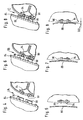
- eine vergrößerte Schnittansicht von Detail X aus
Figur 1 bei der Annäherung einander zugeordneter elektrischer Verbindungs- elemente des Bodenbearbeitungssystems; - Figur 5:
- eine Ansicht in Richtung von Pfeil A aus
Figur 4 ; - Figur 6:
- eine vergrößerte Schnittansicht von Detail X aus
Figur 1 beim Zusammentreffen der einander zugeordneten elektrischen Ver- bindungselemente; - Figur 7:
- eine Ansicht in Richtung von Pfeil B aus
Figur 6 ; - Figur 8:
- eine vergrößerte Schnittansicht von Detail X aus
Figur 1 nach Durchlaufen eines Federweges der einander zugeordneten elektrischen Verbindungselemente und - Figur 9:
- eine Ansicht in Richtung von Pfeil C aus
Figur 8 . - In der Zeichnung ist ein erfindungsgemäßes Bodenbearbeitungssystem in Form eines insgesamt mit dem Bezugszeichen 10 belegten Bodenreinigungssystems dargestellt, das eine zentrale Ladestation 12 sowie eine selbstfahrende und selbststeuernde Bodenbearbeitungseinheit in Form eines mobilen Sauggeräts 14 umfaßt.
- Das Sauggerät 14 ist als mobiler Reinigungsroboter ausgebildet und weist ein Gehäuse 16 mit einer Deckenwand 18 und einer Bodenwand 20 auf, die zwischen sich einen Saugkanal 22 definieren. In seinem rückwärtigen Bereich trägt das Gehäuse 16 eine von einem elektrischen Antriebsmotor 24 drehend angetriebene Saugturbine 26, die über einen Ansaugstutzen 28 mit dem Saugkanal 22 in Strömungsverbindung steht.
- Die Bodenwand 20 weist in ihrem vorderen, der Saugturbine 26 abgewandten Bereich einen Saugeinlaß 30 auf, der von Kehrbürsten 32 einer drehend antreibbaren Bürstenwalze 34 durchgriffen ist. Innerhalb des Saugkanals 22 ist ein Schmutzfilter 36 angeordnet, und der Bereich zwischen der Bürstenwalze 34 und dem Schmutzfilter 36 bildet einen Schmutzsammelbehälter 38. Zur Reinigung der Bodenfläche wird von der Saugturbine 26 eine Saugströmung erzeugt, mit deren Hilfe Schmutz von der Bodenfläche durch den Saugeinlaß 30 hindurch in den Schmutzsammelbehälter 38 überführt werden kann. Die Schmutzaufnahme von der Bodenfläche wird hierbei durch die Bürstenwalze 34 unterstützt.
- Das Gehäuse 16 bildet ein Fahrwerk des mobilen Sauggeräts 14 aus, an dem in an sich bekannter und deshalb in der Zeichnung nicht dargestellter Weise zwei Antriebsräder 40 drehbar gelagert sind, denen jeweils ein an sich bekannter Antriebsmotor (nicht dargestellt) zugeordnet ist.
- Wie aus
Figur 1 deutlich wird, ist das Gehäuse 16 in Umfangsrichtung von einem federnd am Gehäuse 16 gelagerten Tastring 42 umgeben, auf den ein Deckel 44 aufgesetzt ist. Zur Erzielung einer besseren Übersichtlichkeit sind der Tastring 42 und der Deckel 44 inFigur 2 nicht dargestellt. - Die Deckenwand 18 trägt eine wiederaufladbare Energieversorgungseinheit in Form einer wiederaufladbaren Batterie 46 und nimmt zusätzlich eine elektrische Steuerung 48 auf sowie jeweils im Bereich oberhalb eines Antriebsrades 40 zwei infrarotlichtempfindliche Sensoren 50 und einen Hallsensor 52. Mittels des Hallsensors 52 kann eine Relativbewegung des auf dem Tastring 42 aufsitzenden Deckels 44 bezogen auf das Gehäuse 16 erkannt werden. Tritt eine derartige Relativbewegung auf, so wird vom Hallsensor 52 ein Kollisionserkennungssignal an die Steuerung 48 übermittelt. Eine derartige Relativbewegung tritt beim Auftreffen des Sauggeräts 14 auf ein Hindernis auf. Aufgrund des Kollisionserkennungssignals kann dann die Fahrtrichtung des Sauggeräts 14 verändert werden, insbesondere kann eine Richtungsumkehr erfolgen.
- Mittels der beiden oberhalb der Antriebsräder 40 angeordneten infrarotlichtempfindlichen Sensoren 50 kann eine von der Ladestation 12 ausgesandte Zielstrahlung empfangen werden, so daß bei Unterschreiten eines vorgegebenen Grenzwertes des Ladezustands der Batterie 46 das Sauggerät 14 selbsttätig die Ladestation 12 anfahren kann zum Wiederaufladen der Batterie 46.
- Die Ladestation weist ein Gehäuse 54 auf, das ein Absaugaggregat 56 sowie einen Schmutzaufnahmebehälter 58 umgibt, der vom Absaugaggregat 56 mit Unterdruck beaufschlagt werden kann.
- Seitlich ist am Gehäuse 56 ein Ausleger 60 gehalten, der an seinem freien Ende vier infrarotlichtemittierende Dioden 62, 63, 64, 65 trägt. Unterhalb und im Abstand zum Ausleger 60 ist an das Gehäuse 54 der Ladestation 12 eine Rampe 66 angeformt, die eine Absaugöffnung 68 aufweist. An die Absaugöffnung 68 schließt sich ein Absaugkanal 70 an, der eine Strömungsverbindung ausbildet zwischen der Absaugöffnung 68 und dem Schmutzaufnahmebehälter 58.
- Der Ausleger 60 weist auf seiner der Rampe 66 zugewandten Unterseite eine stufig ausgebildete Tragplatte 72 auf mit einem dem Gehäuse 54 zugewandten hinteren Tragplattenabschnitt 74 und einem dem Gehäuse 54 abgewandten vorderen Tragplattenabschnitt 76, die über eine Stufe 78 einstückig miteinander verbunden sind. An der Stufe 78 ist eine weitere infrarotlichtemittierende Diode 80 angeordnet. Von den infrarotlichtemittierenden Dioden 62, 63, 64, 65 und 80 wird eine infrarote Zielstrahlung ausgesandt, die von den infrarotlichtempfindlichen Sensoren 50 des Sauggeräts 14 richtungsabhängig erfaßt wird und mit deren Hilfe das Sauggerät 14 selbsttätig die Ladestation 12 ansteuern kann. Das Sauggerät 14 fährt hierbei beim Andocken an die Ladestation 12 auf die Rampe 66, so daß der Saugeinlaß 30 fluchtend zur Absaugöffnung 68 ausgerichtet ist. Durch Ausbildung einer in
Figur 2 durch die Pfeile 82 symbolisierten Absaugströmung kann dann Schmutz aus dem Schmutzsammelbehälter 38 des mobilen Sauggeräts 14 über den Saugeinlaß 30 in den Schmutzaufnahmebehälter 58 der Ladestation 12 überführt werden. Gleichzeitig wird die Batterie 46 des Sauggeräts 14 wieder aufgeladen. Hierzu sind an einer den hinteren Tragplattenabschnitt 74 des Auslegers 60 mit der Rampe 66 verbindenden Stützwand 84 zwei elektrische Verbindungselemente in Form zweier Blattfedern 86, 88 gehalten, wobei die Federn zwischen zwei an der Stützwand 84 festgelegten Stützelementen 90, 92 eingespannt sind. Die beiden vorgespannten und konvex gekrümmten Blattfedern 86 und 88 sind über in der Zeichnung nicht dargestellte Anschlußleitungen mit einem Pluspol bzw. dem Minuspol einer an sich bekannten und deshalb in der Zeichnung nicht dargestellten elektrischen Spannungsquelle der Ladestation 12 verbunden. Die Spannungsquelle ist mittels eines an sich bekannten Netzkabels an die Netzspannung anschließbar. - Den beiden Blattfedern 86 und 88 sind jeweils zwei am Deckel 44 des Sauggeräts 14 starr gehaltene elektrische Kontaktstifte zugeordnet. Ein erster Kontaktstift 94 und ein zweiter Kontaktstift 96 wirken hierbei mit der Blattfeder 86 zusammen, und ein unterhalb des ersten Kontaktstiftes 94 positionierter dritter Kontaktstift 98 sowie ein unterhalb des zweiten Kontaktstiftes 96 angeordneter vierter Kontaktstift (in der Zeichnung nicht dargestellt) wirken mit der Blattfeder 88 zusammen. Dies wird insbesondere aus den
Figuren 4 und 5 deutlich. Treffen die Kontaktstifte auf die beiden Blattfedern 86 und 88, wie dies in denFiguren 6 und 7 dargestellt ist, so kann von der Ladestation 12 elektrische Energie zum Sauggerät 14 übertragen werden, indem über die Blattfedern 86, 88 und die Kontaktstifte ein Ladestrom zur Batterie 46 fließt. - Wie aus den
Figuren 8 und 9 deutlich wird, führt eine weitere Annäherung des Sauggeräts 14 an die Ladestation 12 dazu, daß die beiden Blattfedern 86 und 88 aufgrund ihrer Elastizität eine Ausweichbewegung entlang eines inFigur 9 dargestellten Federweges 102 ausführen. Die Federkonstante der beiden Blattfedern 86 und 88 ist hierbei geringer gewählt als die Federkonstante der federnden Halterung des Tastrings 42. Dies stellt sicher, daß die Blattfedern 86 und 88 zunächst eine federelastische Ausweichbewegung ausführen können und ein Ladestrom fließen kann, bevor vom Hallsensor 52 ein Kollisionserkennungssignal aufgrund einer Relativbewegung des Deckels 44 und des Tastrings 42 bezogen auf das Gehäuse 16 bereitgestellt wird. Demzufolge wird beim Auftreffen des Sauggeräts 14 auf die Ladestation 12 von der Steuerung 48 zunächst das Fließen eines Ladestromes zur Batterie 46 erkannt, so daß ein anschließend sich einstellendes Kollisionserkennungssignal so lange unterdrückt werden kann, bis der Ladevorgang beendet ist. Anschließend wird das Kollisionserkennungssignal freigegeben, so daß das Sauggerät 14 eine Fahrtrichtungsumkehr durchführt und sich nunmehr in die der Ladestation 12 abgewandte Richtung bewegt. Damit ist das Wiederaufladen der Batterie 46 und das gleichzeitige Absaugen des Schmutzsammelbehälters 38 beendet und das Sauggerät 14 kann seinen Normalbetrieb zum Reinigen der Bodenfläche wieder aufnehmen.
Claims (16)
- Bodenbearbeitungssystem (10) mit einer selbstfahrenden und selbststeuernden Bodenbearbeitungseinheit (14), die ein elektrisch angetriebenes Bodenbearbeitungsaggregat (24, 26) sowie eine wiederaufladbare Energieversorgungseinheit (46) umfaßt, und mit einer zentralen Ladestation (12) zum Wiederaufladen der Energieversorgungseinheit (46), wobei die Bodenbearbeitungseinheit (14) über einander zugeordnete elektrische Verbindungselemente (86, 88, 94, 96, 98), die an der Ladestation (12) und der Bodenbearbeitungseinheit (14) angeordnet sind, mit der Ladestation (12) elektrisch verbindbar ist und zumindest eines der einander zugeordneten Verbindungselemente (86, 88) federnd gehalten ist, dadurch gekennzeichnet, daß die Bodenbearbeitungseinheit (14) einen Kollisionserkennungssensor (52) umfaßt, dem ein federnd gehaltenes Tastelement (42, 44) zugeordnet ist, dessen Bewegung relativ zu einem Fahrwerk (16) der Bodenbearbeitungseinheit (14) zur Bereitstellung eines Kollisionserkennungssignals erfaßbar ist, wobei die federnde Halterung des mindestens einen elektrischen Verbindungselementes (86, 88) eine geringere Federkonstante aufweist als die federnde Halterung des Tastelements (42, 44).
- Bodenbearbeitungssystem nach Anspruch 1, dadurch gekennzeichnet, daß die einander zugeordneten Verbindungselemente elektrische Kontaktelemente (86, 88, 94, 96, 98) ausbilden zur ohmschen Kopplung der Bodenbearbeitungseinheit (14) mit der Ladestation (12).
- Bodenbearbeitungssystem nach Anspruch 1 oder 2, dadurch gekennzeichnet, daß das Bodenbearbeitungssystem (10) zumindest zwei erste Verbindungselemente (86, 88) aufweist, denen jeweils mindestens ein zweites Verbindungselement (94, 96; 98) zugeordnet ist.
- Bodenbearbeitungssystem nach Anspruch 3, dadurch gekennzeichnet, daß die ersten Verbindungselemente (86, 88) in vertikalem Abstand zueinander angeordnet sind.
- Bodenbearbeitungssystem nach einem der voranstehenden Ansprüche, dadurch gekennzeichnet, daß mindestens einem ersten Verbindungselement (86, 88) mehrere, im Abstand zueinander angeordnete zweite Verbindungselemente (94, 96; 98) zugeordnet sind.
- Bodenbearbeitungssystem nach Anspruch 5, dadurch gekennzeichnet, daß in Abhängigkeit von der Ausrichtung der Bodenbearbeitungseinheit (14) relativ zur Ladestation (12) eines oder mehrere der zweiten Verbindungselemente (94, 96; 98) mit dem zugeordneten ersten Verbindungselement (86, 88) elektrisch verbindbar sind.
- Bodenbearbeitungssystem nach Anspruch 5 oder 6, dadurch gekennzeichnet, daß die jeweils einem ersten Verbindungselement (86, 88) zugeordneten zweiten Verbindungselemente (94, 96; 98) in einer Ebene angeordnet sind.
- Bodenbearbeitungssystem nach einem der voranstehenden Ansprüche, dadurch gekennzeichnet, daß zumindest eines der einander zugeordneten Verbindungselemente (86, 88) flächig ausgestaltet ist.
- Bodenbearbeitungssystem nach Anspruch 8, dadurch gekennzeichnet, daß das mindestens eine flächige Verbindungselement (86, 88) streifenförmig ausgebildet ist.
- Bodenbearbeitungssystem nach Anspruch 8 oder 9, dadurch gekennzeichnet, daß das flächige Verbindungselement (86, 88) federnd gehalten ist.
- Bodenbearbeitungssystem nach Anspruch 8, 9 oder 10, dadurch gekennzeichnet, daß das flächig ausgestaltete Verbindungselement (86, 88) eine Blattfeder ausbildet.
- Bodenbearbeitungssystem nach einem der Ansprüche 8 bis 11, dadurch gekennzeichnet, daß das flächig ausgestaltete Verbindungselement. (86, 88) an der Ladestation (12) angeordnet ist.
- Bodenbearbeitungssystem nach einem der Ansprüche 8 bis 12, dadurch gekennzeichnet, daß dem flächig ausgestalteten Verbindungselement (86, 88) mehrere Kontaktstifte (94, 96; 98) zugeordnet sind.
- Bodenbearbeitungssystem nach einem der voranstehenden Ansprüche, dadurch gekennzeichnet, daß an der Ladestation (12) zwei horizontal ausgerichtete, blattfederartige Verbindungselemente (86, 88) übereinander angeordnet sind, denen jeweils mindestens zwei an der Bodenbearbeitungseinheit gehaltene Kontaktstifte (94, 96; 98) zugeordnet sind.
- Bodenbearbeitungssystem nach einem der voranstehenden Ansprüche,
dadurch gekennzeichnet, daß die Bodenbearbeitungseinheit ein mobiles Sauggerät (14) ausbildet mit einer Saugturbine (26) und einem einen Saugeinlaß (30) aufweisenden Schmutzsammelbehälter (38). - Bodenbearbeitungssystem nach Anspruch 15, dadurch gekennzeichnet, daß die Ladestation (12) ein Absaugaggregat (56) umfaßt sowie einen Schmutzaufnahmebehälter (58), wobei beim Wiederaufladen der Energieversorgungseinheit (46) gleichzeitig der Schmutzsammelbehälter (38) über den Saugeinlaß (30) vom Absaugaggregat (56) absaugbar ist.
Applications Claiming Priority (3)
| Application Number | Priority Date | Filing Date | Title |
|---|---|---|---|
| DE10231388A DE10231388A1 (de) | 2002-07-08 | 2002-07-08 | Bodenbearbeitungssystem |
| DE10231388 | 2002-07-08 | ||
| PCT/EP2003/006224 WO2004004534A1 (de) | 2002-07-08 | 2003-06-13 | Bodenbearbeitungssystem |
Publications (2)
| Publication Number | Publication Date |
|---|---|
| EP1519672A1 EP1519672A1 (de) | 2005-04-06 |
| EP1519672B1 true EP1519672B1 (de) | 2011-08-10 |
Family
ID=30009909
Family Applications (1)
| Application Number | Title | Priority Date | Filing Date |
|---|---|---|---|
| EP03735619A Expired - Lifetime EP1519672B1 (de) | 2002-07-08 | 2003-06-13 | Bodenbearbeitungssystem |
Country Status (6)
| Country | Link |
|---|---|
| US (1) | US7055210B2 (de) |
| EP (1) | EP1519672B1 (de) |
| AT (1) | ATE519408T1 (de) |
| AU (1) | AU2003237938A1 (de) |
| DE (1) | DE10231388A1 (de) |
| WO (1) | WO2004004534A1 (de) |
Cited By (1)
| Publication number | Priority date | Publication date | Assignee | Title |
|---|---|---|---|---|
| CN110911904A (zh) * | 2019-11-15 | 2020-03-24 | 深圳市优必选科技股份有限公司 | 第一电源结构、第二电源结构、充电装置及机器人系统 |
Families Citing this family (128)
| Publication number | Priority date | Publication date | Assignee | Title |
|---|---|---|---|---|
| US8412377B2 (en) | 2000-01-24 | 2013-04-02 | Irobot Corporation | Obstacle following sensor scheme for a mobile robot |
| US8788092B2 (en) | 2000-01-24 | 2014-07-22 | Irobot Corporation | Obstacle following sensor scheme for a mobile robot |
| US6956348B2 (en) | 2004-01-28 | 2005-10-18 | Irobot Corporation | Debris sensor for cleaning apparatus |
| US6690134B1 (en) | 2001-01-24 | 2004-02-10 | Irobot Corporation | Method and system for robot localization and confinement |
| US7571511B2 (en) | 2002-01-03 | 2009-08-11 | Irobot Corporation | Autonomous floor-cleaning robot |
| US8396592B2 (en) | 2001-06-12 | 2013-03-12 | Irobot Corporation | Method and system for multi-mode coverage for an autonomous robot |
| US7663333B2 (en) | 2001-06-12 | 2010-02-16 | Irobot Corporation | Method and system for multi-mode coverage for an autonomous robot |
| US9128486B2 (en) | 2002-01-24 | 2015-09-08 | Irobot Corporation | Navigational control system for a robotic device |
| US20040162637A1 (en) | 2002-07-25 | 2004-08-19 | Yulun Wang | Medical tele-robotic system with a master remote station with an arbitrator |
| US8386081B2 (en) | 2002-09-13 | 2013-02-26 | Irobot Corporation | Navigational control system for a robotic device |
| US8428778B2 (en) | 2002-09-13 | 2013-04-23 | Irobot Corporation | Navigational control system for a robotic device |
| US7813836B2 (en) | 2003-12-09 | 2010-10-12 | Intouch Technologies, Inc. | Protocol for a remotely controlled videoconferencing robot |
| US7332890B2 (en) | 2004-01-21 | 2008-02-19 | Irobot Corporation | Autonomous robot auto-docking and energy management systems and methods |
| JP2007530978A (ja) | 2004-03-29 | 2007-11-01 | エヴォリューション ロボティクス インコーポレイテッド | 反射光源を使用する位置推定方法および装置 |
| EP1776623B1 (de) | 2004-06-24 | 2011-12-07 | iRobot Corporation | Fernbediente ablaufsteuerung und verfahren für eine autonome robotervorrichtung |
| US8972052B2 (en) | 2004-07-07 | 2015-03-03 | Irobot Corporation | Celestial navigation system for an autonomous vehicle |
| US7706917B1 (en) | 2004-07-07 | 2010-04-27 | Irobot Corporation | Celestial navigation system for an autonomous robot |
| US8077963B2 (en) | 2004-07-13 | 2011-12-13 | Yulun Wang | Mobile robot with a head-based movement mapping scheme |
| US8392021B2 (en) | 2005-02-18 | 2013-03-05 | Irobot Corporation | Autonomous surface cleaning robot for wet cleaning |
| US7620476B2 (en) | 2005-02-18 | 2009-11-17 | Irobot Corporation | Autonomous surface cleaning robot for dry cleaning |
| EP1850725B1 (de) | 2005-02-18 | 2010-05-19 | iRobot Corporation | Autonomer oberflächenreinigungsroboter für nass- und trockenreinigung |
| ES2238196B1 (es) * | 2005-03-07 | 2006-11-16 | Electrodomesticos Taurus, S.L. | Estacion base con robot aspirador. |
| JP4782684B2 (ja) * | 2005-03-25 | 2011-09-28 | 株式会社東芝 | 電気掃除機 |
| US8930023B2 (en) | 2009-11-06 | 2015-01-06 | Irobot Corporation | Localization by learning of wave-signal distributions |
| US9198728B2 (en) | 2005-09-30 | 2015-12-01 | Intouch Technologies, Inc. | Multi-camera mobile teleconferencing platform |
| KR100692897B1 (ko) * | 2005-10-28 | 2007-03-12 | 엘지전자 주식회사 | 이동로봇 |
| US8374721B2 (en) | 2005-12-02 | 2013-02-12 | Irobot Corporation | Robot system |
| ES2522926T3 (es) | 2005-12-02 | 2014-11-19 | Irobot Corporation | Robot Autónomo de Cubrimiento |
| US7441298B2 (en) | 2005-12-02 | 2008-10-28 | Irobot Corporation | Coverage robot mobility |
| EP2816434A3 (de) * | 2005-12-02 | 2015-01-28 | iRobot Corporation | Roboter mit autonomem Wirkungsbereich |
| US8584305B2 (en) | 2005-12-02 | 2013-11-19 | Irobot Corporation | Modular robot |
| KR20070074146A (ko) * | 2006-01-06 | 2007-07-12 | 삼성전자주식회사 | 청소기 시스템 |
| EP2394553B1 (de) | 2006-05-19 | 2016-04-20 | iRobot Corporation | Müllentfernung aus Reinigungsrobotern |
| US8417383B2 (en) | 2006-05-31 | 2013-04-09 | Irobot Corporation | Detecting robot stasis |
| US8849679B2 (en) | 2006-06-15 | 2014-09-30 | Intouch Technologies, Inc. | Remote controlled robot system that provides medical images |
| US7877839B2 (en) * | 2006-11-20 | 2011-02-01 | Black & Decker Inc. | Wet and/or dry vacuum with floor collector |
| KR101414321B1 (ko) | 2007-05-09 | 2014-07-01 | 아이로보트 코퍼레이션 | 자동 커버리지 로봇 |
| US9160783B2 (en) | 2007-05-09 | 2015-10-13 | Intouch Technologies, Inc. | Robot system that operates through a network firewall |
| DE102007036228B4 (de) | 2007-08-02 | 2013-10-10 | BSH Bosch und Siemens Hausgeräte GmbH | Verfahren und System zur Sicherstellung einer Verbindung zwischen einem mobilen Gerät und einem stationären Gerät, insbesondere zwischen einem akkumulatorbetriebenen Staubsammelroboter und einer Akkumulator-Ladestation |
| DE102007036173B4 (de) | 2007-08-02 | 2012-01-26 | BSH Bosch und Siemens Hausgeräte GmbH | Gehäuse für eine Feststation eines insbesondere durch ein Staubsammelrobotersystem gebildeten Robotersystems |
| DE102007036172B4 (de) | 2007-08-02 | 2012-01-19 | BSH Bosch und Siemens Hausgeräte GmbH | Gehäuse für eine Feststation eines insbesondere durch ein Staubsammelrobotersystem gebildeten Robotersystems |
| DE102007036152B4 (de) | 2007-08-02 | 2011-06-16 | BSH Bosch und Siemens Hausgeräte GmbH | Gehäuse für eine Feststation eines insbesondere durch ein Staubsammelrobotersystem gebildeten Robotersystems |
| US10875182B2 (en) | 2008-03-20 | 2020-12-29 | Teladoc Health, Inc. | Remote presence system mounted to operating room hardware |
| US8179418B2 (en) | 2008-04-14 | 2012-05-15 | Intouch Technologies, Inc. | Robotic based health care system |
| US8170241B2 (en) | 2008-04-17 | 2012-05-01 | Intouch Technologies, Inc. | Mobile tele-presence system with a microphone system |
| US8452450B2 (en) * | 2008-04-24 | 2013-05-28 | Evolution Robotics, Inc. | Application of localization, positioning and navigation systems for robotic enabled mobile products |
| US9193065B2 (en) * | 2008-07-10 | 2015-11-24 | Intouch Technologies, Inc. | Docking system for a tele-presence robot |
| US9842192B2 (en) | 2008-07-11 | 2017-12-12 | Intouch Technologies, Inc. | Tele-presence robot system with multi-cast features |
| US8340819B2 (en) | 2008-09-18 | 2012-12-25 | Intouch Technologies, Inc. | Mobile videoconferencing robot system with network adaptive driving |
| US8996165B2 (en) | 2008-10-21 | 2015-03-31 | Intouch Technologies, Inc. | Telepresence robot with a camera boom |
| US8463435B2 (en) | 2008-11-25 | 2013-06-11 | Intouch Technologies, Inc. | Server connectivity control for tele-presence robot |
| US9138891B2 (en) | 2008-11-25 | 2015-09-22 | Intouch Technologies, Inc. | Server connectivity control for tele-presence robot |
| US8849680B2 (en) | 2009-01-29 | 2014-09-30 | Intouch Technologies, Inc. | Documentation through a remote presence robot |
| US8897920B2 (en) | 2009-04-17 | 2014-11-25 | Intouch Technologies, Inc. | Tele-presence robot system with software modularity, projector and laser pointer |
| GB2484629B (en) * | 2009-07-01 | 2014-01-15 | Racine Ind Inc | Combination of carpet-cleaning machine and platform for transporting the machine |
| US11399153B2 (en) | 2009-08-26 | 2022-07-26 | Teladoc Health, Inc. | Portable telepresence apparatus |
| US8384755B2 (en) | 2009-08-26 | 2013-02-26 | Intouch Technologies, Inc. | Portable remote presence robot |
| CN101992190B (zh) * | 2009-08-28 | 2016-04-06 | 科沃斯机器人有限公司 | 地面处理系统及其脏物清扫和清空方法 |
| US11154981B2 (en) | 2010-02-04 | 2021-10-26 | Teladoc Health, Inc. | Robot user interface for telepresence robot system |
| KR101497197B1 (ko) | 2010-02-16 | 2015-02-27 | 아이로보트 코퍼레이션 | 진공 브러쉬 |
| US8670017B2 (en) | 2010-03-04 | 2014-03-11 | Intouch Technologies, Inc. | Remote presence system including a cart that supports a robot face and an overhead camera |
| CN102217910B (zh) * | 2010-04-14 | 2014-06-25 | 泰怡凯电器(苏州)有限公司 | 地面处理系统 |
| CN102217918A (zh) * | 2010-04-14 | 2011-10-19 | 泰怡凯电器(苏州)有限公司 | 机器人系统及其机器人与充电座的对接方法 |
| CN102217914B (zh) * | 2010-04-14 | 2015-05-27 | 科沃斯机器人有限公司 | 机器人系统 |
| WO2011145989A1 (en) * | 2010-05-19 | 2011-11-24 | Husqvarna Ab | Effective charging by multiple contact points |
| US10343283B2 (en) | 2010-05-24 | 2019-07-09 | Intouch Technologies, Inc. | Telepresence robot system that can be accessed by a cellular phone |
| US10808882B2 (en) | 2010-05-26 | 2020-10-20 | Intouch Technologies, Inc. | Tele-robotic system with a robot face placed on a chair |
| KR101483541B1 (ko) * | 2010-07-15 | 2015-01-19 | 삼성전자주식회사 | 로봇청소기, 메인터넌스 스테이션 그리고 이들을 가지는 청소시스템 |
| RU2430672C1 (ru) * | 2010-09-14 | 2011-10-10 | Общество С Ограниченной Ответственностью Компания "Норкпалм" | Автоматическая система уборки помещения с парковочным модулем для робота-пылесоса |
| WO2012036586A1 (ru) * | 2010-09-14 | 2012-03-22 | Общество С Ограниченной Ответственностью Компания "Норкпалм" | Автоматическая система уборки помещения |
| CN102407522B (zh) * | 2010-09-19 | 2014-03-26 | 泰怡凯电器(苏州)有限公司 | 智能机器人系统及其充电对接方法 |
| US9264664B2 (en) | 2010-12-03 | 2016-02-16 | Intouch Technologies, Inc. | Systems and methods for dynamic bandwidth allocation |
| US12093036B2 (en) | 2011-01-21 | 2024-09-17 | Teladoc Health, Inc. | Telerobotic system with a dual application screen presentation |
| CN103459099B (zh) | 2011-01-28 | 2015-08-26 | 英塔茨科技公司 | 与一个可移动的远程机器人相互交流 |
| US9323250B2 (en) | 2011-01-28 | 2016-04-26 | Intouch Technologies, Inc. | Time-dependent navigation of telepresence robots |
| US11482326B2 (en) | 2011-02-16 | 2022-10-25 | Teladog Health, Inc. | Systems and methods for network-based counseling |
| US10769739B2 (en) | 2011-04-25 | 2020-09-08 | Intouch Technologies, Inc. | Systems and methods for management of information among medical providers and facilities |
| US9098611B2 (en) | 2012-11-26 | 2015-08-04 | Intouch Technologies, Inc. | Enhanced video interaction for a user interface of a telepresence network |
| US20140139616A1 (en) | 2012-01-27 | 2014-05-22 | Intouch Technologies, Inc. | Enhanced Diagnostics for a Telepresence Robot |
| US8836751B2 (en) | 2011-11-08 | 2014-09-16 | Intouch Technologies, Inc. | Tele-presence system with a user interface that displays different communication links |
| EP2797401B1 (de) * | 2011-12-30 | 2018-01-31 | Husqvarna AB | Kontaktanordnung einer ladevorrichtung eines robotischen gartenwerkzeugs |
| US9251313B2 (en) | 2012-04-11 | 2016-02-02 | Intouch Technologies, Inc. | Systems and methods for visualizing and managing telepresence devices in healthcare networks |
| US8902278B2 (en) | 2012-04-11 | 2014-12-02 | Intouch Technologies, Inc. | Systems and methods for visualizing and managing telepresence devices in healthcare networks |
| EP2852881A4 (de) | 2012-05-22 | 2016-03-23 | Intouch Technologies Inc | Grafische benutzerschnittstellen mit touchpad -ansteuerungsschnittstellen für telemedizinische vorrichtungen |
| US9361021B2 (en) | 2012-05-22 | 2016-06-07 | Irobot Corporation | Graphical user interfaces including touchpad driving interfaces for telemedicine devices |
| CN105559703B (zh) * | 2014-11-10 | 2018-01-30 | 江苏美的清洁电器股份有限公司 | 充电座及具有其的扫地机器人 |
| US9788698B2 (en) * | 2014-12-10 | 2017-10-17 | Irobot Corporation | Debris evacuation for cleaning robots |
| USD760649S1 (en) | 2015-06-22 | 2016-07-05 | Mtd Products Inc | Docking station |
| US9462920B1 (en) | 2015-06-25 | 2016-10-11 | Irobot Corporation | Evacuation station |
| KR102626404B1 (ko) * | 2016-05-09 | 2024-01-18 | 엘지전자 주식회사 | 청소기의 충전대 및 청소기의 거치대 |
| WO2017195999A1 (ko) | 2016-05-09 | 2017-11-16 | 엘지전자 주식회사 | 청소기 거치대 |
| WO2017196000A1 (ko) * | 2016-05-09 | 2017-11-16 | 엘지전자 주식회사 | 청소기 거치대 |
| TWI687194B (zh) * | 2016-07-14 | 2020-03-11 | 南韓商Lg電子股份有限公司 | 清掃機器人及其維護裝置 |
| FR3059479B1 (fr) * | 2016-11-28 | 2019-03-15 | Commissariat A L'energie Atomique Et Aux Energies Alternatives | Systeme de raccordement electrique securise |
| US11794141B2 (en) * | 2021-01-25 | 2023-10-24 | Omachron Intellectual Property Inc. | Multiuse home station |
| US11862302B2 (en) | 2017-04-24 | 2024-01-02 | Teladoc Health, Inc. | Automated transcription and documentation of tele-health encounters |
| US10483007B2 (en) | 2017-07-25 | 2019-11-19 | Intouch Technologies, Inc. | Modular telehealth cart with thermal imaging and touch screen user interface |
| US11636944B2 (en) | 2017-08-25 | 2023-04-25 | Teladoc Health, Inc. | Connectivity infrastructure for a telehealth platform |
| USD867987S1 (en) * | 2017-09-15 | 2019-11-26 | Beijing Rockrobo Technology Co., Ltd. | Base station |
| DE102017125964A1 (de) * | 2017-11-07 | 2019-05-09 | Miele & Cie. Kg | Ladevorrichtung für Haushaltsgerät und Haushaltsgerät |
| WO2019104668A1 (zh) * | 2017-11-30 | 2019-06-06 | 深圳市沃特沃德股份有限公司 | 垃圾回收装置及扫地系统 |
| CN107997686A (zh) * | 2017-11-30 | 2018-05-08 | 深圳市沃特沃德股份有限公司 | 垃圾回收装置及扫地系统 |
| US10617299B2 (en) | 2018-04-27 | 2020-04-14 | Intouch Technologies, Inc. | Telehealth cart that supports a removable tablet with seamless audio/video switching |
| US10595696B2 (en) | 2018-05-01 | 2020-03-24 | Sharkninja Operating Llc | Docking station for robotic cleaner |
| US10842334B2 (en) | 2018-05-04 | 2020-11-24 | Irobot Corporation | Filtering devices for evacuation stations |
| USD908992S1 (en) | 2018-05-04 | 2021-01-26 | Irobot Corporation | Evacuation station |
| USD908993S1 (en) | 2018-05-04 | 2021-01-26 | Irobot Corporation | Evacuation station |
| USD890231S1 (en) | 2018-05-04 | 2020-07-14 | Irobot Corporation | Debris container |
| USD893562S1 (en) | 2018-05-04 | 2020-08-18 | Irobot Corporation | Debris container |
| USD893561S1 (en) | 2018-05-04 | 2020-08-18 | Irobot Corporation | Debris container |
| USD930053S1 (en) | 2018-05-04 | 2021-09-07 | Irobot Corporation | Debris container |
| USD924522S1 (en) | 2018-05-04 | 2021-07-06 | Irobot Corporation | Evacuation station |
| EP3823507B1 (de) | 2018-07-20 | 2025-04-16 | SharkNinja Operating LLC | Andockstation für ablagerungsentfernung bei einem reinigungsroboter |
| CN109480714B (zh) * | 2018-12-25 | 2023-10-03 | 北京享捷科技有限公司 | 一种扫地机器人吸尘充电装置以及吸尘充电方法 |
| CN109659745B (zh) * | 2018-12-29 | 2020-09-11 | 深圳市优必选科技有限公司 | 电极触点结构及机器人充电桩 |
| UA41384S (uk) * | 2019-03-18 | 2020-04-27 | Бейцзін Сяомі Мо | Зарядне пристосування для прибирального пристрою |
| USD951859S1 (en) * | 2019-08-15 | 2022-05-17 | Beijing Xiaomi Mobile Software Co., Ltd. | Charging base for robot vacuum cleaner |
| DE102019122060A1 (de) * | 2019-08-16 | 2021-02-18 | Vorwerk & Co. Interholding Gmbh | Basisstation zum stationären Entleeren eines Schmutzraumes eines mobilen Reinigungsgerätes, Reinigungssystem sowie Verfahren |
| CN110466918B (zh) * | 2019-08-21 | 2022-08-05 | 深圳市无限动力发展有限公司 | 垃圾回收站及清洁系统 |
| JP7780245B2 (ja) * | 2019-10-30 | 2025-12-04 | 東芝ライフスタイル株式会社 | 電気掃除装置 |
| CN111419119B (zh) * | 2020-03-13 | 2021-11-30 | 尚科宁家(中国)科技有限公司 | 一种清洁机器人的回充装置、系统及控制方法 |
| CN111449584B (zh) * | 2020-04-17 | 2021-10-08 | 深圳市无限动力发展有限公司 | 工作站及清洁设备 |
| KR20220000297A (ko) * | 2020-06-25 | 2022-01-03 | 삼성전자주식회사 | 도킹 스테이션, 이동 로봇 및 도킹 스테이션과 이동 로봇을 제어하는 이동 로봇 관리 시스템 |
| CN112956958A (zh) * | 2021-02-26 | 2021-06-15 | 美智纵横科技有限责任公司 | 一种清洁系统 |
| USD1032509S1 (en) | 2021-04-23 | 2024-06-25 | Mtd Products Inc | Docking station |
| USD989983S1 (en) * | 2022-06-13 | 2023-06-20 | Beijing Roborock Technology Co., Ltd. | Auxiliary obstacle-surmounting ramp for cleaning robot |
| USD1051177S1 (en) * | 2022-06-15 | 2024-11-12 | Husqvarna Ab | Mower house |
| USD1112375S1 (en) * | 2023-12-12 | 2026-02-10 | Shandong Jafirst Turing Robot Technology Co., Ltd | Lawn mower with charging device |
Family Cites Families (5)
| Publication number | Priority date | Publication date | Assignee | Title |
|---|---|---|---|---|
| FR2620070A2 (fr) * | 1986-12-11 | 1989-03-10 | Jonas Andre | Unite mobile autoguidee et appareil de nettoyage tel qu'un aspirateur comportant une telle unite |
| SE9302874L (sv) * | 1992-09-08 | 1994-03-09 | Gold Star Co | Anordning vid självgående dammsugare |
| US6076226A (en) * | 1997-01-27 | 2000-06-20 | Robert J. Schaap | Controlled self operated vacuum cleaning system |
| EP1049964B1 (de) * | 1997-11-27 | 2002-03-13 | Solar & Robotics | Verbesserungen bei beweglichen robotern und bei ihren steuerungssystemen |
| DE29824552U1 (de) * | 1998-01-08 | 2001-07-26 | Aktiebolaget Electrolux, Stockholm | Ankopplungssystem für ein selbstfahrendes Arbeitsgerät |
-
2002
- 2002-07-08 DE DE10231388A patent/DE10231388A1/de not_active Withdrawn
-
2003
- 2003-06-13 WO PCT/EP2003/006224 patent/WO2004004534A1/de not_active Ceased
- 2003-06-13 EP EP03735619A patent/EP1519672B1/de not_active Expired - Lifetime
- 2003-06-13 AU AU2003237938A patent/AU2003237938A1/en not_active Abandoned
- 2003-06-13 AT AT03735619T patent/ATE519408T1/de active
-
2005
- 2005-01-04 US US11/030,011 patent/US7055210B2/en not_active Expired - Lifetime
Cited By (2)
| Publication number | Priority date | Publication date | Assignee | Title |
|---|---|---|---|---|
| CN110911904A (zh) * | 2019-11-15 | 2020-03-24 | 深圳市优必选科技股份有限公司 | 第一电源结构、第二电源结构、充电装置及机器人系统 |
| CN110911904B (zh) * | 2019-11-15 | 2021-12-17 | 深圳市优必选科技股份有限公司 | 第一电源结构、第二电源结构、充电装置及机器人系统 |
Also Published As
| Publication number | Publication date |
|---|---|
| US7055210B2 (en) | 2006-06-06 |
| US20050166352A1 (en) | 2005-08-04 |
| AU2003237938A1 (en) | 2004-01-23 |
| ATE519408T1 (de) | 2011-08-15 |
| DE10231388A1 (de) | 2004-02-05 |
| EP1519672A1 (de) | 2005-04-06 |
| WO2004004534A1 (de) | 2004-01-15 |
Similar Documents
| Publication | Publication Date | Title |
|---|---|---|
| EP1519672B1 (de) | Bodenbearbeitungssystem | |
| EP1671195B1 (de) | Bodenbearbeitungssystem | |
| DE69804253T2 (de) | Verbesserungen bei beweglichen robotern und bei ihren steuerungssystemen | |
| DE102004041021B3 (de) | Bodenreinigungssystem | |
| DE10261787B3 (de) | Mobiles Bodenbearbeitungsgerät | |
| EP1366401B1 (de) | Bodenbearbeitungsgerät insbesondere bodenreinigungsgerät | |
| DE10319512B4 (de) | Automatisches Reinigungssystem mit einer externen Ladevorrichtung sowie Verfahren zum Andocken an der Ladevorrichtung | |
| DE102010044276B4 (de) | Schalteinrichtung für einen Rasenmäher | |
| EP2974640B2 (de) | Saugroboter mit rotierender borstwalze und reinigungsverfahren für eine borstwalze eines saugroboters | |
| EP3023045B1 (de) | Staubsaugerseitenbürste und bodenpflegegerät mit einer staubsaugerseitenbürste | |
| DE69808144T2 (de) | Ankopplungssystem fuer ein selbstfahrendes werkzeug | |
| DE102004004505B9 (de) | Bodenbearbeitungsgerät sowie Verfahren zu dessen Steuerung | |
| DE202009010809U1 (de) | Mobile Robotervorrichtung mit einem Aufprallsensor | |
| EP1967116A1 (de) | Verfahren zur Reinigung einer Bodenfläche mittels eines selbstfahrenden Reinigungsgerätes, insbesondere eines Robotsaugers | |
| DE10242257A1 (de) | Selbsttätig verfahrbares Bodenstaub-Aufsammelgerät, sowie Kombination eines derartigen Aufsammelgerätes und einer Basisstation | |
| DE4340771A1 (de) | Automatische Reinigungsvorrichtung | |
| EP3047777A2 (de) | Staubsaugerroboter | |
| DE202011051073U1 (de) | Reinigungsvorrichtung für Solarmodule | |
| DE202024103561U1 (de) | Getriebeeinrichtungen, automatische Reinigungsgeräte und Reinigungsrobotersysteme | |
| WO2020058525A1 (de) | Ladevorrichtung zum laden eines elektrofahrzeugs | |
| DE2948664A1 (de) | Landmaschine | |
| EP3440913B1 (de) | Sich selbsttätig fortbewegendes bodenbearbeitungsgerät | |
| EP3284381A2 (de) | Ladestation, insbesondere für ein reinigungsgerät | |
| EP2278907B1 (de) | Fahrbares kehrgerät | |
| DE102018116225A1 (de) | Reinigungsgerät |
Legal Events
| Date | Code | Title | Description |
|---|---|---|---|
| PUAI | Public reference made under article 153(3) epc to a published international application that has entered the european phase |
Free format text: ORIGINAL CODE: 0009012 |
|
| 17P | Request for examination filed |
Effective date: 20041217 |
|
| AK | Designated contracting states |
Kind code of ref document: A1 Designated state(s): AT BE BG CH CY CZ DE DK EE ES FI FR GB GR HU IE IT LI LU MC NL PT RO SE SI SK TR |
|
| AX | Request for extension of the european patent |
Extension state: AL LT LV MK |
|
| DAX | Request for extension of the european patent (deleted) | ||
| GRAP | Despatch of communication of intention to grant a patent |
Free format text: ORIGINAL CODE: EPIDOSNIGR1 |
|
| RIC1 | Information provided on ipc code assigned before grant |
Ipc: A47L 9/10 20060101ALI20110203BHEP Ipc: A47L 9/28 20060101ALI20110203BHEP Ipc: A47L 9/00 20060101AFI20110203BHEP |
|
| RIN1 | Information on inventor provided before grant (corrected) |
Inventor name: SKOUMAL, ROGER Inventor name: KEPPLER, JOACHIM Inventor name: MATH, JOCHEN |
|
| GRAS | Grant fee paid |
Free format text: ORIGINAL CODE: EPIDOSNIGR3 |
|
| GRAA | (expected) grant |
Free format text: ORIGINAL CODE: 0009210 |
|
| AK | Designated contracting states |
Kind code of ref document: B1 Designated state(s): AT BE BG CH CY CZ DE DK EE ES FI FR GB GR HU IE IT LI LU MC NL PT RO SE SI SK TR |
|
| REG | Reference to a national code |
Ref country code: GB Ref legal event code: FG4D Free format text: NOT ENGLISH |
|
| REG | Reference to a national code |
Ref country code: DE Ref legal event code: R081 Ref document number: 50313887 Country of ref document: DE Owner name: ALFRED KAERCHER SE & CO. KG, DE Free format text: FORMER OWNER: ALFRED KAERCHER GMBH & CO. KG, 71364 WINNENDEN, DE |
|
| REG | Reference to a national code |
Ref country code: CH Ref legal event code: NV Representative=s name: ISLER & PEDRAZZINI AG Ref country code: CH Ref legal event code: EP |
|
| REG | Reference to a national code |
Ref country code: IE Ref legal event code: FG4D Free format text: LANGUAGE OF EP DOCUMENT: GERMAN |
|
| REG | Reference to a national code |
Ref country code: DE Ref legal event code: R096 Ref document number: 50313887 Country of ref document: DE Effective date: 20111006 |
|
| REG | Reference to a national code |
Ref country code: NL Ref legal event code: T3 |
|
| PG25 | Lapsed in a contracting state [announced via postgrant information from national office to epo] |
Ref country code: FI Free format text: LAPSE BECAUSE OF FAILURE TO SUBMIT A TRANSLATION OF THE DESCRIPTION OR TO PAY THE FEE WITHIN THE PRESCRIBED TIME-LIMIT Effective date: 20110810 Ref country code: SE Free format text: LAPSE BECAUSE OF FAILURE TO SUBMIT A TRANSLATION OF THE DESCRIPTION OR TO PAY THE FEE WITHIN THE PRESCRIBED TIME-LIMIT Effective date: 20110810 Ref country code: PT Free format text: LAPSE BECAUSE OF FAILURE TO SUBMIT A TRANSLATION OF THE DESCRIPTION OR TO PAY THE FEE WITHIN THE PRESCRIBED TIME-LIMIT Effective date: 20111212 |
|
| PG25 | Lapsed in a contracting state [announced via postgrant information from national office to epo] |
Ref country code: GR Free format text: LAPSE BECAUSE OF FAILURE TO SUBMIT A TRANSLATION OF THE DESCRIPTION OR TO PAY THE FEE WITHIN THE PRESCRIBED TIME-LIMIT Effective date: 20111111 Ref country code: CY Free format text: LAPSE BECAUSE OF FAILURE TO SUBMIT A TRANSLATION OF THE DESCRIPTION OR TO PAY THE FEE WITHIN THE PRESCRIBED TIME-LIMIT Effective date: 20110810 Ref country code: SI Free format text: LAPSE BECAUSE OF FAILURE TO SUBMIT A TRANSLATION OF THE DESCRIPTION OR TO PAY THE FEE WITHIN THE PRESCRIBED TIME-LIMIT Effective date: 20110810 |
|
| REG | Reference to a national code |
Ref country code: IE Ref legal event code: FD4D |
|
| PG25 | Lapsed in a contracting state [announced via postgrant information from national office to epo] |
Ref country code: CZ Free format text: LAPSE BECAUSE OF FAILURE TO SUBMIT A TRANSLATION OF THE DESCRIPTION OR TO PAY THE FEE WITHIN THE PRESCRIBED TIME-LIMIT Effective date: 20110810 Ref country code: IE Free format text: LAPSE BECAUSE OF FAILURE TO SUBMIT A TRANSLATION OF THE DESCRIPTION OR TO PAY THE FEE WITHIN THE PRESCRIBED TIME-LIMIT Effective date: 20110810 Ref country code: SK Free format text: LAPSE BECAUSE OF FAILURE TO SUBMIT A TRANSLATION OF THE DESCRIPTION OR TO PAY THE FEE WITHIN THE PRESCRIBED TIME-LIMIT Effective date: 20110810 |
|
| PG25 | Lapsed in a contracting state [announced via postgrant information from national office to epo] |
Ref country code: EE Free format text: LAPSE BECAUSE OF FAILURE TO SUBMIT A TRANSLATION OF THE DESCRIPTION OR TO PAY THE FEE WITHIN THE PRESCRIBED TIME-LIMIT Effective date: 20110810 Ref country code: RO Free format text: LAPSE BECAUSE OF FAILURE TO SUBMIT A TRANSLATION OF THE DESCRIPTION OR TO PAY THE FEE WITHIN THE PRESCRIBED TIME-LIMIT Effective date: 20110810 |
|
| PLBE | No opposition filed within time limit |
Free format text: ORIGINAL CODE: 0009261 |
|
| STAA | Information on the status of an ep patent application or granted ep patent |
Free format text: STATUS: NO OPPOSITION FILED WITHIN TIME LIMIT |
|
| PG25 | Lapsed in a contracting state [announced via postgrant information from national office to epo] |
Ref country code: DK Free format text: LAPSE BECAUSE OF FAILURE TO SUBMIT A TRANSLATION OF THE DESCRIPTION OR TO PAY THE FEE WITHIN THE PRESCRIBED TIME-LIMIT Effective date: 20110810 |
|
| 26N | No opposition filed |
Effective date: 20120511 |
|
| REG | Reference to a national code |
Ref country code: DE Ref legal event code: R097 Ref document number: 50313887 Country of ref document: DE Effective date: 20120511 |
|
| BERE | Be: lapsed |
Owner name: ALFRED KARCHER G.M.B.H. & CO. KG Effective date: 20120630 |
|
| PG25 | Lapsed in a contracting state [announced via postgrant information from national office to epo] |
Ref country code: MC Free format text: LAPSE BECAUSE OF NON-PAYMENT OF DUE FEES Effective date: 20120630 |
|
| GBPC | Gb: european patent ceased through non-payment of renewal fee |
Effective date: 20120613 |
|
| REG | Reference to a national code |
Ref country code: FR Ref legal event code: ST Effective date: 20130228 |
|
| PG25 | Lapsed in a contracting state [announced via postgrant information from national office to epo] |
Ref country code: BE Free format text: LAPSE BECAUSE OF NON-PAYMENT OF DUE FEES Effective date: 20120630 Ref country code: GB Free format text: LAPSE BECAUSE OF NON-PAYMENT OF DUE FEES Effective date: 20120613 Ref country code: ES Free format text: LAPSE BECAUSE OF FAILURE TO SUBMIT A TRANSLATION OF THE DESCRIPTION OR TO PAY THE FEE WITHIN THE PRESCRIBED TIME-LIMIT Effective date: 20111121 Ref country code: FR Free format text: LAPSE BECAUSE OF NON-PAYMENT OF DUE FEES Effective date: 20120702 |
|
| PG25 | Lapsed in a contracting state [announced via postgrant information from national office to epo] |
Ref country code: BG Free format text: LAPSE BECAUSE OF FAILURE TO SUBMIT A TRANSLATION OF THE DESCRIPTION OR TO PAY THE FEE WITHIN THE PRESCRIBED TIME-LIMIT Effective date: 20111110 |
|
| PG25 | Lapsed in a contracting state [announced via postgrant information from national office to epo] |
Ref country code: TR Free format text: LAPSE BECAUSE OF FAILURE TO SUBMIT A TRANSLATION OF THE DESCRIPTION OR TO PAY THE FEE WITHIN THE PRESCRIBED TIME-LIMIT Effective date: 20110810 |
|
| PG25 | Lapsed in a contracting state [announced via postgrant information from national office to epo] |
Ref country code: LU Free format text: LAPSE BECAUSE OF NON-PAYMENT OF DUE FEES Effective date: 20120613 |
|
| PG25 | Lapsed in a contracting state [announced via postgrant information from national office to epo] |
Ref country code: HU Free format text: LAPSE BECAUSE OF FAILURE TO SUBMIT A TRANSLATION OF THE DESCRIPTION OR TO PAY THE FEE WITHIN THE PRESCRIBED TIME-LIMIT Effective date: 20030613 |
|
| REG | Reference to a national code |
Ref country code: DE Ref legal event code: R082 Ref document number: 50313887 Country of ref document: DE Representative=s name: HOEGER, STELLRECHT & PARTNER PATENTANWAELTE MB, DE |
|
| REG | Reference to a national code |
Ref country code: DE Ref legal event code: R082 Ref document number: 50313887 Country of ref document: DE Representative=s name: HOEGER, STELLRECHT & PARTNER PATENTANWAELTE MB, DE Ref country code: DE Ref legal event code: R081 Ref document number: 50313887 Country of ref document: DE Owner name: ALFRED KAERCHER SE & CO. KG, DE Free format text: FORMER OWNER: ALFRED KAERCHER GMBH & CO. KG, 71364 WINNENDEN, DE |
|
| PGFP | Annual fee paid to national office [announced via postgrant information from national office to epo] |
Ref country code: CH Payment date: 20180614 Year of fee payment: 16 Ref country code: NL Payment date: 20180613 Year of fee payment: 16 |
|
| PGFP | Annual fee paid to national office [announced via postgrant information from national office to epo] |
Ref country code: AT Payment date: 20180525 Year of fee payment: 16 |
|
| PGFP | Annual fee paid to national office [announced via postgrant information from national office to epo] |
Ref country code: FR Payment date: 20180712 Year of fee payment: 10 |
|
| REG | Reference to a national code |
Ref country code: DE Ref legal event code: R082 Ref document number: 50313887 Country of ref document: DE Representative=s name: HOEGER, STELLRECHT & PARTNER PATENTANWAELTE MB, DE |
|
| REG | Reference to a national code |
Ref country code: CH Ref legal event code: PL |
|
| REG | Reference to a national code |
Ref country code: NL Ref legal event code: MM Effective date: 20190701 |
|
| REG | Reference to a national code |
Ref country code: AT Ref legal event code: MM01 Ref document number: 519408 Country of ref document: AT Kind code of ref document: T Effective date: 20190613 |
|
| PG25 | Lapsed in a contracting state [announced via postgrant information from national office to epo] |
Ref country code: AT Free format text: LAPSE BECAUSE OF NON-PAYMENT OF DUE FEES Effective date: 20190613 Ref country code: IT Free format text: LAPSE BECAUSE OF NON-PAYMENT OF DUE FEES Effective date: 20190613 Ref country code: NL Free format text: LAPSE BECAUSE OF NON-PAYMENT OF DUE FEES Effective date: 20190701 |
|
| PG25 | Lapsed in a contracting state [announced via postgrant information from national office to epo] |
Ref country code: LI Free format text: LAPSE BECAUSE OF NON-PAYMENT OF DUE FEES Effective date: 20190630 Ref country code: CH Free format text: LAPSE BECAUSE OF NON-PAYMENT OF DUE FEES Effective date: 20190630 |
|
| PGFP | Annual fee paid to national office [announced via postgrant information from national office to epo] |
Ref country code: DE Payment date: 20220629 Year of fee payment: 20 |
|
| REG | Reference to a national code |
Ref country code: DE Ref legal event code: R071 Ref document number: 50313887 Country of ref document: DE |
|
| P01 | Opt-out of the competence of the unified patent court (upc) registered |
Effective date: 20230521 |