EP1519557B1 - Strahlungsbildaufnahmevorrichtung, Strahlungsbildaufnahmesystem, Strahlungsbildaufnahmeverfahren - Google Patents
Strahlungsbildaufnahmevorrichtung, Strahlungsbildaufnahmesystem, Strahlungsbildaufnahmeverfahren Download PDFInfo
- Publication number
- EP1519557B1 EP1519557B1 EP04020315.0A EP04020315A EP1519557B1 EP 1519557 B1 EP1519557 B1 EP 1519557B1 EP 04020315 A EP04020315 A EP 04020315A EP 1519557 B1 EP1519557 B1 EP 1519557B1
- Authority
- EP
- European Patent Office
- Prior art keywords
- image taking
- radiation image
- image
- radiation
- ray
- Prior art date
- Legal status (The legal status is an assumption and is not a legal conclusion. Google has not performed a legal analysis and makes no representation as to the accuracy of the status listed.)
- Expired - Lifetime
Links
- 230000005855 radiation Effects 0.000 title claims description 50
- 238000000034 method Methods 0.000 title claims description 14
- 238000001514 detection method Methods 0.000 claims description 54
- 238000006243 chemical reaction Methods 0.000 claims description 25
- 230000007246 mechanism Effects 0.000 claims description 4
- 230000005484 gravity Effects 0.000 claims description 2
- 238000010276 construction Methods 0.000 description 35
- 238000012545 processing Methods 0.000 description 17
- 230000006870 function Effects 0.000 description 10
- 238000010586 diagram Methods 0.000 description 7
- 238000004891 communication Methods 0.000 description 5
- 230000000694 effects Effects 0.000 description 5
- 238000003384 imaging method Methods 0.000 description 5
- 239000000463 material Substances 0.000 description 4
- 230000008901 benefit Effects 0.000 description 3
- 238000012790 confirmation Methods 0.000 description 3
- 210000003813 thumb Anatomy 0.000 description 3
- OKTJSMMVPCPJKN-UHFFFAOYSA-N Carbon Chemical compound [C] OKTJSMMVPCPJKN-UHFFFAOYSA-N 0.000 description 2
- 230000005540 biological transmission Effects 0.000 description 2
- 229910052799 carbon Inorganic materials 0.000 description 2
- 230000008569 process Effects 0.000 description 2
- 239000004065 semiconductor Substances 0.000 description 2
- 238000002834 transmittance Methods 0.000 description 2
- OAICVXFJPJFONN-UHFFFAOYSA-N Phosphorus Chemical compound [P] OAICVXFJPJFONN-UHFFFAOYSA-N 0.000 description 1
- 239000000853 adhesive Substances 0.000 description 1
- 230000001070 adhesive effect Effects 0.000 description 1
- 230000008859 change Effects 0.000 description 1
- 239000003086 colorant Substances 0.000 description 1
- 238000003745 diagnosis Methods 0.000 description 1
- 230000005284 excitation Effects 0.000 description 1
- 230000001678 irradiating effect Effects 0.000 description 1
- 239000004973 liquid crystal related substance Substances 0.000 description 1
- 238000012986 modification Methods 0.000 description 1
- 230000004048 modification Effects 0.000 description 1
- 230000003287 optical effect Effects 0.000 description 1
- 238000002601 radiography Methods 0.000 description 1
- 230000004044 response Effects 0.000 description 1
- 230000035945 sensitivity Effects 0.000 description 1
Images


Classifications
-
- A—HUMAN NECESSITIES
- A61—MEDICAL OR VETERINARY SCIENCE; HYGIENE
- A61B—DIAGNOSIS; SURGERY; IDENTIFICATION
- A61B6/00—Apparatus or devices for radiation diagnosis; Apparatus or devices for radiation diagnosis combined with radiation therapy equipment
-
- G—PHYSICS
- G01—MEASURING; TESTING
- G01T—MEASUREMENT OF NUCLEAR OR X-RADIATION
- G01T1/00—Measuring X-radiation, gamma radiation, corpuscular radiation, or cosmic radiation
- G01T1/29—Measurement performed on radiation beams, e.g. position or section of the beam; Measurement of spatial distribution of radiation
- G01T1/2914—Measurement of spatial distribution of radiation
- G01T1/2921—Static instruments for imaging the distribution of radioactivity in one or two dimensions; Radio-isotope cameras
- G01T1/2928—Static instruments for imaging the distribution of radioactivity in one or two dimensions; Radio-isotope cameras using solid state detectors
-
- A—HUMAN NECESSITIES
- A61—MEDICAL OR VETERINARY SCIENCE; HYGIENE
- A61B—DIAGNOSIS; SURGERY; IDENTIFICATION
- A61B6/00—Apparatus or devices for radiation diagnosis; Apparatus or devices for radiation diagnosis combined with radiation therapy equipment
- A61B6/04—Positioning of patients; Tiltable beds or the like
- A61B6/0492—Positioning of patients; Tiltable beds or the like using markers or indicia for aiding patient positioning
-
- A—HUMAN NECESSITIES
- A61—MEDICAL OR VETERINARY SCIENCE; HYGIENE
- A61B—DIAGNOSIS; SURGERY; IDENTIFICATION
- A61B6/00—Apparatus or devices for radiation diagnosis; Apparatus or devices for radiation diagnosis combined with radiation therapy equipment
- A61B6/46—Arrangements for interfacing with the operator or the patient
- A61B6/461—Displaying means of special interest
- A61B6/463—Displaying means of special interest characterised by displaying multiple images or images and diagnostic data on one display
-
- A—HUMAN NECESSITIES
- A61—MEDICAL OR VETERINARY SCIENCE; HYGIENE
- A61B—DIAGNOSIS; SURGERY; IDENTIFICATION
- A61B6/00—Apparatus or devices for radiation diagnosis; Apparatus or devices for radiation diagnosis combined with radiation therapy equipment
- A61B6/44—Constructional features of apparatus for radiation diagnosis
- A61B6/4405—Constructional features of apparatus for radiation diagnosis the apparatus being movable or portable, e.g. handheld or mounted on a trolley
-
- A—HUMAN NECESSITIES
- A61—MEDICAL OR VETERINARY SCIENCE; HYGIENE
- A61B—DIAGNOSIS; SURGERY; IDENTIFICATION
- A61B6/00—Apparatus or devices for radiation diagnosis; Apparatus or devices for radiation diagnosis combined with radiation therapy equipment
- A61B6/46—Arrangements for interfacing with the operator or the patient
- A61B6/461—Displaying means of special interest
- A61B6/462—Displaying means of special interest characterised by constructional features of the display
-
- A—HUMAN NECESSITIES
- A61—MEDICAL OR VETERINARY SCIENCE; HYGIENE
- A61B—DIAGNOSIS; SURGERY; IDENTIFICATION
- A61B6/00—Apparatus or devices for radiation diagnosis; Apparatus or devices for radiation diagnosis combined with radiation therapy equipment
- A61B6/52—Devices using data or image processing specially adapted for radiation diagnosis
- A61B6/5294—Devices using data or image processing specially adapted for radiation diagnosis involving using additional data, e.g. patient information, image labeling, acquisition parameters
-
- H—ELECTRICITY
- H04—ELECTRIC COMMUNICATION TECHNIQUE
- H04N—PICTORIAL COMMUNICATION, e.g. TELEVISION
- H04N1/00—Scanning, transmission or reproduction of documents or the like, e.g. facsimile transmission; Details thereof
- H04N1/32—Circuits or arrangements for control or supervision between transmitter and receiver or between image input and image output device, e.g. between a still-image camera and its memory or between a still-image camera and a printer device
- H04N1/32101—Display, printing, storage or transmission of additional information, e.g. ID code, date and time or title
-
- H—ELECTRICITY
- H04—ELECTRIC COMMUNICATION TECHNIQUE
- H04N—PICTORIAL COMMUNICATION, e.g. TELEVISION
- H04N2201/00—Indexing scheme relating to scanning, transmission or reproduction of documents or the like, and to details thereof
- H04N2201/32—Circuits or arrangements for control or supervision between transmitter and receiver or between image input and image output device, e.g. between a still-image camera and its memory or between a still-image camera and a printer device
- H04N2201/3201—Display, printing, storage or transmission of additional information, e.g. ID code, date and time or title
- H04N2201/3225—Display, printing, storage or transmission of additional information, e.g. ID code, date and time or title of data relating to an image, a page or a document
- H04N2201/3254—Orientation, e.g. landscape or portrait; Location or order of the image data, e.g. in memory
Definitions
- the present invention relates to a construction of a radiation image taking apparatus that uses a radiation detection means.
- the present invention relates to a technique suited for the designation of an image taking direction of an object with respect to a radiation image taking apparatus.
- a film/screen method with which radiation image taking is performed by combining a photosensitive film (X-ray detection means) serving as a two-dimensional detection plane with a phosphor having sensitivity to X rays, has been most commonly used to take an X-ray image.
- X-ray detection means photosensitive film
- a method called "computed radiography (CR) method” has also been put into practical use.
- This method is a system where a radiation transmission image is first accumulated as a latent image in an imaging plate serving as a two-dimensional detection plane and then the'latent image is read out from the imaging plate by irradiating excitation light onto the imaging plate.
- a system of this type has an advantage that it is possible to record an image having an extremely wide radiation exposure range as compared with the conventional radiograph system using a photosensitive film.
- a radiation image is outputted as a visible image to a recording material (such as a photosensitive material) or a display apparatus (such as a CRT) using the electrical signal, thereby making it possible to obtain a radiation image that is hard to be influenced by variations in radiation exposure amount.
- a recording material such as a photosensitive material
- a display apparatus such as a CRT
- FIG. 22 is a schematic diagram showing a radiation image taking system that uses the semiconductor sensor described above.
- an X-ray detection sensor 2202 is embedded which has a detection plane where multiple photoelectric conversion elements are arranged in a two-dimensional manner.
- X rays emitted from an X-ray generation portion 2203 are irradiated onto an object 2206 and X rays transmitted through the object 2206 are detected by the X-ray detection sensor 2202.
- An image signal outputted from the X-ray detection sensor 2202 is subjected to digital image processing in an image processing means 2204 and is displayed on a monitor 2205 as an X-ray image of the object 2206.
- Such an X-ray detection sensor is called "planar detector", “flat panel”, or the like due to its shape.
- FIG. 23 shows an example of a conventional transportable planar detector.
- reference numeral 2301 denotes a transportable X-ray image taking apparatus in which an X-ray detection sensor (not shown) is embedded which has a detection plane where multiple photoelectric conversion elements are arranged in a two-dimensional manner.
- Reference numeral 2302 indicates a cover for an enclosure plane of the X-ray image taking apparatus 2301 in a portion where X rays are irradiated, with the cover being made of a material having a high X-ray transmittance and being a carbon plate or the like.
- Reference numeral 2303 represents a rectangular frame line representing the detection plane of the X-ray detection sensor (not shown).
- Reference numeral 2304 denotes a center line in a short-side direction of the rectangular detection plane and reference numeral 2305 indicates a center line in a long-side direction thereof.
- Reference numeral 2307 represents a cable connecting the X-ray image taking apparatus 2301 to a control apparatus (not shown), with electrical signals that are control signals and an electronic image being communicated between the X-ray image taking apparatus 2301 and the control apparatus through the cable.
- Reference numeral 2308 denotes an object, with a case where the object 2308 is a right hand of a person being illustrated in the drawing as an example.
- the upper left corner of the frame line 2303 is set as the image coordinate original point of the X-ray detector (not shown).
- the downward direction is set as the positive direction of an X axis and the rightward direction is set as the positive direction of a Y axis.
- FIG. 24 is an explanatory diagram of a case where an image taken with the X-ray image taking apparatus 2301 is displayed on a monitor 2401.
- reference numeral 2403 denotes an object and reference numeral 2402 indicates an image area.
- a definition has been formulated in advance so that an image coordinate original point is positioned at the lower left corner of the display apparatus.
- FIG. 25 shows a case where the same X-ray image taking apparatus 2301 as in FIG. 23 is set under a state where it has been rotated by 180°.
- the same reference numerals as in FIG. 23 denote the same members.
- the image original point is changed to the lower right corner, although the cover 2302, the frame line 2303, and the center line 2304 have symmetric shapes and therefore are not changed from their states shown in FIG. 23 . Consequently, if image taking is performed by determining the detection plane for the object 2308 in the same direction as in FIG. 23 without giving consideration to the fact that the X-ray image taking apparatus 2301 has been rotated by 180°, image displaying on the monitor 2401 is performed in the manner shown in FIG. 26 where an object 2601 is displayed under a state where it has been rotated by 180° from the state of the object 2403 shown in FIG. 24 . That is, in this case, the object is not displayed in an original observation direction.
- US 2003/091150 A1 discloses an x-ray imaging system comprising an x-ray source 12 and a detector assembly 16.
- the x-ray source 12 and the detector assembly 16 are respectively held on separate articulated robot arms 18 and 20.
- the detector assembly 16 includes an x-ray detector 14, a flat panel display 116, a touch screen panel 118, and a multi-axis control handle 120.
- the flat panel display 116 receives an image registered with the image received by the x-ray detector 14 for display to a human operator viewing the image from the top side of the detector assembly 16.
- the touch screen panel 118 provides for basic level control of the x-ray imaging system.
- the multi-axis control handle 120 provides a number of signals depending on movement of the handle by the human operator either vertically, horizontally or in rotation.
- a controller 136 controls various axes of the articulated robot arms 18 and 20, controls an x-ray exposure of a patient and receives and processes image data for display on the flat panel display 116 according to commands received through the multi-axis control handle 120 and the touch screen panel 118.
- the x-ray source 12 directs an x-ray beam generally along a central ray 13
- the x-ray detector 14 receives x-rays generally along a central ray 15.
- the central ray 13 of the x-ray source 12 can be offset with respect to the central ray 15 of the x-ray detector 14.
- An x-ray reception pattern 214 can be generated on the face of the flat panel display 116, showing the human operator the active area of the x-ray detector 14 on the opposite side of the detector assembly 16 prior to exposure.
- Document US20020080921 discloses a radiation image taking apparatus comprising: a radiation image acquisition portion, a portion for designation of an image taking direction, a portion adapted to display the image taking direction of the object, a portion for performing coordinate conversion of the electronic image, a control portion for controlling the coordinate conversion by the coordinate conversion portion based on the image taking direction designated by the portion for designation of an image taking direction.
- the present invention has been made in view of the problems described above, and is aimed at making it possible to designate the image taking direction of an object with respect to an X-ray image taking apparatus.
- the present invention is defined in the appended claims.
- FIGS. 1 to 6 each illustrate a first embodiment of the present invention.
- the same reference numerals denote the same members.
- reference numeral 101 denotes a transportable X-ray image taking apparatus in which a X-ray detection sensor (not shown) is embedded which has a detection plane where multiple photoelectric conversion elements are arranged in a two-dimensional manner.
- Reference numeral 102 indicates a cover for an enclosure plane of the X-ray image taking apparatus, with this cover being made of a material having a high X-ray transmittance and being a carbon plate or the like.
- Reference numeral 103 represents a rectangular frame line expressing the detection area of the X-ray detection sensor (not shown).
- Reference numeral 104 denotes a center line in a short-side direction of the rectangular detection area.
- Reference numeral 105 indicates a center line in a long-side direction thereof.
- Reference numerals 106-1 to 106-4 represent indicators that indicate the direction of the detection plane and are constructed so that they are capable of being electrically turned on/off. Also, the indicators 106-1 to 106-4 are constructed so that they perform light emission in two or more colors. To do so, for instance, these indicators each include red and blue lamps. With this construction, the indicators constitute a display portion. In this drawing, each indicator 106 is positioned outside the frame line 103 and in the vicinity of the center of one of long and short sides of the frame line 103.
- Reference numeral 107 denotes a cable connecting the X-ray image taking apparatus 101 to a control apparatus (not shown), with control signals and an electronic image being communicated between the X-ray image taking apparatus 101 and the control apparatus through the cable 107.
- Reference numeral 108 indicates an object, with a case where the object 108 is the right hand of a person being illustrated in the drawing as an example.
- an operator performs image taking by always directing the thumb side of the right hand toward the indicator 106-1 that performs light emission all the time.
- the upper left corner of the frame line 103 is set as the coordinate original point of the two-dimensional detection plane (not shown).
- the indicator 106-1 performs light emission in red
- the downward direction of the frame line 103 becomes the positive direction of an X axis and the rightward direction thereof becomes the positive direction of a Y axis.
- the indicator 106-1 when the indicator 106-1 performs light emission in blue, the long-side side indicates the positive direction of the X axis and the short-side side indicates the positive direction of the Y axis. That is, it is possible for the image taking person to recognize the coordinate original point and the coordinate system of the detection plane with reference to the light emission by the indicators. With this construction, the image taking person becomes capable of recognizing a direction in which he/she should arrange the object with respect to the X-ray image taking apparatus 101.
- the combination of light emission, non-light emission, and light emission color of each indicator will be referred to as the "pattern".
- the pattern is set so as to be a pattern that is not rotation-symmetric.
- FIG. 2 is an explanatory diagram where an electronic image taken with the X-ray image taking apparatus 101 is displayed on a monitor 201 (second display portion).
- reference numeral 203 denotes an object and reference numeral 202 indicates an image area.
- a definition has been formulated in advance so that the coordinate original point of the electronic image is positioned at the lower left corner of the display apparatus, with the positive direction of an X axis being set on the short-side side and the positive direction of a Y axis being set on the long-side side.
- FIG. 3 is a schematic construction diagram of a radiation image taking system including the X-ray image taking apparatus 101 shown in FIG. 1 and the monitor 201 shown in FIG. 2 .
- reference numeral 301 denotes a control portion connected to the X-ray image taking apparatus 101, with the control portion 301 including a control means 302, an image processing means 304, a communication means 305, and the like.
- the control means 302 includes a storage means 303 for storing various settings.
- Reference numeral 306 indicates an operation portion (image taking direction designation portion) that performs various inputs into the control portion and also instructs displaying of information concerning operations. As information concerning the object, a part name, an image taking posture, and the like are inputted by the operation portion 306, for instance.
- the control means 302 performs exchange of various. control signals with the X-ray image taking apparatus 101.
- Reference numeral 307 represents an X-ray generation apparatus connected to the control portion 301 and reference numeral 308 indicates an X-ray tube 308 connected to the X-ray generation apparatus 307.
- the X-ray generation apparatus 307 and the control portion 301 mutually inform of their states and exchange synchronization signals at the time of image taking.
- An electronic image acquired with the X-ray image taking apparatus 101 is transmitted to the image processing portion 304 which then performs desired processing on the electronic image.
- the electronic image subjected to the processing is sent to a network 310 in a hospital through the communication means 305.
- the image processing portion 304 includes an A/D converter that A/D-converts an electrical signal from the X-ray detection sensor (X-ray detection means). Note that it is also possible to use a construction where the A/D converter is provided for the X-ray detection sensor (X-ray detection means). In this case, the image processing portion 304 becomes a portion that has only an image processing function for performing gradation conversion processing and the like.
- a procedure for taking a radiation image using the X-ray image taking apparatus 101 will be described with reference to a flowchart shown in FIG. 4 and the schematic construction diagram of the image taking system shown in FIG. 3 .
- a part to be image-taken is selected using the operation portion 306 (S401).
- information defined for the part in advance and concerning a coordinate original point, a coordinate system, image taking conditions, image processing conditions, and the like is read out from the storage means 303 and is recognized by the control means 302 (S402).
- a setting has been made so that the coordinate original point and the coordinate system of a taken electronic image coincide with the coordinate original point and the coordinate system of the monitor 201.
- the operator determines the detection plane of the X-ray image taking apparatus 101 for the object (S403). When doing so, the object is positioned with reference to the indicators 106 so that the object is set in the same direction at all times.
- X rays are irradiated from the X-ray tube 308, thereby performing image taking (S404).
- an electronic image is transmitted to the image processing portion 304 which then subjects the electronic image to desired processing including image rotation and the like (S405).
- the image processing portion 304 also has the function of a coordinate conversion portion for converting the coordinates of the image.
- a confirmation image is displayed on the monitor 201 (S406).
- the aforementioned image rotation setting made for the part coincides with the direction of the object uniquely positioned with reference to the indicators 106, so that the electronic image is displayed in a desired direction at all times. Therefore, an operation for rotating post-displaying image becomes unnecessary, which makes it possible to perform swift work.
- the electronic image is transmitted from the communication means 305 to the electronic image database 311 through the network 310 (S408) and is stored in the electronic image database 311 (S409).
- the stored electronic image is read out from the electronic image database 311 at the time of image interpretation or the like (S410) and is displayed on a high-resolution monitor of the workstation for image interpretation 312 (S411).
- An image interpretation doctor interprets the displayed image and prepares a diagnosis report (S412).
- the electronic image is stored under a state where it is given an image rotation parameter, so that it becomes possible for the image interpretation doctor to display the electronic image in a desired direction at the time of the displaying on the monitor.
- FIGS. 5 and 6 are plan views where the object 108 is set with respect to the same X-ray image taking apparatus 101 as in FIG. 1 in different directions.
- the image original point is set at the upper left corner of the frame line 103.
- the image original point is set at the lower left corner of the frame line 103. That is, in these drawings, a coordinate system in the case where a certain indicator performs light emission in red is illustrated. With this construction, in each of the cases shown in FIGS.
- an effect is provided that even when printing is performed by making an annotation in the upper portion or the like of an electronic image, it is possible to maintain a desired positional relationship between the object and the annotation.
- FIGS. 7 and 8 are each an enlarged view of an indicator portion of the second embodiment of the present invention. Each not-illustrated portion other than the indicator portion is the same as that in the first embodiment. That is, only the indicator portion 106 in the first embodiment is modified in this second embodiment.
- reference numeral 701 denotes a sliding indicator portion that has a mechanism with which the indicator portion is capable of moving in a right-left direction in the drawings with respect to an opening portion 703 of an enclosure plane.
- a protrusion 701c of the indicator portion 701 exists at a position shown in FIG. 7 , a surface 701a, on which an indicator 702 is illustrated, is exposed to the outside through the opening portion 703.
- the protrusion 701c when the protrusion 701c is pushed and is moved in the rightward direction from the position shown in FIG. 7 , a state shown in FIG. 8 is obtained in which a surface 701b, on which no indicator is illustrated, is exposed to the outside through the opening portion 703.
- the sliding portion 701 has a mechanism with which it is fixable at the positions shown in FIGS. 7 and 8 . Then, when the protrusion 701c is pushed in the horizontal direction with a certain force, the sliding portion 701 set at one of the positions shown in FIGS. 7 and 8 is moved and is set at the other of the positions.
- the sliding portion 701 is motor-driven, although it is also possible to use a construction where the sliding portion 701 is slid manually. In this case, the control by the control portion 302 becomes unnecessary.
- FIGS. 9 and 10 each show a third embodiment of the present invention that differs from the first embodiment in that the indicators 106 shown in FIG. 1 are changed to an indicator 901 that is movable to an arbitrary position and is fixable at the position after the movement.
- the triangular indicator 901 is produced as a sticker having an adhesive on its undersurface. With this construction, it becomes possible for the operator to stick the indicator 901 at his/her preferred position. In this case, the control by the control portion 302 becomes unnecessary.
- FIG. 11 is a plan view showing a fourth embodiment of the present invention.
- 16 indicators 1102 that are each capable of being electrically turned on/off are arranged for an X-ray image taking apparatus 1101.
- each indicator 1102 is controlled by a control portion (not shown) and is set under one of three states: a state where it is turned on to emit light in red (indicators 1102b and 1102e in FIG. 11 ); a state where it is turned on to emit light in green (indicators 1102a, 1102c, 1102d, and 1102f in FIG. 11 ); and a state where it is turned off (all of the remaining indicators 1102 in FIG. 11 ).
- Each indicator turned on in red indicates the direction of the object and also represents the center lines of the object.
- each indicator turned on in green indicates the approximate range of the object and it is possible for an operator to adjust the irradiation range of X rays with reference to this range.
- FIG. 12 is a plan view showing a fifth embodiment of the present invention.
- a display portion 1202 (second display means), such as a liquid crystal display apparatus, that displays a two-dimensional image is provided for an X-ray image taking apparatus 1201.
- the display portion 1202 is capable of displaying a two-dimensional image expressing the schematic shape or the like of an object.
- a schematic shape 1203 of the part is displayed on the display portion 1202 (second display means).
- the direction of the schematic shape 1203 coincides with a direction that is appropriate at the time of displaying after image taking.
- FIG. 13 shows a sixth embodiment where an indicator 1302 is arranged along one of the long sides of a frame line 103 of an enclosure plane of an X-ray image taking apparatus 1301.
- the indicator 1302 has a length that is approximately equal to the total length of the long side of the frame line 103.
- FIG. 14 shows a seventh embodiment where like in the third embodiment, an indicator 1402 is arranged outside a frame line 103 of an enclosure plane of an X-ray image taking apparatus 1401 and in the vicinity of the center of one of the long sides of the frame line 103. In this seventh embodiment, however, an indicator 1403 is also provided outside the frame line 103 and in the vicinity of the center of one of the short sides of the frame line 103.
- FIG. 15 shows an eighth embodiment where like in the sixth embodiment, an indicator 1502 is arranged along one of the long sides of a frame line 103 of an enclosure plane of an X-ray image taking apparatus 1501. In this eighth embodiment, however, an indicator 1503 is also arranged along one of the short sides of the frame line 103.
- FIG. 16 shows a ninth embodiment where indicators 1602 and 1603 are arranged outside a frame line 103 of an enclosure plane of an X-ray image taking apparatus 1601, with the indicator 1602 having a length that is around 1/2 of the length of the long sides of the frame line 103 and the indicator 1603 having a length that is around 1/2 of the length of the short sides of the frame line 103.
- the indicator 1602 is arranged outside the frame line 103 and between the center of one of the long sides of the frame line and a certain corner and the indicator 1603 is arranged outside the frame line 103 and between the center of one of the short sides of the frame line and the certain corner.
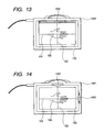
- FIG. 17 shows a tenth embodiment where an indicator 1702 is arranged in the vicinity of a corner of a frame line 103 of an enclosure plane of an X-ray image taking apparatus 1701.
- reference numeral 1703 denotes an object and a case where the right arm of a person is positioned along a diagonal line of the frame line 103 is illustrated as an example.
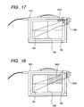
- FIG. 18 shows an eleventh embodiment where the color tint in a region 1802 divided by center lines 104 and 105 of an enclosure plane of an X-ray image taking apparatus 1801 is set so as to be different from those in other regions. That is, in this embodiment, the region 1802 is displayed so as to be distinguished from the other regions.
- FIG. 19 shows a twelfth embodiment where the color tint in a region 1902 in the vicinity of the intersection of center lines 104 and 105 of an enclosure plane of an X-ray image taking apparatus 1901 is set so as to be different from those in other regions, thereby setting the region 1902 as an indicator.
- FIG. 20 shows a thirteenth embodiment where a center line extending between the long sides of an enclosure plane of an X-ray image taking apparatus 2001 and a center line extending between the short sides of the enclosure plane are divided at their centers and solid line portions 2002 and 2004 and dotted line portions 2003 and 2005 are displayed so as to be distinguished from each other.
- FIG. 21 shows a fourteenth embodiment where instead of the frame line 103, indicators 2102, 2103, 2104, and 2105 indicating a range in a short-side direction of a rectangular detection area and indicators 2106, 2107, 2108, and 2109 indicating a range in a long-side direction thereof are arranged for an enclosure plane of an X-ray image taking apparatus 2101. Also, indicators 2110 and 2111 indicating the center in the short-side direction and indicators 2112 and 2113 indicating the center in the long-side direction are provided. Further, the opposing indicators 2110 and 2111 are set so as to have different color tints and the opposing indicators 2112 and 2113 are set so as to have different color tints. In this manner, the indicators 2110 to 2113 are set as indicators of rotation within a detection plane.
- the enclosure of the X-ray image-taking apparatus is provided with a communication cable and a grip
- the enclosure may have a shape that is rotation-symmetric within the detection plane.
- the detection plane of the X-ray detection means is not limited to the rectangular shape.
- each indicator for discrimination of a rotation direction is arranged in the vicinity of its corresponding center line of a detection plane, it also becomes easy to arrange an object in the center portion of the detection plane.
- each indicator for discrimination of a rotation direction has a length that is approximately equal to the length of its corresponding side of the outer frame of a detection plane, there rarely occurs a situation where the indicator is hidden behind an object, which facilitates confirmation.
- each indicator for discrimination of a rotation direction exists in the vicinity of two sides of an outer frame or in the vicinity of one corner thereof, in particular when positioning is performed along a diagonal line of the rectangular shape of a detection plane, it becomes easy to recognize a specific corner of the detection plane.
- an object of the present invention may also be accomplished by supplying a system or an apparatus with a storage medium storing a program code of software that realizes the functions of the above-mentioned embodiments and causing a computer (or a CPU or an MPU) of the system or the apparatus to read out and execute the program code stored in the storage medium.
- the program code itself read out from the storage medium realizes the functions of the above-mentioned embodiments, which means that the storage medium storing the program code also constitutes the present invention.
- Examples of the storage medium for supplying the program code include a flexible disk, a hard disk, an optical disk, a magneto-optical disk, a CD-ROM, a CD-R, a magnetic tape, a nonvolatile memory card, a ROM, and the like.
- the functions of the above-mentioned embodiments may be accomplished not only by executing the program code read out by the computer but also by causing an operating system (OS) or the like running on the computer to perform a part or all of actual processing based on instructions of the program code.
- OS operating system
- the functions of the above-mentioned embodiments may be accomplished by writing the program code read out from the storage medium into a memory provided on a function expansion board inserted into the computer or a function expansion unit connected to the computer and then causing a CPU or the like provided on the function expansion board or the function expansion unit to perform a part or all of the actual processing based on instructions of the program code.
- the X-ray image taking apparatus provides an effect that it is possible for an image taking person to recognize the positional relationship between the X-ray image taking apparatus and an object with ease.
- the present invention relates to a radiation image taking apparatus including: a radiation image acquisition portion that acquires an electronic image based on a radiation transmitted through an object and outputs the electronic image; an image taking direction designation portion that designates a posture of the object with respect to the radiation image acquisition portion; a display portion that displays the posture of the object on at least one plane of the radiation image acquisition portion; and a coordinate conversion portion that performs coordinate conversion of the electronic image.
- the radiation image taking apparatus further includes a control portion that controls the displaying of the posture by the display portion and the coordinate conversion by the coordinate conversion portion based on the posture designated by the image taking direction designation portion.
Landscapes
- Health & Medical Sciences (AREA)
- Life Sciences & Earth Sciences (AREA)
- Engineering & Computer Science (AREA)
- Medical Informatics (AREA)
- Physics & Mathematics (AREA)
- High Energy & Nuclear Physics (AREA)
- Molecular Biology (AREA)
- Nuclear Medicine, Radiotherapy & Molecular Imaging (AREA)
- Biomedical Technology (AREA)
- Veterinary Medicine (AREA)
- Public Health (AREA)
- Optics & Photonics (AREA)
- Pathology (AREA)
- Radiology & Medical Imaging (AREA)
- Biophysics (AREA)
- Heart & Thoracic Surgery (AREA)
- Surgery (AREA)
- Animal Behavior & Ethology (AREA)
- General Health & Medical Sciences (AREA)
- General Physics & Mathematics (AREA)
- Spectroscopy & Molecular Physics (AREA)
- Human Computer Interaction (AREA)
- Apparatus For Radiation Diagnosis (AREA)
Claims (11)
- Strahlungsbildaufnahmevorrichtung mit:einem Strahlungsbilderhalteabschnitt (101) zur Umwandlung eines durch ein Objekt (108) transmittierten Strahlungsbildes in ein elektronisches Bild und zur Ausgabe des elektronischen Bildes, wobei der Strahlungsbilderhalteabschnitt mindestens eine Ebene aufweist;einem Bildaufnahmerichtung-Bestimmungsabschnitt (306) zur Bestimmung einer Bildaufnahmerichtung des Objekts;einem Anzeigeabschnitt (106, 701, 1102, 1202) zur Anzeige der Bildaufnahmerichtung des Objekts auf der mindestens einen Ebene des Strahlungsbilderhalteabschnitts;einem Koordinatenumwandlungsabschnitt (304) zur Durchführung einer Koordinatenumwandlung des elektronischen Bildes; undeinem Steuerabschnitt (302) zur Steuerung der Anzeige der Bildaufnahmerichtung durch den Anzeigeabschnitt und der Koordinatenumwandlung durch den Koordinatenumwandlungsabschnitt beruhend auf der durch den Bildaufnahmerichtung-Bestimmungsabschnitt (306) bestimmten Bildaufnahmerichtung.
- Strahlungsbildaufnahmevorrichtung gemäß Anspruch 1, mit:einem zweiten Bildanzeigeabschnitt (201) zur Anzeige eines elektronischen Nach-Koordinaten-Umwandlungs-Bildes.
- Strahlungsbildaufnahmevorrichtung gemäß Anspruch 1,
wobei der Anzeigeabschnitt gebildet ist aus
einem Indikator (106), der elektrisch ein-/ausgeschaltet werden kann, oder aus
einem Indikator (701), der mittels einer mechanischen Einrichtung selektiv gezeigt/verborgen werden kann. - Strahlungsbildaufnahmevorrichtung gemäß Anspruch 1,
wobei der Anzeigeabschnitt aus einem zweidimensionalen Bildschirm (1202) gebildet ist und zur Anzeige eines zweidimensionalen Bildes eingerichtet ist. - Strahlungsbildaufnahmevorrichtung gemäß Anspruch 1,
wobei der Anzeigeabschnitt außerhalb eines Erfassungsbereiches des Strahlungsbilderhalteabschnitts angeordnet ist. - Strahlungsbildaufnahmevorrichtung gemäß Anspruch 3,
wobei der Indikator in der Nähe einer Mittellinie in Längsrichtung eines Erfassungsbereiches des Strahlungsbilderhalteabschnitts angeordnet ist, der in rechtwinkliger Form gebildet ist, oder einer Mittellinie in Richtung der kurzen Seite des Erfassungsbereichs angeordnet ist. - Strahlungsbildaufnahmevorrichtung gemäß Anspruch 6,
wobei der Strahlungsbilderhalteabschnitt eine Erfassungsebene aufweist, auf der mehrere photoelektrische Wandlerelemente in einer zweidimensionalen Weise angeordnet sind, wobei eine Kombination aus Lichtemission, Nicht-Lichtemission und Lichtemissionsfarbe des Indikators als Muster bezeichnet wird, und wobei, wenn eine Schwerpunktsposition der Erfassungsebene als Drehpunkt eingestellt ist, der Anzeigeabschnitt zur Durchführung der Anzeige derart eingerichtet ist, dass das Muster nicht rotationssymmetrisch ist. - Strahlungsbildaufnahmevorrichtung gemäß Anspruch 1, mit:einem Speicherabschnitt (303) zum Speichern von eine Benennung des Objekts und die Bildaufnahmerichtung betreffenden Informationen, so dass sie miteinander verbunden sind,wobei, wenn die die Benennung des Objekts (108) betreffenden Informationen durch den Bildaufnahmerichtung-Bestimmungsabschnitt (306) eingegeben werden, der Steuerabschnitt zur Steuerung der Anzeige der Bildaufnahmerichtung durch den Anzeigeabschnitt und der Koordinaten-Umwandlung durch den Koordinaten-Umwandlungsabschnitt (304) basierend auf der mit den eingegebenen Informationen verbundenen Bildaufnahmerichtung eingerichtet ist.
- Strahlungsbildaufnahmeverfahren, mit dem eine Bildaufnahmerichtung eines Objekts (108) auf mindestens einer Ebene eines Strahlungsbilderhalteabschnitts (101) angezeigt wird, mit:einem Bildaufnahmerichtung-Bestimmungsschritt (S401, S402) zur Bestimmung der Bildaufnahmerichtung des Objekts;einem Strahlungsbilderhalteschritt (S404) zur Umwandlung eines durch das Objekt (108) transmittierten Strahlungsbildes in ein elektronisches Bild und zur Ausgabe des elektronischen Bildes;einem Koordinaten-Umwandlungsschritt (S405) zur Durchführung einer Koordinaten-Umwandlung des elektronischen Bildes;einem Anzeigeschritt (S406) zur Anzeige der Bildaufnahmerichtung des Objekts auf der mindestens einen Ebene des Strahlungsbilderhalteabschnitts; undeinem Steuerschritt zur Steuerung der Anzeige der Bildaufnahmerichtung im Anzeigeschritt und der Koordinaten-Umwandlung in dem Koordinaten-Umwandlungsschritt basierend auf der in dem Bildaufnahmerichtung-Bestimmungsschritt bestimmten Bildaufnahmerichtung.
- Steuerprogramm zur Veranlassung der Strahlungsbildaufnahmevorrichtung gemäß einem der Ansprüche 1 bis 8 zur Ausführung des Strahlungsbildaufnahmeverfahrens gemäß Anspruch 9.
- Strahlungsbildaufnahmesystem mit:einer Strahlung ausstrahlenden Strahlungserzeugungsvorrichtung (308); undeiner Vielzahl von in einer gegenseitig kommunizierenden Weise miteinander verbundenen Vorrichtungen,wobei mindestens eine aus der Vielzahl der Vorrichtungen eine Strahlungsbildaufnahmevorrichtung gemäß einem der Ansprüche 1 bis 8 ist.
Applications Claiming Priority (2)
| Application Number | Priority Date | Filing Date | Title |
|---|---|---|---|
| JP2003209517A JP3862681B2 (ja) | 2003-08-29 | 2003-08-29 | X線画像撮影装置 |
| JP2003209517 | 2003-08-29 |
Publications (3)
| Publication Number | Publication Date |
|---|---|
| EP1519557A2 EP1519557A2 (de) | 2005-03-30 |
| EP1519557A3 EP1519557A3 (de) | 2005-10-19 |
| EP1519557B1 true EP1519557B1 (de) | 2013-06-26 |
Family
ID=34190103
Family Applications (1)
| Application Number | Title | Priority Date | Filing Date |
|---|---|---|---|
| EP04020315.0A Expired - Lifetime EP1519557B1 (de) | 2003-08-29 | 2004-08-26 | Strahlungsbildaufnahmevorrichtung, Strahlungsbildaufnahmesystem, Strahlungsbildaufnahmeverfahren |
Country Status (5)
| Country | Link |
|---|---|
| US (1) | US7092491B2 (de) |
| EP (1) | EP1519557B1 (de) |
| JP (1) | JP3862681B2 (de) |
| KR (1) | KR100739583B1 (de) |
| CN (1) | CN1591176B (de) |
Families Citing this family (28)
| Publication number | Priority date | Publication date | Assignee | Title |
|---|---|---|---|---|
| DE102005018004A1 (de) * | 2005-04-18 | 2006-10-19 | Siemens Ag | Mobiler Röntgen-Flachdetektor mit Tragegriff |
| US8041093B2 (en) * | 2005-04-22 | 2011-10-18 | General Electric Company | System and method for definition of DICOM header values |
| JP4384091B2 (ja) | 2005-07-13 | 2009-12-16 | キヤノン株式会社 | 可搬型放射線撮影装置 |
| US20080019480A1 (en) * | 2006-07-24 | 2008-01-24 | Kuei-Wen Cheng | Method and apparatus for controlling x-ray machine to irradiate a narrowed portion |
| US20080025475A1 (en) * | 2006-07-25 | 2008-01-31 | Synarc, Inc. | Apparatus for determining the position and orientation in medical imaging |
| US20080037711A1 (en) * | 2006-07-25 | 2008-02-14 | Synarc, Inc. | Apparatus for positioning and labeling an appendage in x-radiography |
| US20080025466A1 (en) * | 2006-07-25 | 2008-01-31 | Synarc, Inc. | Apparatus for determining the position and orientation of an x-ray source |
| USD589525S1 (en) * | 2006-08-03 | 2009-03-31 | Catalis, Inc. | Computer display with transitional anatomical structure image |
| JP4829163B2 (ja) * | 2007-03-30 | 2011-12-07 | 富士フイルム株式会社 | 放射線画像撮影装置及び放射線画像撮影方法 |
| US7783008B2 (en) * | 2007-03-30 | 2010-08-24 | General Electric Company | Digital radiograph patient positioning system and method |
| JP2010184025A (ja) * | 2009-02-12 | 2010-08-26 | Fujifilm Corp | 放射線画像撮影システム、電源装置、充電装置、および放射線画像撮影方法 |
| WO2012156861A1 (en) | 2011-05-13 | 2012-11-22 | Koninklijke Philips Electronics N.V. | Orientation reference system for medical imaging |
| JP6139205B2 (ja) * | 2013-03-26 | 2017-05-31 | 株式会社日立製作所 | X線測定装置 |
| KR20140137715A (ko) * | 2013-05-23 | 2014-12-03 | 삼성디스플레이 주식회사 | 엑스레이 검출 장치 및 방법 |
| JP6170863B2 (ja) * | 2014-03-28 | 2017-07-26 | 富士フイルム株式会社 | 電子カセッテ |
| USD724099S1 (en) * | 2014-08-29 | 2015-03-10 | Nike, Inc. | Display screen with emoticon |
| USD723579S1 (en) * | 2014-08-29 | 2015-03-03 | Nike, Inc. | Display screen with emoticon |
| USD724098S1 (en) | 2014-08-29 | 2015-03-10 | Nike, Inc. | Display screen with emoticon |
| USD725131S1 (en) * | 2014-08-29 | 2015-03-24 | Nike, Inc. | Display screen with emoticon |
| USD726199S1 (en) | 2014-08-29 | 2015-04-07 | Nike, Inc. | Display screen with emoticon |
| USD723578S1 (en) * | 2014-08-29 | 2015-03-03 | Nike, Inc. | Display screen with emoticon |
| USD724606S1 (en) * | 2014-08-29 | 2015-03-17 | Nike, Inc. | Display screen with emoticon |
| USD725130S1 (en) * | 2014-08-29 | 2015-03-24 | Nike, Inc. | Display screen with emoticon |
| USD723046S1 (en) * | 2014-08-29 | 2015-02-24 | Nike, Inc. | Display screen with emoticon |
| USD725129S1 (en) * | 2014-08-29 | 2015-03-24 | Nike, Inc. | Display screen with emoticon |
| USD723577S1 (en) * | 2014-08-29 | 2015-03-03 | Nike, Inc. | Display screen with emoticon |
| CN113574367B (zh) * | 2019-06-07 | 2025-05-30 | 株式会社前川制作所 | 图像处理装置、图像处理程序及图像处理方法 |
| JP7533692B2 (ja) * | 2022-06-08 | 2024-08-14 | コニカミノルタ株式会社 | X線検出装置およびx線撮影装置 |
Citations (1)
| Publication number | Priority date | Publication date | Assignee | Title |
|---|---|---|---|---|
| US20020080921A1 (en) * | 1999-10-06 | 2002-06-27 | Smith Andrew P. | Digital flat panel x-ray receptor positioning in diagnostic radiology |
Family Cites Families (10)
| Publication number | Priority date | Publication date | Assignee | Title |
|---|---|---|---|---|
| US4242587A (en) * | 1979-06-07 | 1980-12-30 | Charles Lescrenier | Patient positioning device comprising light planes corresponding to first, second and third intersecting reference planes |
| JP3456718B2 (ja) * | 1993-01-27 | 2003-10-14 | 株式会社東芝 | X線撮影装置 |
| JP3619027B2 (ja) * | 1998-09-30 | 2005-02-09 | キヤノン株式会社 | X線撮影装置、x線撮影システム、x線画像処理方法、及びコンピュータ読み取り可能な記録媒体 |
| AU6673600A (en) * | 1999-08-09 | 2001-03-05 | University Of British Columbia, The | Method and automated system for creating volumetric data sets |
| US6354737B1 (en) * | 1999-11-12 | 2002-03-12 | Direct Radiography Corp. | Digital image orientation marker |
| US6510197B1 (en) * | 2000-01-11 | 2003-01-21 | Alara, Inc. | Method and apparatus for osteoporosis screening |
| JP4617017B2 (ja) | 2001-03-29 | 2011-01-19 | キヤノン株式会社 | X線撮影装置 |
| DE10151236B4 (de) * | 2001-10-17 | 2008-11-13 | Siemens Ag | Vorrichtung zur optimierten Patienten-Positionierung bei Strahlenuntersuchungen und/oder Strahlenbehandlungen |
| US6590958B2 (en) * | 2001-11-15 | 2003-07-08 | Ge Medical Systems Global Technology | X-ray positioner having integrated display |
| JP3950716B2 (ja) * | 2002-03-06 | 2007-08-01 | ジーイー・メディカル・システムズ・グローバル・テクノロジー・カンパニー・エルエルシー | X線ct装置、及びその制御方法 |
-
2003
- 2003-08-29 JP JP2003209517A patent/JP3862681B2/ja not_active Expired - Fee Related
-
2004
- 2004-08-25 KR KR1020040066996A patent/KR100739583B1/ko not_active Expired - Fee Related
- 2004-08-26 CN CN200410057357XA patent/CN1591176B/zh not_active Expired - Fee Related
- 2004-08-26 EP EP04020315.0A patent/EP1519557B1/de not_active Expired - Lifetime
- 2004-08-27 US US10/927,976 patent/US7092491B2/en not_active Expired - Fee Related
Patent Citations (1)
| Publication number | Priority date | Publication date | Assignee | Title |
|---|---|---|---|---|
| US20020080921A1 (en) * | 1999-10-06 | 2002-06-27 | Smith Andrew P. | Digital flat panel x-ray receptor positioning in diagnostic radiology |
Also Published As
| Publication number | Publication date |
|---|---|
| KR100739583B1 (ko) | 2007-07-16 |
| KR20050021257A (ko) | 2005-03-07 |
| US20050047549A1 (en) | 2005-03-03 |
| JP3862681B2 (ja) | 2006-12-27 |
| CN1591176B (zh) | 2010-09-01 |
| EP1519557A3 (de) | 2005-10-19 |
| US7092491B2 (en) | 2006-08-15 |
| EP1519557A2 (de) | 2005-03-30 |
| JP2005073706A (ja) | 2005-03-24 |
| CN1591176A (zh) | 2005-03-09 |
Similar Documents
| Publication | Publication Date | Title |
|---|---|---|
| EP1519557B1 (de) | Strahlungsbildaufnahmevorrichtung, Strahlungsbildaufnahmesystem, Strahlungsbildaufnahmeverfahren | |
| EP3453330B1 (de) | Virtuelles positionierungsbild zur verwendung bei der bilderzeugung | |
| US11832021B2 (en) | Control apparatus, control method, and storage medium | |
| EP0609500A1 (de) | Eine im manuellen oder automatischen Modus betätigbare Workstation zur Qualitätskontrolle von digitalen radiographischen Bildern | |
| US20160015340A1 (en) | Radiography system, console and electronic cassette | |
| US6944269B2 (en) | Medical imaging examination facility | |
| US20100104065A1 (en) | Radiographic image photographing system and control device | |
| JP3651930B2 (ja) | 放射線検査ワークステーションにおけるリアルタイムなウィンドウ/レベル化システム | |
| EP0599097B1 (de) | Automatische Leitwegsuche von digitalen Röntgenbildern zum gewählten Ziel | |
| JP6256042B2 (ja) | 放射線画像撮影システム | |
| US20230301609A1 (en) | Imaging systems and methods | |
| WO2023015110A1 (en) | Improved imaging systems and methods | |
| US20050100136A1 (en) | Image displaying apparatus and program | |
| US20210121138A1 (en) | Computed tomography and positioning of the anatomy desired to be imaged | |
| CN100594842C (zh) | 放射线图像连接处理方法、放射线图像连接处理装置 | |
| CN119654105A (zh) | 用于执行脑部扫描的ct扫描器和扫描方法 | |
| WO2023183854A1 (en) | Improved imaging systems and methods | |
| JPH08251576A (ja) | 画像表示方法および装置 | |
| JP2006122304A (ja) | 放射線画像撮影システム | |
| KR20170000337A (ko) | 엑스선 장치 및 그 제어 방법 | |
| JP2006296954A (ja) | 画像取得装置 | |
| JP2025169731A (ja) | 放射線撮影システム | |
| JP2025169730A (ja) | 放射線撮影システム | |
| JP2016158811A (ja) | 制御装置、制御方法、医用画像撮影装置、医用画像撮影システムおよびプログラム | |
| CN119924866A (zh) | 一种放射性射线成像的方法及设备 |
Legal Events
| Date | Code | Title | Description |
|---|---|---|---|
| PUAI | Public reference made under article 153(3) epc to a published international application that has entered the european phase |
Free format text: ORIGINAL CODE: 0009012 |
|
| AK | Designated contracting states |
Kind code of ref document: A2 Designated state(s): AT BE BG CH CY CZ DE DK EE ES FI FR GB GR HU IE IT LI LU MC NL PL PT RO SE SI SK TR |
|
| AX | Request for extension of the european patent |
Extension state: AL HR LT LV MK |
|
| PUAL | Search report despatched |
Free format text: ORIGINAL CODE: 0009013 |
|
| AK | Designated contracting states |
Kind code of ref document: A3 Designated state(s): AT BE BG CH CY CZ DE DK EE ES FI FR GB GR HU IE IT LI LU MC NL PL PT RO SE SI SK TR |
|
| AX | Request for extension of the european patent |
Extension state: AL HR LT LV MK |
|
| RIC1 | Information provided on ipc code assigned before grant |
Ipc: 7G 01T 1/29 B Ipc: 7A 61B 6/04 B Ipc: 7H 04N 1/00 A |
|
| 17P | Request for examination filed |
Effective date: 20060419 |
|
| AKX | Designation fees paid |
Designated state(s): DE FR GB NL |
|
| 17Q | First examination report despatched |
Effective date: 20060419 |
|
| GRAP | Despatch of communication of intention to grant a patent |
Free format text: ORIGINAL CODE: EPIDOSNIGR1 |
|
| GRAS | Grant fee paid |
Free format text: ORIGINAL CODE: EPIDOSNIGR3 |
|
| GRAA | (expected) grant |
Free format text: ORIGINAL CODE: 0009210 |
|
| RIN1 | Information on inventor provided before grant (corrected) |
Inventor name: OKODA, KEIJI |
|
| AK | Designated contracting states |
Kind code of ref document: B1 Designated state(s): DE FR GB NL |
|
| REG | Reference to a national code |
Ref country code: GB Ref legal event code: FG4D |
|
| REG | Reference to a national code |
Ref country code: DE Ref legal event code: R096 Ref document number: 602004042525 Country of ref document: DE Effective date: 20130822 |
|
| REG | Reference to a national code |
Ref country code: NL Ref legal event code: T3 |
|
| PLBE | No opposition filed within time limit |
Free format text: ORIGINAL CODE: 0009261 |
|
| STAA | Information on the status of an ep patent application or granted ep patent |
Free format text: STATUS: NO OPPOSITION FILED WITHIN TIME LIMIT |
|
| REG | Reference to a national code |
Ref country code: FR Ref legal event code: ST Effective date: 20140430 |
|
| GBPC | Gb: european patent ceased through non-payment of renewal fee |
Effective date: 20130926 |
|
| 26N | No opposition filed |
Effective date: 20140327 |
|
| REG | Reference to a national code |
Ref country code: DE Ref legal event code: R097 Ref document number: 602004042525 Country of ref document: DE Effective date: 20140327 |
|
| PG25 | Lapsed in a contracting state [announced via postgrant information from national office to epo] |
Ref country code: GB Free format text: LAPSE BECAUSE OF NON-PAYMENT OF DUE FEES Effective date: 20130926 |
|
| PG25 | Lapsed in a contracting state [announced via postgrant information from national office to epo] |
Ref country code: FR Free format text: LAPSE BECAUSE OF NON-PAYMENT OF DUE FEES Effective date: 20130902 |
|
| PGFP | Annual fee paid to national office [announced via postgrant information from national office to epo] |
Ref country code: NL Payment date: 20170828 Year of fee payment: 14 |
|
| PGFP | Annual fee paid to national office [announced via postgrant information from national office to epo] |
Ref country code: DE Payment date: 20171030 Year of fee payment: 14 |
|
| REG | Reference to a national code |
Ref country code: DE Ref legal event code: R119 Ref document number: 602004042525 Country of ref document: DE |
|
| REG | Reference to a national code |
Ref country code: NL Ref legal event code: MM Effective date: 20180901 |
|
| PG25 | Lapsed in a contracting state [announced via postgrant information from national office to epo] |
Ref country code: NL Free format text: LAPSE BECAUSE OF NON-PAYMENT OF DUE FEES Effective date: 20180901 |
|
| PG25 | Lapsed in a contracting state [announced via postgrant information from national office to epo] |
Ref country code: DE Free format text: LAPSE BECAUSE OF NON-PAYMENT OF DUE FEES Effective date: 20190301 |