EP1519335B1 - Spielgerät - Google Patents
Spielgerät Download PDFInfo
- Publication number
- EP1519335B1 EP1519335B1 EP04022797A EP04022797A EP1519335B1 EP 1519335 B1 EP1519335 B1 EP 1519335B1 EP 04022797 A EP04022797 A EP 04022797A EP 04022797 A EP04022797 A EP 04022797A EP 1519335 B1 EP1519335 B1 EP 1519335B1
- Authority
- EP
- European Patent Office
- Prior art keywords
- payout
- medals
- lottery
- gaming machine
- medal
- Prior art date
- Legal status (The legal status is an assumption and is not a legal conclusion. Google has not performed a legal analysis and makes no representation as to the accuracy of the status listed.)
- Expired - Lifetime
Links
- 230000000694 effects Effects 0.000 abstract description 6
- 230000004913 activation Effects 0.000 description 22
- 238000001514 detection method Methods 0.000 description 18
- 230000004044 response Effects 0.000 description 14
- 230000007246 mechanism Effects 0.000 description 10
- 239000003086 colorant Substances 0.000 description 6
- 230000006870 function Effects 0.000 description 6
- 230000005284 excitation Effects 0.000 description 5
- 230000008859 change Effects 0.000 description 4
- 239000002184 metal Substances 0.000 description 4
- 230000004308 accommodation Effects 0.000 description 3
- 238000005192 partition Methods 0.000 description 3
- 239000004925 Acrylic resin Substances 0.000 description 2
- 229920000178 Acrylic resin Polymers 0.000 description 2
- 238000010586 diagram Methods 0.000 description 2
- 230000002779 inactivation Effects 0.000 description 2
- 230000003247 decreasing effect Effects 0.000 description 1
- 229910052755 nonmetal Inorganic materials 0.000 description 1
- 230000002093 peripheral effect Effects 0.000 description 1
- 238000005070 sampling Methods 0.000 description 1
Images









Classifications
-
- G—PHYSICS
- G07—CHECKING-DEVICES
- G07F—COIN-FREED OR LIKE APPARATUS
- G07F17/00—Coin-freed apparatus for hiring articles; Coin-freed facilities or services
- G07F17/32—Coin-freed apparatus for hiring articles; Coin-freed facilities or services for games, toys, sports, or amusements
- G07F17/3286—Type of games
- G07F17/3297—Fairground games, e.g. Tivoli, coin pusher machines, cranes
Definitions
- the present invention relates to a gaming machine which is installed in a so-called game arcade or the like.
- US 2003/0114221 A1 discloses a gaming machine which can accept payment in a plurality of forms, and can pay out to a player in a corresponding plurality of forms, such as in currency or by account transfer.
- the present invention provides the following:
- medals imply not only so-called medals but also any kinds of small metal or non-metal discs including coins, tokens and the like.
- Fig. 1 is a perspective view which schematically shows the gaming machine 10 according to one specific embodiment
- Fig. 2 is a perspective view showing a clock tower 13 mounted in the gaming machine 10.
- the gaming machine 10 includes a longitudinal square columnar casing 12 and a top plate 18 thereof is supported by four support struts 17 which are arranged at side portions of the casing 12. Further, transparent windows 14 are respectively formed in side surfaces of the casing 12. A space which is surrounded by the top plate 18 and four windows 14 defines a gaming space 15 for performing a game using medals. A player can observe the inside of the gaming space 15 through the window 14 with naked eyes.
- Two launching devices 16 are provided to a lower portion of each window 14. That is, although not shown in the drawing, the gaming machine 10 is, as a whole, provided with eight launching devices 16.
- These launching devices 16 are provided for allowing the launching of the medals into the inside of the gaming space 15, wherein the launching devices 16 are mounted such that the launching devices 16 are rotatable within a predetermined range in the vertical direction as well as in the left-and-right direction.
- the launching device 16 When a player determines the direction that the player launches medals by rotating the launching device 16 manually and at the same time, pulls a launching trigger 40 (not shown in the drawing) provided to the launching device 16, the medals are launched to the inside of the gaming space 15.
- a launching trigger 40 (not shown in the drawing) provided to the launching device 16
- the medals are launched to the inside of the gaming space 15.
- the launching device 16 is explained in detail later.
- Medal receptacle mounting places 32 formed on lower portions of the launching devices 16 are provided for mounting receptacles in which the medals are launched. Further, in the inside of the medal pan 31 which is arranged below the medal receptacle mounting places 32, the medals which are paid out from the gaming machine 10 and are given to the player are stored.
- the longitudinally elongated clock tower 13 having the approximately quadrangular columnar shape is mounted in an erected manner.
- push-out plates 35 on which the medals are mounted are provided below the clock tower 13. That is, although not shown in the drawing, four push-out plates 35 in total are respectively provided at positions which correspond to the respective windows 14 of the casing 12.
- a so-called pusher game is performed on the push-out plate 35. That is, the push-out plate 35 is formed in a stepped shape by stacking a plurality of plate-like bodies and a predetermined plate-like body is configured to be slidable in the fore-and-aft direction. Further, a medal discharge port 34 is formed in front of the push-out plate 35 and, along with the slide movement of the plate-like body in the fore-and-aft direction, the medals on the push-out plate 35 fall in the medal discharge port 34. Among the fallen medals, the medals which pass a predetermined region are paid out to the metal reception pan 31 and given to the player.
- the medals which do not pass the predetermined region are transported to the top plate 18 by means of a transport elevator (not shown in the drawing) disposed inside the support strut 17, pass through the inside of the chute (not shown in the drawing) which is disposed inside the top plate 18, and fall into the medal accumulating device portion 30 which is mounted on an uppermost portion of the clock tower 13.
- An opening 37 is formed above the push-out plate 35 and a chucker 36 which imitates a pendulum of a clock is arranged in the inside of the opening 37.
- the chucker 36 is always tilting in the left-and-right direction within a predetermined range and a player launches a medal into the inside of the gaming space 15 using the launching device 16 while using the chucker 36 as a target.
- the chucker 36 incorporates a medal detection sensor 38 (not shown in the drawings).
- a contact of the medal with the chucker 36 is detected by the medal detection sensor 38, a lottery which determines the presence or the non-presence of the activation of jackpot as the satisfaction of predetermined conditions (the lottery also being referred to as JP lottery) is performed and, based on a result of the lottery, a jackpot game described later is performed. Further, the medal which has passed the opening 37 falls on the push-out plate 35 irrespective of the presence or the non-presence of the hitting or the impingement of the medal on the chucker 36.
- a medal accumulating device portion 30 is formed on an uppermost portion of the clock tower 13.
- this medal accumulating device portion 30 as described above, the medals which are transported by transport elevators disposed inside the support struts 17 and pass through chutes arranged in the inside of the top plate 18 are accumulated. Further, the medals which are accumulated in the medal accumulating device portion 30 are paid out toward the push-out plate 35 by the payout devices 80 to 83 (not shown in the drawing) when a jackpot is activated in a jackpot game.
- the lottery alarm display devices 20 which imitate a clock are formed at positions corresponding to two launching devices 16 provided to respective windows 14.
- the lottery alarm display devices 20 includes a short hand 21, a long hand 22 and a face 23, wherein the jackpot game is performed using this lottery alarm display devices 20.
- the jackpot game is served for informing a result of the JP lottery. That is, in this game, when the short hand 21 and the long hand 22 are rotated and thereafter they are stopped and the positions of the stopped short hand 21 and long hand 22 assume predetermined positions, the jackpot is activated and the pay-out of the medal to the push-out plate 35 is started.
- These lottery alarm display devices 20 can be opened or closed using upper sides thereof as pivot shafts and function as medal payout gates. Further, at portions which are surrounded by four lottery alarm display devices 20 (the medal payout gates), payout devices 80 to 83 which correspond to the respective lottery alarm display devices 20 are provided. When the jackpot is activated in any one of the lottery alarm display devices 20, the lottery alarm display device 20 (the medal payout gate) is opened. Further, using the payout devices 80 to 83 corresponding to the lottery alarm display device 20 (the medal payout gate), the medal accumulated in the medal accumulating device portion 30 are paid out toward the push-out plates 35.
- the lottery alarm display devices 20 and the payout devices 80 to 83 are explained in detail later in conjunction with drawings.
- each lottery alarm display device 20 eight holding lamps 33 are respectively arranged.
- the holding lamps 33 show the holding number of the jackpot games based on the number of holding lamps 33 which are turned on. Each time the medal 36 hits the chucker 36 during the execution of the jackpot game, the lit number of the holding lamps is increased by one and the jackpot game is held, while the jackpot game under execution is stopped, one holding lamp is turned off and the held jackpot games are performed.
- the gaming machine 10 can be played by eight players simultaneously at maximum.
- two launching devices 16 are provided in each window 14 of the housing 12.
- respective devices necessary for the game such as the push-out plate 35, the lottery alarm display device 20 (the medal payout gate), the chucker 36, and the holding lamp 33 are formed as one set corresponding to two launching devices 16 thus constituting one gaming field. That is, in the gaming machine 10, four gaming fields are provided and the games are performed independently in respective gaming fields.
- the medal accumulating device portion 30 is formed on the uppermost portion of the clock tower 13 in common with all gaming fields. When the jackpot is activated in the jackpot game, the medals accumulated in the medal accumulating device portion 30 are paid out toward the push-out plate 35 formed below the lottery alarm display device 20 on which the jackpot is activated.
- Fig. 3 is a cross-sectional view showing the launching device 16 mounted in the gaming machine 10.
- the launching device 16 has a shape which imitates a gun.
- the launching device 16 has a portion thereof launched to an opening portion 14a formed in the window 14.
- the launching device 16 is mounted in the opening portion 14a with a rotary mechanism 42 and is configured to be capable of changing a direction thereof in the vertical direction as well as in the left-and-right direction.
- a launching trigger 40 On a player side (a left side in the drawing) of the launching device 16, a launching trigger 40, a grip 41, a medal loading port 44 and a push bar 46 are provided.
- the push bar 46 moves in the frontward direction (a right direction in the drawing) so as to feed one medal disposed at a lowermost stage out of the medals loaded in the medal loading port 44 forwardly.
- the launching trigger 40 is released, the push bar 46 returns to the original position and the medal which is loaded in the medal loading port 44 falls therein and hence, it is possible to feed the medal forwardly again using the push bar 46.
- the medal which is pushed frontwardly by the push bar 46 is moved to a position below a roller 43 which is connected with a launching motor 47 (not shown in the drawing).
- the roller 43 is configured to be rotatable along with the rotation of the launching motor 47 for a predetermined period after pulling the launching trigger 40.
- the medal which is fed to a lower portion of the roller 43 is launched to the inside of the gaming space 15 from a medal launching port 45 due to the rotation of the roller 43.
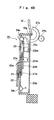
- Fig. 4A is a back view for schematically showing the lottery alarm display device 20 (the medal payout gate) arranged in the clock tower 13, and Fig. 4B is a cross-sectional view of the lottery alarm display device 20.
- a cylindrical shaft portion 21a is rotatably mounted, while a transparent short hand 21 made of acrylic resin is fixed to one end of the shaft portion 21a.
- a gear 21b is fixed to another end of the shaft portion 21a and a gear 21c is meshed with the gear 21b.
- a stepping motor 21m is directly connected with the gear 21c. Accordingly, upon the rotation of stepping motor 21m is transmitted through the gear train 21c to 21b in this order and the short hand 21 is rotated.
- a shaft portion 22a is rotatably mounted such that the shaft portion 22a penetrates the shaft portion 21a of the short hand 21, while a transparent long hand 22 made of acrylic resin is fixed to one end of the shaft portion 22a.
- a gear 22b is fixed to another end of the shaft portion 22a, while a gear 22c is meshed with the gear 22b.
- a gear 22d is meshed with the gear 22c, while stepping motor 22m is directly connected with the gear 22d. Accordingly, the rotation of stepping motor 22m is transmitted in order of gear trains 22d, 22c, 22b and, thereafter, the long hand 22 is rotated.
- stepping motors 21m, 22m are rotated in response to drive pulses from the motor drive printed circuit board 26 and are changeable between the normal rotation and the reverse rotation.
- decorative lamps 24a to 24d formed of LED are provided. These decorative lamps 24a to 24d are capable of emitting light in plural light emitting colors, wherein the lamps 24a to 24d are arranged to be able to irradiate light to the short hand 21 and/or the long hand 22.
- the decorative lamps 24a to 24d are connected with a LED control printed circuit board 25 and change the light emitting colors or light lit patterns in response to signals from the LED control printed circuit board 25.
- the lottery alarm display device 20 is mounted on the casing 12 by way of the pivot shaft portion 20a formed on an upper side portion thereof such that the lottery alarm display device 20 can be opened and closed.
- an arcuate open/close gear 27a is vertically mounted on a back plate 20b of the lottery alarm display device 20 and a gear 27b is meshed with the open/close gear 27a.
- an open/close motor 27m is directly connected with the gear 27b. The rotation of the open/close motor 27m is transmitted in order of gear trains 27b to 27a so that the lottery alarm display device 20 is released or opened.
- the lottery alarm display device 20 (the medal payout gate) is released along with the rotation of the open/close motor 27m and, at the same time, the medals accumulated in the medal accumulating device portion 30 are discharged toward the push-out plate 35 by the payout devices 80 to 83 (not shown in the drawing) stored in the lottery alarm display device 20.
- the short hand and the long hand have the light guiding property. This is because that the short hand and the long hand can enhance the decorative property thereof when they receive the irradiation of light from the light emitting source (for example, decorative lamps 24 or the like) whereby it is possible to perform effects which can enhance the interests or the excitement of a player.
- the light emitting source for example, decorative lamps 24 or the like
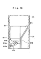
- Fig. 5A is a plan view which schematically shows the medal accumulating device portion 30 formed above the clock tower 13 and Fig. 5B is a longitudinal cross-sectional view schematically showing the medal accumulating device portion 30.
- a wall portion 130 having a rectangular shape in a plan view is formed on the uppermost portion of the clock tower 13 (not shown in the drawing). Inside the wall portion 130, a hopper portion 131 having a bottomless bowl shape is arranged and a rotary disc 132 is provided to a portion which constitutes a bottom of the hopper portion 131.
- the medal accumulating device portion 30 is constituted of the wall portion 130, the hopper portion 131 and the rotary disc 132.
- the rotary disc 132 is configured to be rotated along with the driving of the pay-out motor 139 arranged below the rotary disc 132 and six medal accommodation holes 133 are formed in an outer peripheral portion thereof. In these medal accommodation holes 133, the medals which are accumulated in the medal accumulating device portion 30 are loaded.
- an annular medal guide disc 134 having a circular annular shape is provided such that the medal guide disc 134 shares the center axis in common with the rotary disc 132.
- the medal guide disc 134 is configured to be rotatable along with the driving of the guide motor 135 provided at the lower portion thereof.
- a guide passage 134a is formed such that the guide passage 134a is lower than the upper surface by one step.
- Four medal falling holes 136a to 136d are formed in a lower portion of the medal guide disc 134.
- the medals which are accumulated in the medal accumulating device portion 30 are loaded.
- the loaded medals fall in the guide passages 134a formed in the medal guide disc 134 and pass through the medal falling holes 136 (136a to 136d).
- the payout devices 80 to 83 (not shown in the drawings) which will be described later are provided below the medal falling holes 136a to 136d and hence, the medals which pass through the medal falling holes 136 (136a to 136d) are supplied to the payout devices 80 to 83. Accordingly, along with the rotation of the medal guide disc 134, the positions of the guide passages 134a are changed whereby it is possible to change the payout devices 80 to 83 which become subjects to which the medals are supplied.
- the payout devices 80 to 83 of the gaming machine 10 are explained in conjunction with Fig. 6 to Fig. 9.
- the payout devices 80 to 83 are mounted in a region surrounded by four lottery alarm display devices 20 (medal payout gates) . That is, the region surrounded by four lottery alarm display devices 20 is uniformly divided into four regions by partition walls 120 which are vertically formed along diagonal lines of the region, and the payout devices 80 to 83 are respectively mounted in the partitioned four regions.
- Fig. 6A is a plan view schematically showing the payout device 80 and Fig. 6B is a longitudinal cross-sectional view schematically showing a payout device 80.
- the lottery alarm display device 20 medal payout gate
- the lottery alarm display device 20 is shown in a simplified form in Fig. 6 to Fig. 9.
- the payout device 80 includes a reciprocating tray 800.
- the reciprocating tray 800 having toothed portions 800a formed on the side surfaces thereof can be moved in a reciprocating manner in the fore-and-aft direction (the left-and-right direction in the drawing) by driving a motor 800m provided with a gear 800b which is meshed with the toothed portion 800a.
- a rotary tray 801 having a toothed portion 801a formed on the side surface thereof is mounted above the reciprocating tray 800.
- the toothed portion 801a is meshed with a gear 802a of a motor 802m and, by driving the motor 802m, the rotary tray 801 is rotated.
- the medals which pass through the medal falling holes 136 fall on the rotary tray 801 (see Fig. 5).
- numeral 805 indicates chutes which guide the medals onto the rotary tray 801.
- the payout device 80 With respect to the operation of the payout device 80, first of all, when the lottery alarm display device 20 (medal payout gate) is opened (see Fig. 4), along with the driving of the motor 800m, the reciprocating tray 800 is moved in the forward direction (the left direction in the drawing). Thereafter, along with the driving of the motor 802m, the rotary tray 801 is rotated and the medals stacked on the rotary tray 801 are paid out to the push-out plate 35 (see Fig. 2).
- Fig. 7A is a front view schematically showing a payout device 81 and Fig. 7B is a longitudinal cross-sectional view schematically showing the payout device 81.
- the payout device 81 includes a revolving tray 810. On the front side (the left side in the drawing) of this revolving tray 810, a pivot shaft portion 811 is formed, and the revolving tray 810 is rotatable about this pivot shaft portion 811 within a predetermined range.
- an inner tooth gear 812 which has an arcuate shape and has a toothed portion 812a formed on an inner surface thereof is vertically mounted. Further, a gear 813 of a motor 813m is configured to be meshed with the toothed portion 812a.
- the revolving tray 810 is rotated about the pivot shaft portion 811 within the predetermined range. The medals which pass through the medal falling hole 136 falls on the revolving tray 810 (see Fig. 5).
- numeral 815 indicates a chute which guides the medals onto the revolving tray 810.
- the payout device 81 With respect to the operation of the payout device 81, first of all, when the lottery alarm display device 20 (the medal payout gate) is opened (see Fig. 4), along with the driving of the motor 813m, the revolving tray 810 is rotated about the pivot shaft portion 811 within the predetermined range and the medals stacked on the revolving tray 810 are paid out to the push-out plate 35 (see Fig. 2).
- Fig. 8A is a front view schematically showing a payout device 82 and Fig. 8B is a longitudinal cross-sectional view schematically showing the payout device 82.
- the payout device 82 includes a model body 820 having a dove shape.
- a medal accommodating portion 820a is formed in a drum portion of the model body 820.
- the model body 820 is configured such that the medals which pass through the medal falling hole 136 (see Fig. 5) falls on the medal accommodating portion 820a.
- a bottom surface of the medal accommodating portion 820a is formed in mesh and hence, by imparting predetermined vibrations to the model body 820, the medals stocked in the medal accommodating portion 820a fall downwardly through openings formed in mesh.
- the model body 820 is provided with a telescopic mechanism (an expansion-and-contraction mechanism) 821 which extends in the backward direction (in the right direction in the drawing).
- the telescopic mechanism 821 is supported on a support member 822 which is vertically mounted on a partition wall 120. Further, the telescopic mechanism 821 is connected with a solenoid 823 which is arranged above the telescopic mechanism 821.
- the model body 820 is movable in a reciprocal manner in the fore-and-aft direction (the left-and-right direction in the drawing).
- the payout device 82 With respect to the operation of the payout device 82, first of all, when the lottery alarm display device 20 (medal payout gate) is opened (see Fig. 4), along with the repetition of the excitation and the deexcitation of the solenoid 823, the model body 820 is moved in a reciprocal manner in the fore-and-aft directions within the predetermined range. Due to the vibration which is generated by this movement, the medals stocked in the medal accommodating portion 820a of the medal body 820 are paid out to the push-out plate 35 (see Fig. 2).
- Fig. 9A is a front view schematically showing a payout device 83 and Fig. 9B is a longitudinal cross-sectional view schematically showing the payout device 83.
- the payout device 83 includes a model body 830 including a doll and a box.
- the model body 830 is provided with a telescopic mechanism 831 which extends in the backward direction (in the right direction in the drawing) and, the telescopic mechanism 831 is supported on a support member 832 which is vertically mounted on a partition wall 120. Further, the telescopic mechanism 831 is connected to a solenoid 833 which is arranged above the telescopic mechanism 831.
- the model body 830 is movable in a reciprocal manner in the fore-and-aft direction (left-and-right directions in the drawing).
- the payout device 83 With respect to the operation of the payout device 83, first of all, when the lottery alarm display device 20 (medal payout gate) is opened (see Fig. 4), along with the repetition of the excitation and the deexcitation of the solenoid 833, the model body 830 is moved in a reciprocal manner in the fore-and-aft direction within the predetermined range. To this payout device 83, no medals are supplied from the medal accumulating device portion 30 and hence, even though the payout device 83 is operated, no medals are paid out to the push-out plate 35. In this manner, according to the present invention, a medal payout mode in which no medals are paid out may be included in plural kinds of medal payout modes.
- Fig. 10 is a block diagram showing the inner constitution of the gaming machine 10.
- four gaming fields of the gaming machine 10 are provided with the similar constitutions excluding the respective payout devices 80 to 83. Accordingly, in the drawing, with respect to the respective devices excluding the control circuit 60 and the pay-out motor 139 and the guide motor 135 which are used in common in the respective gaming fields, only devices constituting one gaming field are shown.
- the control circuit 60 includes a CPU (Central Processing Unit) 66, a ROM (Read Only Memory) 68 and a RAM (Random Access Memory) 70.
- CPU Central Processing Unit
- ROM Read Only Memory
- RAM Random Access Memory
- the ROM 68 stores a game program which controls the flow of the whole game of the gaming machine and various kinds of data.
- the ROM 68 further stores, for example, programs for controlling respective operations of the payout devices 80 to 83, a lottery probability table necessary for performing a JP lottery, a stop mode selection table necessary for selecting stop modes of the short hand 21 and the long hand 22 in the jack pot game, a rotation mode selection table for selecting rotation modes of the short hand 21 and the long hand 22, tables for selecting light emitting colors or lighting patterns of the decorative lamps 24 and the like.
- the RAM 70 temporarily stores a result of arithmetic operation of the CPU 66 or the holding number of the jackpot game or the like.
- the CPU 66 performs, in response to supplied signals or the like, the arithmetic processing or control of respective devices based on the programs stored in the ROM 68 and the RAM 70 or various kinds of data.
- This control circuit 60 functions as a lottery means which performs the JP lottery upon receiving a detection signal from a medal detection sensor 38 which will be explained later.
- a pay-out motor 139 and a guide motor 135 are connected to the control circuit 60.
- the control circuit 60 when the jackpot is activated by the above-mentioned JP lottery, performs the drive control of the guide motor 135 and rotates the medal guide disc 134 in such a manner that the guide passage 134a is positioned to the place where medals can be supplied to the payout device 80 to 83 corresponding to the lottery alarm display device 20 (medal payout gate) with which the jackpot is activated.
- control circuit 60 performs the drive control of the pay-out motor 139 and supplies the medals accumulated in the medal accumulating device portion 30 to the payout device 80 to 83 corresponding to the lottery alarm display device 20 (the medal payout gate) with which the jackpot is activated (see Fig. 5).
- the launching triggers 40 and the launching motors 47 which constitute the launching devices 16 are connected to the control circuit 60 such that, when the launching trigger 40 is operated, a predetermined signal is transmitted to the control circuit 60.
- the control circuit 60 which receives the signal from the launching trigger 40 transmits a predetermined drive signal to the launching motor 47 so as to drive the launching motor 47 for a predetermined period. Accordingly, the medals are launched to the gaming space 15 (see Fig. 3).
- control circuit 60 includes the medal detection sensors 38, the pusher drive motors 39, the holding lamps 33 and chucker tilting motors 36m therein.
- the medal detection sensor 38 is a mechanical contact detection sensor which is mounted in the chucker 36.
- the medal detection sensor 38 upon detection of a medal which hits the chucker 36, transmits a detection signal to the control circuit 60.
- the pusher drive motor 39 is provided for sliding a plate-like body of the push-out plate 35 in the fore-and-aft direction within a predetermined range. Further, the holding lamps 33 increase or decrease the number of lit lamps in response to the change of the holding number of the jackpot games stored in the RAM 70. Further, the chucker tilting motor 36mtilts the chucker 36 in the left-and-right direction within a predetermined range.
- control circuit 60 the open/close motors 27m, the motor drive control circuits 26a, the position detection circuits 29, the decorative lamps 24 (24a to 24d), the payout devices 80, and speakers 19 are connected.
- the open/close motor 27m is provided for performing the open/close operation of the lottery alarm display device 20 and is driven in response to a drive signal supplied from the control circuit 60 when the jackpot is activated in the jackpot game.
- stepping motors 21m for rotating the short hands 21 and stepping motors 22m for rotating the long hands 22 are connected and, the positions of the short hands 21 and the long hands 22 are detected by a position detection circuit 29.
- the motor drive circuit 26a performs the rotary control of stepping motor 21m, 22m in response to control signals from the control circuit 60.
- the decorative lamps 24 can emit light with a plurality of light emitting colors and irradiate light to the short hands 21 and/or the long hands 22, and the light emitting colors, lighting patterns or the like thereof change in response to the control signal from the control circuit 60.
- the payout device 80 when the jackpot is activated in the jackpot game, pays out the medals accumulated in the medal accumulating device portion 30 toward the push-out plate 35 formed below the lottery alarm display device 20.
- the payout device 80 includes the motors 800m, 802m (see Fig. 6).
- the motors 800, 802m are stepping motors which are driven in response to a command signal from the control circuit 60.
- the speaker 19 is incorporated into the casing 12 and outputs BGM, sounds, effect sounds or the like corresponding to a game state in response to a signal supplied from the control circuit 60.
- payout devices 81 to 83 are provided with payout devices 81 to 83 respectively.
- the payout device 81 is provided with the motor 813m (see Fig. 7), wherein the motor 813m is a stepping motor which is driven in response to a command signal from the control circuit 60.
- the payout device 82 includes a solenoid 823 (see Fig. 8), while the payout device 83 includes a solenoid 833.
- the solenoids 823, 833 repeatedly execute the excitation and the deexcitation in response to command signals from the control circuit 60 respectively.
- the control circuit 60 transmits a drive signal to drive the payout device corresponding to the lottery alarm display device 20 (the medal payout gate) to which the activation of the jackpot is informed among the above-mentioned payout devices 80 to 83.
- Fig. 11 is a flowchart showing a medal detection routine performed in the control circuit 60 of the gaming machine 10.
- This subroutine is a subroutine which is called and is executed upon reception of a detection signal from the medal detection sensor 38 incorporated in the chucker 36.
- the holding number is a number of jackpot games which is held each time a medal hits the chucker 36 during the execution of the jackpot game.
- the processing to add "1" to the holding number stored in the RAM 70 is performed (step S11) and, thereafter, the JP lottery processing is performed (step S12).
- This JP lottery processing is a processing in which the random number is sampled from a random number counter and the sampled random number is stored in the RAM 70.
- the sampled random number is a random number for determining the activation or the inactivation of the jackpot, a random number for selecting the stop modes of the short hand 21 and the long hand 21, a random number for selecting rotation modes of the short hand 21 and the long hand 21 or the like. These random numbers are used in the jackpot game which will be explained later.
- the control circuit 60 functions as lottery means which performs the JP lottery.
- step S13 the processing for increasing the lit number of the holding lamps 33 by "1" is performed (step S13) and, thereafter, this subroutine is finished.
- step S10 when it is determined that the holding number is equal to or more than an upper limit value, this subroutine is finished without performing the above-mentioned steps S11 to S13.
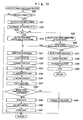
- Fig. 12 is a flowchart showing the jackpot game processing routine which is performed in the control circuit 60 of the gaming machine 10.
- This subroutine is a subroutine which is called and is executed at a predetermined timing in the control circuit 60.
- step S20 it is determined whether the holding number stored in the RAM 70 exceeds "0" or not.
- step S20 when it is determined that the holding number exceeds "0", the CPU 66 subtracts "1" from the holding number stored in the RAM 70 and stores the holding number after subtraction in the RAM 70 (step S21). At this point of time, the processing for decreasing the lit number of the holding lamps 33 by" 1" is also performed.
- the holding number can be added in step S11 in the subroutine shown in Fig. 11 even during this jackpot game is executed.
- step S22 it is determined whether the jackpot is activated or not. This determination of the activation of the jackpot is performed based on a lottery probability table which is preliminarily stored in the ROM 68 and the random number (random number for JP determination) sampled in step S12 in the subroutine shown in Fig. 11. As the result of the determination of the activation of the jackpot, it is determined whether the jackpot is activated or not.
- step S23 it is determined whether the result of the determination of the activation of the jackpot is the activation or the inactivation of the jackpot.
- the CPU 66 selects the stop mode (jackpot activation mode) of the short hand 21 and the long hand 22 at a point of time that the jackpot is finished based on a stop mode selection table which is preliminarily stored in the ROM 68 and the random number (random number for stop mode selection) sampled in step S12 in the subroutine shown in Fig. 11 (step S24).
- the rotation and the stop of the short hand 21 and the long hand 22 are executed such that the short hand 21 and the long hand 22 are stopped with the selected jackpot activation mode.
- the CPU 66 performs the sampling of the random number and selects the stop mode (miss mode) of the short hand 21 and the long hand 22 when the jackpot game is finished based on the sampled random number and the stop mode selection table (step S25).
- the rotation and the stopping of the short hand 21 and the long hand 22 are performed such that the short hand 21 and the long hand 22 are stopped at the selected miss mode.
- step S25 determines whether the miss mode which has been selected in step S25 is a stop mode showing a li-zhi (li-zhi mode) or not (step S26).
- the CPU 66 selects the rotation mode of the short hand 21 and the long hand 22 based on the random number (random number for selecting the rotation mode) which is sampled in step S12 in the subroutine shown in Fig. 11 and a rotation mode selection table which is preliminarily stored in the ROM 68 (step S27).
- the CPU 66 transmits a control signal to the motor drive control circuit 26a to make the motor drive control circuit 26a start the rotation of the short hand 21 and the long hand 22 (step S28) based on the selected rotation mode. Then, upon receiving the control signal, the motor drive control circuit 26a drives the stepping motors 21m, 22m so as to rotate the short hand 21 and the long hand 22.
- the CPU 66 waits until a predetermined period passes and continues the rotation of the short hand 21 and the long hand 22 in the rotation mode which is selected in step S27 (step S29). Thereafter, the CPU 66 transmits a control signal to the motor drive control circuit 26a to make the motor drive control circuit 26a stop the short hand 21 and the long hand 22 in the miss mode which is selected in step S25 (step S30) and this subroutine is finished. Then, upon receiving the control signal, the motor drive control circuit 26a stops the short hand 21 and the long hand 22 in the miss mode. This result implies that it is informed that the jackpot is not activated and the jackpot game is finished.
- the CPU 66 selects the rotation mode of the short hand 21 and the long hand 22 based on the random number which is sampled in step S12 in the subroutine shown in Fig. 11 (random number for selecting rotation mode) and a rotation mode selection table which is preliminarily stored in the ROM 68 (step S31).
- the CPU 66 transmits a control signal to the motor drive control circuit 26a to make the motor drive control circuit 26a start the rotation of the short hand 21 and the long hand 22 based on the selected rotation mode (step S32). Then, upon receiving the control signal, the motor drive control circuit 26a drives stepping motors 21m, 22m so as to rotate the short hand 21 and the long hand 22.
- the CPU 66 waits until a predetermined period has passes and continues the rotation of the short hand 21 and the long hand 22 in the rotation mode which is selected in step S31 (step S33). Thereafter, the CPU 66 transmits a control signal to the motor drive control circuit 26a to make the motor drive control circuit 26a stop the short hand 21 in such a manner that the li-zhi mode is assumed based on the jackpot activation mode which has been selected in step S24 or the miss mode which has been selected in step S25 (step S34). Then, upon receiving the control signal, the motor drive control circuit 26a stops the rotation of the short hand 21 in the li-zhi mode. This result informs the generation of li-zhi. At this time, the long hand 22 continues to be rotated.
- the CPU 66 transmits a command signal to the decorative lamps 24a to 24d and changes the light emitting colors or changes the lit patterns of the decorative lamps 24a to 24d (step S35).
- the CPU 66 waits until a predetermined period passes and continues the rotation of the long hand 22 in the selected rotation mode (step S36). Thereafter, the CPU 66 transmits a control signal to the motor drive control circuit 26a to make the motor drive control circuit 26a stop the long hand 22 in the jackpot activation mode which has been selected in step S24 or in the miss mode which has been selected in step S25 (step S37). Then, upon receiving the control signal, the motor drive control circuit 26a stops the long hand 22 in the jackpot activation mode or in the miss mode.
- step S38 the CPU 66 determines whether the stop mode of the short hand 21 and the long hand 22 is the jackpot activation mode or not, that is, whether the jackpot is activated or not in the jackpot game (step S38).
- the CPU 66 drives the open/close motor 27m and opens the lottery alarm display device 20 (the medal payout gate) to which the activation of the jackpot is informed (step S39). Thereafter, the CPU 66 performs the drive control of the payout device corresponding to the lottery alarm display device 20 (medal payout gate) to which the activation of the jackpot is informed among the payout devices 80 to 83 and pays out the medals accumulated in the medal accumulating device portion 30 to the push-out plate 35 (step S40).
- the payout devices 80 to 83 as shown in Fig. 6 to Fig. 9, respectively pay out the medals in different modes.
- control circuit 60 functions as a control means which performs the drive control of the payout devices in such a manner that the medal payout modes are different from each other for respective lottery alarm display devices 20 (medal payout gates) in response to the result of the JP lottery by the lottery means.
- the CPU 66 drives the open/close motor 27m to close the lottery alarm display device 20 (medal payout gate) (step S41) and this subroutine is finished.
- step S38 when it is determined that the jackpot is not activated in the jackpot game, the CPU 66 continuously stops the short hand 21 and the long hand 22 until a predetermined period passes (step S42) and, thereafter, this subroutine is finished.
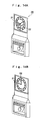
- Fig. 13A to 13C, Fig. 14A and 14b, Fig. 15A and Fig. 15b, Fig. 16A and Fig. 16B are views for explaining the game performed using the gaming machine 10.
- the player launches the medals into the gaming space 15 using the launching device 16.
- the player launches medals using the chucker 36 which tilts in the left-and-right directions within the opening 37 of the clock tower 13 as a target (see Fig. 13A).
- the medal which passes through the opening 37 falls in the push-out plate 35 below the opening 37 (see Fig. 13B).
- the JP lottery is performed and in response to the result of the JP lottery, the jackpot game is started in the lottery alarm display device 20 and the short hand 21 and the long hand 22 are rotated (see Fig. 14A).
- the jackpot is activated in the jackpot game (see Fig. 14B).
- the lottery alarm display device 20 medal payout gate
- the medals accumulated in the medal accumulating device portion 30 are paid out to the push-out plate 35 by the payout device.
- the payout devices 80 to 83 pay out the medals in respectively different modes.
- the medal payout mode of the payout device 80 is, as shown in Fig. 15A, a payout mode in which, after the lottery alarm display device 20 (medal payout gate) is opened, the rotary tray 801 appears while being rotated, three model bodies 803 which are mounted in an erected manner on the rotary tray 801 are rotated in response to the rotation of the rotary tray 801, and, further, the medals stacked on the rotary tray 801 are paid out onto the push-out plate 35.
- the medal payout mode of the payout device 81 is, as shown in Fig. 15B, a payout mode in which, after the lottery alarm display device 20 (medal payout gate) is opened, a model body 820 which imitates a dove appears and repeats the reciprocal movement in the fore-and-aft direction and, the medals accommodated in the medal accommodating portion 802a (not shown in the drawing) of the model body 820 are paid out onto the push-out plate 35.
- the medal payout mode of the payout device 82 is, as shown in Fig. 16A, a payout mode in which, after the lottery alarm display device 20 (medal payout gate) is opened, the medals stacked on the revolving tray 810 are paid out onto the push-out plate 35.
- the medal payout mode of the payout device 83 is, as shown in Fig. 16B, a payout mode in which, after the lottery alarm display device 20 (medal payout gate) is opened, the model body 830 including a doll and a box appears and repeats the reciprocal movement in the fore-and-aft direction. In this case, however, the medals are not paid out onto the push-out plate 35.
- the lottery alarm display devices 20 are mounted at the positions corresponding to respective launching devices 16 and a plurality of payout devices 80 to 83 which can perform medal payout in different payout modes are respectively incorporated into the respective lottery alarm display device 20 (medal payout gate). Accordingly, the medal payout mode differs depending on the launching device 16 to be used in playing the game and hence, the player can enjoy by watching the medal payout mode which changes each time the player plays the game. Accordingly, it is possible to strongly attract the player's interests.
- the medal payout modes according to the present invention are not limited to the examples shown in Fig. 15 and Fig. 16.
- the medal payout modes may include following payout modes.
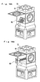
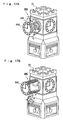
- Fig. 17A and Fig. 17B are perspective views schematically showing another example of the medal payout mode in an alternative embodiment of a gaming machine according to the present invention.
- the clock tower 13 is provided with lottery alarm display devices 220 (medal payout gates) on respective side surfaces thereof.
- the lottery alarm display device 220 (medal payout gates) is constituted such that each lottery alarm display device 220 is opened in such a manner that the lottery alarm display device 220 projects in the forward direction and a payout device 280 is mounted on a back surface of the lottery alarm display device 220.
- the payout device 280 is configured such that the payout device 280 is movable in the forward direction along with the opening of the lottery alarm display device 220.
- the payout device 280 has a cylindrical shape and is constituted such that the medals are accumulated therein, and a plurality of medal shooting openings 281 are formed in a side surface thereof.
- the medal payout mode of the payout device 280 is a payout mode in which, along with the opening of the lottery alarm display device 220 (medal payout gate), the medal payout device 280 is moved in the forward direction while being rotated and hence, the medals accumulated in the payout device 280 are paid out from the medal shooting opening 281.
- the clock tower 13 is provided with lottery alarm display devices 320 (medal payout gates) on the side surfaces thereof respectively.
- Each lottery alarm display device 320 (medal payout gates) is constituted such that the lottery alarm display device 320 is opened such that the lottery alarm display device 320 projects in the frontward direction and a payout device 380 is mounted on a back surface of the lottery alarm display device 320.
- the payout device 380 is constituted that the payout device 380 is moved in the forward direction along with the opening of the lottery alarm display device 320.
- the payout device 380 has a cylindrical shape and is configured to stock the medals therein. Although not shown in the drawing, a plurality of holes which allow the paying out of the medals are formed in the side surface thereof.
- the medal payout mode of the payout device 380 is a payout mode in which, upon opening the lottery alarm display device 320 (medal payout gate), the medal payout device 380 is moved forward while being rotated whereby the medals which are accumulated in the payout device 380 are paid out from the holes formed in the side surfaces of the medal payout device 380.
- the gaming machine may include:
- the payout device 80 which performs pays out the medals is selected.
- the payout device 80 is selected, after such a selection, four lottery alarm display device 20 (medal payout gates) and the payout devices 80 to 83 which are arranged in the inside of the lottery alarm display device 20 are rotated in the horizontal direction so that the payout devices 80 are moved to the position where the lottery alarm display device 20 (medal payout gate) to which the activation of the jackpot is informed is present. Thereafter, the medals are paid out from the payout device 80.
- the selection of the payout device for paying out the medals may be determined based on the result of the JP lottery or may be determined by performing other lottery.
- the explanation has been made with respect to the case in which the lottery alarm display device 20 functions as the medal payout gate.
- the medal payout gate and the lottery alarm display device are separate bodies.
- the medal payout modes according to the present invention are not limited to the above-mentioned examples. Further, in the gaming machine 10, all of the medal payout modes of four lottery alarm display devices 20 are different from each other. However, in the present invention, it is not always necessary that all of the medal payout modes of the plurality of medal payout gates are different from each other and some medal payout gates may adopt the same payout mode. Further, the number of kinds of medal payout modes is not specifically limited.
- each lottery alarm display device 20 (medal payout gates) is provided to the position corresponding to two launching devices 16.
- the number of launching devices corresponding to one medal payout gate is not specifically limited.
- the control circuit 60 which functions as the lottery means performs the JP lottery when the medal hits the chucker 36, that is, the control circuit 60 receives the detection signal from the medal detection sensor 38.
- the specific conditions which induce the lottery means to perform the JP lottery are not limited to the above-mentioned examples.
- the specific conditions to perform the JP lottery are not specifically limited. For example, a condition that a predetermined number of medals are launched from the launching device or a predetermined number of medals pass through the predetermined region in the gaming space may be named as such conditions.
Landscapes
- Physics & Mathematics (AREA)
- General Physics & Mathematics (AREA)
- Slot Machines And Peripheral Devices (AREA)
- Pinball Game Machines (AREA)
- Nitrogen And Oxygen Or Sulfur-Condensed Heterocyclic Ring Systems (AREA)
- Two-Way Televisions, Distribution Of Moving Picture Or The Like (AREA)
- Telephone Function (AREA)
- Eye Examination Apparatus (AREA)
Claims (7)
- Spielautomat (10), der ausgestaltet und angeordnet ist, um einem Spieler eine Möglichkeit zu geben Münzen zu erhalten, durch ein Auszahlen von Münzen, wenn eine vorbestimmte Bedingung erfüllt ist, wobei der Spielautomat (10) dadurch gekennzeichnet ist, dass er umfasst:eine Vielzahl von Auszahlvorrichtungen (80-83, 280, 380), die in der Lage sind die Münzen in einer Vielzahl von Auszahlmodi, die sich voneinander unterscheiden, auszuzahlen.
- Spielautomat nach Anspruch 1, wobei der Spielautomat (10) umfasst:einen Spielraum (15) zum Durchführen eines Spiels unter Benutzung der Münzen;eine Einführungsvorrichtung (16) zum Einführen der Münzen in den Spielraum;eine Gewinnspieleinheit, die ein Gewinnspiel durchführt, zum Bestimmen, ob die vorbestimmte Bedingung erfüllt ist; undeine Steuereinheit (60), die eine Antriebssteuerung der Auszahlvorrichtungen (80-83, 280, 380) durchführt, derart, dass sich der Münz-Auszahlmodus in Abhängigkeit einem Ergebnis des Gewinnspiels unterscheidet, das durch die Gewinnspieleinheit durchgeführt wurde.
- Spielautomat nach Anspruch 1 oder 2, wobei sich die Auszahlmodi bezüglich einer Menge der Münzen voneinander unterscheiden.
- Spielautomat nach einem der Ansprüche 1 bis 3, wobei, bei Erfüllung der vorbestimmten Bedingungen, gleichzeitig ein Jackpot aktiviert wird.
- Spielautomat nach einem der Ansprüche 1 bis 4, wobei der Spielautomat eine Vielzahl von Spielfeldern umfasst, wobei eines jeder der Vielzahl von Auszahlvorrichtungen entspricht.
- Spielautomat nach Anspruch 5, wobei der Spielautomat einen Ansammelvorrichtungsabschnitt (30) umfasst, in dem, bei Nutzung des Spielautomats, Münzen von jedem der Vielzahl von Spielfeldern gemeinsam angesammelt werden.
- Spielautomat nach Anspruch 6, wobei, bei Erfüllung der vorbestimmten Bedingungen, von jedem der Spielfelder angesammelte Münzen durch eine Ausgewählte von der Vielzahl der Auszahlvorrichtungen (80-83, 280, 380) an das Entsprechende von der Vielzahl der Spielfelder ausgezahlt werden.
Applications Claiming Priority (2)
| Application Number | Priority Date | Filing Date | Title |
|---|---|---|---|
| JP2003336356 | 2003-09-26 | ||
| JP2003336356A JP2005102731A (ja) | 2003-09-26 | 2003-09-26 | メダルゲーム機 |
Publications (2)
| Publication Number | Publication Date |
|---|---|
| EP1519335A1 EP1519335A1 (de) | 2005-03-30 |
| EP1519335B1 true EP1519335B1 (de) | 2007-08-15 |
Family
ID=34191539
Family Applications (1)
| Application Number | Title | Priority Date | Filing Date |
|---|---|---|---|
| EP04022797A Expired - Lifetime EP1519335B1 (de) | 2003-09-26 | 2004-09-24 | Spielgerät |
Country Status (8)
| Country | Link |
|---|---|
| US (1) | US20050070352A1 (de) |
| EP (1) | EP1519335B1 (de) |
| JP (1) | JP2005102731A (de) |
| CN (1) | CN100518870C (de) |
| AT (1) | ATE370478T1 (de) |
| AU (1) | AU2004214577A1 (de) |
| DE (1) | DE602004008176D1 (de) |
| ZA (1) | ZA200407772B (de) |
Families Citing this family (24)
| Publication number | Priority date | Publication date | Assignee | Title |
|---|---|---|---|---|
| US7253965B2 (en) | 2004-10-01 | 2007-08-07 | Nikon Corporation | Zoom lens system with vibration reduction |
| JP3944517B1 (ja) * | 2006-02-15 | 2007-07-11 | 株式会社コナミデジタルエンタテインメント | メダル遊技機 |
| US20080200229A1 (en) * | 2007-02-15 | 2008-08-21 | George Young | Apparatus and method for providing a game of chance at point of sale |
| JP5122222B2 (ja) * | 2007-09-12 | 2013-01-16 | 株式会社バンダイナムコゲームス | ゲーム装置 |
| GB2455745A (en) * | 2007-12-19 | 2009-06-24 | Game Concepts Ltd | Token shooting game |
| JP4934637B2 (ja) * | 2008-05-30 | 2012-05-16 | 株式会社コナミデジタルエンタテインメント | ゲームシステム並びにこれを構成する業務用ゲーム装置及び管理装置 |
| RU2381558C1 (ru) * | 2008-07-30 | 2010-02-10 | Петр Анатольевич Беликов | Игровой комплекс |
| JP5715745B2 (ja) * | 2008-08-25 | 2015-05-13 | 株式会社タイトー | マルチメダルプッシャーゲーム機 |
| JP5419628B2 (ja) * | 2009-10-09 | 2014-02-19 | 株式会社コナミデジタルエンタテインメント | ゲームシステム及びそのコンピュータプログラム |
| JP5618375B2 (ja) * | 2011-06-30 | 2014-11-05 | 株式会社大一商会 | 遊技機 |
| TW201308257A (zh) * | 2011-08-05 | 2013-02-16 | yun-lan Zheng | 電子感應投幣器 |
| AU2011221364B1 (en) * | 2011-09-07 | 2012-01-19 | Konami Gaming, Incorporated | Game machine, control method for use in the game machine, and computer program |
| JP6563733B2 (ja) * | 2015-08-07 | 2019-08-21 | 株式会社セガゲームス | プログラム、ゲーム装置及びサーバシステム |
| JP6099169B2 (ja) * | 2016-03-23 | 2017-03-22 | 株式会社大一商会 | 遊技機 |
| JP6099170B2 (ja) * | 2016-03-23 | 2017-03-22 | 株式会社大一商会 | 遊技機 |
| JP6099172B2 (ja) * | 2016-03-23 | 2017-03-22 | 株式会社大一商会 | 遊技機 |
| JP6099174B2 (ja) * | 2016-03-23 | 2017-03-22 | 株式会社大一商会 | 遊技機 |
| JP6099175B2 (ja) * | 2016-03-23 | 2017-03-22 | 株式会社大一商会 | 遊技機 |
| JP6099168B2 (ja) * | 2016-03-23 | 2017-03-22 | 株式会社大一商会 | 遊技機 |
| JP6099173B2 (ja) * | 2016-03-23 | 2017-03-22 | 株式会社大一商会 | 遊技機 |
| JP6099171B2 (ja) * | 2016-03-23 | 2017-03-22 | 株式会社大一商会 | 遊技機 |
| JP7594241B2 (ja) * | 2021-09-06 | 2024-12-04 | 株式会社セガ | メダルゲーム機 |
| JP7249394B1 (ja) * | 2021-11-05 | 2023-03-30 | 株式会社バンダイ | ゲーム装置、プログラム及びゲームシステム |
| CN115131921B (zh) * | 2022-07-01 | 2024-08-27 | 广州骏霖文化科技有限公司 | 可任意指定方位的投放币装置 |
Family Cites Families (11)
| Publication number | Priority date | Publication date | Assignee | Title |
|---|---|---|---|---|
| US5016880A (en) * | 1990-02-15 | 1991-05-21 | Harald Berge | Coin or token-released gaming machine |
| US5397125A (en) * | 1993-12-15 | 1995-03-14 | Anchor Coin, Inc. | Gaming device with payouts of multiple forms |
| JP3450454B2 (ja) * | 1994-08-26 | 2003-09-22 | アルゼ株式会社 | 遊戯装置 |
| US6168522B1 (en) * | 1998-03-31 | 2001-01-02 | Walker Digital, Llc | Method and apparatus for operating a gaming device to dispense a specified amount |
| US6003504A (en) * | 1998-08-20 | 1999-12-21 | Npf Limited | Paint ball gun |
| JP3882876B2 (ja) * | 1998-11-13 | 2007-02-21 | 株式会社セガ | メダルゲーム装置 |
| US6358147B1 (en) * | 1999-06-23 | 2002-03-19 | Wms Gaming Inc. | Gaming machine with multiple payoff modes and award presentation schemes |
| JP3790085B2 (ja) * | 1999-08-31 | 2006-06-28 | 株式会社バンダイナムコゲームス | メダルゲーム装置 |
| JP2001353354A (ja) * | 2000-06-14 | 2001-12-25 | Namco Ltd | ゲームシステム及び情報記憶媒体 |
| JP3313105B2 (ja) * | 2000-09-25 | 2002-08-12 | コナミ株式会社 | 射的ゲーム装置及び射的ゲームシステム |
| JP2002331162A (ja) * | 2001-05-08 | 2002-11-19 | Konami Co Ltd | 遊技機 |
-
2003
- 2003-09-26 JP JP2003336356A patent/JP2005102731A/ja not_active Withdrawn
-
2004
- 2004-09-24 CN CNB2004100752796A patent/CN100518870C/zh not_active Expired - Fee Related
- 2004-09-24 EP EP04022797A patent/EP1519335B1/de not_active Expired - Lifetime
- 2004-09-24 US US10/948,130 patent/US20050070352A1/en not_active Abandoned
- 2004-09-24 DE DE602004008176T patent/DE602004008176D1/de not_active Expired - Fee Related
- 2004-09-24 AT AT04022797T patent/ATE370478T1/de not_active IP Right Cessation
- 2004-09-24 AU AU2004214577A patent/AU2004214577A1/en not_active Abandoned
- 2004-09-27 ZA ZA2004/07772A patent/ZA200407772B/en unknown
Also Published As
| Publication number | Publication date |
|---|---|
| CN1607020A (zh) | 2005-04-20 |
| JP2005102731A (ja) | 2005-04-21 |
| ATE370478T1 (de) | 2007-09-15 |
| US20050070352A1 (en) | 2005-03-31 |
| CN100518870C (zh) | 2009-07-29 |
| ZA200407772B (en) | 2005-07-27 |
| EP1519335A1 (de) | 2005-03-30 |
| AU2004214577A1 (en) | 2005-04-14 |
| DE602004008176D1 (de) | 2007-09-27 |
Similar Documents
| Publication | Publication Date | Title |
|---|---|---|
| EP1519335B1 (de) | Spielgerät | |
| US5803451A (en) | Arcade game having multiple score indicators | |
| US5676371A (en) | Arcade games | |
| JP6570106B2 (ja) | 遊技機 | |
| JP4772296B2 (ja) | ゲーム機 | |
| JP2007301201A (ja) | 遊技機 | |
| JP4621836B2 (ja) | 遊技機 | |
| JP2007195675A (ja) | 遊技機 | |
| US20050087926A1 (en) | Gaming machine | |
| EP1530175B1 (de) | Spielgerät | |
| JP2790670B2 (ja) | 遊技機 | |
| JPH0928919A (ja) | メダル打出遊技機 | |
| JPS62152488A (ja) | 弾球遊技機 | |
| JP5846827B2 (ja) | 遊技機 | |
| JP2005102732A (ja) | メダルゲーム機 | |
| JP4840764B2 (ja) | 遊技機 | |
| JP2764443B2 (ja) | 弾球遊技機 | |
| JP2000197745A (ja) | パチンコ遊技機 | |
| JP2805087B2 (ja) | 弾球遊技機 | |
| JP6085412B2 (ja) | 遊技機ユニット | |
| US20050067779A1 (en) | Gaming machine | |
| JP4730736B2 (ja) | 遊技機 | |
| WO2007024923A2 (en) | Gaming device with transport device and method of use | |
| JPS6324703B2 (de) | ||
| JP2004167279A (ja) | パチンコ遊技機 |
Legal Events
| Date | Code | Title | Description |
|---|---|---|---|
| PUAI | Public reference made under article 153(3) epc to a published international application that has entered the european phase |
Free format text: ORIGINAL CODE: 0009012 |
|
| AK | Designated contracting states |
Kind code of ref document: A1 Designated state(s): AT BE BG CH CY CZ DE DK EE ES FI FR GB GR HU IE IT LI LU MC NL PL PT RO SE SI SK TR |
|
| AX | Request for extension of the european patent |
Extension state: AL HR LT LV MK |
|
| 17P | Request for examination filed |
Effective date: 20050831 |
|
| AKX | Designation fees paid |
Designated state(s): AT BE BG CH CY CZ DE DK EE ES FI FR GB GR HU IE IT LI LU MC NL PL PT RO SE SI SK TR |
|
| GRAP | Despatch of communication of intention to grant a patent |
Free format text: ORIGINAL CODE: EPIDOSNIGR1 |
|
| RIN1 | Information on inventor provided before grant (corrected) |
Inventor name: HATTORI, TAKANORIC/O ARUZE CORP. |
|
| GRAS | Grant fee paid |
Free format text: ORIGINAL CODE: EPIDOSNIGR3 |
|
| GRAA | (expected) grant |
Free format text: ORIGINAL CODE: 0009210 |
|
| AK | Designated contracting states |
Kind code of ref document: B1 Designated state(s): AT BE BG CH CY CZ DE DK EE ES FI FR GB GR HU IE IT LI LU MC NL PL PT RO SE SI SK TR |
|
| REG | Reference to a national code |
Ref country code: GB Ref legal event code: FG4D |
|
| RIN1 | Information on inventor provided before grant (corrected) |
Inventor name: HATTORI, TAKANORIC/O ARUZE CORP., |
|
| REG | Reference to a national code |
Ref country code: CH Ref legal event code: EP |
|
| REG | Reference to a national code |
Ref country code: IE Ref legal event code: FG4D |
|
| REF | Corresponds to: |
Ref document number: 602004008176 Country of ref document: DE Date of ref document: 20070927 Kind code of ref document: P |
|
| PG25 | Lapsed in a contracting state [announced via postgrant information from national office to epo] |
Ref country code: ES Free format text: LAPSE BECAUSE OF FAILURE TO SUBMIT A TRANSLATION OF THE DESCRIPTION OR TO PAY THE FEE WITHIN THE PRESCRIBED TIME-LIMIT Effective date: 20071126 Ref country code: NL Free format text: LAPSE BECAUSE OF FAILURE TO SUBMIT A TRANSLATION OF THE DESCRIPTION OR TO PAY THE FEE WITHIN THE PRESCRIBED TIME-LIMIT Effective date: 20070815 Ref country code: FI Free format text: LAPSE BECAUSE OF FAILURE TO SUBMIT A TRANSLATION OF THE DESCRIPTION OR TO PAY THE FEE WITHIN THE PRESCRIBED TIME-LIMIT Effective date: 20070815 Ref country code: BG Free format text: LAPSE BECAUSE OF FAILURE TO SUBMIT A TRANSLATION OF THE DESCRIPTION OR TO PAY THE FEE WITHIN THE PRESCRIBED TIME-LIMIT Effective date: 20071115 |
|
| NLV1 | Nl: lapsed or annulled due to failure to fulfill the requirements of art. 29p and 29m of the patents act | ||
| PG25 | Lapsed in a contracting state [announced via postgrant information from national office to epo] |
Ref country code: CH Free format text: LAPSE BECAUSE OF FAILURE TO SUBMIT A TRANSLATION OF THE DESCRIPTION OR TO PAY THE FEE WITHIN THE PRESCRIBED TIME-LIMIT Effective date: 20070815 Ref country code: PL Free format text: LAPSE BECAUSE OF FAILURE TO SUBMIT A TRANSLATION OF THE DESCRIPTION OR TO PAY THE FEE WITHIN THE PRESCRIBED TIME-LIMIT Effective date: 20070815 Ref country code: LI Free format text: LAPSE BECAUSE OF FAILURE TO SUBMIT A TRANSLATION OF THE DESCRIPTION OR TO PAY THE FEE WITHIN THE PRESCRIBED TIME-LIMIT Effective date: 20070815 Ref country code: AT Free format text: LAPSE BECAUSE OF FAILURE TO SUBMIT A TRANSLATION OF THE DESCRIPTION OR TO PAY THE FEE WITHIN THE PRESCRIBED TIME-LIMIT Effective date: 20070815 |
|
| REG | Reference to a national code |
Ref country code: CH Ref legal event code: PL |
|
| PG25 | Lapsed in a contracting state [announced via postgrant information from national office to epo] |
Ref country code: BE Free format text: LAPSE BECAUSE OF FAILURE TO SUBMIT A TRANSLATION OF THE DESCRIPTION OR TO PAY THE FEE WITHIN THE PRESCRIBED TIME-LIMIT Effective date: 20070815 |
|
| EN | Fr: translation not filed | ||
| PG25 | Lapsed in a contracting state [announced via postgrant information from national office to epo] |
Ref country code: DK Free format text: LAPSE BECAUSE OF FAILURE TO SUBMIT A TRANSLATION OF THE DESCRIPTION OR TO PAY THE FEE WITHIN THE PRESCRIBED TIME-LIMIT Effective date: 20070815 Ref country code: GR Free format text: LAPSE BECAUSE OF FAILURE TO SUBMIT A TRANSLATION OF THE DESCRIPTION OR TO PAY THE FEE WITHIN THE PRESCRIBED TIME-LIMIT Effective date: 20071116 Ref country code: MC Free format text: LAPSE BECAUSE OF NON-PAYMENT OF DUE FEES Effective date: 20070930 |
|
| PG25 | Lapsed in a contracting state [announced via postgrant information from national office to epo] |
Ref country code: CZ Free format text: LAPSE BECAUSE OF FAILURE TO SUBMIT A TRANSLATION OF THE DESCRIPTION OR TO PAY THE FEE WITHIN THE PRESCRIBED TIME-LIMIT Effective date: 20070815 Ref country code: SK Free format text: LAPSE BECAUSE OF FAILURE TO SUBMIT A TRANSLATION OF THE DESCRIPTION OR TO PAY THE FEE WITHIN THE PRESCRIBED TIME-LIMIT Effective date: 20070815 Ref country code: PT Free format text: LAPSE BECAUSE OF FAILURE TO SUBMIT A TRANSLATION OF THE DESCRIPTION OR TO PAY THE FEE WITHIN THE PRESCRIBED TIME-LIMIT Effective date: 20080115 |
|
| PLBE | No opposition filed within time limit |
Free format text: ORIGINAL CODE: 0009261 |
|
| STAA | Information on the status of an ep patent application or granted ep patent |
Free format text: STATUS: NO OPPOSITION FILED WITHIN TIME LIMIT |
|
| PG25 | Lapsed in a contracting state [announced via postgrant information from national office to epo] |
Ref country code: RO Free format text: LAPSE BECAUSE OF FAILURE TO SUBMIT A TRANSLATION OF THE DESCRIPTION OR TO PAY THE FEE WITHIN THE PRESCRIBED TIME-LIMIT Effective date: 20070815 Ref country code: SE Free format text: LAPSE BECAUSE OF FAILURE TO SUBMIT A TRANSLATION OF THE DESCRIPTION OR TO PAY THE FEE WITHIN THE PRESCRIBED TIME-LIMIT Effective date: 20071115 |
|
| 26N | No opposition filed |
Effective date: 20080516 |
|
| PG25 | Lapsed in a contracting state [announced via postgrant information from national office to epo] |
Ref country code: DE Free format text: LAPSE BECAUSE OF NON-PAYMENT OF DUE FEES Effective date: 20080401 |
|
| PG25 | Lapsed in a contracting state [announced via postgrant information from national office to epo] |
Ref country code: IE Free format text: LAPSE BECAUSE OF NON-PAYMENT OF DUE FEES Effective date: 20070924 |
|
| PG25 | Lapsed in a contracting state [announced via postgrant information from national office to epo] |
Ref country code: EE Free format text: LAPSE BECAUSE OF FAILURE TO SUBMIT A TRANSLATION OF THE DESCRIPTION OR TO PAY THE FEE WITHIN THE PRESCRIBED TIME-LIMIT Effective date: 20070815 |
|
| PG25 | Lapsed in a contracting state [announced via postgrant information from national office to epo] |
Ref country code: FR Free format text: LAPSE BECAUSE OF NON-PAYMENT OF DUE FEES Effective date: 20070930 |
|
| PG25 | Lapsed in a contracting state [announced via postgrant information from national office to epo] |
Ref country code: SI Free format text: LAPSE BECAUSE OF FAILURE TO SUBMIT A TRANSLATION OF THE DESCRIPTION OR TO PAY THE FEE WITHIN THE PRESCRIBED TIME-LIMIT Effective date: 20070815 |
|
| PG25 | Lapsed in a contracting state [announced via postgrant information from national office to epo] |
Ref country code: CY Free format text: LAPSE BECAUSE OF FAILURE TO SUBMIT A TRANSLATION OF THE DESCRIPTION OR TO PAY THE FEE WITHIN THE PRESCRIBED TIME-LIMIT Effective date: 20070815 |
|
| PG25 | Lapsed in a contracting state [announced via postgrant information from national office to epo] |
Ref country code: LU Free format text: LAPSE BECAUSE OF NON-PAYMENT OF DUE FEES Effective date: 20070924 |
|
| PG25 | Lapsed in a contracting state [announced via postgrant information from national office to epo] |
Ref country code: TR Free format text: LAPSE BECAUSE OF FAILURE TO SUBMIT A TRANSLATION OF THE DESCRIPTION OR TO PAY THE FEE WITHIN THE PRESCRIBED TIME-LIMIT Effective date: 20070815 Ref country code: HU Free format text: LAPSE BECAUSE OF FAILURE TO SUBMIT A TRANSLATION OF THE DESCRIPTION OR TO PAY THE FEE WITHIN THE PRESCRIBED TIME-LIMIT Effective date: 20080216 |
|
| PG25 | Lapsed in a contracting state [announced via postgrant information from national office to epo] |
Ref country code: IT Free format text: LAPSE BECAUSE OF NON-PAYMENT OF DUE FEES Effective date: 20070930 |
|
| PGFP | Annual fee paid to national office [announced via postgrant information from national office to epo] |
Ref country code: GB Payment date: 20140919 Year of fee payment: 11 |
|
| GBPC | Gb: european patent ceased through non-payment of renewal fee |
Effective date: 20150924 |
|
| PG25 | Lapsed in a contracting state [announced via postgrant information from national office to epo] |
Ref country code: GB Free format text: LAPSE BECAUSE OF NON-PAYMENT OF DUE FEES Effective date: 20150924 |