EP1518820A1 - Entnahmearmatur aus Kunststoff für Transport- und Lagerbehälter für Flüssigkeiten - Google Patents
Entnahmearmatur aus Kunststoff für Transport- und Lagerbehälter für Flüssigkeiten Download PDFInfo
- Publication number
- EP1518820A1 EP1518820A1 EP04021986A EP04021986A EP1518820A1 EP 1518820 A1 EP1518820 A1 EP 1518820A1 EP 04021986 A EP04021986 A EP 04021986A EP 04021986 A EP04021986 A EP 04021986A EP 1518820 A1 EP1518820 A1 EP 1518820A1
- Authority
- EP
- European Patent Office
- Prior art keywords
- inlet
- nozzle
- liquid container
- housing
- outlet
- Prior art date
- Legal status (The legal status is an assumption and is not a legal conclusion. Google has not performed a legal analysis and makes no representation as to the accuracy of the status listed.)
- Granted
Links
- 239000007788 liquid Substances 0.000 title claims abstract description 22
- 229920003023 plastic Polymers 0.000 title claims abstract description 13
- 239000004033 plastic Substances 0.000 title claims abstract description 13
- 238000000071 blow moulding Methods 0.000 claims description 2
- 238000002347 injection Methods 0.000 claims description 2
- 239000007924 injection Substances 0.000 claims description 2
- 238000003780 insertion Methods 0.000 claims description 2
- 230000037431 insertion Effects 0.000 claims description 2
- 229920001903 high density polyethylene Polymers 0.000 description 2
- 239000002184 metal Substances 0.000 description 2
- 238000007789 sealing Methods 0.000 description 2
- 238000004891 communication Methods 0.000 description 1
- 238000011161 development Methods 0.000 description 1
- 230000018109 developmental process Effects 0.000 description 1
- 239000000945 filler Substances 0.000 description 1
- 239000004700 high-density polyethylene Substances 0.000 description 1
- 238000001746 injection moulding Methods 0.000 description 1
- 238000009434 installation Methods 0.000 description 1
Images


Classifications
-
- B—PERFORMING OPERATIONS; TRANSPORTING
- B67—OPENING, CLOSING OR CLEANING BOTTLES, JARS OR SIMILAR CONTAINERS; LIQUID HANDLING
- B67D—DISPENSING, DELIVERING OR TRANSFERRING LIQUIDS, NOT OTHERWISE PROVIDED FOR
- B67D7/00—Apparatus or devices for transferring liquids from bulk storage containers or reservoirs into vehicles or into portable containers, e.g. for retail sale purposes
- B67D7/06—Details or accessories
- B67D7/32—Arrangements of safety or warning devices; Means for preventing unauthorised delivery of liquid
- B67D7/34—Means for preventing unauthorised delivery of liquid
- B67D7/344—Means for preventing unauthorised delivery of liquid by checking a correct coupling or coded information
-
- B—PERFORMING OPERATIONS; TRANSPORTING
- B67—OPENING, CLOSING OR CLEANING BOTTLES, JARS OR SIMILAR CONTAINERS; LIQUID HANDLING
- B67D—DISPENSING, DELIVERING OR TRANSFERRING LIQUIDS, NOT OTHERWISE PROVIDED FOR
- B67D3/00—Apparatus or devices for controlling flow of liquids under gravity from storage containers for dispensing purposes
- B67D3/04—Liquid-dispensing taps or cocks adapted to seal and open tapping holes of casks, e.g. for beer
-
- F—MECHANICAL ENGINEERING; LIGHTING; HEATING; WEAPONS; BLASTING
- F16—ENGINEERING ELEMENTS AND UNITS; GENERAL MEASURES FOR PRODUCING AND MAINTAINING EFFECTIVE FUNCTIONING OF MACHINES OR INSTALLATIONS; THERMAL INSULATION IN GENERAL
- F16L—PIPES; JOINTS OR FITTINGS FOR PIPES; SUPPORTS FOR PIPES, CABLES OR PROTECTIVE TUBING; MEANS FOR THERMAL INSULATION IN GENERAL
- F16L19/00—Joints in which sealing surfaces are pressed together by means of a member, e.g. a swivel nut, screwed on or into one of the joint parts
- F16L19/005—Joints in which sealing surfaces are pressed together by means of a member, e.g. a swivel nut, screwed on or into one of the joint parts comprising locking means for the threaded member
-
- F—MECHANICAL ENGINEERING; LIGHTING; HEATING; WEAPONS; BLASTING
- F16—ENGINEERING ELEMENTS AND UNITS; GENERAL MEASURES FOR PRODUCING AND MAINTAINING EFFECTIVE FUNCTIONING OF MACHINES OR INSTALLATIONS; THERMAL INSULATION IN GENERAL
- F16L—PIPES; JOINTS OR FITTINGS FOR PIPES; SUPPORTS FOR PIPES, CABLES OR PROTECTIVE TUBING; MEANS FOR THERMAL INSULATION IN GENERAL
- F16L19/00—Joints in which sealing surfaces are pressed together by means of a member, e.g. a swivel nut, screwed on or into one of the joint parts
- F16L19/02—Pipe ends provided with collars or flanges, integral with the pipe or not, pressed together by a screwed member
- F16L19/0237—Pipe ends provided with collars or flanges, integral with the pipe or not, pressed together by a screwed member specially adapted for use with attachments, e.g. reduction units, T-pieces, bends or the like
-
- Y—GENERAL TAGGING OF NEW TECHNOLOGICAL DEVELOPMENTS; GENERAL TAGGING OF CROSS-SECTIONAL TECHNOLOGIES SPANNING OVER SEVERAL SECTIONS OF THE IPC; TECHNICAL SUBJECTS COVERED BY FORMER USPC CROSS-REFERENCE ART COLLECTIONS [XRACs] AND DIGESTS
- Y10—TECHNICAL SUBJECTS COVERED BY FORMER USPC
- Y10T—TECHNICAL SUBJECTS COVERED BY FORMER US CLASSIFICATION
- Y10T137/00—Fluid handling
- Y10T137/0318—Processes
- Y10T137/0402—Cleaning, repairing, or assembling
- Y10T137/0491—Valve or valve element assembling, disassembling, or replacing
- Y10T137/0508—Ball valve or rotary ball valve
-
- Y—GENERAL TAGGING OF NEW TECHNOLOGICAL DEVELOPMENTS; GENERAL TAGGING OF CROSS-SECTIONAL TECHNOLOGIES SPANNING OVER SEVERAL SECTIONS OF THE IPC; TECHNICAL SUBJECTS COVERED BY FORMER USPC CROSS-REFERENCE ART COLLECTIONS [XRACs] AND DIGESTS
- Y10—TECHNICAL SUBJECTS COVERED BY FORMER USPC
- Y10T—TECHNICAL SUBJECTS COVERED BY FORMER US CLASSIFICATION
- Y10T137/00—Fluid handling
- Y10T137/598—With repair, tapping, assembly, or disassembly means
- Y10T137/6031—Assembling or disassembling rotary valve
- Y10T137/6035—Rotary ball valve
Definitions
- the invention relates to a removal fitting made of plastic, in particular a flap or ball valve, for transport and Plastic storage containers for liquids, with one Valve body, which has an inlet neck, which means a union nut to the externally threaded Outlet nozzle of the liquid container can be screwed on, and which has an outlet connection (DE 101 24 681 A1).
- the generic type are used in liquid containers, with a pallet base, a replaceable one Plastic inner container with four side walls, one lower and one upper bottom, a filler neck and a Outlet and with a surrounding the inner container Outer jacket are equipped, as a metal jacket or Grid sheath consisting of vertical and horizontal bars Metal is formed.
- the invention is based on the object, the generic Removal fitting with a view to the greatest possible Anti-rotation to prevent damage to the To further develop the seal of the valve during assembly.
- the subclaims include advantageous and expedient Further developments of the removal fitting.
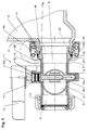
- Hahn housing 2 of the valve cock 1 takes a disc 3 for opening and closing the central Flow opening 4 of the housing chamber 5, which with the Inlet 6 of a welded to the valve body 2 Einlaufstutzens 7 and the outlet channel 8 of the outlet nozzle. 9 of the valve body 2 is in communication.
- the disc 3 is eccentrically attached to a rotary shaft 10, whose one end 10a is rotatably mounted in the valve housing 2 and the other end 10b via a bearing neck 11 from the valve body 2 to the outside protrudes.
- the rotary shaft 10 is by means of sealing rings 12 in the Bearing 11 sealed to the outside.
- On the from the Hahngefelduse 2 outstanding end 10b of the rotary shaft 10 of Valve disc 3 is a handle 13 for opening and closing the flap cock 1 attached.
- the flap valve 1 is by means of a union nut 14 on the Outlet 15 of a liquid container 16, e.g. one Plastic inner container of a pallet container, attached, wherein the liquid container 16 with the one with an external thread 17 provided outlet 9 in one piece by blow molding is made.
- a liquid container 16 e.g. one Plastic inner container of a pallet container
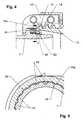
- the flap valve 1 has an anti-rotation with a on the inlet connection 7 of the valve housing 2 arranged outside Cam ring 18, the locking cams 19 when pulling the Einlaufstutzens 7 of the valve body 2 in the outlet nozzle 15th of the liquid container 16 by screwing on the Inlet 7 of the valve body 2 held captive Union nut 14, with an annular shoulder 20 on a collar 21 of the inlet nozzle 7 attacks, on the outlet nozzle 15 of the Liquid container 16 with the locking cams 23 on the outside End 15 a of the outlet nozzle 15 of the container 16 integrally formed inner cam ring 22 locked.
- the flap valve 1 is by means of a on the inlet nozzle. 7 of the cock housing 2 seated sealing ring 24, the at Screwing the union nut 14 on the outlet nozzle 15 of Liquid container 16 between the collar 21 of the Einlaufstutzens 7 of the valve housing 2 and the outer end 15 a the discharge nozzle 15 of the liquid container 16 is clamped is sealed against the container.
- FIGS 6 and 3 show a flap valve 1 with a Another embodiment of an anti-rotation with a Adapter ring 25, distributed over the circumference inner and outer Latching cams 26, 27, wherein on the insertion end 7a of the Inlet neck 7 of the valve body 2 retractable adapter ring 25 with the inner locking cam 26 in corresponding longitudinal grooves 28th in the outer jacket 29 of the inlet nozzle 7 of the valve housing second engages and the adapter ring 25 when pulling the Einlaufstutzens 7 of the valve body 2 in the outlet nozzle 15th of the liquid container 16 by screwing on the Inlet 7 of the valve body 2 held captive Union nut 14 on the outlet nozzle 15 of the Liquid container 16 with the outer locking cam 27 in corresponding longitudinal grooves 30 in the inner shell 31 of the Outlet nozzle 15 of the container 16 engages.
Abstract
Description
- Fig. 1
- eine Längsschnittdarstellung eines Klappenhahns mit einer ersten Ausführungsform einer Verdrehsicherung,
- Fig. 2
- eine Stirnansicht des Klappenhahns,
- Fig. 3
- den Einlaufstutzen des Hahngehäuses des Klappenhahns nach den Figuren 1 und 2 in perspektivischer Darstellung,
- Fig. 4
- eine vergrößerte Teildarstellung der Verdrehsicherung gemäß Ausschnitt IV der Fig. 1,
- Fig. 5
- einen Querschnitt der Verdrehsicherung gemäß Linie V-V der Fig. IV und
- Fig. 6
- eine Längsschnittdarstellung eines Klappenhahns mit einer weiteren Ausführungsform der Verdrehsicherung.
Claims (6)
- Entnahmearmatur aus Kunststoff, insbesondere Klappen- oder Kugelhahn, für Transport- und Lagerbehälter aus Kunststoff für Flüssigkeiten, mit einem Armaturengehäuse, das einen Einlaufstutzen aufweist, der mittels einer Überwurfmutter an den mit einem Außengewinde versehenen Auslaufstutzen des Flüssigkeitsbehälters anschraubbar ist, und das einen Auslaufstutzen besitzt, gekennzeichnet durch eine Verdrehsicherung mit einem auf dem Einlaufstutzen (7) des Armaturengehäuses (Hahngehäuse 2) angeordneten äußeren Nockenkranz (18), dessen Rastnocken (19) beim Einziehen des Einlaufstutzens (7) des Hahngehäuses (2) in den Auslaufstutzen (15) des Flüssigkeitsbehälters (16) durch das Aufschrauben der auf dem Einlaufstutzen (7) des Hahngehäuses (2) unverlierbar gehaltenen Überwurfmutter (14) auf den Auslaufstutzen (15) des Flüssigkeitsbehälters (16) mit den Rastnocken (23) eines am äußeren Ende (15a) des Auslaufstutzens (15) des Behälters (16) angeformten inneren Nockenkranzes (22) verrastet.
- Entnahmearmatur nach Anspruch 1, dadurch gekennzeichnet, daß der Einlaufstutzen (7) des Hahngehäuses (2) mit dem Nockenkranz (18) als Kunststoff-Spritzgußteil gefertigt und mit dem Hahngehäuse (2) verschweißt ist.
- Entnahmearmatur nach Anspruch 1 und 2, dadurch gekennzeichnet, daß der Flüssigkeitsbehälter (16) mit dem mit einem Außengewinde (17) versehenen Auslaufstutzen (15) einteilig durch Blasformen hergestellt ist.
- Entnahmearmatur nach dem Oberbegriff des Anspruchs 1, gekennzeichnet durch eine Verdrehsicherung mit einem Adapterring (25), der über den Umfang verteilt innere und äußere Rastnocken (26, 27) aufweist, wobei der auf das Einsetzende (7a) des Einlaufstutzens (7) des Hahngehäuses (2) aufschiebbare Adapterring (25) mit den inneren Rastnocken (26) in entsprechende Längsnuten (28) im Außenmantel (29) des Einlaufstutzens (7) des Hahngehäuses (2) eingreift und der Adapterring (25) beim Einziehen des Einlaufsstutzens (7) des Hahngehäuses (2) in den Auslaufstutzen (15) des Flüssigkeitsbehälters (16) durch Aufschrauben der auf dem Einlaufstutzen (7) des Hahngehäuses (2) unverlierbar gehaltenen Überwurfmutter (14) auf den Auslaufstutzen (15) des Flüssigkeitsbehälters (16) mit den äußeren Rastnocken (27) in entsprechende Längsnuten (30) im Innenmantel (31) des Auslaufstutzens (15) des Behälters (16) in Eingriff gelangt.
- Entnahmearmatur nach Anspruch 4, dadurch gekennzeichnet, daß der als Kunststoff-Spritzgußteil vorgefertigte, mit einem Außengewinde (17) versehene Auslaufstutzen (15) an den Flüssigkeitsbehälter (16) angeblasen ist.
- Entnahmearmatur nach dem Oberbegriff des Anspruchs 1, gekennzeichnet durch einen auf dem Einlaufstutzen (7) des Hahngehäuses (2) angeordneten äußeren Nockenkranz (18) und im Außenmantel (29) des Einlaufstutzens (7) ausgebildete Längsnuten (28) zur wahlweisen Anbringung der Verdrehsicherung nach Anspruch 1 oder 4.
Priority Applications (1)
| Application Number | Priority Date | Filing Date | Title |
|---|---|---|---|
| PL04021986T PL1518820T3 (pl) | 2003-09-27 | 2004-09-16 | Armatura czerpalna z tworzywa sztucznego dla zbiorników transportowo-magazynowych dla cieczy |
Applications Claiming Priority (2)
| Application Number | Priority Date | Filing Date | Title |
|---|---|---|---|
| DE10344962 | 2003-09-27 | ||
| DE2003144962 DE10344962B3 (de) | 2003-09-27 | 2003-09-27 | Entnahmearmatur aus Kunststoff für Transport- und Lagerbehälter für Flüssigkeiten |
Publications (2)
| Publication Number | Publication Date |
|---|---|
| EP1518820A1 true EP1518820A1 (de) | 2005-03-30 |
| EP1518820B1 EP1518820B1 (de) | 2008-12-03 |
Family
ID=34177993
Family Applications (1)
| Application Number | Title | Priority Date | Filing Date |
|---|---|---|---|
| EP20040021986 Active EP1518820B1 (de) | 2003-09-27 | 2004-09-16 | Entnahmearmatur aus Kunststoff für Transport- und Lagerbehälter für Flüssigkeiten |
Country Status (17)
| Country | Link |
|---|---|
| US (1) | US7712639B2 (de) |
| EP (1) | EP1518820B1 (de) |
| JP (1) | JP4113868B2 (de) |
| CN (2) | CN100376833C (de) |
| AR (1) | AR046024A1 (de) |
| AT (1) | ATE416145T1 (de) |
| AU (1) | AU2004214588B2 (de) |
| BR (1) | BRPI0404194B1 (de) |
| DE (2) | DE10344962B3 (de) |
| DK (1) | DK1518820T3 (de) |
| ES (1) | ES2318226T3 (de) |
| MX (1) | MXPA04009262A (de) |
| MY (1) | MY136495A (de) |
| NO (3) | NO332379B1 (de) |
| PL (1) | PL1518820T3 (de) |
| RU (1) | RU2275322C1 (de) |
| ZA (1) | ZA200407430B (de) |
Cited By (2)
| Publication number | Priority date | Publication date | Assignee | Title |
|---|---|---|---|---|
| EP1975484A2 (de) | 2007-03-28 | 2008-10-01 | O.M.C.E. di Rocchetti Amleto S.p.A. | System zur sicheren Befestigung von Kappen, Ventilen und dergleichen an Behältern |
| DE102008038544A1 (de) * | 2008-08-20 | 2010-03-04 | Protechna S.A. | Entnahmearmatur mit einem Armaturengehäuse aus Kunststoff für Transport- und Lagerbehälter für Flüssigkeiten |
Families Citing this family (12)
| Publication number | Priority date | Publication date | Assignee | Title |
|---|---|---|---|---|
| JP2007022544A (ja) * | 2005-07-12 | 2007-02-01 | Chiyoda Chemical Kk | 取出装置付容器、及び該取出装置付容器を洗浄する方法 |
| CH700100B1 (de) * | 2008-12-12 | 2013-02-28 | Inficon Gmbh | Ventil. |
| US20130292412A1 (en) * | 2012-05-04 | 2013-11-07 | International Paper Company | Bulk bin and bag dispensing apparatus |
| US9683351B2 (en) * | 2013-06-19 | 2017-06-20 | Chin-Ming Hsieh | Opening for metal faucet |
| FR3044735B1 (fr) * | 2015-12-08 | 2017-12-08 | Daher Valves | Vanne pour cylindre de stockage uf6 |
| DE102016200206B4 (de) * | 2016-01-11 | 2020-08-13 | Protechna S.A. | Entnahmearmatur für flüssigkeitsbehälter |
| US10354828B1 (en) | 2016-07-08 | 2019-07-16 | Triad National Security, Llc | Photocathodes with protective in-situ graphene gas barrier films and method of making the same |
| US10679816B1 (en) * | 2016-07-08 | 2020-06-09 | Triad National Security, Llc | Thermionic cathode with a graphene sealing layer and method of making the same |
| DE102018108755B3 (de) * | 2018-04-12 | 2019-08-14 | Protechna S.A. | Sicherungseinrichtung für eine Entnahmearmatur |
| CN110329643B (zh) * | 2019-06-13 | 2021-05-11 | 江西奕方农业科技有限公司 | 包装装置及其包装方法 |
| US11713238B2 (en) | 2020-09-23 | 2023-08-01 | Elkhart Plastics, Inc. | Intermediate bulk container, valve and connector system |
| US20220135392A1 (en) * | 2020-11-03 | 2022-05-05 | Lb Europe Limited | Vacuum break twist cap dispenser assemblies |
Citations (6)
| Publication number | Priority date | Publication date | Assignee | Title |
|---|---|---|---|---|
| DE9411864U1 (de) * | 1994-07-22 | 1995-02-02 | Fischer Manfred | Zapfeinrichtung für einen Getränkebehälter |
| WO1997045362A1 (de) * | 1996-05-28 | 1997-12-04 | Createchnic Ag | Codiertes abfüllsystem |
| DE19715077C1 (de) * | 1997-04-11 | 1998-05-07 | Guenter Grittmann | Zapfhahn |
| EP0890546A1 (de) * | 1997-07-08 | 1999-01-13 | Wiva Verpakkingen B.V. | Vorrichtung zum Verbinden eines Zuführrohres und eines Rücklaufrohres mit dem Spund eines Flüssigkeitsbehälters |
| EP1153881A1 (de) * | 2000-05-05 | 2001-11-14 | The Procter & Gamble Company | Mehrfach unterteilter Behälter mit Zapfhahn |
| EP1333213A1 (de) * | 2002-01-30 | 2003-08-06 | CELLI S.p.A. | Ein Zapfhahn |
Family Cites Families (14)
| Publication number | Priority date | Publication date | Assignee | Title |
|---|---|---|---|---|
| DE7722672U1 (de) * | 1977-07-20 | 1978-01-12 | Fa. Eugen Peter, 7307 Aichwald | Fasshahn |
| FR2505972B1 (de) * | 1981-05-15 | 1985-06-07 | Desthieux Johannes | |
| FR2569173A1 (fr) * | 1985-03-07 | 1986-02-21 | Leer France Sarl Van | Dispositif de vidange pour conteneur de liquide ou analogue |
| JPS62278397A (ja) * | 1986-05-27 | 1987-12-03 | 三協電装株式会社 | 薄肉管用管継手 |
| DE4108399C1 (de) * | 1991-03-15 | 1992-10-29 | Schuetz-Werke Gmbh & Co Kg, 5418 Selters, De | |
| DE19511723C1 (de) * | 1995-03-30 | 1996-08-29 | Protechna Sa | Palettenbehälter |
| DE19615082C1 (de) * | 1996-04-17 | 1997-10-16 | Guenter Grittmann | Spundhahn für Bierfässer |
| AUPP243598A0 (en) * | 1998-03-18 | 1998-04-09 | Rapak Asia Pacific Limited | Improvements relating to tote bins |
| DE19815082A1 (de) * | 1998-04-06 | 1999-10-14 | Protechna Sa | Transport- und Lagerbehälter für Flüssigkeiten |
| DE29821051U1 (de) * | 1998-11-25 | 1999-04-08 | Mauser Werke Gmbh | Absperrorgan |
| JP4650863B2 (ja) * | 2001-04-27 | 2011-03-16 | 株式会社吉野工業所 | 注出コック |
| DE10124681A1 (de) * | 2001-05-18 | 2002-11-21 | Rainer Busch | Transporteinrichtung mit einem Kunststoffhohlkörper |
| ZA200306098B (en) * | 2002-08-13 | 2003-10-15 | Protechna Sa | Withdrawal valve of plastics material for transportation and storage container for liquids. |
| DE102004039961A1 (de) * | 2004-08-18 | 2006-03-09 | Protechna S.A. | Verfahren zur Herstellung einer als Kunststoff-Spritzgußteil gefertigten Entnahmearmatur für Transport- und Lagerbehälter aus Kunststoff oder Metall für Flüssigkeiten |
-
2003
- 2003-09-27 DE DE2003144962 patent/DE10344962B3/de not_active Expired - Fee Related
-
2004
- 2004-09-16 ES ES04021986T patent/ES2318226T3/es active Active
- 2004-09-16 EP EP20040021986 patent/EP1518820B1/de active Active
- 2004-09-16 ZA ZA2004/07430A patent/ZA200407430B/en unknown
- 2004-09-16 PL PL04021986T patent/PL1518820T3/pl unknown
- 2004-09-16 DE DE200450008573 patent/DE502004008573D1/de active Active
- 2004-09-16 AT AT04021986T patent/ATE416145T1/de not_active IP Right Cessation
- 2004-09-16 DK DK04021986T patent/DK1518820T3/da active
- 2004-09-23 MX MXPA04009262A patent/MXPA04009262A/es active IP Right Grant
- 2004-09-24 JP JP2004276423A patent/JP4113868B2/ja active Active
- 2004-09-24 MY MYPI20043927A patent/MY136495A/en unknown
- 2004-09-24 AR ARP040103451 patent/AR046024A1/es active IP Right Grant
- 2004-09-24 NO NO20044067A patent/NO332379B1/no unknown
- 2004-09-24 RU RU2004128419A patent/RU2275322C1/ru active
- 2004-09-24 US US10/949,026 patent/US7712639B2/en active Active
- 2004-09-27 AU AU2004214588A patent/AU2004214588B2/en active Active
- 2004-09-27 BR BRPI0404194-1A patent/BRPI0404194B1/pt active IP Right Grant
- 2004-09-27 CN CNB2006101454882A patent/CN100376833C/zh active Active
- 2004-09-27 CN CNB2004100120989A patent/CN1315699C/zh active Active
-
2011
- 2011-10-17 NO NO20111400A patent/NO341146B1/no unknown
-
2017
- 2017-06-12 NO NO20170952A patent/NO20170952A1/no not_active Application Discontinuation
Patent Citations (6)
| Publication number | Priority date | Publication date | Assignee | Title |
|---|---|---|---|---|
| DE9411864U1 (de) * | 1994-07-22 | 1995-02-02 | Fischer Manfred | Zapfeinrichtung für einen Getränkebehälter |
| WO1997045362A1 (de) * | 1996-05-28 | 1997-12-04 | Createchnic Ag | Codiertes abfüllsystem |
| DE19715077C1 (de) * | 1997-04-11 | 1998-05-07 | Guenter Grittmann | Zapfhahn |
| EP0890546A1 (de) * | 1997-07-08 | 1999-01-13 | Wiva Verpakkingen B.V. | Vorrichtung zum Verbinden eines Zuführrohres und eines Rücklaufrohres mit dem Spund eines Flüssigkeitsbehälters |
| EP1153881A1 (de) * | 2000-05-05 | 2001-11-14 | The Procter & Gamble Company | Mehrfach unterteilter Behälter mit Zapfhahn |
| EP1333213A1 (de) * | 2002-01-30 | 2003-08-06 | CELLI S.p.A. | Ein Zapfhahn |
Cited By (3)
| Publication number | Priority date | Publication date | Assignee | Title |
|---|---|---|---|---|
| EP1975484A2 (de) | 2007-03-28 | 2008-10-01 | O.M.C.E. di Rocchetti Amleto S.p.A. | System zur sicheren Befestigung von Kappen, Ventilen und dergleichen an Behältern |
| DE102008038544A1 (de) * | 2008-08-20 | 2010-03-04 | Protechna S.A. | Entnahmearmatur mit einem Armaturengehäuse aus Kunststoff für Transport- und Lagerbehälter für Flüssigkeiten |
| DE102008038544B4 (de) * | 2008-08-20 | 2014-08-14 | Protechna S.A. | Entnahmearmatur mit einem Armaturengehäuse aus Kunststoff |
Also Published As
| Publication number | Publication date |
|---|---|
| NO20170952A1 (no) | 2006-03-27 |
| AU2004214588B2 (en) | 2007-09-20 |
| ZA200407430B (en) | 2005-08-31 |
| CN1955528A (zh) | 2007-05-02 |
| CN1315699C (zh) | 2007-05-16 |
| CN1600653A (zh) | 2005-03-30 |
| CN100376833C (zh) | 2008-03-26 |
| BRPI0404194B1 (pt) | 2015-08-04 |
| PL1518820T3 (pl) | 2009-05-29 |
| DE10344962B3 (de) | 2005-04-07 |
| RU2004128419A (ru) | 2006-03-10 |
| MXPA04009262A (es) | 2005-07-05 |
| RU2275322C1 (ru) | 2006-04-27 |
| NO20044067L (no) | 2005-03-29 |
| NO341146B1 (no) | 2017-09-04 |
| US20050067602A1 (en) | 2005-03-31 |
| ES2318226T3 (es) | 2009-05-01 |
| AU2004214588A1 (en) | 2005-04-14 |
| MY136495A (en) | 2008-10-31 |
| DK1518820T3 (da) | 2009-03-23 |
| NO20111400L (no) | 2005-03-29 |
| AR046024A1 (es) | 2005-11-23 |
| NO332379B1 (no) | 2012-09-10 |
| BRPI0404194A (pt) | 2005-05-24 |
| ATE416145T1 (de) | 2008-12-15 |
| JP4113868B2 (ja) | 2008-07-09 |
| EP1518820B1 (de) | 2008-12-03 |
| US7712639B2 (en) | 2010-05-11 |
| DE502004008573D1 (de) | 2009-01-15 |
| JP2005104591A (ja) | 2005-04-21 |
Similar Documents
| Publication | Publication Date | Title |
|---|---|---|
| EP1518820A1 (de) | Entnahmearmatur aus Kunststoff für Transport- und Lagerbehälter für Flüssigkeiten | |
| EP1777450A2 (de) | Überwurfmutter aus Kunststoff | |
| EP1389703B1 (de) | Entnahmehahn aus Kunststoff für Transport- und Lagerbehälter für Flüssigkeiten | |
| EP0233183B1 (de) | Vorrichtung zur füllbegrenzung sowie zur be- und entlüftung von behältern, insbes. kraftstoffbehältern von kraftfahrzeugen | |
| EP1299227B1 (de) | Abdichtvorrichtung | |
| EP1121324A1 (de) | Abdichtvorrichtung | |
| EP1718544A1 (de) | Palettencontainer | |
| WO2010049043A1 (de) | Fliessbecher für eine farbspritzpistole | |
| AT410662B (de) | Behälter | |
| DE102008049150A1 (de) | Einsatzelement für einen zur tankstellenseitigen Befüllung mit Harnstoff geeigneten Behälter | |
| EP2340956A2 (de) | Einfüllstutzen für einen Flüssigkeitstank, insbesondere Harnstofftank an Kraftfahrzeugen | |
| DE102008009586A1 (de) | Transport- und Lagerbehälter für Flüssigkeiten | |
| DE3504984A1 (de) | Motoroelablass- und -sammelvorrichtung | |
| EP0550503A1 (de) | Einweg-druckbehälter, insbesondere als nachfüllbehälter für kälte- und klimaanlagen. | |
| EP2665901B1 (de) | Einfüllstutzen für einen flüssigkeitstank, insbesondere harnstofftank an kraftfahrzeugen | |
| EP2334968B1 (de) | Verschlusskupplung | |
| DE10237808B4 (de) | Entnahmearmatur aus Kunststoff für Transport- und Lagerbehälter für Flüssigkeiten | |
| DE19959367C2 (de) | Klappenhahn für Flüssigkeitsbehälter oder Flüssigkeitsleitungen | |
| DE10000195C2 (de) | Ventile für Flüssigkeiten und Gase | |
| DE102004039961A1 (de) | Verfahren zur Herstellung einer als Kunststoff-Spritzgußteil gefertigten Entnahmearmatur für Transport- und Lagerbehälter aus Kunststoff oder Metall für Flüssigkeiten | |
| EP0925202A1 (de) | Betankungsarmatur | |
| DE102008038544B4 (de) | Entnahmearmatur mit einem Armaturengehäuse aus Kunststoff | |
| AT520912B1 (de) | Vorratstank für Flüssigkeit und Einsatzfahrzeug mit Vorratstank | |
| DE102013112890B4 (de) | Kunststoffbehälter mit eingesintertem Einlegeelement und Verfahren zu seiner Herstellung | |
| DE19954983A1 (de) | Absperrorgan |
Legal Events
| Date | Code | Title | Description |
|---|---|---|---|
| PUAI | Public reference made under article 153(3) epc to a published international application that has entered the european phase |
Free format text: ORIGINAL CODE: 0009012 |
|
| AK | Designated contracting states |
Kind code of ref document: A1 Designated state(s): AT BE BG CH CY CZ DE DK EE ES FI FR GB GR HU IE IT LI LU MC NL PL PT RO SE SI SK TR |
|
| AX | Request for extension of the european patent |
Extension state: AL HR LT LV MK |
|
| 17P | Request for examination filed |
Effective date: 20050627 |
|
| AKX | Designation fees paid |
Designated state(s): AT BE BG CH CY CZ DE DK EE ES FI FR GB GR HU IE IT LI LU MC NL PL PT RO SE SI SK TR |
|
| GRAP | Despatch of communication of intention to grant a patent |
Free format text: ORIGINAL CODE: EPIDOSNIGR1 |
|
| GRAS | Grant fee paid |
Free format text: ORIGINAL CODE: EPIDOSNIGR3 |
|
| GRAA | (expected) grant |
Free format text: ORIGINAL CODE: 0009210 |
|
| AK | Designated contracting states |
Kind code of ref document: B1 Designated state(s): AT BE BG CH CY CZ DE DK EE ES FI FR GB GR HU IE IT LI LU MC NL PL PT RO SE SI SK TR |
|
| REG | Reference to a national code |
Ref country code: GB Ref legal event code: FG4D Free format text: NOT ENGLISH |
|
| REG | Reference to a national code |
Ref country code: CH Ref legal event code: EP |
|
| REG | Reference to a national code |
Ref country code: IE Ref legal event code: FG4D Free format text: LANGUAGE OF EP DOCUMENT: GERMAN |
|
| REF | Corresponds to: |
Ref document number: 502004008573 Country of ref document: DE Date of ref document: 20090115 Kind code of ref document: P |
|
| REG | Reference to a national code |
Ref country code: SE Ref legal event code: TRGR |
|
| REG | Reference to a national code |
Ref country code: DK Ref legal event code: T3 |
|
| REG | Reference to a national code |
Ref country code: ES Ref legal event code: FG2A Ref document number: 2318226 Country of ref document: ES Kind code of ref document: T3 |
|
| NLV1 | Nl: lapsed or annulled due to failure to fulfill the requirements of art. 29p and 29m of the patents act | ||
| PG25 | Lapsed in a contracting state [announced via postgrant information from national office to epo] |
Ref country code: NL Free format text: LAPSE BECAUSE OF FAILURE TO SUBMIT A TRANSLATION OF THE DESCRIPTION OR TO PAY THE FEE WITHIN THE PRESCRIBED TIME-LIMIT Effective date: 20081203 Ref country code: SI Free format text: LAPSE BECAUSE OF FAILURE TO SUBMIT A TRANSLATION OF THE DESCRIPTION OR TO PAY THE FEE WITHIN THE PRESCRIBED TIME-LIMIT Effective date: 20081203 |
|
| REG | Reference to a national code |
Ref country code: PL Ref legal event code: T3 |
|
| REG | Reference to a national code |
Ref country code: IE Ref legal event code: FD4D |
|
| PG25 | Lapsed in a contracting state [announced via postgrant information from national office to epo] |
Ref country code: RO Free format text: LAPSE BECAUSE OF FAILURE TO SUBMIT A TRANSLATION OF THE DESCRIPTION OR TO PAY THE FEE WITHIN THE PRESCRIBED TIME-LIMIT Effective date: 20081203 Ref country code: IE Free format text: LAPSE BECAUSE OF FAILURE TO SUBMIT A TRANSLATION OF THE DESCRIPTION OR TO PAY THE FEE WITHIN THE PRESCRIBED TIME-LIMIT Effective date: 20081203 Ref country code: EE Free format text: LAPSE BECAUSE OF FAILURE TO SUBMIT A TRANSLATION OF THE DESCRIPTION OR TO PAY THE FEE WITHIN THE PRESCRIBED TIME-LIMIT Effective date: 20081203 Ref country code: BG Free format text: LAPSE BECAUSE OF FAILURE TO SUBMIT A TRANSLATION OF THE DESCRIPTION OR TO PAY THE FEE WITHIN THE PRESCRIBED TIME-LIMIT Effective date: 20090303 |
|
| PG25 | Lapsed in a contracting state [announced via postgrant information from national office to epo] |
Ref country code: CZ Free format text: LAPSE BECAUSE OF FAILURE TO SUBMIT A TRANSLATION OF THE DESCRIPTION OR TO PAY THE FEE WITHIN THE PRESCRIBED TIME-LIMIT Effective date: 20081203 Ref country code: PT Free format text: LAPSE BECAUSE OF FAILURE TO SUBMIT A TRANSLATION OF THE DESCRIPTION OR TO PAY THE FEE WITHIN THE PRESCRIBED TIME-LIMIT Effective date: 20090504 |
|
| PG25 | Lapsed in a contracting state [announced via postgrant information from national office to epo] |
Ref country code: SK Free format text: LAPSE BECAUSE OF FAILURE TO SUBMIT A TRANSLATION OF THE DESCRIPTION OR TO PAY THE FEE WITHIN THE PRESCRIBED TIME-LIMIT Effective date: 20081203 |
|
| PLBE | No opposition filed within time limit |
Free format text: ORIGINAL CODE: 0009261 |
|
| STAA | Information on the status of an ep patent application or granted ep patent |
Free format text: STATUS: NO OPPOSITION FILED WITHIN TIME LIMIT |
|
| PGFP | Annual fee paid to national office [announced via postgrant information from national office to epo] |
Ref country code: DK Payment date: 20090925 Year of fee payment: 6 |
|
| 26N | No opposition filed |
Effective date: 20090904 |
|
| BERE | Be: lapsed |
Owner name: PROTECHNA S.A. Effective date: 20090930 |
|
| PG25 | Lapsed in a contracting state [announced via postgrant information from national office to epo] |
Ref country code: MC Free format text: LAPSE BECAUSE OF NON-PAYMENT OF DUE FEES Effective date: 20090930 |
|
| PG25 | Lapsed in a contracting state [announced via postgrant information from national office to epo] |
Ref country code: BE Free format text: LAPSE BECAUSE OF NON-PAYMENT OF DUE FEES Effective date: 20090930 |
|
| PG25 | Lapsed in a contracting state [announced via postgrant information from national office to epo] |
Ref country code: GR Free format text: LAPSE BECAUSE OF FAILURE TO SUBMIT A TRANSLATION OF THE DESCRIPTION OR TO PAY THE FEE WITHIN THE PRESCRIBED TIME-LIMIT Effective date: 20090304 |
|
| PG25 | Lapsed in a contracting state [announced via postgrant information from national office to epo] |
Ref country code: AT Free format text: LAPSE BECAUSE OF NON-PAYMENT OF DUE FEES Effective date: 20090916 |
|
| PG25 | Lapsed in a contracting state [announced via postgrant information from national office to epo] |
Ref country code: LU Free format text: LAPSE BECAUSE OF NON-PAYMENT OF DUE FEES Effective date: 20090916 |
|
| REG | Reference to a national code |
Ref country code: DK Ref legal event code: EBP |
|
| PG25 | Lapsed in a contracting state [announced via postgrant information from national office to epo] |
Ref country code: HU Free format text: LAPSE BECAUSE OF FAILURE TO SUBMIT A TRANSLATION OF THE DESCRIPTION OR TO PAY THE FEE WITHIN THE PRESCRIBED TIME-LIMIT Effective date: 20090604 |
|
| PG25 | Lapsed in a contracting state [announced via postgrant information from national office to epo] |
Ref country code: TR Free format text: LAPSE BECAUSE OF FAILURE TO SUBMIT A TRANSLATION OF THE DESCRIPTION OR TO PAY THE FEE WITHIN THE PRESCRIBED TIME-LIMIT Effective date: 20081203 |
|
| PG25 | Lapsed in a contracting state [announced via postgrant information from national office to epo] |
Ref country code: CY Free format text: LAPSE BECAUSE OF FAILURE TO SUBMIT A TRANSLATION OF THE DESCRIPTION OR TO PAY THE FEE WITHIN THE PRESCRIBED TIME-LIMIT Effective date: 20081203 |
|
| PG25 | Lapsed in a contracting state [announced via postgrant information from national office to epo] |
Ref country code: DK Free format text: LAPSE BECAUSE OF NON-PAYMENT OF DUE FEES Effective date: 20100930 |
|
| REG | Reference to a national code |
Ref country code: FR Ref legal event code: PLFP Year of fee payment: 13 |
|
| REG | Reference to a national code |
Ref country code: FR Ref legal event code: PLFP Year of fee payment: 14 |
|
| REG | Reference to a national code |
Ref country code: FR Ref legal event code: PLFP Year of fee payment: 15 |
|
| P01 | Opt-out of the competence of the unified patent court (upc) registered |
Effective date: 20230526 |
|
| PGFP | Annual fee paid to national office [announced via postgrant information from national office to epo] |
Ref country code: GB Payment date: 20230921 Year of fee payment: 20 Ref country code: FI Payment date: 20230918 Year of fee payment: 20 |
|
| PGFP | Annual fee paid to national office [announced via postgrant information from national office to epo] |
Ref country code: SE Payment date: 20230921 Year of fee payment: 20 Ref country code: PL Payment date: 20230727 Year of fee payment: 20 Ref country code: FR Payment date: 20230919 Year of fee payment: 20 |
|
| PGFP | Annual fee paid to national office [announced via postgrant information from national office to epo] |
Ref country code: ES Payment date: 20231019 Year of fee payment: 20 |
|
| PGFP | Annual fee paid to national office [announced via postgrant information from national office to epo] |
Ref country code: IT Payment date: 20230929 Year of fee payment: 20 Ref country code: DE Payment date: 20231124 Year of fee payment: 20 Ref country code: CH Payment date: 20231221 Year of fee payment: 20 |