EP1518774B1 - Einrichtung zur energieversorgung eines fahrzeuges - Google Patents
Einrichtung zur energieversorgung eines fahrzeuges Download PDFInfo
- Publication number
- EP1518774B1 EP1518774B1 EP04746755A EP04746755A EP1518774B1 EP 1518774 B1 EP1518774 B1 EP 1518774B1 EP 04746755 A EP04746755 A EP 04746755A EP 04746755 A EP04746755 A EP 04746755A EP 1518774 B1 EP1518774 B1 EP 1518774B1
- Authority
- EP
- European Patent Office
- Prior art keywords
- power supply
- vehicle
- battery
- supply section
- electronic controller
- Prior art date
- Legal status (The legal status is an assumption and is not a legal conclusion. Google has not performed a legal analysis and makes no representation as to the accuracy of the status listed.)
- Expired - Lifetime
Links
Images
Classifications
-
- B—PERFORMING OPERATIONS; TRANSPORTING
- B60—VEHICLES IN GENERAL
- B60T—VEHICLE BRAKE CONTROL SYSTEMS OR PARTS THEREOF; BRAKE CONTROL SYSTEMS OR PARTS THEREOF, IN GENERAL; ARRANGEMENT OF BRAKING ELEMENTS ON VEHICLES IN GENERAL; PORTABLE DEVICES FOR PREVENTING UNWANTED MOVEMENT OF VEHICLES; VEHICLE MODIFICATIONS TO FACILITATE COOLING OF BRAKES
- B60T1/00—Arrangements of braking elements, i.e. of those parts where braking effect occurs specially for vehicles
- B60T1/02—Arrangements of braking elements, i.e. of those parts where braking effect occurs specially for vehicles acting by retarding wheels
- B60T1/10—Arrangements of braking elements, i.e. of those parts where braking effect occurs specially for vehicles acting by retarding wheels by utilising wheel movement for accumulating energy, e.g. driving air compressors
-
- B—PERFORMING OPERATIONS; TRANSPORTING
- B60—VEHICLES IN GENERAL
- B60T—VEHICLE BRAKE CONTROL SYSTEMS OR PARTS THEREOF; BRAKE CONTROL SYSTEMS OR PARTS THEREOF, IN GENERAL; ARRANGEMENT OF BRAKING ELEMENTS ON VEHICLES IN GENERAL; PORTABLE DEVICES FOR PREVENTING UNWANTED MOVEMENT OF VEHICLES; VEHICLE MODIFICATIONS TO FACILITATE COOLING OF BRAKES
- B60T17/00—Component parts, details, or accessories of power brake systems not covered by groups B60T8/00, B60T13/00 or B60T15/00, or presenting other characteristic features
- B60T17/18—Safety devices; Monitoring
- B60T17/22—Devices for monitoring or checking brake systems; Signal devices
-
- H—ELECTRICITY
- H02—GENERATION; CONVERSION OR DISTRIBUTION OF ELECTRIC POWER
- H02J—ELECTRIC POWER NETWORKS; CIRCUIT ARRANGEMENTS OR SYSTEMS FOR SUPPLYING OR DISTRIBUTING ELECTRIC POWER; SYSTEMS FOR STORING ELECTRIC ENERGY
- H02J7/00—Circuit arrangements for charging or discharging batteries or for supplying loads from batteries
- H02J7/14—Circuit arrangements for charging or discharging batteries or for supplying loads from batteries for charging batteries from dynamo-electric generators driven at varying speed, e.g. on vehicle
- H02J7/1423—Circuit arrangements for charging or discharging batteries or for supplying loads from batteries for charging batteries from dynamo-electric generators driven at varying speed, e.g. on vehicle with multiple batteries
-
- H—ELECTRICITY
- H02—GENERATION; CONVERSION OR DISTRIBUTION OF ELECTRIC POWER
- H02J—ELECTRIC POWER NETWORKS; CIRCUIT ARRANGEMENTS OR SYSTEMS FOR SUPPLYING OR DISTRIBUTING ELECTRIC POWER; SYSTEMS FOR STORING ELECTRIC ENERGY
- H02J7/00—Circuit arrangements for charging or discharging batteries or for supplying loads from batteries
- H02J7/34—Parallel operation in networks using both storage and other DC sources, e.g. providing buffering
- H02J7/345—Parallel operation in networks using both storage and other DC sources, e.g. providing buffering using capacitors as storage or buffering devices
-
- H—ELECTRICITY
- H02—GENERATION; CONVERSION OR DISTRIBUTION OF ELECTRIC POWER
- H02J—ELECTRIC POWER NETWORKS; CIRCUIT ARRANGEMENTS OR SYSTEMS FOR SUPPLYING OR DISTRIBUTING ELECTRIC POWER; SYSTEMS FOR STORING ELECTRIC ENERGY
- H02J9/00—Circuit arrangements for emergency or stand-by power supply, e.g. for emergency lighting
- H02J9/04—Circuit arrangements for emergency or stand-by power supply, e.g. for emergency lighting in which the distribution system is disconnected from the normal source and connected to a standby source
- H02J9/06—Circuit arrangements for emergency or stand-by power supply, e.g. for emergency lighting in which the distribution system is disconnected from the normal source and connected to a standby source with automatic change-over, e.g. UPS systems
- H02J9/062—Circuit arrangements for emergency or stand-by power supply, e.g. for emergency lighting in which the distribution system is disconnected from the normal source and connected to a standby source with automatic change-over, e.g. UPS systems for AC powered loads
-
- B—PERFORMING OPERATIONS; TRANSPORTING
- B60—VEHICLES IN GENERAL
- B60R—VEHICLES, VEHICLE FITTINGS, OR VEHICLE PARTS, NOT OTHERWISE PROVIDED FOR
- B60R16/00—Electric or fluid circuits specially adapted for vehicles and not otherwise provided for; Arrangement of elements of electric or fluid circuits specially adapted for vehicles and not otherwise provided for
- B60R16/02—Electric or fluid circuits specially adapted for vehicles and not otherwise provided for; Arrangement of elements of electric or fluid circuits specially adapted for vehicles and not otherwise provided for electric constitutive elements
- B60R16/03—Electric or fluid circuits specially adapted for vehicles and not otherwise provided for; Arrangement of elements of electric or fluid circuits specially adapted for vehicles and not otherwise provided for electric constitutive elements for supply of electrical power to vehicle subsystems or for
-
- H—ELECTRICITY
- H02—GENERATION; CONVERSION OR DISTRIBUTION OF ELECTRIC POWER
- H02J—ELECTRIC POWER NETWORKS; CIRCUIT ARRANGEMENTS OR SYSTEMS FOR SUPPLYING OR DISTRIBUTING ELECTRIC POWER; SYSTEMS FOR STORING ELECTRIC ENERGY
- H02J2105/00—Networks for supplying or distributing electric power characterised by their spatial reach or by the load
- H02J2105/30—Networks for supplying or distributing electric power characterised by their spatial reach or by the load the load networks being external to vehicles, i.e. exchanging power with vehicles
- H02J2105/33—Networks for supplying or distributing electric power characterised by their spatial reach or by the load the load networks being external to vehicles, i.e. exchanging power with vehicles exchanging power with road vehicles
-
- Y—GENERAL TAGGING OF NEW TECHNOLOGICAL DEVELOPMENTS; GENERAL TAGGING OF CROSS-SECTIONAL TECHNOLOGIES SPANNING OVER SEVERAL SECTIONS OF THE IPC; TECHNICAL SUBJECTS COVERED BY FORMER USPC CROSS-REFERENCE ART COLLECTIONS [XRACs] AND DIGESTS
- Y02—TECHNOLOGIES OR APPLICATIONS FOR MITIGATION OR ADAPTATION AGAINST CLIMATE CHANGE
- Y02T—CLIMATE CHANGE MITIGATION TECHNOLOGIES RELATED TO TRANSPORTATION
- Y02T10/00—Road transport of goods or passengers
- Y02T10/60—Other road transportation technologies with climate change mitigation effect
- Y02T10/70—Energy storage systems for electromobility, e.g. batteries
Definitions
- the present invention relates to a power supply device to be mounted to a vehicle such as a hybrid car or an electric vehicle, more particularly, it relates to a power supply device for electrically braking the vehicle.
- a power supply device according to the preamble of claim 1 is known from document EP-A-1 285 835 .
- An electrical application of a brake to a vehicle generally uses a battery as a power source. In such a case, if the battery fails to supply power due to some reason, the brake cannot be applied to the vehicle. Therefore, an auxiliary battery independent of the battery is prepared in the vehicle as an auxiliary power supply for just in case.
- the power supply device for vehicles of the present invention comprises the following elements:
- the use of the capacitor unit in the auxiliary power supply substantially prolongs the service life of the auxiliary power supply to an extent similar to the durability life of the vehicle.
- the auxiliary power supply using capacitor unit can be maintenance-free as a backup unit to the power supply.
- the presence of the power supply section, which allows the capacitor unit to supply power can monitor the operation of the power supply section at the normal operation, thereby monitoring whether or not the power is supplied from the capacitor unit to the electronic controller.
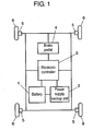
- Fig. 1 shows a structure of a power supply device for vehicles in accordance with this exemplary embodiment of the present invention.
- 12V-battery 1 supplies power into the vehicle
- backup power supply unit 2 is prepared as an auxiliary power supply to battery 1.
- Electronic controller 3 outputs information for controlling a brake of the vehicle.
- Both of battery 1 and backup unit 2 supply power to electronic controller 3.
- Brake pedal 4 conveys the information for controlling the brake of the vehicle to electronic controller 3.
- controller 3 controls brake 5, which applies a brake to tires 6.
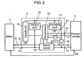
- Fig. 2 shows a circuit diagram of the power supply device for vehicles.
- battery 1 is coupled to ignition generator (IG) terminal 9 disposed on backup unit 2 via ignition switch 8.
- Battery 1 is also coupled to +BC terminal 10 disposed on backup unit 2.
- the +BC terminal 10 is used for supplying power to backup unit 2, and ignition switch 8 is used for starting or ending the operation of the vehicle.
- Battery 1 is coupled to power supply terminal 20 which supplies power to electronic controller 3.
- Backup unit 2 is coupled to electronic controller 3 via communication input terminal 11, communication output terminal 12 and OUT terminal 13.
- Input terminal 11 is used for inputting a signal from controller 3 to backup unit 2.
- Output terminal 12 is used for outputting a signal from backup unit 2 to controller 3.
- OUT terminal 13 is used for outputting a voltage detected by a backup detector 18 disposed in backup unit 2, or for outputting electric charges stored in backup unit 2 when battery 1 encounters an abnormality.
- Backup unit 2 is an auxiliary power supply for supplying power to brake 5 via electronic controller 3 when battery 1 operates abnormally.
- Backup unit 2 includes capacitor unit 15 which is formed of plural capacitors, e.g. plural electrical double-layer capacitors quickly chargeable.
- Backup unit 2 includes charging circuit 16 for charging the capacitor unit 15, and discharging circuit 17 for discharging. Those efforts discussed above are controlled based on an instruction from microprocessor 14.
- Power supply backup unit 2 further includes backup detector 18 which detects a voltage applied by battery 1.
- Backup unit 2 also includes power supply section 19 which allows capacitor unit 15 to discharge to electronic controller 3 via OUT terminal 13 when backup detector 18 detects an abnormal voltage.
- Backup unit 2 includes compulsory operating section 21 which temporarily operates power supply section 19, even battery 1 works normally, according to the instruction from microprocessor 14 in order to monitor the operating status of power supply section 19 that is basically turned off when battery 1 works normally.
- Backup unit 2 also includes output detector 22 which detects an output from power supply section 19 and informs microprocessor 14 of the detection.
- the voltage applied by battery 1 via +BC terminal 10 is detected by a sensor disposed in backup detector 18, and the voltage is supplied to OUT terminal 13. If this voltage applied by battery 1 is not lower than a reference value (9.5V), battery 1 keeps on supplying power to electronic controller 3 after confirming that battery 1 outputs a normal voltage and backup unit 2 works normally.
- a reference value 9V
- the foregoing mechanism allows the vehicle to work properly.
- electronic controller 3 receives information from pedal 4, and based on the information, controller 3 supplies information for controlling the brake of the vehicle to brake 5, which then works according to the information supplied, thereby positively applying a brake to tires 6.
- the vehicle can be controlled with reliability.
- microprocessor 14 transmits a signal, which instructs a discharge of electric charges stored in capacitor unit 15, to discharging circuit 17. Based on the signal, circuit 17 discharges the electric charges stored in capacitor unit 15.
- Backup detector 18 detects a voltage applied to backup unit 2 by battery 1. Power supply backup unit 2 outputs the detected voltage from OUT terminal 13, so that battery 1 supplies power to electronic controller 3. Backup detector 18 includes a sensor for detecting an abnormality of battery 1. When the sensor detects a voltage lower than a reference value (9.5V), detector 18 can detect that battery 1 outputs an abnormal voltage.
- power supply section 19 which stays basically turned-off during a normal operation of battery 1, is turned on. Capacitor unit 15 is thus ready to discharge to OUT terminal 13, and battery 1 stops supplying power. Backup detector 18 outputs a signal corresponding to the stop of supplying the power from battery 1 to microprocessor 14, which then instructs discharging circuit 17 to discharge electric charges stored in capacitor unit 15. This instruction allows supplying the electric charges stored in capacitor unit 15 to electronic controller 3 via power supply section 19 and OUT terminal 13. Meanwhile when battery 1 encounters an abnormality, monitoring the operation of power supply section 19 is not carried out.
- the information of abnormality is transmitted from microprocessor 14 to electronic controller 3 via communication output terminal 12, so that a display unit in the vehicle can indicates that battery 1 operates abnormally.
- the display instructs the driver to stop immediately the vehicle.
- the driver can operate brake 5 via controller 3 by depressing brake pedal 4. As a result, the vehicle can be stopped safely.
- microprocessor 14 transmits a signal for monitoring the operation, then via compulsory operating section 21 forcibly starts power supply section 19 to operate for monitoring the status. It is desirable for power supply section 19 to operate as short as possible for minimizing the consumption of electric charges stored in capacitor unit 15. For this reason, power supply section 19 desirably employs elements having a fast switching speed, such as a field-effect transistor (FET).
- FET field-effect transistor
- Power supply section 19 starts operating and when its output becomes stable, e.g. in 18 milliseconds after starting the operation, output detector 22 detects an output voltage or an output current from capacitor unit 15. Detector 22 transmits the information about the operating status to microprocessor 14 for monitoring based on the information detected whether or not power supply section 19 operates normally.
- the output voltage or output current detected by detector 22 is compared with a given reference voltage or a given reference current. Based on the comparison, whether or not the output voltage or output current has been accurately detected is monitored, so that it is determined whether or not power supply section 19 is defective.
- output detector 22 detects an output voltage or an output current from capacitor unit 15; however, detector 22 can detect both of the voltage and current.
- monitoring the operation of power supply section 19 is halted. Even if battery 1 operates normally, when the voltage of battery 1 is not higher than the voltage of capacitor unit 15, monitoring the operation of power supply section 19, namely, a determination about defective of power supply section 19, is halted in order to prevent the electric charges from flowing to battery 1.
- monitoring the operation of power supply section 19, namely, monitoring of defective can be halted.
- an auxiliary power supply is prepared for powering electronic controller 3 of a vehicle.
- the auxiliary power supply comprises capacitor unit 15, and monitors an operation of power supply section 19 even when battery 1 operates normally for making sure that power supply section 19 can operate normally.
- Those preparations allow monitoring the availability of power supply from capacitor unit 15, and if battery 1 operates abnormally, backup detector 18 detects this abnormality, so that capacitor unit 15 powers electronic controller 3. The reliability of the backup unit to the power supply is thus increased, and as a result, a power supply device for vehicles with improved safety is thus obtainable.
- electronic controller 3 receives information supplied from brake pedal 4, and based on the information, controller 3 outputs information to brake 5 about controlling the brake of the vehicle.
- controller 3 can receive the information in response to the driving status of the vehicle, or receive both of the information supplied from the brake pedal and in response to the driving status of the vehicle.
- an auxiliary power supply is prepared for powering an electronic controller of a vehicle. Because the auxiliary power supply comprises capacitor unit 15, when the battery (main power supply) encounters an abnormality, the auxiliary power supply positively powers the electronic controller. Ensuring the operation of a power supply section around the clock results in obtaining a power supply backup unit with higher reliability, and as a result, a power supply device for vehicles with improved safety is obtainable.
- a power supply device for vehicles includes a power supply backup unit as an auxiliary power supply comprising a capacitor unit formed of plural capacitors.
- the auxiliary power supply includes a power supply section which allows the capacitor unit to power an electronic controller, and a compulsory operating section for operating the power supply section. An operation status of the power supply section is monitored even when the battery operates normally, so that the power supply device for vehicles with higher reliability and improved safety is obtainable.
- This power supply device is used for applying a brake to a vehicle by electrical control, so that this power supply device can be mounted to, e.g. hybrid cars or electric vehicles.
Landscapes
- Engineering & Computer Science (AREA)
- Power Engineering (AREA)
- Mechanical Engineering (AREA)
- Transportation (AREA)
- Business, Economics & Management (AREA)
- Combustion & Propulsion (AREA)
- Chemical & Material Sciences (AREA)
- Emergency Management (AREA)
- Valves And Accessory Devices For Braking Systems (AREA)
- Stand-By Power Supply Arrangements (AREA)
- Charge And Discharge Circuits For Batteries Or The Like (AREA)
- Electric Propulsion And Braking For Vehicles (AREA)
- Air Bags (AREA)
- Steering Control In Accordance With Driving Conditions (AREA)
Claims (9)
- Stromversorgungsvorrichtung für ein Fahrzeug mit:einem elektronischen Regler (3), um Informationen von einem Bremspedal (4) und/oder bezüglich des Betriebszustands des Fahrzeugs zu empfangen und auf der Grundlage der durch den elektronischen Regler (3) empfangenen Informationen an eine Bremse (5) Informationen über Abbremsen des Fahrzeugs auszugeben;einer Batterie (1) zur Energieversorgung der Bremse (5) über den elektronischen Regler (3); undeiner Hilfsstromversorgung (2) für die Energieversorgung der Bremse (5) über den elektronischen Regler (3), wenn die Batterie (1) eine Anomalie antrifft,dadurch gekennzeichnet, dass die Hilfsstromversorgung (2) eine aus einer Mehrzahl von Kondensatoren gebildete Kondensatoreneinheit (16) umfasst, ferner einen Stromversorgungsabschnitt (19), um eine Energieversorgung des elektronischen Reglers (3) durch die Kondensatoreneinheit (16) zu ermöglichen, wenn die Batterie (1) abnormal oder auch normal arbeitet, sowie einen Zwangsbetriebsabschnitt (21), um den Stromversorgungsabschnitt (19) zu betreiben, wobei der Betriebszustand des Stromversorgungsabschnitts (19) im normalen Betrieb der Batterie (1) überwacht wird.
- Stromversorgungsvorrichtung für ein Fahrzeug, wie in Anspruch (1) definiert und dadurch gekennzeichnet, dass die Überwachung des Betriebszustandes des Stromversorgungsabschnitts (19) unterbrochen wird, wenn entweder die Batterie (1) oder die Hilfsstromversorgung (2) abnormal arbeitet.
- Stromversorgungsvorrichtung für ein Fahrzeug, wie in Anspruch (1) definiert und weiter einen Ausgangsdetektor (22) umfassend, um eine Ausgangsspannung und/oder einen Ausgangsstrom der Kondensatoreneinheit (16) zu erfassen, und dadurch gekennzeichnet, dass der Ausgangsdetektor (22) verwendet wird, um den Betriebszustand des Stromversorgungsabschnitts (19) zu überwachen.
- Stromversorgungsvorrichtung für ein Fahrzeug, wie in Anspruch 3 definiert und dadurch gekennzeichnet, dass der Ausgangsdetektor (22) innerhalb einer gegebenen Zeit nach Betriebsbeginn des Stromversorgungsabschnitts (19) die Ausgangsspannung und/oder den Ausgangsstrom der Kondensatoreneinheit (16) erfasst.
- Stromversorgungsvorrichtung für ein Fahrzeug, wie in Anspruch 3 definiert und dadurch gekennzeichnet, dass ein Defekt des Stromversorgungsabschnitts (19) durch einen Vergleich einer durch den Ausgangsdetektor (22) erfassten Ausgangsspannung mit einer gegebenen Referenzspannung und/oder durch einen Vergleich eines durch den Ausgangsdetektor (22) erfassten Ausgangsstromes mit einem gegebenen Referenzstrom bestimmt wird, nachdem der Stromversorgungsabschnitt (19) während einer gegebenen Zeit betrieben worden ist.
- Stromversorgungsvorrichtung für ein Fahrzeug, wie in Anspruch 5 definiert und dadurch gekennzeichnet, dass die Ermittlung eines Defekts des Stromversorgungsabschnitts (19) in einem bestimmten Zeitintervall ausgeführt wird.
- Stromversorgungsvorrichtung für ein Fahrzeug, wie in Anspruch 5 definiert und dadurch gekennzeichnet, dass Information über die Anomalie dem elektronischen Regler (3) übermittelt wird, wenn die Ermittlung ergeben hat, dass der Stromversorgungsabschnitt (19) abnormal arbeitet.
- Stromversorgungsvorrichtung für ein Fahrzeug, wie in Anspruch 5 definiert und dadurch gekennzeichnet, dass eine Ermittlung, ob der Stromversorgungsabschnitt (19) defekt ist, nicht ausgeführt wird, wenn die Batterie (1) eine normale Spannung ausgibt, aber die Spannung nicht höher als eine Spannung der Kondensatoreneinheit (16) ist.
- Stromversorgungsvorrichtung für ein Fahrzeug, wie in Anspruch 1 definiert und dadurch gekennzeichnet, dass der Stromversorgungsabschnitt (19) aus einem Schalter eines Feldeffekttransistors besteht.
Applications Claiming Priority (3)
| Application Number | Priority Date | Filing Date | Title |
|---|---|---|---|
| JP2003182299 | 2003-06-26 | ||
| JP2003182299A JP4715079B2 (ja) | 2003-06-26 | 2003-06-26 | 車両用電源装置 |
| PCT/JP2004/009286 WO2005000656A1 (ja) | 2003-06-26 | 2004-06-24 | 車両用電源装置 |
Publications (3)
| Publication Number | Publication Date |
|---|---|
| EP1518774A1 EP1518774A1 (de) | 2005-03-30 |
| EP1518774A4 EP1518774A4 (de) | 2007-01-10 |
| EP1518774B1 true EP1518774B1 (de) | 2007-10-24 |
Family
ID=33549550
Family Applications (1)
| Application Number | Title | Priority Date | Filing Date |
|---|---|---|---|
| EP04746755A Expired - Lifetime EP1518774B1 (de) | 2003-06-26 | 2004-06-24 | Einrichtung zur energieversorgung eines fahrzeuges |
Country Status (6)
| Country | Link |
|---|---|
| US (1) | US7498689B2 (de) |
| EP (1) | EP1518774B1 (de) |
| JP (1) | JP4715079B2 (de) |
| CN (1) | CN1697748B (de) |
| DE (1) | DE602004009650T2 (de) |
| WO (1) | WO2005000656A1 (de) |
Cited By (1)
| Publication number | Priority date | Publication date | Assignee | Title |
|---|---|---|---|---|
| CN101552484B (zh) * | 2009-01-12 | 2011-01-05 | 熊代荣 | 电动车反充电转换器 |
Families Citing this family (32)
| Publication number | Priority date | Publication date | Assignee | Title |
|---|---|---|---|---|
| JP4418259B2 (ja) * | 2004-02-27 | 2010-02-17 | 株式会社日立製作所 | 電動ブレーキ装置 |
| JP2007014072A (ja) * | 2005-06-29 | 2007-01-18 | Toyota Motor Corp | 駆動システムの制御装置 |
| US7784882B2 (en) * | 2006-09-26 | 2010-08-31 | The Boeing Company | Power interrupt management for an aircraft electric brake system |
| JP4492666B2 (ja) | 2006-10-24 | 2010-06-30 | トヨタ自動車株式会社 | 車両用制動装置 |
| JP4913567B2 (ja) * | 2006-11-29 | 2012-04-11 | 本田技研工業株式会社 | シフトバイワイヤ方式の自動変速機制御装置 |
| JP5119699B2 (ja) * | 2007-03-20 | 2013-01-16 | トヨタ自動車株式会社 | 車両用電源装置 |
| JP5003608B2 (ja) * | 2008-06-20 | 2012-08-15 | トヨタ自動車株式会社 | 車両用制動装置 |
| DE102008041498A1 (de) * | 2008-08-25 | 2010-03-04 | Robert Bosch Gmbh | Bremsanlage für Kraftfahrzeuge |
| DE102011083286A1 (de) * | 2011-09-23 | 2013-03-28 | Robert Bosch Gmbh | Verfahren und Vorrichtung zum Versorgen eines Fahrzeugsystems eines Fahrzeugs mit Energie nach einem Energieversorgungsausfall im Fahrzeug |
| US10347423B2 (en) | 2014-05-12 | 2019-07-09 | Capacitor Sciences Incorporated | Solid multilayer structure as semiproduct for meta-capacitor |
| WO2015175558A2 (en) | 2014-05-12 | 2015-11-19 | Capacitor Sciences Incorporated | Energy storage device and method of production thereof |
| US10340082B2 (en) | 2015-05-12 | 2019-07-02 | Capacitor Sciences Incorporated | Capacitor and method of production thereof |
| US9238465B1 (en) * | 2014-10-13 | 2016-01-19 | Ford Global Technologies, Llc | Road emergency activation |
| CA2965870C (en) | 2014-11-04 | 2023-01-17 | Capacitor Sciences Incorporated | Energy storage devices and methods of production thereof |
| KR20170118764A (ko) | 2015-02-26 | 2017-10-25 | 캐패시터 사이언시스 인코포레이티드 | 자기-회복 커패시터 및 이들의 생산 방법 |
| KR102285145B1 (ko) | 2015-05-11 | 2021-08-04 | 삼성에스디아이 주식회사 | 전기 이동 수단 및 그 제어 방법 |
| US9932358B2 (en) | 2015-05-21 | 2018-04-03 | Capacitor Science Incorporated | Energy storage molecular material, crystal dielectric layer and capacitor |
| US9941051B2 (en) | 2015-06-26 | 2018-04-10 | Capactor Sciences Incorporated | Coiled capacitor |
| US10026553B2 (en) | 2015-10-21 | 2018-07-17 | Capacitor Sciences Incorporated | Organic compound, crystal dielectric layer and capacitor |
| US10305295B2 (en) | 2016-02-12 | 2019-05-28 | Capacitor Sciences Incorporated | Energy storage cell, capacitive energy storage module, and capacitive energy storage system |
| US10153087B2 (en) | 2016-04-04 | 2018-12-11 | Capacitor Sciences Incorporated | Electro-polarizable compound and capacitor |
| US9978517B2 (en) | 2016-04-04 | 2018-05-22 | Capacitor Sciences Incorporated | Electro-polarizable compound and capacitor |
| US10395841B2 (en) | 2016-12-02 | 2019-08-27 | Capacitor Sciences Incorporated | Multilayered electrode and film energy storage device |
| US11420608B2 (en) * | 2017-03-30 | 2022-08-23 | Panasonic Intellectual Property Management Co., Ltd. | Vehicle electricity storage device |
| JP6861567B2 (ja) | 2017-04-19 | 2021-04-21 | 矢崎総業株式会社 | 車両用回路体 |
| JP7186049B2 (ja) * | 2018-09-28 | 2022-12-08 | 株式会社デンソーテン | 電源監視装置および電源監視方法 |
| JP7108962B2 (ja) * | 2018-12-03 | 2022-07-29 | 株式会社オートネットワーク技術研究所 | 車載用のバックアップ電源制御装置及び車載用のバックアップ電源装置 |
| DE102019112874A1 (de) * | 2019-05-16 | 2020-11-19 | Schaeffler Technologies AG & Co. KG | Gewährleistung eines notfallbetriebs eines aktors |
| US10923946B1 (en) | 2019-10-30 | 2021-02-16 | Bendix Commercial Vehicle Systems Llc | Hybrid backup power supply system |
| EP4015322B1 (de) * | 2020-12-17 | 2023-12-06 | KNORR-BREMSE Systeme für Nutzfahrzeuge GmbH | Sicherungssystem für eine elektronische feststellbremse und verfahren zur bereitstellung von sicherungsleistung |
| US12272539B2 (en) | 2021-01-26 | 2025-04-08 | Panasonic Intellectual Property Management Co., Ltd. | Auxiliary power supply system, module, auxiliary power supply control method, and program |
| CN115465117B (zh) * | 2022-10-17 | 2025-07-15 | 贵州翰凯斯智能技术有限公司 | 车辆制动控制系统、方法及存储介质 |
Family Cites Families (16)
| Publication number | Priority date | Publication date | Assignee | Title |
|---|---|---|---|---|
| JPH01274628A (ja) * | 1988-04-25 | 1989-11-02 | Nippon Denso Co Ltd | 乗員保護装置の異常判定装置 |
| JP2518368B2 (ja) * | 1988-12-27 | 1996-07-24 | いすゞ自動車株式会社 | 車両用電源装置 |
| JP3204326B2 (ja) * | 1991-10-25 | 2001-09-04 | いすゞ自動車株式会社 | 車両用始動装置 |
| US5373226A (en) * | 1991-11-15 | 1994-12-13 | Nec Corporation | Constant voltage circuit formed of FETs and reference voltage generating circuit to be used therefor |
| JP3687409B2 (ja) * | 1999-04-26 | 2005-08-24 | トヨタ自動車株式会社 | 車両用電源供給制御装置 |
| JP3838322B2 (ja) | 1999-10-18 | 2006-10-25 | トヨタ自動車株式会社 | 電気システムおよび車両用ブレーキシステム |
| JP2001197606A (ja) * | 2000-01-06 | 2001-07-19 | Yanmar Diesel Engine Co Ltd | 走行車両用電力供給切換装置 |
| JP3549806B2 (ja) * | 2000-03-01 | 2004-08-04 | 株式会社日立製作所 | 自動車用電源の制御装置 |
| JP2001359244A (ja) * | 2000-06-14 | 2001-12-26 | Shizuki Electric Co Inc | キャパシタによる二次蓄電池アシスト回路 |
| JP3842984B2 (ja) * | 2001-04-06 | 2006-11-08 | 三菱重工業株式会社 | フォークリフトの電源装置 |
| JP3896258B2 (ja) * | 2001-04-25 | 2007-03-22 | 株式会社日立製作所 | 自動車電源装置 |
| JP4396066B2 (ja) * | 2001-08-07 | 2010-01-13 | 株式会社日立製作所 | 電動ブレーキ装置 |
| JP4187085B2 (ja) * | 2001-08-24 | 2008-11-26 | 三菱電機株式会社 | 車両用乗員保護装置 |
| JP3738721B2 (ja) * | 2001-10-02 | 2006-01-25 | 株式会社デンソー | 組電池電圧検出回路 |
| JP3969341B2 (ja) * | 2003-03-03 | 2007-09-05 | 松下電器産業株式会社 | 車両用電源装置 |
| JP2004364361A (ja) * | 2003-06-02 | 2004-12-24 | Auto Network Gijutsu Kenkyusho:Kk | 車載電源装置 |
-
2003
- 2003-06-26 JP JP2003182299A patent/JP4715079B2/ja not_active Expired - Lifetime
-
2004
- 2004-06-24 DE DE200460009650 patent/DE602004009650T2/de not_active Expired - Lifetime
- 2004-06-24 EP EP04746755A patent/EP1518774B1/de not_active Expired - Lifetime
- 2004-06-24 CN CN2004800006619A patent/CN1697748B/zh not_active Expired - Lifetime
- 2004-06-24 WO PCT/JP2004/009286 patent/WO2005000656A1/ja not_active Ceased
- 2004-06-24 US US10/523,556 patent/US7498689B2/en not_active Expired - Lifetime
Cited By (1)
| Publication number | Priority date | Publication date | Assignee | Title |
|---|---|---|---|---|
| CN101552484B (zh) * | 2009-01-12 | 2011-01-05 | 熊代荣 | 电动车反充电转换器 |
Also Published As
| Publication number | Publication date |
|---|---|
| JP2005014754A (ja) | 2005-01-20 |
| EP1518774A4 (de) | 2007-01-10 |
| EP1518774A1 (de) | 2005-03-30 |
| DE602004009650T2 (de) | 2008-08-14 |
| CN1697748A (zh) | 2005-11-16 |
| US20050269170A1 (en) | 2005-12-08 |
| JP4715079B2 (ja) | 2011-07-06 |
| US7498689B2 (en) | 2009-03-03 |
| CN1697748B (zh) | 2010-06-23 |
| DE602004009650D1 (de) | 2007-12-06 |
| WO2005000656A1 (ja) | 2005-01-06 |
Similar Documents
| Publication | Publication Date | Title |
|---|---|---|
| US7498689B2 (en) | Power supply device for vehicle | |
| US11390167B2 (en) | Power supply system | |
| EP1529694B1 (de) | Kraftfahrzeugenergieversorgung | |
| JP3969341B2 (ja) | 車両用電源装置 | |
| EP3561982A1 (de) | Redundantes energieversorgungssystem | |
| US20040178679A1 (en) | Uninterruptible power supply | |
| JP2008072880A (ja) | 電源システム | |
| WO2019116997A1 (ja) | 車載電源装置 | |
| JP2005145097A (ja) | 車両用電源システム | |
| KR20010103998A (ko) | 하이브리드 전기 자동차의 누전 차단장치 및 그 제어방법 | |
| US11769914B2 (en) | Working vehicle | |
| JP4003798B2 (ja) | 車両用電源装置 | |
| CN116923194A (zh) | 电源控制装置、控制方法以及存储介质 | |
| KR20080036228A (ko) | 차량용 보조 전원 장치와 이를 이용한 차량용 전원 장치,자동차 | |
| JP7358424B2 (ja) | 車両電源システム | |
| JP3935117B2 (ja) | バッテリの負荷電力検出装置 | |
| JP2005045913A (ja) | 車両用電源装置 | |
| CN100482498C (zh) | 应急电源装置 | |
| CN109643907A (zh) | 蓄电部控制装置 | |
| JP7783795B2 (ja) | 車両電源システム | |
| KR100256907B1 (ko) | 차량의 전기 전자 제어장치 | |
| CN117734615A (zh) | 车辆电源系统 | |
| KR20170091897A (ko) | 배터리 상태 표시 시스템 및 방법 |
Legal Events
| Date | Code | Title | Description |
|---|---|---|---|
| PUAI | Public reference made under article 153(3) epc to a published international application that has entered the european phase |
Free format text: ORIGINAL CODE: 0009012 |
|
| 17P | Request for examination filed |
Effective date: 20050119 |
|
| AK | Designated contracting states |
Kind code of ref document: A1 Designated state(s): AT BE BG CH CY CZ DE DK EE ES FI FR GB GR HU IE IT LI LU MC NL PL PT RO SE SI SK TR |
|
| AX | Request for extension of the european patent |
Extension state: AL HR LT LV MK |
|
| RIC1 | Information provided on ipc code assigned before grant |
Ipc: B60T 17/18 20060101AFI20060127BHEP Ipc: H02J 9/06 20060101ALI20060127BHEP Ipc: B60R 16/02 20060101ALI20060127BHEP |
|
| DAX | Request for extension of the european patent (deleted) | ||
| RBV | Designated contracting states (corrected) |
Designated state(s): DE FR GB |
|
| A4 | Supplementary search report drawn up and despatched |
Effective date: 20061213 |
|
| RIC1 | Information provided on ipc code assigned before grant |
Ipc: B60T 17/22 20060101ALI20061207BHEP Ipc: H02J 1/10 20060101ALI20061207BHEP Ipc: B60T 17/18 20060101AFI20060127BHEP Ipc: B60R 16/02 20060101ALI20061207BHEP Ipc: H02J 9/06 20060101ALI20061207BHEP Ipc: B60R 16/04 20060101ALI20061207BHEP |
|
| 17Q | First examination report despatched |
Effective date: 20070205 |
|
| GRAP | Despatch of communication of intention to grant a patent |
Free format text: ORIGINAL CODE: EPIDOSNIGR1 |
|
| GRAS | Grant fee paid |
Free format text: ORIGINAL CODE: EPIDOSNIGR3 |
|
| GRAA | (expected) grant |
Free format text: ORIGINAL CODE: 0009210 |
|
| AK | Designated contracting states |
Kind code of ref document: B1 Designated state(s): DE FR GB |
|
| REG | Reference to a national code |
Ref country code: GB Ref legal event code: FG4D |
|
| REF | Corresponds to: |
Ref document number: 602004009650 Country of ref document: DE Date of ref document: 20071206 Kind code of ref document: P |
|
| ET | Fr: translation filed | ||
| PLBE | No opposition filed within time limit |
Free format text: ORIGINAL CODE: 0009261 |
|
| STAA | Information on the status of an ep patent application or granted ep patent |
Free format text: STATUS: NO OPPOSITION FILED WITHIN TIME LIMIT |
|
| 26N | No opposition filed |
Effective date: 20080725 |
|
| REG | Reference to a national code |
Ref country code: GB Ref legal event code: 746 Effective date: 20091221 |
|
| PGFP | Annual fee paid to national office [announced via postgrant information from national office to epo] |
Ref country code: GB Payment date: 20140618 Year of fee payment: 11 |
|
| PGFP | Annual fee paid to national office [announced via postgrant information from national office to epo] |
Ref country code: DE Payment date: 20140618 Year of fee payment: 11 |
|
| PGFP | Annual fee paid to national office [announced via postgrant information from national office to epo] |
Ref country code: FR Payment date: 20140609 Year of fee payment: 11 |
|
| REG | Reference to a national code |
Ref country code: DE Ref legal event code: R119 Ref document number: 602004009650 Country of ref document: DE |
|
| GBPC | Gb: european patent ceased through non-payment of renewal fee |
Effective date: 20150624 |
|
| REG | Reference to a national code |
Ref country code: FR Ref legal event code: ST Effective date: 20160229 |
|
| PG25 | Lapsed in a contracting state [announced via postgrant information from national office to epo] |
Ref country code: DE Free format text: LAPSE BECAUSE OF NON-PAYMENT OF DUE FEES Effective date: 20160101 Ref country code: GB Free format text: LAPSE BECAUSE OF NON-PAYMENT OF DUE FEES Effective date: 20150624 |
|
| PG25 | Lapsed in a contracting state [announced via postgrant information from national office to epo] |
Ref country code: FR Free format text: LAPSE BECAUSE OF NON-PAYMENT OF DUE FEES Effective date: 20150630 |