EP1518682A1 - Tintenstrahldruckkopf und dazugehöriges Überprüfungsverfahren - Google Patents
Tintenstrahldruckkopf und dazugehöriges Überprüfungsverfahren Download PDFInfo
- Publication number
- EP1518682A1 EP1518682A1 EP04022227A EP04022227A EP1518682A1 EP 1518682 A1 EP1518682 A1 EP 1518682A1 EP 04022227 A EP04022227 A EP 04022227A EP 04022227 A EP04022227 A EP 04022227A EP 1518682 A1 EP1518682 A1 EP 1518682A1
- Authority
- EP
- European Patent Office
- Prior art keywords
- ink
- pressure chambers
- arrays
- printer head
- jet printer
- Prior art date
- Legal status (The legal status is an assumption and is not a legal conclusion. Google has not performed a legal analysis and makes no representation as to the accuracy of the status listed.)
- Granted
Links
- 238000000034 method Methods 0.000 title claims description 17
- 238000003491 array Methods 0.000 claims abstract description 83
- 238000007689 inspection Methods 0.000 claims abstract description 34
- 239000000976 ink Substances 0.000 claims description 196
- 239000012530 fluid Substances 0.000 claims description 27
- 125000006850 spacer group Chemical group 0.000 description 23
- 230000007547 defect Effects 0.000 description 15
- 238000004891 communication Methods 0.000 description 8
- 239000000853 adhesive Substances 0.000 description 7
- 230000001070 adhesive effect Effects 0.000 description 7
- 230000002950 deficient Effects 0.000 description 6
- 238000007639 printing Methods 0.000 description 4
- 238000002955 isolation Methods 0.000 description 3
- 238000003754 machining Methods 0.000 description 3
- 230000002093 peripheral effect Effects 0.000 description 2
- 229920003002 synthetic resin Polymers 0.000 description 2
- 239000000057 synthetic resin Substances 0.000 description 2
- 229910000990 Ni alloy Inorganic materials 0.000 description 1
- 229910000831 Steel Inorganic materials 0.000 description 1
- 230000002411 adverse Effects 0.000 description 1
- 238000007796 conventional method Methods 0.000 description 1
- 238000013016 damping Methods 0.000 description 1
- 230000003247 decreasing effect Effects 0.000 description 1
- 230000000694 effects Effects 0.000 description 1
- 238000005530 etching Methods 0.000 description 1
- 239000007789 gas Substances 0.000 description 1
- 239000011261 inert gas Substances 0.000 description 1
- 239000007788 liquid Substances 0.000 description 1
- 239000000463 material Substances 0.000 description 1
- 239000002184 metal Substances 0.000 description 1
- 229910052751 metal Inorganic materials 0.000 description 1
- 239000000203 mixture Substances 0.000 description 1
- 230000001902 propagating effect Effects 0.000 description 1
- 239000010959 steel Substances 0.000 description 1
- XLYOFNOQVPJJNP-UHFFFAOYSA-N water Substances O XLYOFNOQVPJJNP-UHFFFAOYSA-N 0.000 description 1
Images


Classifications
-
- B—PERFORMING OPERATIONS; TRANSPORTING
- B41—PRINTING; LINING MACHINES; TYPEWRITERS; STAMPS
- B41J—TYPEWRITERS; SELECTIVE PRINTING MECHANISMS, i.e. MECHANISMS PRINTING OTHERWISE THAN FROM A FORME; CORRECTION OF TYPOGRAPHICAL ERRORS
- B41J2/00—Typewriters or selective printing mechanisms characterised by the printing or marking process for which they are designed
- B41J2/005—Typewriters or selective printing mechanisms characterised by the printing or marking process for which they are designed characterised by bringing liquid or particles selectively into contact with a printing material
- B41J2/01—Ink jet
- B41J2/135—Nozzles
- B41J2/14—Structure thereof only for on-demand ink jet heads
- B41J2/14201—Structure of print heads with piezoelectric elements
- B41J2/14209—Structure of print heads with piezoelectric elements of finger type, chamber walls consisting integrally of piezoelectric material
-
- B—PERFORMING OPERATIONS; TRANSPORTING
- B41—PRINTING; LINING MACHINES; TYPEWRITERS; STAMPS
- B41J—TYPEWRITERS; SELECTIVE PRINTING MECHANISMS, i.e. MECHANISMS PRINTING OTHERWISE THAN FROM A FORME; CORRECTION OF TYPOGRAPHICAL ERRORS
- B41J2/00—Typewriters or selective printing mechanisms characterised by the printing or marking process for which they are designed
- B41J2/005—Typewriters or selective printing mechanisms characterised by the printing or marking process for which they are designed characterised by bringing liquid or particles selectively into contact with a printing material
- B41J2/01—Ink jet
- B41J2/135—Nozzles
- B41J2/14—Structure thereof only for on-demand ink jet heads
- B41J2/14201—Structure of print heads with piezoelectric elements
- B41J2/14209—Structure of print heads with piezoelectric elements of finger type, chamber walls consisting integrally of piezoelectric material
- B41J2002/14225—Finger type piezoelectric element on only one side of the chamber
-
- B—PERFORMING OPERATIONS; TRANSPORTING
- B41—PRINTING; LINING MACHINES; TYPEWRITERS; STAMPS
- B41J—TYPEWRITERS; SELECTIVE PRINTING MECHANISMS, i.e. MECHANISMS PRINTING OTHERWISE THAN FROM A FORME; CORRECTION OF TYPOGRAPHICAL ERRORS
- B41J2/00—Typewriters or selective printing mechanisms characterised by the printing or marking process for which they are designed
- B41J2/005—Typewriters or selective printing mechanisms characterised by the printing or marking process for which they are designed characterised by bringing liquid or particles selectively into contact with a printing material
- B41J2/01—Ink jet
- B41J2/135—Nozzles
- B41J2/14—Structure thereof only for on-demand ink jet heads
- B41J2/14201—Structure of print heads with piezoelectric elements
- B41J2002/14306—Flow passage between manifold and chamber
-
- B—PERFORMING OPERATIONS; TRANSPORTING
- B41—PRINTING; LINING MACHINES; TYPEWRITERS; STAMPS
- B41J—TYPEWRITERS; SELECTIVE PRINTING MECHANISMS, i.e. MECHANISMS PRINTING OTHERWISE THAN FROM A FORME; CORRECTION OF TYPOGRAPHICAL ERRORS
- B41J2/00—Typewriters or selective printing mechanisms characterised by the printing or marking process for which they are designed
- B41J2/005—Typewriters or selective printing mechanisms characterised by the printing or marking process for which they are designed characterised by bringing liquid or particles selectively into contact with a printing material
- B41J2/01—Ink jet
- B41J2/135—Nozzles
- B41J2/14—Structure thereof only for on-demand ink jet heads
- B41J2002/14419—Manifold
Definitions
- the present invention relates to an ink jet printer head having a plurality of pressure chambers arranged in a plurality of arrays, and to a method of inspecting the ink jet printer head about whether the arrays of pressure chambers are fluid-tightly isolated from each other.
- Japanese Patent Application Publication No. 2001-260349 or its corresponding U.S. Patent No. 6,604,817 discloses a conventional piezoelectric ink jet printer head including a channel unit constituted by a plurality of sheet members which are stacked on each other via adhesive; a piezoelectric actuator which is bonded to a back surface of the channel unit; and a flexible flat cable which is stacked on, and bonded to, a back surface of the piezoelectric actuator, for electrically connecting the actuator to an external device.
- the above-indicated channel unit includes a nozzle sheet having a plurality of ink ejection nozzles opening in a front surface of the printer head; a base sheet having a plurality of pressure chambers communicating with the ink ejection nozzles, respectively; and a manifold sheet and another or other sheet members having a common ink chamber (i.e., a manifold chamber) connected to an ink supply source, and a plurality of ink channels connected to the pressure chambers, respectively.
- the nozzle sheet, the base sheet, the manifold sheet and the other sheet members are stacked on, and adhered to, each other.
- this printer head when an active portion of the piezoelectric actuator that corresponds to an arbitrary one of the pressure chambers of the channel unit is deformed in a direction parallel to the direction of stacking of the sheet members, a droplet of ink is ejected from the arbitrary pressure chamber via the corresponding ink ejection nozzle, so that a desired image is printed or recorded on a recording medium such as a sheet of paper.
- FIG. 6 shows an upper surface of a base sheet 117 of a channel unit of the conventional ink jet printer head.
- the base sheet 117 has a plurality of pressure chambers 136 which are formed through a thickness of the sheet 117 such that the pressure chambers 136 are arranged in a plurality of arrays (only three arrays are shown) corresponding to a plurality of arrays in which a plurality of ink ejection nozzles 104 are arranged.
- the base sheet 117 additionally has a plurality of ink supply holes 160 (160a, 160b, 160c, ...) formed through the thickness thereof.
- the channel unit has a plurality of common ink chambers (i.e., manifold chambers) 107 which are elongate in a lengthwise direction of the channel unit and are connected to the ink supply holes 160, respectively; a plurality of communication holes 138 arranged in a plurality of arrays; and a plurality of through-holes 137 arranged in a plurality of arrays.
- the arrays of pressure chambers 136 extend along the common ink chambers 107, respectively, in the lengthwise direction of the channel unit.
- a plurality of kinds of color inks are supplied to the common ink chambers 107, respectively, via the respective ink supply holes 160, and then each of the color inks is delivered from a corresponding one of the common ink chambers 107 to respective one end portions of the pressure chambers 136 if a corresponding one of the arrays via the respective communication holes 138.
- the ink accommodated by an arbitrary one of the pressure chambers 136 is pressurized by a corresponding active portion of a piezoelectric actuator, not shown, a droplet of the ink is ejected from a corresponding one of the ink ejection nozzles 104 via the other end portion of the arbitrary pressure chamber 136 and a corresponding one of the through-holes 137.
- two closure sheet members are respectively adhered to two opposite planar surfaces of the base sheet 117 having the pressure chambers 136, so that the pressure chambers 136 are fluid-tightly closed by those closure sheet members and are thereby isolated from each other.
- Those two closure sheet members are a sheet member of the channel unit that is adhered to a lower planar surface of the base sheet 117, and a lowermost sheet member of the piezoelectric actuator that is adhered to an upper planar surface of the base sheet 117.
- two or more pressure chambers 136 may communicate with each other.
- ink may leak from the one pressure chamber 136 to a location outside the printer head, or to one or two adjacent pressure chambers 136 located adjacent the one pressure chamber 136.
- a process of producing the ink jet printer head employs a step of inspecting whether the sheet members of the channel unit and/or the piezoelectric actuator have been appropriately stacked on, and adhered to, each other such that the pressure chambers 136 are fluid-tightly isolated from each other.
- the ink may leak in a first route, indicated by "A”, from the pressure chamber 136c to an outer peripheral edge of the base sheet 117 (i.e., a location outside the printer head); in a second route, indicated by “B”, from the pressure chamber 136c to an adjacent pressure chamber 136d located adjacent the pressure chamber 136c in a same array; or in a third route, indicated by "C”, from the pressure chamber 136c to an adjacent pressure chamber 136e located adjacent the pressure chamber 136c, in an array located adjacent the array in which the pressure chamber 136c is arranged.
- A first route
- B from the pressure chamber 136c to an adjacent pressure chamber 136d located adjacent the pressure chamber 136c in a same array
- C third route
- the leakage of ink via the route "A" can be effectively prevented because a considerably large adhesion area can be provided between each pressure chamber 136 and the outer peripheral edge of the base sheet 117 and additionally one or more adhesive pouring grooves and/or one or more adhesive relieving grooves can be formed in the adhesion area.
- the leakage of ink via the route "B” does not adversely influence the quality of printing so much, because a pitch of arrangement of the pressure chambers 136 in a same array is very small and additionally a same kind of ink is accommodated by those pressure chambers 136.
- the leakage of ink via the route "C" may cause a problem of mixture of different kinds of color inks, because a distance between two adjacent arrays of pressure chambers 136 is considerably large and the different kinds of color inks are accommodated by the different arrays of pressure chambers 136, respectively.
- the above-indicated step of inspecting the fluid-tight isolation of the pressure chambers 136 is arranged such that after the piezoelectric actuator is bonded to the upper surface of the channel unit (hereinafter, this will be referred to as the bonded body), all the ink ejection nozzles 104 are temporarily fluid-tightly closed, and a pressurized air is supplied to each one of the ink supply holes 160. If air leaks from any of the pressure chambers 136 of, e.g., the first array 161a that communicate with the first ink supply hole 160a via the corresponding common ink chamber 107, then the pressure of the pressurized air will lower.
- the fluid-tight isolation of the pressure chambers 136 can be inspected by measuring the pressure of the pressurized air after a prescribed time period has elapsed. If the leakage of the pressurized air is detected, i.e., the isolation of the pressure chambers 136 is found defective, then the bonded body is discarded and is not conveyed to any subsequent steps.
- the pressure chambers 136 are arranged in the plurality of arrays 161a, 161b, 161c, so as to correspond to the plurality of arrays in which the ink ejection nozzles 104 are arranged. If the pressurized air is simultaneously charged into, e.g., the two ink supply holes 160a, 160b corresponding to the first and second arrays 161a, 161b of pressure chambers 136, the pressurized air is supplied to those pressure chambers 136 via the corresponding common ink chambers 107.
- a time needed to perform the inspection cannot be shortened by charging the pressurized air simultaneously into all the ink supply holes 160, or two or more adjacent ink supply holes 160, because a defect of the adhesion of the area W between each pair of adjacent arrays 161 of pressure chambers 136, that is, leakage of air through the area W cannot be found by this inspection.
- each one array 161 of pressure chambers 136 by charging the pressurized air into only the corresponding ink supply hole 160, or inspect each group of arrays 161 of pressure chambers 136 (e.g., the first and third arrays 161a, 161c of pressure chambers 136) that are not located adjacent each other, by charging the pressurized air into the corresponding ink supply holes 160 (e.g., the ink supply holes 160a, 160c).
- this inspecting step is cumbersome and time-consuming.
- Fig. 7 shows one ink supply hole 160d that communicates with two common ink chambers 107, 107 corresponding to two adjacent arrays 161d, 161e of pressure chambers 136, so that a same kind of ink is supplied from the ink supply hole 160d to each of the pressure chambers 136 of the two arrays 161d, 161e.
- the pressurized air is simultaneously charged into the two arrays 161d, 161e of pressure chambers 136 and, even if air may leak through the area W between the two arrays 161d, 161e of pressure chambers, the pressure of the pressurized air charged into the pressure chambers 136 does not lower.
- the defect of the area W cannot be found from the bonded body of the channel unit and the piezoelectric actuator.
- an ink jet printer head comprising a channel unit having a plurality of ink ejection nozzles arranged in a plurality of arrays and opening in a front surface of the ink jet printer head, a plurality of pressure chambers arranged in a plurality of arrays and communicating with the ink ejection nozzles, respectively, and a plurality of ink channels which deliver at least one kind of ink from at least one ink inlet to the pressure chambers, respectively, and then deliver the at least one kind of ink from the pressure chambers to the ink ejection nozzles, respectively.
- the channel unit includes a first sheet member having a first planar surface in which a plurality of arrays of recesses defining the plurality of arrays of pressure chambers, respectively, open.
- the printer head further comprises a second sheet member having a second planar surface which is adhered to the first planar surface of the first sheet member so as to close the recesses opening in the first planar surface.
- At least one of the first sheet member and the second sheet member has at least one inspection-related groove which is located between at least one pair of arrays of recesses of the plurality of arrays of recesses, extends along the at least one pair of arrays of recesses, and communicates with an outside space.
- the ink jet printer head in accordance with the first aspect of the present invention may have a defect of the adhesion of the first and second sheet members and accordingly have a route in which a fluid leaks between two pressure chambers respectively belonging to the different arrays.
- a fluid is charged into the ink channels and the pressure chambers via the ink inlet in a state in which the ink ejection nozzles are fluid-tightly closed
- the fluid leaking from at least one of the two pressure chambers reaches the inspection-related groove located between the different arrays of pressure chambers, and eventually flows out of the inspection-related groove into the outside space.
- the defect of fluid-tightness of the pressure chambers unit can be easily detected.
- a method of inspecting an ink jet printer head comprising the steps of temporarily closing the ink ejection nozzles, charging a fluid into the ink channels and the pressure chambers via said at least one ink inlet, and inspecting whether the fluid leaks from the ink jet printer head to the outside space.
- the printer head inspecting method in accordance with the second aspect of the present invention if the printer head has a defect of the adhesion of the first and second sheet members and accordingly has a route in which a fluid leaks between two pressure chambers respectively belonging to the different arrays, the fluid leaking from at least one of the two pressure chambers reaches the inspection-related groove located between the different arrays of pressure chambers, and eventually flows out of the inspection-related groove into the outside space.
- the defect of fluid-tightness of the pressure chambers can be easily detected.
- the bonded body When a defect of a bonded body in which the channel unit and an actuator (e.g., a piezoelectric actuator) are bonded to each other is detected, the bonded body can be discarded before it is conveyed to one or more subsequent steps. Thus, the yield of the printer heads as final products can be largely improved.
- an actuator e.g., a piezoelectric actuator
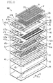
- a piezoelectric ink jet printer head 100 as an embodiment of the present invention includes a channel unit 1 which is constituted by a plurality of sheet members; a sheet-type piezoelectric actuator 2 which is bonded to the channel unit 1; and a flexible flat cable 3 (Fig. 3A) which is stacked on, and bonded with adhesive, to an upper surface of the piezoelectric actuator 2, for the purpose of electrically connecting the actuator 2 to an external device, not shown:
- the channel unit 1 as the lowermost layer of the printer head 100 has a plurality of ink ejection nozzles 4 which open in a lower (i.e., a front) surface of the head 100 and each of which ejects a droplet of ink in a downward direction.
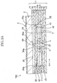
- the channel unit 1 is constructed as shown in Figs. 1, 2, and 3A. More specifically described, the channel unit 1 is constituted by eight thin sheet members which are stacked on, and bonded with adhesive to, each other.
- the eight sheet members include a nozzle sheet 11, a first spacer sheet 12, a damper sheet 13, two manifold sheets 14a, 14b, a second spacer sheet 15, a third spacer sheet 16, and a base sheet 17.
- the base sheet 17 provides a first sheet member; and the third spacer sheet 16 provides a second sheet member.
- each of the seven sheet members 12, 13, 14a 14b and 15 through 17, except for the nozzle sheet 11, is formed of a 42% nickel alloy steel sheet, and has a thickness of from about 50 ⁇ m to about 150 ⁇ m.
- the nozzle sheet 11 is formed of a synthetic resin, and has a plurality of ink ejection nozzles 4 each of which has a small diameter (e.g., 25 ⁇ m) and which are formed through a thickness of the sheet 11, at a small regular interval. More specifically described, the ink ejection nozzles 4 are arranged in five arrays in a first direction (i.e., a lengthwise direction or an X direction) of the channel unit 1 or the printer head 100.
- a first direction i.e., a lengthwise direction or an X direction
- the base sheet 17 has a plurality of pressure chambers 36 which are arranged in five arrays in the lengthwise direction (i.e., the X direction) of the channel unit 1.
- each of the pressure chambers 36 has an outlet end 36a communicating with a corresponding one of the ink ejection nozzles 4, and an inlet end 36b communicating with a corresponding one of five common ink chambers 7, described later, and is elongate in a lengthwise direction thereof passing through the outlet and inlet ends 36a, 36b thereof.
- a plurality of recesses defining the pressure chambers 36 are formed through a thickness of the base sheet 17, such that the lengthwise direction of each recess or each pressure chamber 36 is parallel to a widthwise direction or a Y direction of the channel unit 11 or the printer head 100, and each recess or each pressure chamber 36 has a small width in the X direction perpendicular to the Y direction.
- each of the six sheet members 16, 15, 14b, 14a, 13, 12 has the small-diameter through-holes 37 arranged in five arrays in the X direction.
- the third spacer sheet 16 underlying the base sheet 17 has a plurality of communication holes 38 as respective portions of the ink channels that communicate with the respective inlet ends 36b of the pressure chambers 36 of the base sheet 17.
- the communication holes 38 are formed through a thickness of the third spacer sheet 16, at respective positions aligned with the respective inlet ends 36b of the pressure chambers 36.
- the second spacer sheet 15 underlying the third spacer sheet 16 has a plurality of connection passages 40 each of which connects between a corresponding one of the common ink chambers 7, described later, and a corresponding one of the pressure chambers 36, so that ink is supplied from the one common ink chamber 7 to the one pressure chamber 36.
- Each of the connection passages 40 includes an inlet portion for receiving the ink from the corresponding common ink chamber 7; an outlet portion communicating with the corresponding pressure chamber 36 via the corresponding communication hole 38; and a restrictor portion which is located between the inlet and outlet portions and has a cross-section area smaller than that of each of the inlet and outlet portions so as to exhibit the greater flow resistance than that of any other portion of the each connection passage 40.
- the two manifold sheets 14a, 14b cooperate with each other to have the five common ink chambers 7 which extend in the lengthwise or X direction of the channel unit 1, along the five arrays of ink ejection nozzles 4, respectively.
- Each of the five common ink chambers 7 is formed through respective thickness of the two manifold sheets 14a, 14b.
- the two manifold sheets 14a, 14b are stacked on each other, an upper surface of the upper manifold sheet 14b is fluid-tightly covered with the second spacer sheet 15, and a lower surface of the lower manifold sheet 14a is fluid-tightly covered with the damper sheet 13.
- the five fluid-tight common ink chambers (i.e., five liquid-tight manifold chambers) 7 are defined.
- Each of the five common ink chambers 7 partly overlaps, in its plan view, the pressure chambers 36 of a corresponding one of the five arrays, and extends along the corresponding array of pressure chambers 36.
- the damper sheet 13 underlying the lower manifold sheet 14a has, in a lower surface thereof, five damper chambers 45 which are isolated from the corresponding common ink chambers 7.
- the damper chambers 45 do not extend through a thickness of the damper sheet 13, and open in only the lower surface of the same 13.
- the damper chambers 45 have respective shapes identical with those of the corresponding common ink chambers 7, and are aligned with the corresponding common ink chambers 7. Since the damper sheet 13 is formed of a metal sheet that is elastically deformable by an appropriate amount, respective diaphragm portions of the damper sheet 13 that define the five damper chambers 45 can vibrate between the corresponding common ink chambers 7 and the corresponding damper chambers 45.
- each of the base sheet 17, the third spacer sheet 16, and the second spacer sheet 15 has, in one of lengthwise opposite end portions thereof, four ink supply holes 47 (47a, 47b, 47c, 47d) which are formed through a thickness thereof.
- the respective ink supply holes 47a of the three sheet members 17, 16, 15 are vertically aligned with each other; and likewise the respective ink supply holes 47b, the respective ink supply holes 47c, and the respective ink supply holes 47d, of the three sheet members 17, 16, 15 are vertically aligned with each other.
- four color inks supplied from four ink tanks, not shown, that are located outside the ink jet printer head 100 are delivered to respective one end portions of the five common ink chambers 7 via the four ink supply holes 47.
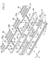
- the ink supply holes 47 communicate with the ink ejection nozzles 4 via the respective ink channels. More specifically described, each of the four color inks is supplied from a corresponding one of the four ink supply holes 47 to a corresponding one of the five common ink chambers 7 (or corresponding two common ink chambers 7) and, then, as shown in Fig. 2, the each color ink is delivered from the corresponding one or two common ink chamber or chambers 7 to the inlet portion 36b of each of the pressure chambers 36 of a corresponding one of the five arrays (or corresponding two arrays) via the corresponding connection passage 40 of the second spacer sheet 15 and the corresponding communication hole 38 of the third spacer sheet 16.
- the piezoelectric actuator 36 When the piezoelectric actuator 36 is driven or operated in a manner described later, the four color inks are delivered from the five arrays of pressure chambers 36 to the five arrays of ink ejection nozzles 4 via the five arrays of through-holes 37 of each of the six sheet members 16, 15, 14b, 14a, 13, 12.
- the channel unit 1 has the four ink inlet holes 47a, 47b, 47c 47d, and the five common ink chambers 7. Only the first ink inlet hole 47a communicates with the two common ink chambers 7 that are located in a left-hand end portion of the manifold sheets 14a, 14b. A black ink is supplied to the first ink inlet hole 47a, because the black ink is more frequently used than the other color inks, i.e., yellow, magenta, and cyan inks that are supplied to the other ink inlet holes 47b, 47c, 47d, respectively.
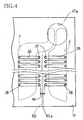
- At least one of the base sheet 17 and the third spacer sheet 16 has a plurality of straight inspection-related grooves 50 each of which is located between a corresponding pair of adjacent arrays of pressure chambers 36, extends along the arrays of pressure chambers 36 in the lengthwise or X direction of the channel unit 1, and communicates with an outside space.
- the inspection-related grooves 50 are formed in the upper planar surface of the third spacer sheet 16 that is adhered to the lower planar surface of the base sheet 17, such that the grooves 50 do not extend through the thickness of the third spacer sheet 16.
- Each of the four inspection-related grooves 50 in total is located between a corresponding pair of adjacent arrays of pressure chambers 36, and has an open end 50a that opens in one of lengthwise opposite side surfaces of the printer head 100, as shown in Figs. 4 and 5.
- the grooves, through-holes, and openings of the metallic sheet members 12, 13, 14a, 14b, 15, 16, 17, i.e., the common ink chambers 7, the through-holes 37, the communication holes 38, the connection passages 40, the damper chambers 45, the inspection-related grooves 50, etc. are formed by an appropriate kind of working, such as etching, electric discharge machining, plasma machining, or laser machining.
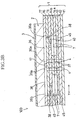
- the inspection-related grooves 50 can be formed in the third spacer sheet 16 simultaneously when the through-holes 37 and the communication holes 38 are formed in the sheet 16; and in a modified embodiment shown in Fig. 3B, inspection-related grooves 60 can be formed in the base sheet 17 simultaneously when the recesses defining the pressure chambers 36 are formed in the sheet 17.
- the piezoelectric actuator 2 includes a plurality of piezoelectric sheets, not shown, which are stacked on each other, and additionally includes a top sheet 25 (Fig. 1) which is stacked on the piezoelectric sheets.
- Each of the piezoelectric sheets has a thickness of about 30 ⁇ m.
- An internal-individual-electrode layer i.e., five arrays of internal individual electrodes, not shown, are provided on an upper planar surface of each of the lowermost piezoelectric sheet and every second piezoelectric sheets counted from the lowermost sheet, at respective positions corresponding to the pressure chambers 36 of the channel unit 1, such that the five arrays of internal individual electrodes extend in a lengthwise direction of the piezoelectric actuator 2, i.e., in the X direction, and such that each of the internal individual electrodes has a small width and extends in the Y direction perpendicular to the X direction.
- an internal common electrode which is common to all the pressure chambers 36 is provided on an upper planar surface of each of the other piezoelectric sheets of the piezoelectric actuator 2.
- an internal common electrode On an upper planar surface of the top sheet 25 of the piezoelectric actuator 2, there are provided five arrays of external individual electrodes 26 that are electrically connected to the five arrays of individual electrodes of each one of the internal-individual-electrode layers, and an external common electrode 27 that is electrically connected to each one of the internal common electrodes.
- the piezoelectric actuator 2 may be replaced with a different sort of piezoelectric actuator having such a structure in which a greater number of piezoelectric sheets are stacked on each other, as disclosed by Japanese Patent Application Publication No. 4-341853 or its corresponding U.S. Patent No. 5,402,159.
- An adhesive sheet not shown, formed of an ink-impermeable synthetic resin as a sort of adhesive material, is adhered, in advance, to an entire lower planar surface of the sheet-type piezoelectric actuator 2 that is to be opposed to the pressure chambers 36 of the channel unit 1. Subsequently, in a state in which the internal individual electrodes of the piezoelectric actuator 2 are aligned with the pressure chambers 36 of the channel unit 1, respectively, the actuator 2 is adhered, and thereby fixed, to the upper surface of the channel unit 1.
- the flexible flat cable 3 is stacked on, and bonded to, the upper surface of the piezoelectric actuator 2, such that a plurality of electric wires, not shown, of the flat cable 3 are electrically connected to the individual and common external electrodes 26, 27 of the actuator 2.
- the adhesion of the base sheet 17 and the second spacer sheet 16 is so defective that two pressure chambers 36 belonging to a pair of adjacent arrays communicate with each other via one or more leakage routes produced in the area W located between the pair of adjacent arrays of pressure chambers 36, some amount of the pressurized air charged into the pressure chambers 36 leaks via the leakage routes into a corresponding one of the inspection-related grooves 50, and eventually flows out of the open end 50a of the one groove 50.
- the defect of the fluid tightness in the area W can be found by detecting the flowing of air out of the open end 50a of each inspection-related groove 50, or alternatively detecting the lowering of pressure of the air in each ink inlet 47.
- the flexible flat cable 3 is bonded to the bonded body
- the bonded body of the channel unit 1 and the piezoelectric actuator 2 has the one inspection-related groove 50 located between the two adjacent arrays of pressure chambers 36 that communicate with the two adjacent common ink chambers 7, respectively, that are commonly connected to the one ink inlet 47a.
- the defect of the fluid tightness in the area W located between those adjacent arrays of pressure chambers 36 cannot be detected.
- the bonded body of the elements 1, 2 has the one inspection-related groove 50, the defect of the fluid tightness in the area W can be detected.
- the bonded body of the channel unit 1 and the piezoelectric actuator 2 is found to have the defect, the bonded body is discarded before the flexible flat cable 3 is bonded to the same. Therefore, the yield of the ink jet printer heads 100 as final products can be improved.
- the fluid used to inspect the channel unit 1, or the bonded body of the channel unit 1 and the piezoelectric actuator 2 is not limited to air or a different kind of gas, such as an inert gas, but it may be an appropriate kind of liquid such as water.
- each inspection-related groove 50 is not limited to the straight shape shown in Figs. 4 and 5, but each groove 50 may take an arbitrary shape, such as a circular shape or a polygonal shape, depending upon a shape of one or more reference lines along which the pressure chambers 36 are arranged, so long as it communicates with an outside space of the ink jet printer head 100.
- Each inspection-related groove 50 may have the smallest possible cross-section area that allows a fluid to smoothly flow out of the open end 50a thereof.
- the inspection-related grooves 50 are formed in the adhesion interface of the base sheet 17 and the third spacer sheet 16.
- the inspection-related grooves 60 may be formed in the adhesion interface of the base sheet 17 and the lower planar surface of the lowermost sheet member (e.g., the lowermost piezoelectric sheet) of the piezoelectric actuator 2, or in each of the adhesion interface of the two sheet members 16, 17 and the adhesion interface of the base sheet 17 and the actuator 2.
- the inspection-related grooves 50, 60 are formed in the upper planar surface of the third spacer sheet 16 or the base sheet 17.
- the inspection-related grooves 50, 60 may be formed in at least one of the upper planar surface of the third spacer sheet 16, the lower planar surface of the base sheet 17, the upper planar surface of the base sheet 17, and the lower planar surface of the lowermost sheet member of the piezoelectric actuator 2.
- each pair of adjacent arrays of pressure chambers 36 of the channel unit 1 there is provided one inspection-related groove 50. That is, the four grooves 50 are provided among the five arrays of pressure chambers 50.
Landscapes
- Particle Formation And Scattering Control In Inkjet Printers (AREA)
Applications Claiming Priority (2)
| Application Number | Priority Date | Filing Date | Title |
|---|---|---|---|
| JP2003331226A JP2005096171A (ja) | 2003-09-24 | 2003-09-24 | インクジェットプリンタヘッド及びその検査方法 |
| JP2003331226 | 2003-09-24 |
Publications (2)
| Publication Number | Publication Date |
|---|---|
| EP1518682A1 true EP1518682A1 (de) | 2005-03-30 |
| EP1518682B1 EP1518682B1 (de) | 2007-11-21 |
Family
ID=34191441
Family Applications (1)
| Application Number | Title | Priority Date | Filing Date |
|---|---|---|---|
| EP04022227A Expired - Lifetime EP1518682B1 (de) | 2003-09-24 | 2004-09-17 | Tintenstrahldruckkopf und dazugehöriges Überprüfungsverfahren |
Country Status (4)
| Country | Link |
|---|---|
| US (1) | US7168792B2 (de) |
| EP (1) | EP1518682B1 (de) |
| JP (1) | JP2005096171A (de) |
| DE (1) | DE602004010215T2 (de) |
Families Citing this family (10)
| Publication number | Priority date | Publication date | Assignee | Title |
|---|---|---|---|---|
| JP4243850B2 (ja) * | 2004-05-11 | 2009-03-25 | ブラザー工業株式会社 | 積層型圧電素子及びそれを備えたインクジェット記録ヘッド |
| KR100694132B1 (ko) * | 2005-06-28 | 2007-03-12 | 삼성전자주식회사 | 잉크 카트리지의 잉크 채널 유닛과 그 제조 방법 |
| JP4848746B2 (ja) * | 2005-11-28 | 2011-12-28 | ブラザー工業株式会社 | 吐出タイミング決定方法 |
| JP2007196593A (ja) | 2006-01-27 | 2007-08-09 | Brother Ind Ltd | インクジェットヘッド及びインクジェット記録装置 |
| JP2008023768A (ja) * | 2006-07-19 | 2008-02-07 | Brother Ind Ltd | ヘッドユニットの厚さの管理方法および製造方法 |
| JP4872562B2 (ja) | 2006-09-25 | 2012-02-08 | ブラザー工業株式会社 | 液体吐出装置用ヘッド |
| JP5200397B2 (ja) * | 2007-03-20 | 2013-06-05 | ブラザー工業株式会社 | 液滴吐出装置 |
| JP6122298B2 (ja) * | 2013-01-09 | 2017-04-26 | エスアイアイ・プリンテック株式会社 | ヘッドチップの製造方法 |
| JP6870221B2 (ja) * | 2016-06-24 | 2021-05-12 | コニカミノルタ株式会社 | インクジェット記録装置及びインクジェット記録装置の異常検出方法 |
| JP7689053B2 (ja) * | 2021-10-14 | 2025-06-05 | エスアイアイ・プリンテック株式会社 | ヘッドチップ、液体噴射ヘッド、液体噴射記録装置およびヘッドチップの製造方法 |
Citations (10)
| Publication number | Priority date | Publication date | Assignee | Title |
|---|---|---|---|---|
| EP0357020A2 (de) * | 1988-09-01 | 1990-03-07 | Tektronix Inc. | Herstellung von Farbstrahldruckköpfen durch Diffusionsschweissung und Hartlötung |
| JPH0939233A (ja) * | 1995-07-27 | 1997-02-10 | Brother Ind Ltd | インクジェットヘッド |
| EP0916500A2 (de) * | 1997-11-17 | 1999-05-19 | Seiko Epson Corporation | Verfahren zur Thermischer Behandlung der Betätiger eines Tintenstrahldruckkopfes und Verfahren zur Herstellung eines Tintestrahldruckkopfes |
| EP0943440A2 (de) * | 1998-03-20 | 1999-09-22 | Nec Corporation | Tintenstrahlaufzeichnungskopf und Herstellungsverfahren |
| JP2001260349A (ja) | 2000-03-15 | 2001-09-25 | Brother Ind Ltd | 圧電式インクジェットプリンタヘッドにおけるプレート型圧電アクチェータ及びその製造方法 |
| US6328434B1 (en) * | 1999-07-01 | 2001-12-11 | Fujitsu Limited | Inkjet head, its manufacturing method and recording device |
| US6361155B1 (en) * | 1999-06-23 | 2002-03-26 | Nec Corporation | Ink jet recording head and method for manufacturing the same |
| US20020036678A1 (en) * | 2000-09-22 | 2002-03-28 | Brother Kogyo Kabushiki Kaisha | Laminated and bonded construction of thin plate parts |
| US6412334B1 (en) * | 2000-02-07 | 2002-07-02 | Steris Inc. | Leak detector for endoscopes |
| US6604817B2 (en) | 2000-03-07 | 2003-08-12 | Brother Kogyo Kabushiki Kaisha | Print head for piezoelectric ink jet printer, piezoelectric actuator therefor, and process for producing piezoelectric actuator |
Family Cites Families (5)
| Publication number | Priority date | Publication date | Assignee | Title |
|---|---|---|---|---|
| US5402159A (en) | 1990-03-26 | 1995-03-28 | Brother Kogyo Kabushiki Kaisha | Piezoelectric ink jet printer using laminated piezoelectric actuator |
| JPH04341853A (ja) | 1991-05-20 | 1992-11-27 | Brother Ind Ltd | 圧電式インクジェットプリンタヘッド |
| JP3345294B2 (ja) * | 1997-02-20 | 2002-11-18 | ブラザー工業株式会社 | インクジェット式記録ヘッドの製造方法及びその記録ヘッド |
| JP4570178B2 (ja) * | 1998-11-26 | 2010-10-27 | 富士フイルム株式会社 | インクジェットヘッドとその製造方法、印刷装置 |
| JP3327246B2 (ja) * | 1999-03-25 | 2002-09-24 | 富士ゼロックス株式会社 | インクジェット記録ヘッド及びその製造方法 |
-
2003
- 2003-09-24 JP JP2003331226A patent/JP2005096171A/ja active Pending
-
2004
- 2004-09-16 US US10/944,355 patent/US7168792B2/en not_active Expired - Lifetime
- 2004-09-17 DE DE602004010215T patent/DE602004010215T2/de not_active Expired - Lifetime
- 2004-09-17 EP EP04022227A patent/EP1518682B1/de not_active Expired - Lifetime
Patent Citations (10)
| Publication number | Priority date | Publication date | Assignee | Title |
|---|---|---|---|---|
| EP0357020A2 (de) * | 1988-09-01 | 1990-03-07 | Tektronix Inc. | Herstellung von Farbstrahldruckköpfen durch Diffusionsschweissung und Hartlötung |
| JPH0939233A (ja) * | 1995-07-27 | 1997-02-10 | Brother Ind Ltd | インクジェットヘッド |
| EP0916500A2 (de) * | 1997-11-17 | 1999-05-19 | Seiko Epson Corporation | Verfahren zur Thermischer Behandlung der Betätiger eines Tintenstrahldruckkopfes und Verfahren zur Herstellung eines Tintestrahldruckkopfes |
| EP0943440A2 (de) * | 1998-03-20 | 1999-09-22 | Nec Corporation | Tintenstrahlaufzeichnungskopf und Herstellungsverfahren |
| US6361155B1 (en) * | 1999-06-23 | 2002-03-26 | Nec Corporation | Ink jet recording head and method for manufacturing the same |
| US6328434B1 (en) * | 1999-07-01 | 2001-12-11 | Fujitsu Limited | Inkjet head, its manufacturing method and recording device |
| US6412334B1 (en) * | 2000-02-07 | 2002-07-02 | Steris Inc. | Leak detector for endoscopes |
| US6604817B2 (en) | 2000-03-07 | 2003-08-12 | Brother Kogyo Kabushiki Kaisha | Print head for piezoelectric ink jet printer, piezoelectric actuator therefor, and process for producing piezoelectric actuator |
| JP2001260349A (ja) | 2000-03-15 | 2001-09-25 | Brother Ind Ltd | 圧電式インクジェットプリンタヘッドにおけるプレート型圧電アクチェータ及びその製造方法 |
| US20020036678A1 (en) * | 2000-09-22 | 2002-03-28 | Brother Kogyo Kabushiki Kaisha | Laminated and bonded construction of thin plate parts |
Also Published As
| Publication number | Publication date |
|---|---|
| JP2005096171A (ja) | 2005-04-14 |
| DE602004010215T2 (de) | 2008-03-13 |
| EP1518682B1 (de) | 2007-11-21 |
| US7168792B2 (en) | 2007-01-30 |
| DE602004010215D1 (de) | 2008-01-03 |
| US20050062805A1 (en) | 2005-03-24 |
Similar Documents
| Publication | Publication Date | Title |
|---|---|---|
| US7614719B2 (en) | Inkjet printer and inkjet head with modification of driving waveform data | |
| JP5019061B2 (ja) | 液体噴射ヘッド及びその製造方法並びに液体噴射装置 | |
| US7121643B2 (en) | Ink-jet printing head | |
| JP5845122B2 (ja) | ヘッドチップ、液体噴射ヘッド及び液体噴射記録装置 | |
| EP1518682B1 (de) | Tintenstrahldruckkopf und dazugehöriges Überprüfungsverfahren | |
| EP1547775A1 (de) | Tintenstrahlkopf | |
| US7992970B2 (en) | Droplet ejecting apparatus | |
| JP2010201730A (ja) | 液体吐出ヘッド及びこれを含む記録装置の製造方法、並びに、液体吐出ヘッド及び記録装置 | |
| US6846069B2 (en) | Ink-jet head | |
| US7431444B2 (en) | Inkjet head with filter for ink supply openings | |
| JP4720916B2 (ja) | 記録装置 | |
| US7690770B2 (en) | Sheet-member stacked structure, lead frame, lead-frame stacked structure, sheet-member stacked and adhered structure, and ink jet printer head | |
| JP4235819B2 (ja) | インクジェット式記録ヘッド | |
| US7344229B2 (en) | Inkjet recording head and head unit | |
| JP2003326702A (ja) | インクジェットヘッド | |
| EP1361062B1 (de) | Tintenstrahlkopf | |
| US7681999B2 (en) | Ink-jet printing head | |
| EP1964681B1 (de) | Fluidkanaleinheit für eine Fluidausgabevorrichtung | |
| JP6935828B2 (ja) | 液体吐出装置及び液体吐出装置ユニット | |
| JP4680805B2 (ja) | インクジェットヘッド | |
| JP4946389B2 (ja) | 吐出タイミング決定方法及び液滴吐出方法 | |
| JP2008200910A (ja) | 液体噴射ヘッドの検査方法及びその検査装置 | |
| US20060092238A1 (en) | Inkjet printhead | |
| JP3997829B2 (ja) | インクジェットヘッド | |
| JP2009107255A (ja) | 液滴吐出ヘッドの不良ノズル検出方法 |
Legal Events
| Date | Code | Title | Description |
|---|---|---|---|
| PUAI | Public reference made under article 153(3) epc to a published international application that has entered the european phase |
Free format text: ORIGINAL CODE: 0009012 |
|
| AK | Designated contracting states |
Kind code of ref document: A1 Designated state(s): AT BE BG CH CY CZ DE DK EE ES FI FR GB GR HU IE IT LI LU MC NL PL PT RO SE SI SK TR |
|
| AX | Request for extension of the european patent |
Extension state: AL HR LT LV MK |
|
| 17P | Request for examination filed |
Effective date: 20050615 |
|
| AKX | Designation fees paid |
Designated state(s): AT BE BG CH CY CZ DE DK EE ES FI FR GB GR HU IE IT LI LU MC NL PL PT RO SE SI SK TR |
|
| 17Q | First examination report despatched |
Effective date: 20060721 |
|
| GRAP | Despatch of communication of intention to grant a patent |
Free format text: ORIGINAL CODE: EPIDOSNIGR1 |
|
| GRAS | Grant fee paid |
Free format text: ORIGINAL CODE: EPIDOSNIGR3 |
|
| GRAA | (expected) grant |
Free format text: ORIGINAL CODE: 0009210 |
|
| AK | Designated contracting states |
Kind code of ref document: B1 Designated state(s): AT BE BG CH CY CZ DE DK EE ES FI FR GB GR HU IE IT LI LU MC NL PL PT RO SE SI SK TR |
|
| REG | Reference to a national code |
Ref country code: GB Ref legal event code: FG4D |
|
| REG | Reference to a national code |
Ref country code: IE Ref legal event code: FG4D |
|
| REG | Reference to a national code |
Ref country code: CH Ref legal event code: EP |
|
| REF | Corresponds to: |
Ref document number: 602004010215 Country of ref document: DE Date of ref document: 20080103 Kind code of ref document: P |
|
| PG25 | Lapsed in a contracting state [announced via postgrant information from national office to epo] |
Ref country code: NL Free format text: LAPSE BECAUSE OF FAILURE TO SUBMIT A TRANSLATION OF THE DESCRIPTION OR TO PAY THE FEE WITHIN THE PRESCRIBED TIME-LIMIT Effective date: 20071121 Ref country code: LI Free format text: LAPSE BECAUSE OF FAILURE TO SUBMIT A TRANSLATION OF THE DESCRIPTION OR TO PAY THE FEE WITHIN THE PRESCRIBED TIME-LIMIT Effective date: 20071121 Ref country code: ES Free format text: LAPSE BECAUSE OF FAILURE TO SUBMIT A TRANSLATION OF THE DESCRIPTION OR TO PAY THE FEE WITHIN THE PRESCRIBED TIME-LIMIT Effective date: 20080304 Ref country code: SE Free format text: LAPSE BECAUSE OF FAILURE TO SUBMIT A TRANSLATION OF THE DESCRIPTION OR TO PAY THE FEE WITHIN THE PRESCRIBED TIME-LIMIT Effective date: 20080221 Ref country code: CH Free format text: LAPSE BECAUSE OF FAILURE TO SUBMIT A TRANSLATION OF THE DESCRIPTION OR TO PAY THE FEE WITHIN THE PRESCRIBED TIME-LIMIT Effective date: 20071121 |
|
| NLV1 | Nl: lapsed or annulled due to failure to fulfill the requirements of art. 29p and 29m of the patents act | ||
| ET | Fr: translation filed | ||
| PG25 | Lapsed in a contracting state [announced via postgrant information from national office to epo] |
Ref country code: BG Free format text: LAPSE BECAUSE OF FAILURE TO SUBMIT A TRANSLATION OF THE DESCRIPTION OR TO PAY THE FEE WITHIN THE PRESCRIBED TIME-LIMIT Effective date: 20080221 Ref country code: SI Free format text: LAPSE BECAUSE OF FAILURE TO SUBMIT A TRANSLATION OF THE DESCRIPTION OR TO PAY THE FEE WITHIN THE PRESCRIBED TIME-LIMIT Effective date: 20071121 Ref country code: FI Free format text: LAPSE BECAUSE OF FAILURE TO SUBMIT A TRANSLATION OF THE DESCRIPTION OR TO PAY THE FEE WITHIN THE PRESCRIBED TIME-LIMIT Effective date: 20071121 Ref country code: PL Free format text: LAPSE BECAUSE OF FAILURE TO SUBMIT A TRANSLATION OF THE DESCRIPTION OR TO PAY THE FEE WITHIN THE PRESCRIBED TIME-LIMIT Effective date: 20071121 |
|
| REG | Reference to a national code |
Ref country code: CH Ref legal event code: PL |
|
| PG25 | Lapsed in a contracting state [announced via postgrant information from national office to epo] |
Ref country code: AT Free format text: LAPSE BECAUSE OF FAILURE TO SUBMIT A TRANSLATION OF THE DESCRIPTION OR TO PAY THE FEE WITHIN THE PRESCRIBED TIME-LIMIT Effective date: 20071121 |
|
| PG25 | Lapsed in a contracting state [announced via postgrant information from national office to epo] |
Ref country code: CZ Free format text: LAPSE BECAUSE OF FAILURE TO SUBMIT A TRANSLATION OF THE DESCRIPTION OR TO PAY THE FEE WITHIN THE PRESCRIBED TIME-LIMIT Effective date: 20071121 Ref country code: DK Free format text: LAPSE BECAUSE OF FAILURE TO SUBMIT A TRANSLATION OF THE DESCRIPTION OR TO PAY THE FEE WITHIN THE PRESCRIBED TIME-LIMIT Effective date: 20071121 |
|
| PG25 | Lapsed in a contracting state [announced via postgrant information from national office to epo] |
Ref country code: RO Free format text: LAPSE BECAUSE OF FAILURE TO SUBMIT A TRANSLATION OF THE DESCRIPTION OR TO PAY THE FEE WITHIN THE PRESCRIBED TIME-LIMIT Effective date: 20071121 Ref country code: SK Free format text: LAPSE BECAUSE OF FAILURE TO SUBMIT A TRANSLATION OF THE DESCRIPTION OR TO PAY THE FEE WITHIN THE PRESCRIBED TIME-LIMIT Effective date: 20071121 Ref country code: BE Free format text: LAPSE BECAUSE OF FAILURE TO SUBMIT A TRANSLATION OF THE DESCRIPTION OR TO PAY THE FEE WITHIN THE PRESCRIBED TIME-LIMIT Effective date: 20071121 |
|
| PLBE | No opposition filed within time limit |
Free format text: ORIGINAL CODE: 0009261 |
|
| STAA | Information on the status of an ep patent application or granted ep patent |
Free format text: STATUS: NO OPPOSITION FILED WITHIN TIME LIMIT |
|
| PG25 | Lapsed in a contracting state [announced via postgrant information from national office to epo] |
Ref country code: PT Free format text: LAPSE BECAUSE OF FAILURE TO SUBMIT A TRANSLATION OF THE DESCRIPTION OR TO PAY THE FEE WITHIN THE PRESCRIBED TIME-LIMIT Effective date: 20080421 |
|
| 26N | No opposition filed |
Effective date: 20080822 |
|
| PG25 | Lapsed in a contracting state [announced via postgrant information from national office to epo] |
Ref country code: GR Free format text: LAPSE BECAUSE OF FAILURE TO SUBMIT A TRANSLATION OF THE DESCRIPTION OR TO PAY THE FEE WITHIN THE PRESCRIBED TIME-LIMIT Effective date: 20080222 |
|
| PG25 | Lapsed in a contracting state [announced via postgrant information from national office to epo] |
Ref country code: MC Free format text: LAPSE BECAUSE OF NON-PAYMENT OF DUE FEES Effective date: 20080930 Ref country code: EE Free format text: LAPSE BECAUSE OF FAILURE TO SUBMIT A TRANSLATION OF THE DESCRIPTION OR TO PAY THE FEE WITHIN THE PRESCRIBED TIME-LIMIT Effective date: 20071121 |
|
| PG25 | Lapsed in a contracting state [announced via postgrant information from national office to epo] |
Ref country code: IE Free format text: LAPSE BECAUSE OF NON-PAYMENT OF DUE FEES Effective date: 20080917 Ref country code: CY Free format text: LAPSE BECAUSE OF FAILURE TO SUBMIT A TRANSLATION OF THE DESCRIPTION OR TO PAY THE FEE WITHIN THE PRESCRIBED TIME-LIMIT Effective date: 20071121 |
|
| PG25 | Lapsed in a contracting state [announced via postgrant information from national office to epo] |
Ref country code: HU Free format text: LAPSE BECAUSE OF FAILURE TO SUBMIT A TRANSLATION OF THE DESCRIPTION OR TO PAY THE FEE WITHIN THE PRESCRIBED TIME-LIMIT Effective date: 20080522 Ref country code: LU Free format text: LAPSE BECAUSE OF NON-PAYMENT OF DUE FEES Effective date: 20080917 |
|
| PG25 | Lapsed in a contracting state [announced via postgrant information from national office to epo] |
Ref country code: TR Free format text: LAPSE BECAUSE OF FAILURE TO SUBMIT A TRANSLATION OF THE DESCRIPTION OR TO PAY THE FEE WITHIN THE PRESCRIBED TIME-LIMIT Effective date: 20071121 |
|
| PG25 | Lapsed in a contracting state [announced via postgrant information from national office to epo] |
Ref country code: IT Free format text: LAPSE BECAUSE OF NON-PAYMENT OF DUE FEES Effective date: 20080930 |
|
| REG | Reference to a national code |
Ref country code: FR Ref legal event code: PLFP Year of fee payment: 13 |
|
| REG | Reference to a national code |
Ref country code: FR Ref legal event code: PLFP Year of fee payment: 14 |
|
| REG | Reference to a national code |
Ref country code: FR Ref legal event code: PLFP Year of fee payment: 15 |
|
| PGFP | Annual fee paid to national office [announced via postgrant information from national office to epo] |
Ref country code: FR Payment date: 20190819 Year of fee payment: 16 |
|
| PGFP | Annual fee paid to national office [announced via postgrant information from national office to epo] |
Ref country code: GB Payment date: 20190827 Year of fee payment: 16 |
|
| GBPC | Gb: european patent ceased through non-payment of renewal fee |
Effective date: 20200917 |
|
| PG25 | Lapsed in a contracting state [announced via postgrant information from national office to epo] |
Ref country code: FR Free format text: LAPSE BECAUSE OF NON-PAYMENT OF DUE FEES Effective date: 20200930 |
|
| PG25 | Lapsed in a contracting state [announced via postgrant information from national office to epo] |
Ref country code: GB Free format text: LAPSE BECAUSE OF NON-PAYMENT OF DUE FEES Effective date: 20200917 |
|
| PGFP | Annual fee paid to national office [announced via postgrant information from national office to epo] |
Ref country code: DE Payment date: 20230808 Year of fee payment: 20 |
|
| REG | Reference to a national code |
Ref country code: DE Ref legal event code: R071 Ref document number: 602004010215 Country of ref document: DE |