EP1517165A2 - Gerät für die Spektroskopie - Google Patents
Gerät für die Spektroskopie Download PDFInfo
- Publication number
- EP1517165A2 EP1517165A2 EP04007157A EP04007157A EP1517165A2 EP 1517165 A2 EP1517165 A2 EP 1517165A2 EP 04007157 A EP04007157 A EP 04007157A EP 04007157 A EP04007157 A EP 04007157A EP 1517165 A2 EP1517165 A2 EP 1517165A2
- Authority
- EP
- European Patent Office
- Prior art keywords
- light
- optic
- beams
- splitting
- spectroscopic apparatus
- Prior art date
- Legal status (The legal status is an assumption and is not a legal conclusion. Google has not performed a legal analysis and makes no representation as to the accuracy of the status listed.)
- Ceased
Links
- 230000003287 optical effect Effects 0.000 claims abstract description 97
- 238000012545 processing Methods 0.000 claims abstract description 45
- 108091008695 photoreceptors Proteins 0.000 claims description 49
- 230000005684 electric field Effects 0.000 claims description 24
- 230000008859 change Effects 0.000 claims description 21
- 238000001228 spectrum Methods 0.000 claims description 13
- 230000005540 biological transmission Effects 0.000 claims description 12
- 239000002184 metal Substances 0.000 claims description 12
- 229910052751 metal Inorganic materials 0.000 claims description 12
- 239000000758 substrate Substances 0.000 claims description 10
- 239000000463 material Substances 0.000 claims description 7
- 230000003595 spectral effect Effects 0.000 claims description 5
- 230000000694 effects Effects 0.000 claims description 4
- 230000008021 deposition Effects 0.000 claims 1
- 238000002310 reflectometry Methods 0.000 abstract description 23
- 239000006185 dispersion Substances 0.000 abstract description 9
- 238000010586 diagram Methods 0.000 description 68
- 239000010408 film Substances 0.000 description 56
- 238000010276 construction Methods 0.000 description 24
- 239000011521 glass Substances 0.000 description 20
- 238000005259 measurement Methods 0.000 description 16
- 239000010931 gold Substances 0.000 description 12
- PCHJSUWPFVWCPO-UHFFFAOYSA-N gold Chemical compound [Au] PCHJSUWPFVWCPO-UHFFFAOYSA-N 0.000 description 11
- 229910052737 gold Inorganic materials 0.000 description 11
- 230000001419 dependent effect Effects 0.000 description 7
- 238000002789 length control Methods 0.000 description 7
- 239000013307 optical fiber Substances 0.000 description 7
- 238000001914 filtration Methods 0.000 description 6
- 230000000737 periodic effect Effects 0.000 description 6
- 238000004611 spectroscopical analysis Methods 0.000 description 5
- 238000000034 method Methods 0.000 description 4
- 239000000126 substance Substances 0.000 description 4
- 230000008901 benefit Effects 0.000 description 2
- BJQHLKABXJIVAM-UHFFFAOYSA-N bis(2-ethylhexyl) phthalate Chemical compound CCCCC(CC)COC(=O)C1=CC=CC=C1C(=O)OCC(CC)CCCC BJQHLKABXJIVAM-UHFFFAOYSA-N 0.000 description 2
- 230000001678 irradiating effect Effects 0.000 description 2
- 238000012986 modification Methods 0.000 description 2
- 230000004048 modification Effects 0.000 description 2
- 229910000530 Gallium indium arsenide Inorganic materials 0.000 description 1
- 238000010521 absorption reaction Methods 0.000 description 1
- 238000004458 analytical method Methods 0.000 description 1
- 230000008033 biological extinction Effects 0.000 description 1
- 230000000903 blocking effect Effects 0.000 description 1
- 238000004891 communication Methods 0.000 description 1
- 238000000151 deposition Methods 0.000 description 1
- 238000013461 design Methods 0.000 description 1
- 239000003989 dielectric material Substances 0.000 description 1
- 239000003814 drug Substances 0.000 description 1
- 239000000284 extract Substances 0.000 description 1
- AMGQUBHHOARCQH-UHFFFAOYSA-N indium;oxotin Chemical compound [In].[Sn]=O AMGQUBHHOARCQH-UHFFFAOYSA-N 0.000 description 1
- 238000003754 machining Methods 0.000 description 1
- 238000001320 near-infrared absorption spectroscopy Methods 0.000 description 1
- 210000000056 organ Anatomy 0.000 description 1
- 230000005855 radiation Effects 0.000 description 1
- 230000009467 reduction Effects 0.000 description 1
- 238000000926 separation method Methods 0.000 description 1
- 239000010409 thin film Substances 0.000 description 1
- 238000013519 translation Methods 0.000 description 1
- 238000002834 transmittance Methods 0.000 description 1
Images


Classifications
-
- G—PHYSICS
- G02—OPTICS
- G02B—OPTICAL ELEMENTS, SYSTEMS OR APPARATUS
- G02B6/00—Light guides; Structural details of arrangements comprising light guides and other optical elements, e.g. couplings
- G02B6/24—Coupling light guides
- G02B6/42—Coupling light guides with opto-electronic elements
- G02B6/4201—Packages, e.g. shape, construction, internal or external details
- G02B6/4246—Bidirectionally operating package structures
-
- G—PHYSICS
- G01—MEASURING; TESTING
- G01J—MEASUREMENT OF INTENSITY, VELOCITY, SPECTRAL CONTENT, POLARISATION, PHASE OR PULSE CHARACTERISTICS OF INFRARED, VISIBLE OR ULTRAVIOLET LIGHT; COLORIMETRY; RADIATION PYROMETRY
- G01J3/00—Spectrometry; Spectrophotometry; Monochromators; Measuring colours
- G01J3/12—Generating the spectrum; Monochromators
- G01J3/18—Generating the spectrum; Monochromators using diffraction elements, e.g. grating
-
- G—PHYSICS
- G01—MEASURING; TESTING
- G01J—MEASUREMENT OF INTENSITY, VELOCITY, SPECTRAL CONTENT, POLARISATION, PHASE OR PULSE CHARACTERISTICS OF INFRARED, VISIBLE OR ULTRAVIOLET LIGHT; COLORIMETRY; RADIATION PYROMETRY
- G01J3/00—Spectrometry; Spectrophotometry; Monochromators; Measuring colours
- G01J3/12—Generating the spectrum; Monochromators
- G01J3/26—Generating the spectrum; Monochromators using multiple reflection, e.g. Fabry-Perot interferometer, variable interference filters
-
- G—PHYSICS
- G01—MEASURING; TESTING
- G01J—MEASUREMENT OF INTENSITY, VELOCITY, SPECTRAL CONTENT, POLARISATION, PHASE OR PULSE CHARACTERISTICS OF INFRARED, VISIBLE OR ULTRAVIOLET LIGHT; COLORIMETRY; RADIATION PYROMETRY
- G01J3/00—Spectrometry; Spectrophotometry; Monochromators; Measuring colours
- G01J3/28—Investigating the spectrum
- G01J3/2803—Investigating the spectrum using photoelectric array detector
-
- G—PHYSICS
- G02—OPTICS
- G02B—OPTICAL ELEMENTS, SYSTEMS OR APPARATUS
- G02B27/00—Optical systems or apparatus not provided for by any of the groups G02B1/00 - G02B26/00, G02B30/00
- G02B27/0087—Phased arrays
-
- G—PHYSICS
- G02—OPTICS
- G02B—OPTICAL ELEMENTS, SYSTEMS OR APPARATUS
- G02B27/00—Optical systems or apparatus not provided for by any of the groups G02B1/00 - G02B26/00, G02B30/00
- G02B27/10—Beam splitting or combining systems
- G02B27/1086—Beam splitting or combining systems operating by diffraction only
-
- G—PHYSICS
- G02—OPTICS
- G02B—OPTICAL ELEMENTS, SYSTEMS OR APPARATUS
- G02B27/00—Optical systems or apparatus not provided for by any of the groups G02B1/00 - G02B26/00, G02B30/00
- G02B27/10—Beam splitting or combining systems
- G02B27/14—Beam splitting or combining systems operating by reflection only
- G02B27/144—Beam splitting or combining systems operating by reflection only using partially transparent surfaces without spectral selectivity
-
- G—PHYSICS
- G01—MEASURING; TESTING
- G01J—MEASUREMENT OF INTENSITY, VELOCITY, SPECTRAL CONTENT, POLARISATION, PHASE OR PULSE CHARACTERISTICS OF INFRARED, VISIBLE OR ULTRAVIOLET LIGHT; COLORIMETRY; RADIATION PYROMETRY
- G01J3/00—Spectrometry; Spectrophotometry; Monochromators; Measuring colours
- G01J3/12—Generating the spectrum; Monochromators
- G01J2003/1226—Interference filters
- G01J2003/1247—Tuning
-
- G—PHYSICS
- G01—MEASURING; TESTING
- G01J—MEASUREMENT OF INTENSITY, VELOCITY, SPECTRAL CONTENT, POLARISATION, PHASE OR PULSE CHARACTERISTICS OF INFRARED, VISIBLE OR ULTRAVIOLET LIGHT; COLORIMETRY; RADIATION PYROMETRY
- G01J3/00—Spectrometry; Spectrophotometry; Monochromators; Measuring colours
- G01J3/02—Details
- G01J3/0205—Optical elements not provided otherwise, e.g. optical manifolds, diffusers, windows
- G01J3/0208—Optical elements not provided otherwise, e.g. optical manifolds, diffusers, windows using focussing or collimating elements, e.g. lenses or mirrors; performing aberration correction
-
- G—PHYSICS
- G01—MEASURING; TESTING
- G01J—MEASUREMENT OF INTENSITY, VELOCITY, SPECTRAL CONTENT, POLARISATION, PHASE OR PULSE CHARACTERISTICS OF INFRARED, VISIBLE OR ULTRAVIOLET LIGHT; COLORIMETRY; RADIATION PYROMETRY
- G01J3/00—Spectrometry; Spectrophotometry; Monochromators; Measuring colours
- G01J3/02—Details
- G01J3/0286—Constructional arrangements for compensating for fluctuations caused by temperature, humidity or pressure, or using cooling or temperature stabilization of parts of the device; Controlling the atmosphere inside a spectrometer, e.g. vacuum
-
- G—PHYSICS
- G02—OPTICS
- G02B—OPTICAL ELEMENTS, SYSTEMS OR APPARATUS
- G02B6/00—Light guides; Structural details of arrangements comprising light guides and other optical elements, e.g. couplings
- G02B6/24—Coupling light guides
- G02B6/26—Optical coupling means
- G02B6/28—Optical coupling means having data bus means, i.e. plural waveguides interconnected and providing an inherently bidirectional system by mixing and splitting signals
- G02B6/293—Optical coupling means having data bus means, i.e. plural waveguides interconnected and providing an inherently bidirectional system by mixing and splitting signals with wavelength selective means
- G02B6/29304—Optical coupling means having data bus means, i.e. plural waveguides interconnected and providing an inherently bidirectional system by mixing and splitting signals with wavelength selective means operating by diffraction, e.g. grating
- G02B6/29305—Optical coupling means having data bus means, i.e. plural waveguides interconnected and providing an inherently bidirectional system by mixing and splitting signals with wavelength selective means operating by diffraction, e.g. grating as bulk element, i.e. free space arrangement external to a light guide
- G02B6/29311—Diffractive element operating in transmission
-
- G—PHYSICS
- G02—OPTICS
- G02B—OPTICAL ELEMENTS, SYSTEMS OR APPARATUS
- G02B6/00—Light guides; Structural details of arrangements comprising light guides and other optical elements, e.g. couplings
- G02B6/24—Coupling light guides
- G02B6/26—Optical coupling means
- G02B6/28—Optical coupling means having data bus means, i.e. plural waveguides interconnected and providing an inherently bidirectional system by mixing and splitting signals
- G02B6/293—Optical coupling means having data bus means, i.e. plural waveguides interconnected and providing an inherently bidirectional system by mixing and splitting signals with wavelength selective means
- G02B6/29346—Optical coupling means having data bus means, i.e. plural waveguides interconnected and providing an inherently bidirectional system by mixing and splitting signals with wavelength selective means operating by wave or beam interference
- G02B6/29358—Multiple beam interferometer external to a light guide, e.g. Fabry-Pérot, etalon, VIPA plate, OTDL plate, continuous interferometer, parallel plate resonator
-
- G—PHYSICS
- G02—OPTICS
- G02B—OPTICAL ELEMENTS, SYSTEMS OR APPARATUS
- G02B6/00—Light guides; Structural details of arrangements comprising light guides and other optical elements, e.g. couplings
- G02B6/24—Coupling light guides
- G02B6/26—Optical coupling means
- G02B6/28—Optical coupling means having data bus means, i.e. plural waveguides interconnected and providing an inherently bidirectional system by mixing and splitting signals
- G02B6/293—Optical coupling means having data bus means, i.e. plural waveguides interconnected and providing an inherently bidirectional system by mixing and splitting signals with wavelength selective means
- G02B6/29371—Optical coupling means having data bus means, i.e. plural waveguides interconnected and providing an inherently bidirectional system by mixing and splitting signals with wavelength selective means operating principle based on material dispersion
- G02B6/29373—Optical coupling means having data bus means, i.e. plural waveguides interconnected and providing an inherently bidirectional system by mixing and splitting signals with wavelength selective means operating principle based on material dispersion utilising a bulk dispersive element, e.g. prism
-
- G—PHYSICS
- G02—OPTICS
- G02B—OPTICAL ELEMENTS, SYSTEMS OR APPARATUS
- G02B6/00—Light guides; Structural details of arrangements comprising light guides and other optical elements, e.g. couplings
- G02B6/24—Coupling light guides
- G02B6/26—Optical coupling means
- G02B6/28—Optical coupling means having data bus means, i.e. plural waveguides interconnected and providing an inherently bidirectional system by mixing and splitting signals
- G02B6/293—Optical coupling means having data bus means, i.e. plural waveguides interconnected and providing an inherently bidirectional system by mixing and splitting signals with wavelength selective means
- G02B6/29379—Optical coupling means having data bus means, i.e. plural waveguides interconnected and providing an inherently bidirectional system by mixing and splitting signals with wavelength selective means characterised by the function or use of the complete device
- G02B6/29395—Optical coupling means having data bus means, i.e. plural waveguides interconnected and providing an inherently bidirectional system by mixing and splitting signals with wavelength selective means characterised by the function or use of the complete device configurable, e.g. tunable or reconfigurable
-
- G—PHYSICS
- G02—OPTICS
- G02F—OPTICAL DEVICES OR ARRANGEMENTS FOR THE CONTROL OF LIGHT BY MODIFICATION OF THE OPTICAL PROPERTIES OF THE MEDIA OF THE ELEMENTS INVOLVED THEREIN; NON-LINEAR OPTICS; FREQUENCY-CHANGING OF LIGHT; OPTICAL LOGIC ELEMENTS; OPTICAL ANALOGUE/DIGITAL CONVERTERS
- G02F1/00—Devices or arrangements for the control of the intensity, colour, phase, polarisation or direction of light arriving from an independent light source, e.g. switching, gating or modulating; Non-linear optics
- G02F1/01—Devices or arrangements for the control of the intensity, colour, phase, polarisation or direction of light arriving from an independent light source, e.g. switching, gating or modulating; Non-linear optics for the control of the intensity, phase, polarisation or colour
- G02F1/0147—Devices or arrangements for the control of the intensity, colour, phase, polarisation or direction of light arriving from an independent light source, e.g. switching, gating or modulating; Non-linear optics for the control of the intensity, phase, polarisation or colour based on thermo-optic effects
-
- G—PHYSICS
- G02—OPTICS
- G02F—OPTICAL DEVICES OR ARRANGEMENTS FOR THE CONTROL OF LIGHT BY MODIFICATION OF THE OPTICAL PROPERTIES OF THE MEDIA OF THE ELEMENTS INVOLVED THEREIN; NON-LINEAR OPTICS; FREQUENCY-CHANGING OF LIGHT; OPTICAL LOGIC ELEMENTS; OPTICAL ANALOGUE/DIGITAL CONVERTERS
- G02F1/00—Devices or arrangements for the control of the intensity, colour, phase, polarisation or direction of light arriving from an independent light source, e.g. switching, gating or modulating; Non-linear optics
- G02F1/01—Devices or arrangements for the control of the intensity, colour, phase, polarisation or direction of light arriving from an independent light source, e.g. switching, gating or modulating; Non-linear optics for the control of the intensity, phase, polarisation or colour
- G02F1/03—Devices or arrangements for the control of the intensity, colour, phase, polarisation or direction of light arriving from an independent light source, e.g. switching, gating or modulating; Non-linear optics for the control of the intensity, phase, polarisation or colour based on ceramics or electro-optical crystals, e.g. exhibiting Pockels effect or Kerr effect
-
- G—PHYSICS
- G02—OPTICS
- G02F—OPTICAL DEVICES OR ARRANGEMENTS FOR THE CONTROL OF LIGHT BY MODIFICATION OF THE OPTICAL PROPERTIES OF THE MEDIA OF THE ELEMENTS INVOLVED THEREIN; NON-LINEAR OPTICS; FREQUENCY-CHANGING OF LIGHT; OPTICAL LOGIC ELEMENTS; OPTICAL ANALOGUE/DIGITAL CONVERTERS
- G02F2201/00—Constructional arrangements not provided for in groups G02F1/00 - G02F7/00
- G02F2201/17—Multi-pass arrangements, i.e. arrangements to pass light a plurality of times through the same element, e.g. by using an enhancement cavity
-
- G—PHYSICS
- G02—OPTICS
- G02F—OPTICAL DEVICES OR ARRANGEMENTS FOR THE CONTROL OF LIGHT BY MODIFICATION OF THE OPTICAL PROPERTIES OF THE MEDIA OF THE ELEMENTS INVOLVED THEREIN; NON-LINEAR OPTICS; FREQUENCY-CHANGING OF LIGHT; OPTICAL LOGIC ELEMENTS; OPTICAL ANALOGUE/DIGITAL CONVERTERS
- G02F2203/00—Function characteristic
- G02F2203/05—Function characteristic wavelength dependent
- G02F2203/055—Function characteristic wavelength dependent wavelength filtering
Definitions
- This invention relates to a spectroscopic apparatus, and more particularly to a spectroscopic apparatus associated with spectroscopic measurement in general, in which spectroscopy is performed.
- Spectroscopy means operation of splitting light according to wavelength or frequency, and is utilized for optical measurement in analyzing and measuring the structure of a substance, etc. Spectrometry is widely used in various fields, including medicine and engineering.
- Spectrometry includes a pre-splitting method in which light having a continuous spectrum is split and then irradiated onto a sample, and a post-splitting method in which light having a continuous spectrum is irradiated onto a sample without splitting the same and the resulting transmitted/reflected light is split.
- the spectroscopic characteristics of a substance can be represented by a spectrum or spectra of light, and therefore, it is possible to study the structure of a substance or chemical phenomena by analyzing the spectrum or spectra of light.
- an organic molecule of an organ or the like has a near-infrared absorption characteristic of the molecule, and therefore, near-infrared spectrometry is utilized in analysis of the components of a tissue, by irradiating a near-infrared radiation (having a wavelength of 0.8 to 2.5 ⁇ m) onto a sample, and extracting spectroscopic information from the transmitted light or diffuse reflected light.
- a near-infrared radiation having a wavelength of 0.8 to 2.5 ⁇ m
- an optic called a diffraction grating is generally employed.
- a spectroscope using the diffraction grating performs splitting of light by irradiating the light onto the diffraction grating to thereby obtain diffracted beams having desired wavelengths.
- FIGS. 38 and 39 are diagrams showing diffracted beams formed by the diffraction grating.
- FIG. 38 shows diffracted beams formed by a diffraction grating G1 having a glass plate formed with e.g. four grooves formed per unit length
- FIG. 39 shows diffracted beams formed by a diffraction grating G2 having a glass plate formed with e.g. eight grooves per unit length.
- the magnitude of an opening angle (diffraction angle) between a split diffracted beam having a wavelength ⁇ 0 and a split diffracted beam having a wavelength ( ⁇ 0 + ⁇ ) depends on the number of grooves per unit length.
- a diffraction angle ⁇ 1 of the diffraction grating G1 having a smaller number of grooves is compared with a diffraction angle ⁇ 2 of the diffraction grating G2 having a larger number of grooves, there holds ⁇ 1 ⁇ ⁇ 2.
- the diffraction grating G1 has a smaller diffraction angle, for a photodetector 105 to discriminate the respective wavelengths ⁇ 0 and ( ⁇ 0 + ⁇ ), it is required that the distance over which the diffracted beams are transmitted to the photodetector 105 is long.
- the diffraction grating G2 has a larger diffraction angle, it is possible for the photodetector 105 to discriminate the respective wavelengths ⁇ 0 and ( ⁇ 0 + ⁇ ), with a shorter distance over which the beams are transmitted.
- the VIPA includes a wavelength dispersion element (VIPA plate) comprised of a glass plate and reflection films coated on both sides of the glass plate.
- VIPA plate wavelength dispersion element
- the VIPA receives a collected beam, and causes multiple reflections of the input beam to thereby split the input beam into a plurality of beams having respective wavelengths (see e.g. Japanese Unexamined Patent Publication (Kokai) No. 2000-28849 (Paragraph Nos. [0016] to [0107], FIG. 6).
- the VIPA is capable of wavelength splitting with a larger angular dispersion than the diffraction grating (capable of performing finer light splitting than the diffraction grating), and hence capable of reducing the size of the optical system. Therefore, the VIPA can be applied to a receiver that receives a wavelength-multiplexed signal transmitted by WDM (Wavelength Division Multiplex), whereby it is possible to reduce the size of the receiver and perform compensation for wavelength dispersion.
- WDM Widelength Division Multiplex
- the VIPA plate as a component of the VIPA is a period filter and the spectral angle of the beams split by the VIPA plate has a wavelength periodicity. Therefore, in a VIPA-based spectroscope, when an optical signal composed of beams in wavelength bands of ⁇ 1 to ⁇ n is inputted and each beam is split into light components, one of photoreceptors (PDs: Photo Diodes) constituting a photodetector receives a plurality of light components at the same position within a period of each of the wavelength bands of ⁇ 1 to ⁇ n.
- PDs Photo Diodes
- the VIPA-based spectroscope is required to receive a light component (optical spectrum) obtained by splitting one wavelength (band), which makes it impossible to use such a VIPA-based spectroscope as used in WDM as it is, for the spectroscopic apparatus for optical measurement.
- the present invention has been made in view of the above described points, and an object thereof is to provide a spectroscopic apparatus which is compact in size and performs high-precision light-splitting with a large angular dispersion.
- the present invention provides a spectroscopic apparatus that performs splitting of light.
- This spectroscopic apparatus comprises an optical input-processing section that forms a filtered transmitted light, and collects the filtered transmitted light to generate a collected beam, the optical input-processing section including a bandpass filter through which an input light is transmitted to form the filtered transmitted light, an optic that includes a first reflection surface and a second reflection surface and causes the collected beam incident thereon to undergo multiple reflections within an inner region between the first reflection surface and the second reflection surface, to thereby cause split beams to be emitted via the second reflection surface, and a control section that variably controls at least one of a filter characteristic of the bandpass filter and an optical length through the optic.
- FIG. 1 is a diagram showing the basic arrangement of a spectroscopic apparatus according to a first embodiment of the present invention, which is useful in explaining the principles of the present invention.
- the spectroscopic apparatus 1 is an apparatus associated with spectroscopic measurement in general, in which spectroscopy is performed, and is comprised of an optical input-processing section 10, an optic 20, a received light-processing section 30, and a control section 40.
- the optic 20 is hereinafter referred to as "the VIPA plate 20".
- the optical input-processing section 10 is comprised of a lens 11 (hereinafter referred to as "the collimating lens 11"), a front-side condenser lens 12 (hereinafter referred to as “the cylindrical lens 12"), and a bandpass filter 13, and the bandpass filter 13 is disposed between the collimating lens 11 and the cylindrical lens 12.
- the received light-processing section 30 is comprised of a rear-side condenser lens 31 (hereinafter, simply referred to as “the condenser lens 31”) and a photodetector 32.
- the collimating lens 11 changes light emitted from an optical fiber F into collimated light.
- the bandpass filter 13 passes a wavelength band of the collimated light at only one period (performs bandpass filtering), to thereby output a filtered transmitted light.
- the cylindrical lens (semi-cylindrical lens) 12 collects the filtered transmitted light in a one-dimensional direction (linearly) and emits a collected beam.
- the VIPA plate 20 is a glass plate having a first reflection surface 21 and a second reflection surface 22 which are high but asymmetrical in reflectivity, and a light incident window 23 through which the collected beam is incident thereon.
- the collected beam is subjected to multiple reflections within an inner region between the first reflection surface 21 and the second reflection surface 22, and the split light beams emerge from the second reflection surface 22.
- the first reflection surface 21 is a total reflection surface (having a reflectivity of 100%) or a highly reflective surface close in reflectivity to the total reflection
- the second reflection surface 22 is a highly reflective surface (having a reflectivity of 95% to 98%) which allows part of the incident light to pass.
- the first reflection surface 21 is referred to as "the reflection surface 21”
- the second reflection surface 22 is referred to as "the light splitting surface 22”.
- the collected beam from the cylindrical lens 12 enters the VIPA plate 20 via the light incident window 23, it undergoes multiple reflections within the inner region of the glass plate between the reflection surface 21 and the light splitting surface 22, and the split light beams emerge from the light splitting surface 22.
- the condenser lens 31 collects the light beams emitted from the VIPA plate 20.
- the photodetector 32 is comprised of a plurality of photoreceptors (PDs), and disposed at a focal length position of the condenser lens 31, for receiving the emitted beams to detect optical spectra (it should be noted that in the present invention, each photoreceptor receives a single wavelength component of a beam at one period.)
- the control section 40 variably controls at least one of the filtering characteristic of the bandpass filter 13, an optical length of light passing through the inside of the VIPA plate 20, and a photodetecting position where received light-processing section 30 detects the light beams.
- the control section 40 can be connected to a terminal unit, such as a personal computer, and can be controlled by external instructions given by an operator of the terminal unit (the control section 40 itself may be provided with the functions of the terminal unit).
- the light-splitting direction is referred to as "the Y direction”
- the direction of the optical axis is referred to as “the Z direction”
- a direction perpendicular to the light-splitting direction and the direction of the optical axis is referred to as "the X direction”.
- the diffuse light emitted from the optical fiber F is changed into collimated light by the collimating lens 11, and a single wavelength band at a predetermined period is extracted by the bandpass filter 13, whereby filtered transmitted light is outputted.
- the filtered transmitted light is collected in a one-dimensional direction into the collected beam by the cylindrical lens 12.
- the term "collected in a one-dimensional direction” here is intended to mean “collected in the Y direction by the cylindrical lens 12" (as if the light is compressed in the Y direction).
- the collected beam enters the VIPA plate 20, and emerges from the light splitting surface 22 while undergoing multiple reflections within the VIPA plate 20.
- the multiple reflections of the incident beam occur while the reflected beam is expanded to a small degree dependent on the thickness of the glass plate, so that split beams each having a diameter dependent on the thickness of the glass plate leak from the light splitting surface 22.
- the emitted light beams from the VIPA plate 20 are split in the Y direction, and therefore separation of the emitted light beams can be recognized when viewed from the X direction (from the direction perpendicular to the sheet of FIG. 1), but cannot be perceived when viewed from the Y direction.
- the light beams split by the VIPA plate 20 and emitted therefrom are collected in the X direction and the Y direction (as if compressed in the X direction and the Y direction), i.e. focused to a single point.
- the photodetector 32 is disposed at the focal length position where the beams are focused, so that each photoreceptor can receive a single wavelength component at one period (one repetition period).
- the photoreceptor 32c receives a beam having an intermediate wavelength ⁇ C, while the photoreceptors 32b and 32a receive beams ⁇ S1 and ⁇ S2 having shorter wavelengths ( ⁇ S2 ⁇ ⁇ S1), respectively.
- the photodetectors 32d and 32e receive beams ⁇ L1 and ⁇ L2 having longer wavelengths ( ⁇ L1 ⁇ ⁇ L2), respectively.
- FIG. 2 is a diagram showing the basic construction of the VIPA.
- the VIPA 100 is comprised of a cylindrical lens 101 and a VIPA plate 102.
- the cylindrical lens 101 is for collecting the input light.
- the VIPA plate 102 is a glass plate having a surface 102a coated with a reflection film having a reflectivity of 100% (or a reflection film having a reflectivity close to 100%), a surface 102b coated with a reflection film having a reflectivity of 95 to 98%, and a light incident window 102c.
- FIG. 3 is a diagram useful in explaining the outline of operation of the VIPA.
- a beam B1 collected by the cylindrical lens 101 enters the VIPA plate 102 via the light incident window 102c.
- the optical axis Z of the beam B1 has a small angle ⁇ of inclination with respect to a normal H to the VIPA plate 102.
- the surface 102a has a reflectivity of 100%
- the surface 102b has a reflectivity of 98%
- 2% of the beam B1 is emitted from the surface 102b with a beam diameter corresponding to the thickness of the glass plate (the beam emitted from the surface 102b is a round beam (collimated light beam) with a small expansion angle, and has a beam diameter dependent on the thickness of the glass plate).
- the remaining 98% of the beam B1, i.e. a beam B1a is reflected toward the surface 102a (beam B1a travels toward the surface 102a while expanding to a small degree dependent on the thickness of the glass plate).
- the surface 102a has a reflectivity of 100%, the beam B1a is totally reflected therefrom toward the surface 102b (beam B1a travels toward the surface 102b while expanding to a small degree dependent on the thickness of the glass plate). Then, 2% of the beam B1a is emitted from the surface 102b with a beam diameter dependent on the thickness of the glass plate. At this time, the position of a spot where the beam B1 emerges and a spot where the beam B1a emerges is displaced by a distance d.
- the beams emitted from the surface 102b at the fixed spacing intervals of the distance d can be regarded as beams emitted from virtual emission spots v1 to vn (up to v4 are shown in the illustrated example) arranged in an array of steps (from which comes the name of the VIPA (Virtually Imaged Phased Array).
- This behavior can be regarded as that of an echelon diffraction grating, and similarly thereto, the incident light is split and emitted as the separate beams.
- the virtual emission spots v1 to vn are arranged along the normal H to the VIPA plate 102 at fixed intervals of 2D.
- the other virtual emission points are also located at intervals of 2D.
- FIG. 4 is a diagram showing interference conditions of the VIPA 100.
- a beam B2a is assumed to have m wavelength cycles within a path t0 through the VIPA plate along the optical axis (the beam B2a is assumed to have an intermediate wavelength).
- the interference conditions between the beam B2a and a beam B2c shown below the beam B2a are satisfied such that the beams B2a and B2c are intensified by each other, since a path t2 (defined as a path in phase with the path t0) of the beam B2c is longer than the path t0, in order for the beam B2c to have m wavelength cycles within the path t2, it is required that the wavelength of the beam B2c is longer than the wavelength of the beam B2a.
- the interference conditions that the beams are intensified by each other are that the upper beams with reference to the optical axis have shorter wavelengths and the lower beams with reference to the same have longer wavelengths, so that the VIPA 102 emits beams having shorter wavelengths on the upper side with respect to the optical axis thereof, and beams having longer wavelengths on the lower side with respect to the optical axis thereof.
- FIG. 5 is a diagram showing a VIPA-based spectroscope.
- the VIPA-based spectroscope 110 using the VIPA plate 102 is comprised of an optical fiber F, a collimating lens 103, a cylindrical lens 101, a VIPA plate 102, a condenser lens 104, and a photodetector 105.
- the light emitted from the optical fiber F is formed into collimated light by the collimating lens 103, focused by the cylindrical lens 101, and then enters the VIPA plate 102.
- the beams split by the VIPA plate 102 are collected by the condenser lens 104.
- a photodetector 105 comprised of a plurality of photoreceptors is disposed at a location where the beams are collected by condenser lens 104.
- the VIPA-based spectroscope 110 can function as the spectroscope.
- the illustrated example of the photodetector 105 are receiving beams having a shorter wavelength ⁇ S, an intermediate wavelength ⁇ C, and a longer wavelength ⁇ L within a certain wavelength band.
- the VIPA plate 102 has a structure similar to an etalon (i.e. an optical resonator having a structure of two parallel mirrors opposed to each other, for selectively passing only components of light having integral multiples of a predetermined frequency, and blocking the other components), and the diffraction order employed is very large. Further, the slit spacing is determined by an angle of inclination of the VIPA plate 102, which is set to be equal to approximately 1. 5° to 4°, so that it is possible to realize very dense slits, which provides a very large diffraction angle.
- the VIPA-based spectroscope 110 is high in resolution, and the size of the optical system thereof can be reduced, which makes the VIPA-based spectroscope 110 advantageous over the spectroscopes using the diffraction grating, in many respects, and can be effectively applied to various fields.
- the VIPA-based spectroscope 110 is employed as it is for the apparatus for optical measurement, there are some problems.
- FIG. 6 is a diagram showing a period filter characteristic of the VIPA plate 102.
- the vertical axis represents transmittance and the horizontal axis represents wavelength.
- beams emerging from the VIPA plate 102 show a wavelength periodicity that beams having wavelengths ⁇ 1, ⁇ 2, ⁇ 3, ...
- the optical length of the light traveling within the VIPA plate 102 is proportional to the refractive index n of the glass plate of the VIPA plate 102 and the thickness D of the glass plate (optical length ⁇ n ⁇ D) and a wavelength period T depends on the optical length.
- the wavelength period is increased to 2T, so that from the VIPA plate 102, beams having wavelengths ⁇ 1, ⁇ 3, ⁇ 5, ..., are emitted.
- the wavelength period is increased to 4T, so that beams having wavelengths ⁇ 1, ⁇ 5, ⁇ 9 ..., are emitted.
- the VIPA plate 102 functions as a period filter, and the light emitted from the VIPA plate 102 has a wavelength periodicity. This is a drawback of the VIPA-based spectroscope 110 when it is used as a device for optical measurement.
- FIG. 7 is a diagram showing the relationship between light-splitting directions and periodicity. Illustration of lenses and other elements are omitted. To show the features of the period filter of the VIPA plate 102, the illustrated example shows a state of receiving light components of beams in wavelength bands ⁇ 1, ⁇ 2, and ⁇ 3.
- the photoreceptors constituting the photodetector 105 of the VIPA-based spectroscope 110 receive a light component of each of the wavelength bands ⁇ 1 to ⁇ 3 at an identical position in respect of period.
- FIG. 8 is a diagram showing a conceptual representation of light splitting, i.e. a state where beams formed by splitting a beam in one wavelength band ⁇ 1 are emitted and received by the photodetector. It is assumed here, for simplicity, that the photodetector 105 is formed by three photoreceptors 105a to 105c.
- the VIPA plate 102 splits a beam in one wavelength band ⁇ 1, and emits beams having e.g. a shorter wavelength ⁇ S, an intermediate wavelength ⁇ C, and a longer wavelength ⁇ L.
- the photoreceptor 105a, 105b and 105c receive the shorter wavelength ⁇ S, the intermediate wavelength ⁇ C and the longer wavelength ⁇ L, respectively.
- FIG. 9 is a drawing showing another conceptual representation of light splitting, in which beams formed by splitting beams in wavelength bands ⁇ 1, ⁇ 2, and ⁇ 3, are being received.
- the photoreceptor 105a receives beams having shorter wavelengths ⁇ S1 to ⁇ S3 within the wavelength bands ⁇ 1 to ⁇ 3
- the photoreceptor 105b receives beams having intermediate wavelengths ⁇ C1 to ⁇ C3 within the wavelength bands ⁇ 1 to ⁇ 3
- the photoreceptor 105c receives beams having longer wavelengths ⁇ L1 to ⁇ L3 within the wavelength bands ⁇ 1 to ⁇ 3.
- the VIPA plate 102 is a period filter, and the beams emitted therefrom have a wavelength periodicity. Therefore, when the VIPA plate 102 splits and filters beams of light incident thereon, which have wavelengths ⁇ 1 to ⁇ n, one of the photoreceptors constituting the photodetector 105 receives a plurality of light components within the wavelength bands ⁇ 1 to ⁇ n, respectively, at an identical position in respect of period, as shown in FIG. 9 (e.g. the photoreceptor 105a receives beams having the shorter wavelengths ⁇ S1 to ⁇ S3 of ⁇ 1 to ⁇ 3).
- one photoreceptor of the photodetector 105 receives light components at the same position within each period which are obtained by splitting beams of all wavelengths (channels). Therefore, when the VIPA-based spectroscope 110 is used in a WDM receiver or the like, as a device for optical communications, it has the advantage of being capable of collectively processing a plurality of channels.
- the VIPA-based spectroscope 110 which inputs a plurality of light components within each wavelength band to each photoreceptor, cannot be used as it is, for a spectroscope for optical measurement.
- the present invention provides, through application of the VIPA-based spectroscope 110, a high-precision spectroscopic apparatus which is compact in size with a large angular dispersion, and can be used for optical measurement in general.
- FIG. 10 is a diagram useful in explaining the function of the bandpass filter 13.
- the bandpass filter 13 extracts one wavelength band at one period, and allows the same to pass. For example, in the illustrated example, only a beam in a wavelength band ⁇ 5 is extracted from light ranging from a wavelength band ⁇ 1 to a wavelength band ⁇ n and allowed to pass.
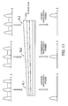
- FIG. 11 is a diagram showing the construction of the bandpass filter 13 and a state where wavelengths pass therethrough.
- the bandpass filter 13 is implemented by a sloped film 13a formed by sequentially depositing multiple films of a dielectric material each having a varying thickness such that the resulting multi-layered film is sloped.
- the wavelength bands of beams passing through the film 13a are different depending on the location of the slope where the light is incident.
- a slope location SL1 where the film has a smaller thickness
- a beam having a shorter wavelength passes.
- a beam having an intermediate wavelength passes.
- a beam having a longer wavelength passes.
- FIG. 12 is a diagram showing a moving control of the sloped film 13a.
- the sloped film 13a is configured such that it can be vertically moved in directions indicated by arrows in FIG. 12, to change the slope location where the light from the collimating lens 11 is incident, whereby it is possible to select and pass a beam having a desired wavelength (band).
- the sloped film 13a is equipped with a motor, and the motor is driven by a filtering characteristic-selecting signal from a control section 40, whereby the sloped film 13a is moved to a position where a beam in a predetermined wavelength band can be passed.
- a micrometer may be further provided, to enable fine adjustment of a vertical position of the sloped film 13a. Further, it is also possible to perform the fine adjustment of a wavelength band allowed to pass by adjusting not only the vertical position but also the inclination of the sloped film 13a with respect to the optical axis of light form the collimating lens 11.
- FIGS. 13 and 14 are diagrams showing variations of the bandpass filter 13.
- the bandpass filter 13 may be configured such that a plurality of filters are disposed in an array for selection so as to pass one of beams having different wavelengths which can be passed by the filters, respectively.
- the filter array shown in FIG. 13 is a linear array of filters 13b-1 to 13b-5, and the array can be vertically moved in directions indicated by arrows by a control signal from the control section 40, thereby making it possible to select a predetermined wavelength (band) allowed to pass.
- the filter array shown in FIG. 14 is a circular array of filters 13c-1 to 13c-5, and the array can be rotated in directions indicated by arrows by a control signal from the control section 40, thereby making it possible to select a predetermined wavelength (band) allowed to pass.
- FIG. 15 is a diagram showing a status of passage of one wavelength band.
- the transmission characteristic of the bandpass filter 13 is ideally rectangular, but in actuality, they are not rectangular but sloped to form a trapezoidal shape as can be resumed from FIG. 15.
- the shape of the wavelength band has a mountain shape, so that when the filtering-out of a wavelength band ⁇ b is carried out by the bandpass filter 13, there is a fear of end portions of wavelength bands ⁇ a or ⁇ c leaking into the passband. Therefore, it is necessary to change the interference conditions through control of the optical length through the VIPA plate 20, whereby the amount of leakage is controlled to be within a tolerance.
- FIG. 16 is a diagram showing a manner of shifting periodic wavelengths by optical length control.
- the wavelength transmission characteristic is shifted in a leftward or rightward as viewed in FIG. 16 (waveform of thin solid lines conceptually represents wavelength bands shifted in period).
- the optical length control can be carried out by making use of temperature or electric field. First, the optical length control using temperature will be described.
- FIG. 17 is a view showing a construction that changes the optical length through the VIPA plate 20.
- a container 200 includes a VIPA plate 20 and a heater 201, and glass windows 202 and 203 are formed at a light entrance and a light exit, respectively.
- the container 200 is formed as a thermostatic bath within which the VIPA plate 20 is gastightly sealed.
- the heater 201 is implemented e.g. by a Peltier device, and the temperature thereof is controlled by a control signal from the control section 40 to thereby uniformly control the temperature of VIPA plate 20.
- ⁇ the coefficient of linear expansion
- d ⁇ /dt the temperature coefficient of the refractive index
- n n0 + dn dt ⁇ t
- the product of multiplication of the equations (1) and (2) gives the optical length when the temperature rises by ⁇ t from the reference temperature, so that beams satisfying the interference conditions at this time are emitted from the VIPA plate 20.
- the temperature control thus performed enables the optical length through the VIPA plate 20 to be changed. It should be noted that temperature control devices other than the Peltier device may be used for the heater 201.
- the VIPA plate 20 can be configured such that it is made using a material having a large electrooptic effect, and the refractive index n of the substrate is changed by applying electric field thereto, to thereby control the optical length through the VIPA plate 20.
- a PLZT-based material PLZT Pb 1-x La x (Zr y Ti 1-y ) 1-x / 4 O 3 ), 0 ⁇ x ⁇ 0.28, 0 ⁇ y ⁇ 1.0, which is a ferroelectric material, satisfies the above conditions, and can be used in the present invention.
- FIG. 18 is a diagram showing a construction that changes the optical length through the VIPA plate 20 by using the electric field.
- electrically-conductive metal reflection films 204 of gold (Au) are coated on the reflection surface side and the light-splitting surface side thereof, to form the VIPA plate 20a.
- the metal reflection films 204 are caused to play the role of electrodes (the metal reflection films 204 are used as reflection film electrodes), and voltage is applied thereto under the control of the control section 40 to apply electric field to the VIPA plate 20a.
- FIG. 19 is a graph g1 showing the relationship between the reflectivity of the gold film and the film thickness.
- the vertical axis of the graph g1 represents reflectivity (%) and the horizontal axis of the same represents a film thickness (nm).
- FIG. 20 shows a table T1 showing the relationship between the reflectivity of the gold film and the film thickness. From the graph g1 and the table T1, it can be understood that when the thickness of the gold film becomes equal to or larger than 70 nm, the reflectivity of the film hardly changes.
- a gold film having a thickness of 70nm or larger is coated on the reflection surface side, and a gold film having a thickness of less than 70 nm is coated on the light-splitting surface side to thereby make the opposite sides asymmetric in respect of reflectivity, thereby realizing the control described above with reference to FIG. 18 (without providing a film having a reflectivity close to 100% on the reflection surface, by making both the reflection surface and the light-splitting surface high in reflectivity, and making the reflectivity of the reflection surface higher than that of the light-splitting surface, it is possible to sufficiently realize the function of the VIPA plate in a practical sense).
- FIG. 21 is a diagram showing a variation of the construction that changes the optical length.
- Multi-layered dielectric films 205 are coated on the reflection surface and the light-splitting surface of the substrate 24 of the VIPA plate, and transparent conductive films 206 are coated on the multi-layered dielectric films 205 to form a VIPA plate 20b.
- the transparent conductive films 206 there may be used ITO films (indium tin oxide film: thin film which is electrically-conductive and at the same time maintains the transparency of glass).
- FIG. 22 is a diagram showing a variation of the construction that changes the optical length.
- the multi-layered dielectric film 205 is coated, and at the same time, an ITO film 206 is coated on the multi-layered dielectric film 205.
- a metal reflection film 204 such as a gold film, is coated as the electrically-conductive film, whereby the VIPA plate 20c is formed.
- the ITO film 206 and the metal reflection film 204 are used as the electrodes, and voltage is applied thereto by the control section 40, whereby electric field is applied to the VIPA plate 20c.
- the control of the optical length is performed not only to suppress the amount of leakage of portions of adjacent wavelengths into the transmission wavelength, but also to impart the VIPA plate 20 a desired wavelength periodicity as shown in FIG. 6.
- the bandpass filter 13 is provided at a stage preceding the VIPA plate 20, whereby only a beam in one wavelength band at a predetermined period is extracted and caused to enter the VIPA plate 20.
- the VIPA is configured such that a wavelength (band) to be allowed to pass can be selected as desired by the control section 40, and the optical length can be variably set by temperature control of the VIPA plate 20 or by changing electric field applied thereto. This makes it possible to extract and split a beam in a wavelength band at a singe period, which provides a solution to the problem of a single photoreceptor receiving a plurality of spectral components in wavelength bands at a plurality of periods.
- FIG. 23 is a diagram showing the construction of the photodetector 32.
- the photodetector 32 is comprised of an array of a plurality of photoreceptors (PDs) in a one-dimensional direction, and the photoreceptors separately receive split beams having respective wavelengths, via the condenser lens 31.
- PDs photoreceptors
- FIG. 24 is a diagram showing the construction of the photodetector.
- the photodetector is formed by a single photoreceptor (PD) 32, and by providing a motor or the like for the photoreceptor 32a, the photodetector is moved in a one-dimensional direction by the control from the control section 40, whereby each split beam having a different wavelength is received by the photoreceptor 32a.
- PD photoreceptor
- FIG. 25 is a diagram useful for explaining a concept applied to the spectroscopic processing according to the second embodiment, and in the following, the light-splitting direction is referred to as "the Y direction", the direction along the optical axis as “the Z direction”, and the direction perpendicular to the light-splitting direction and the optical axis as "the X direction”.
- the VIPA plate 20 does not split light in the X direction, but split the same only in the Y direction, which can causes the problem of respective components of beams in wavelength bands split in the Y direction at respective periods being overlapped on a single photoreceptor, and therefore, to solve the problem, only one wavelength band at one period is extracted or filtered out using the bandpass filter 13 and subjected to splitting.
- the spectroscopic apparatus without the bandpass filter is configured such that by providing a element for separating wavelengths aligned in the X direction at respective periods from each other, the light is split two-dimensionally.
- This makes it possible to split light in the Y direction such that a beam in a wavelength band at each period is split, and further, in the X direction such that the light is split according to period, whereby the collective spectroscopic processing of light can be performed without using the bandpass filter.
- each single photoreceptor is capable of receiving only one wavelength-component beam.
- FIG. 25 shows a case of the period being equal to 2T, and components of wavelength bands ⁇ 1, ⁇ 3 , ⁇ ⁇ ⁇ , ⁇ 2n+1 are periodically aligned in the X direction, and wavelength components of each wavelength band are aligned in the Y direction.
- the beam with the wavelength ⁇ 1 is split into wavelength components ⁇ 1-1 , ⁇ 1-2 , ..., ⁇ 1-m , in a line.
- a photoreceptor 52 1-3 within the two-dimensional photodetector 52 is capable of receiving only a beam having a wavelength component ⁇ 1-3 .
- light is decomposed both in the X direction and Y direction, thereby enabling each single photoreceptor to receive only one wavelength-component beam.
- FIG. 26 is a diagram showing the basic arrangement of the spectroscopic apparatus according to the second embodiment.
- the spectroscopic apparatus 1a is comprised of an optical input-processing section 10a, the VIPA plate 20, a received light-processing section 50, a control section 40a.
- the optical input-processing section 10a is comprised of the collimating lens 11 and the cylindrical lens 12.
- the received light-processing section 50 is comprised of a condenser lens 51, a photodetector 52, and a light-splitting section 53.
- the light-splitting section 53 is disposed between the condenser lens 51 and the photodetector 52.
- the collimating lens 11 changes the light emitted from the optical fiber F into collimated light.
- the cylindrical lens 12 collects the collimated light in a one-dimensional direction and emits the collected beam.
- the VIPA plate 20 causes the collected beam incident thereon via the light incident window 23 to undergo multiple reflections between the reflection surface 21 and the light splitting surface 22, and emits the split light beams from the light splitting surface 22 in the Y direction.
- the condenser lens 51 collects the light emitted from the VIPA plate 20.
- the light-splitting section 53 splits the light emitted from the condenser lens 51 in a direction (X direction) perpendicular to the light-splitting direction by the VIPA plate 20.
- the photodetector 52 is in a two-dimensional layout of a plurality of photoreceptors arranged on a plane for receiving beams, and capable of simultaneously detecting beams split in the X direction and the Y direction, such that each single photodetector detects a single wavelength-component beam to detect an optical spectrum.
- a photoreceptor 52a receives only a beam having a shorter wavelength ⁇ S within one wavelength band
- a photoreceptor 52b receives only a beam having an intermediate wavelength ⁇ C within the wavelength band
- a photoreceptor 52c receives only a beam having a longer wavelength ⁇ L within the wavelength band.
- the control section 40a controls at least one of the optical length of light traveling within the VIPA plate 20, the resolution of the light-splitting section 53, and the photodetecting position of the received light-processing section 50 (the control of the resolution of the light-splitting section 53 will be described hereinafter with reference to FIGS. 30 and 31).
- the control section 40a carries out the optical length control on the VIPA plate 20 by control of temperature or electrooptic effects, such that the output from the control section 40a has a desired periodic structure.
- the photodetector 52 may be a one-dimensional array in the Y direction instead of being a two-dimensional array.
- a motor or a micrometer is mounted on the photodetector 52 such that it can be moved in the X direction such that the control section 40a causes the one-dimensional array to be moved, thereby enabling the photodetector 52 to receive all wavelength-component beams.
- the photodetector 52 may be formed by a single photoreceptor alone. In this case, however, a motor or a micrometer is mounted on the photodetector 52 such that the photodetector 52 can be moved in the X direction and the Y direction such that the control section 40a can cause the single photoreceptor to be moved, thereby enabling the photodetector 52 to receive all wavelength-component beams.
- FIG. 27 is a diagram of the received light-processing section 50 appearing in FIG. 26 as viewed from the Y direction.
- the beams split in the Y direction by the VIPA plate 20 are also split in a direction perpendicular to the light-splitting direction, i.e. in the X direction by the light-splitting section 53, so that when the received light-processing section 50 appearing in FIG. 26 is viewed from the X direction, it is possible to perceive the status of beams having a shorter wavelength ⁇ S, an intermediate wavelength ⁇ C, and a longer wavelength ⁇ L being split or separate in the Y direction.
- the received light-processing section 50 is viewed from the Y direction as in FIG. 27, it is possible to perceive the status of beams having a shorter wavelength ⁇ S, an intermediate wavelength ⁇ C, and a longer wavelength ⁇ L being split or separate in the X direction.
- FIGS. 28 and 29 show a spectroscopic apparatus 1a-1 according to the second embodiment in which the first form of the received light-processing section 50 is employed.
- FIG. 28 is a diagram of the spectroscopic apparatus 1a-1 as viewed from the X direction
- FIG. 29 is a diagram of the received light-processing section 50 of the spectroscopic apparatus 1a-1 as viewed from the Y direction.
- the light-splitting section 53-1 includes two transmission diffraction gratings 53a and 53b which forms a diffraction grating pair (grooves in the gratings are opposed to each other).
- the diffraction grating 53a has a function of separating wavelength-beams aligned according to period in the X direction from each other.
- the diffraction grating 53b has grooves thereof opposed to the grooves of the diffraction grating 53a, and has a function of forming the beams split by the first one or diffraction grating 53a into collimated light beams.
- the incident light can be split in the Y direction by the VIPA plate 20, and in the X direction by the light-splitting section 53-1, and the two-dimensional photodetector 52 is capable of receiving wavelength-component beams separately and simultaneously.
- FIGS. 30 and 31 are diagrams useful in explaining a change in the distance between diffraction gratings of the diffraction grating pair.
- the distance between the diffraction grating 53a and the diffraction grating 53b is made variable by providing a motor 54 (or a micrometer) for the diffraction grating 53b, and causing the diffraction grating 53b to be moved in directions indicated in these figures under the control of the control section 40a (in FIG. 31, the diffraction grating 53b is moved backward).
- the distance between the diffraction gratings 53a and 53b By changing the distance between the diffraction gratings 53a and 53b, it is possible to change the spacing between adjacent wavelengths. For example, when the distance between the diffraction gratings 53a and 53b is reduced, the adjacent wavelengths are maintained close to each other to be parallel with each other, while when the distance between the diffraction gratings 53a and 53b is increased, the adjacent wavelengths are maintained remote from each other to transmit in parallel with each other.
- the photoreceptor 52-1 receives the beam having the wavelength ⁇ 1-1 and the photoreceptor 52-2 receives the beam having the wavelength ⁇ 2-1 .
- the beams having wavelengths at adjacent periods are received by the photoreceptors 52-1 and 52-2 close to each other, so that there is a fear of the photoreceptors receiving a beam in which a component of an adjacent beam thereto leaks therein, which can cause an inconvenience in observation of the spectrum.
- the distance between the diffraction gratings is increased to B (> A), whereby the distance between beams having wavelengths ⁇ 1-1 and ⁇ 2-1 is increased to C1 (> C2). Then, the photoreceptor 52-1 receives the beam having the wavelength ⁇ 1-1 and the photoreceptor 52-3 receives the beam having the wavelength ⁇ 2-1 .
- the control section 40a it is possible to increase the resolution in the X direction.
- FIG. 32 is a diagram showing the arrangement of essential parts of a variation of the spectroscopic apparatus according to the second embodiment in which the second form of the received light-processing section 50 is employed.
- the light-splitting section 53-2 includes a transmission diffraction grating 53c and a condenser lens 53d.
- the diffraction grating 53c is an element for splitting light in the X direction
- the condenser lens 53d is for collecting light in the X direction.
- the condenser lens 51a is implemented by a lens for collecting light only in the Y direction (the condenser lens 51 used in the above-described embodiments and variations is for collecting light in the X direction and the Y direction).
- the VIPA plate 20 emits, similarly to the above, beams having wavelengths within each periodic wavelength band which are split in the Y direction. Then, the split beams emerging from the VIPA plate 20 are split in the X direction by the following transmission diffraction grating 53c.
- FIG. 33 is a diagram showing the relationship between the diffraction grating 53c and the condenser lens 53d.
- the focal length of the condenser lens 53d for collecting light in the X direction is equal to f
- the condenser lens 53d is a lens for forming the beams split by the diffraction grating 53c into collimated light beams, and is configured to have the same function as that of the diffraction grating (second one) 53b of the diffraction grating pair of the first form of the received light-processing section 50.
- Travel of light occurring in the spectroscopic apparatus according to the second embodiment in which the second form of the received light-processing section 50 can be summarized as follows:
- the VIPA plate 20 emits beams split in the Y direction, and these beams are collected in the Y direction by the condenser lens 51a.
- the beams collected by the condenser lens 51a are split in the X direction by the diffraction grating 53c, and the resulting beams are formed into collimated light beams by the condenser lens 53d, followed by being received by the two-dimensional photodetector 52.
- light can be split in the Y direction by the VIPA plate 20, and in the X direction by the light-splitting section 53-2, and the two-dimensional photodetector 52 is capable of receiving wavelength-component beams separately and simultaneously.
- FIG. 34 is a diagram showing the arrangement of essential parts of a variation of the second embodiment of the invention in which a reflection diffraction grating is employed.
- the transmission diffraction grating 53c appearing in FIG. 32 is replaced by a reflection diffraction grating 53e.
- the light-splitting section 53-3 includes the reflection diffraction grating 53e, and a condenser lens 53d.
- the diffraction grating 53e is an element for splitting light in the X direction
- the condenser lens 53d is for collecting light in the X direction.
- the condenser lens 51a is implemented by a lens for collecting light only in the Y direction.
- FIGS. 35 and 36 shows the arrangements of essentials parts of these variations in which a prism is employed.
- the use of the diffraction grating as an element for splitting light in the X direction has been described heretofore.
- an element capable of splitting light such as a prism, can realize the same function in place of the diffraction grating.
- FIG. 35 shows an arrangement in which a prism block 61 is obliquely disposed
- FIG. 36 shows an arrangement in which a pair of prisms 62 and 63 replace the diffraction grating pair.
- These arrangements can have the same capability as that of the diffraction grating pair. It should be noted that fine adjustment of the distance between the prisms 62 and 63 is performed beforehand to set the distance to a fixed value according to a design value.
- FIG. 37 is a diagram showing the arrangement of essentials parts of another variation of the second embodiment of the present invention, in which diffraction is performed using a prism.
- This variation corresponds to the combination of the transmission diffraction grating 53c and the condenser lens 53d shown in FIG. 32, and a prism 64 and a condenser lens 53d replace the transmission diffraction grating 53c and the condenser lens 53d, respectively.
- This arrangement has the same capability as that described hereinabove with reference to FIG. 32.
- the present invention it is possible to make the diffraction angle larger than conventional spectroscopes using a diffraction grating, and make the spectroscopic apparatus compact in size. Further, the spectroscopic apparatus according to the present invention is capable of performing spectroscopic measurement with a higher resolution, so that it becomes possible to measure extinction phenomena which thus far have been undetectable for measurement.
- the bandpass filter may be configured to pass wavelength bands at a plurality of periods (for example, to detect beams of 2 channels, beams at two periods are filtered out, i.e. allowed to pass).
- PDs photodiodes
- a CCD camera or an infrared vision camera can replace the photodetector.
- the spectroscopic apparatus generates a filtered transmitted light by filtering an input light, and the filtered transmitted light is collected into a collected light beam. Then, the collected light beam is caused to be incident on an optic including a first reflection surface and a second reflection surface which are high but asymmetric in reflectivity, whereby the incident collected beam is caused to undergo multiple reflections between the first reflection surface and the second reflection surface, causing split beams to emerge from the second reflection surface. These split beams are subjected to received light processing. This makes it possible to prevent beams from being emitted at the same angle when the light is split into beams, by restricting light inputted to the spectroscopic apparatus.
- the spectroscopic apparatus which is applicable to optical measurement in general, is capable of performing high-precision light-splitting with a large angular dispersion, without a diffraction grating, and at the same time, reduce the size of the apparatus. Further, by controlling the thickness between the first reflection surface and the second reflection surface such that it is substantially changed, it is possible to change the passband of a filter formed by an element comprised of the first reflection surface and the second reflection surface. This makes it possible to perform filtering by shifting a region which does not pass wavelengths, in spectral periods of the element comprised the first reflection surface and the second reflection surface, which enables wavelengths to be continuously detected.
Applications Claiming Priority (2)
| Application Number | Priority Date | Filing Date | Title |
|---|---|---|---|
| JP2003310945A JP2005077964A (ja) | 2003-09-03 | 2003-09-03 | 分光装置 |
| JP2003310945 | 2003-09-03 |
Publications (2)
| Publication Number | Publication Date |
|---|---|
| EP1517165A2 true EP1517165A2 (de) | 2005-03-23 |
| EP1517165A3 EP1517165A3 (de) | 2006-10-04 |
Family
ID=34191246
Family Applications (1)
| Application Number | Title | Priority Date | Filing Date |
|---|---|---|---|
| EP04007157A Ceased EP1517165A3 (de) | 2003-09-03 | 2004-03-25 | Gerät für die Spektroskopie |
Country Status (3)
| Country | Link |
|---|---|
| US (1) | US7304798B2 (de) |
| EP (1) | EP1517165A3 (de) |
| JP (1) | JP2005077964A (de) |
Cited By (1)
| Publication number | Priority date | Publication date | Assignee | Title |
|---|---|---|---|---|
| WO2019015926A1 (de) * | 2017-07-21 | 2019-01-24 | Robert Bosch Gmbh | Mikrospektrometermodul und verfahren zum aufnehmen eines spektrums mittels eines mikrospektrometermoduls |
Families Citing this family (115)
| Publication number | Priority date | Publication date | Assignee | Title |
|---|---|---|---|---|
| JP4241038B2 (ja) | 2000-10-30 | 2009-03-18 | ザ ジェネラル ホスピタル コーポレーション | 組織分析のための光学的な方法及びシステム |
| US9295391B1 (en) | 2000-11-10 | 2016-03-29 | The General Hospital Corporation | Spectrally encoded miniature endoscopic imaging probe |
| US7865231B2 (en) | 2001-05-01 | 2011-01-04 | The General Hospital Corporation | Method and apparatus for determination of atherosclerotic plaque type by measurement of tissue optical properties |
| US7355716B2 (en) | 2002-01-24 | 2008-04-08 | The General Hospital Corporation | Apparatus and method for ranging and noise reduction of low coherence interferometry LCI and optical coherence tomography OCT signals by parallel detection of spectral bands |
| US8054468B2 (en) | 2003-01-24 | 2011-11-08 | The General Hospital Corporation | Apparatus and method for ranging and noise reduction of low coherence interferometry LCI and optical coherence tomography OCT signals by parallel detection of spectral bands |
| WO2004088361A2 (en) | 2003-03-31 | 2004-10-14 | The General Hospital Corporation | Speckle reduction in optical coherence tomography by path length encoded angular compounding |
| KR101386971B1 (ko) | 2003-06-06 | 2014-04-18 | 더 제너럴 하스피탈 코포레이션 | 파장 동조 소스용 방법 및 장치 |
| US7733497B2 (en) | 2003-10-27 | 2010-06-08 | The General Hospital Corporation | Method and apparatus for performing optical imaging using frequency-domain interferometry |
| US7312850B2 (en) * | 2004-04-02 | 2007-12-25 | Asml Netherlands B.V. | Lithographic apparatus, illumination system, and optical element for rotating an intensity distribution |
| AU2004320269B2 (en) | 2004-05-29 | 2011-07-21 | The General Hospital Corporation | Process, system and software arrangement for a chromatic dispersion compensation using reflective layers in optical coherence tomography (OCT) imaging |
| WO2006014392A1 (en) * | 2004-07-02 | 2006-02-09 | The General Hospital Corporation | Endoscopic imaging probe comprising dual clad fibre |
| US8081316B2 (en) | 2004-08-06 | 2011-12-20 | The General Hospital Corporation | Process, system and software arrangement for determining at least one location in a sample using an optical coherence tomography |
| WO2006024014A2 (en) | 2004-08-24 | 2006-03-02 | The General Hospital Corporation | Process, system and software arrangement for measuring a mechanical strain and elastic properties of a sample |
| US8208995B2 (en) | 2004-08-24 | 2012-06-26 | The General Hospital Corporation | Method and apparatus for imaging of vessel segments |
| US7365859B2 (en) | 2004-09-10 | 2008-04-29 | The General Hospital Corporation | System and method for optical coherence imaging |
| EP2329759B1 (de) | 2004-09-29 | 2014-03-12 | The General Hospital Corporation | System und Verfahren zur Abbildung optischer Kohärenz |
| US7995210B2 (en) | 2004-11-24 | 2011-08-09 | The General Hospital Corporation | Devices and arrangements for performing coherence range imaging using a common path interferometer |
| JP2008521516A (ja) | 2004-11-29 | 2008-06-26 | ザ ジェネラル ホスピタル コーポレイション | サンプル上の複数の地点を同時に照射し検出することによって光学画像生成を実行する構成、装置、内視鏡、カテーテル、及び方法 |
| JP2008538612A (ja) * | 2005-04-22 | 2008-10-30 | ザ ジェネラル ホスピタル コーポレイション | スペクトルドメイン偏光感受型光コヒーレンストモグラフィを提供することの可能な構成、システム、及び方法 |
| EP2325803A1 (de) | 2005-04-28 | 2011-05-25 | The General Hospital Corporation | Beurteilung von optischen Kohärenztomographieinformationen für eine anatomische Struktur |
| EP1886121A1 (de) * | 2005-05-13 | 2008-02-13 | The General Hospital Corporation | Anordnungen, systeme und verfahren mit fähigkeit zur bereitstellung von optischer spektraldomänen-kohärenzrekflektometrie für einen empfindlichen nachweis chemischer und biologischer proben |
| US9060689B2 (en) | 2005-06-01 | 2015-06-23 | The General Hospital Corporation | Apparatus, method and system for performing phase-resolved optical frequency domain imaging |
| ES2354287T3 (es) | 2005-08-09 | 2011-03-11 | The General Hospital Corporation | Aparato y método para realizar una desmodulación en cuadratura por polarización en tomografía de coherencia óptica. |
| CN101365375B (zh) | 2005-09-29 | 2013-09-11 | 通用医疗公司 | 用于经由谱编码进行光学成像的方法和设备 |
| US7889348B2 (en) | 2005-10-14 | 2011-02-15 | The General Hospital Corporation | Arrangements and methods for facilitating photoluminescence imaging |
| US7561274B2 (en) * | 2005-10-20 | 2009-07-14 | Duke University | Optical spectroscopy utilizing planar spectral filters |
| EP1971848B1 (de) | 2006-01-10 | 2019-12-04 | The General Hospital Corporation | Systeme und verfahren zur datengenerierung auf der basis eines oder mehrerer spektral kodierter endoskopieverfahren |
| JP2009523574A (ja) * | 2006-01-18 | 2009-06-25 | ザ ジェネラル ホスピタル コーポレイション | 1つ又は複数の内視鏡顕微鏡検査法を使用してデータを生成するシステム及び方法 |
| PL1973466T3 (pl) | 2006-01-19 | 2021-07-05 | The General Hospital Corporation | Balonowy cewnik do obrazowania |
| US8145018B2 (en) | 2006-01-19 | 2012-03-27 | The General Hospital Corporation | Apparatus for obtaining information for a structure using spectrally-encoded endoscopy techniques and methods for producing one or more optical arrangements |
| US20070171433A1 (en) * | 2006-01-20 | 2007-07-26 | The General Hospital Corporation | Systems and processes for providing endogenous molecular imaging with mid-infrared light |
| JP5524487B2 (ja) | 2006-02-01 | 2014-06-18 | ザ ジェネラル ホスピタル コーポレイション | コンフォーマルレーザ治療手順を用いてサンプルの少なくとも一部分に電磁放射を放射する方法及びシステム。 |
| WO2007149603A2 (en) | 2006-02-01 | 2007-12-27 | The General Hospital Corporation | Apparatus for applying a plurality of electro-magnetic radiations to a sample |
| JP5519152B2 (ja) | 2006-02-08 | 2014-06-11 | ザ ジェネラル ホスピタル コーポレイション | 光学顕微鏡法を用いて解剖学的サンプルに関わる情報を取得するための装置 |
| EP1987318B1 (de) | 2006-02-24 | 2015-08-12 | The General Hospital Corporation | Verfahren und systeme zur durchführung von winkelaufgelöster optischer kohärenztomografie im fourier-bereich |
| JP5135324B2 (ja) | 2006-04-05 | 2013-02-06 | ザ ジェネラル ホスピタル コーポレイション | サンプルの偏光感応性光周波数領域画像形成のための方法、構成およびシステム |
| EP2517616A3 (de) | 2006-05-10 | 2013-03-06 | The General Hospital Corporation | Prozesse, Anordnungen und Systeme zur Bereitstellung der Frequenzbereichsabbildung einer Probe |
| WO2007133964A2 (en) | 2006-05-12 | 2007-11-22 | The General Hospital Corporation | Processes, arrangements and systems for providing a fiber layer thickness map based on optical coherence tomography images |
| DE102006034910B4 (de) | 2006-07-28 | 2019-05-02 | Carl Zeiss Microscopy Gmbh | Mikroskop umfassend einen Strahlvereiniger |
| CN101589301B (zh) | 2006-08-25 | 2012-11-07 | 通用医疗公司 | 利用体积测定过滤技术来增强光学相干断层成像的装置和方法 |
| WO2008033909A2 (en) * | 2006-09-12 | 2008-03-20 | The General Hospital Corporation | Apparatus, probe and method for providing depth assessment in an anatomical structure |
| WO2008049118A2 (en) | 2006-10-19 | 2008-04-24 | The General Hospital Corporation | Apparatus and method for obtaining and providing imaging information associated with at least one portion of a sample and effecting such portion(s) |
| JP4751934B2 (ja) * | 2006-12-28 | 2011-08-17 | 富士通株式会社 | 光伝送装置および光伝送方法 |
| US7949019B2 (en) | 2007-01-19 | 2011-05-24 | The General Hospital | Wavelength tuning source based on a rotatable reflector |
| US7502123B2 (en) * | 2007-02-05 | 2009-03-10 | Palo Alto Research Center Incorporated | Obtaining information from optical cavity output light |
| US7554673B2 (en) * | 2007-02-05 | 2009-06-30 | Palo Alto Research Center Incorporated | Obtaining information about analytes using optical cavity output light |
| EP2602651A3 (de) | 2007-03-23 | 2014-08-27 | The General Hospital Corporation | Verfahren, Anordnungen und Vorrichtung zur Verwendung eines wellenlängengewobbelten Lasers anhand von Winkelabtastungs- und Dispersionsverfahren |
| US10534129B2 (en) | 2007-03-30 | 2020-01-14 | The General Hospital Corporation | System and method providing intracoronary laser speckle imaging for the detection of vulnerable plaque |
| WO2008131082A1 (en) | 2007-04-17 | 2008-10-30 | The General Hospital Corporation | Apparatus and methods for measuring vibrations using spectrally-encoded endoscopy techniques |
| US8115919B2 (en) * | 2007-05-04 | 2012-02-14 | The General Hospital Corporation | Methods, arrangements and systems for obtaining information associated with a sample using optical microscopy |
| JP5006704B2 (ja) * | 2007-06-18 | 2012-08-22 | Nttエレクトロニクス株式会社 | 波長選択スイッチ |
| JP5917803B2 (ja) | 2007-07-31 | 2016-05-18 | ザ ジェネラル ホスピタル コーポレイション | 高速ドップラー光周波数領域撮像法のためのビーム走査パターンを放射するシステムおよび方法 |
| EP2191254B1 (de) | 2007-08-31 | 2017-07-19 | The General Hospital Corporation | System und verfahren für selbstinterferenz-fluoreszenzmikroskopie und damit assoziiertes rechnerzugriffsmedium |
| WO2009059034A1 (en) | 2007-10-30 | 2009-05-07 | The General Hospital Corporation | System and method for cladding mode detection |
| US7898656B2 (en) * | 2008-04-30 | 2011-03-01 | The General Hospital Corporation | Apparatus and method for cross axis parallel spectroscopy |
| EP2274572A4 (de) | 2008-05-07 | 2013-08-28 | Gen Hospital Corp | System, verfahren und computermedium zur verfolgung einer gefässbewegung in einer dreidimensionalen koronararterienmikroskopie |
| WO2009155536A2 (en) | 2008-06-20 | 2009-12-23 | The General Hospital Corporation | Fused fiber optic coupler arrangement and method for use thereof |
| WO2010009136A2 (en) | 2008-07-14 | 2010-01-21 | The General Hospital Corporation | Apparatus and methods for color endoscopy |
| DE102008050867B4 (de) * | 2008-09-30 | 2011-12-08 | Carl Zeiss Laser Optics Gmbh | Verfahren zum Messen eines Spektrums einer schmalbandigen Lichtquelle sowie Spektrometeranordnung |
| JP5731394B2 (ja) | 2008-12-10 | 2015-06-10 | ザ ジェネラル ホスピタル コーポレイション | 光サブサンプリングを通じて、光コヒーレンストモグラヒィーのイメージング深度範囲を伸ばすためのシステム、装置及び方法 |
| US9615748B2 (en) | 2009-01-20 | 2017-04-11 | The General Hospital Corporation | Endoscopic biopsy apparatus, system and method |
| WO2010085775A2 (en) | 2009-01-26 | 2010-07-29 | The General Hospital Corporation | System, method and computer-accessible medium for providing wide-field superresolution microscopy |
| CN102308444B (zh) * | 2009-02-04 | 2014-06-18 | 通用医疗公司 | 利用高速光学波长调谐源的设备和方法 |
| US9351642B2 (en) | 2009-03-12 | 2016-05-31 | The General Hospital Corporation | Non-contact optical system, computer-accessible medium and method for measurement at least one mechanical property of tissue using coherent speckle technique(s) |
| BR112012001042A2 (pt) | 2009-07-14 | 2016-11-22 | Gen Hospital Corp | equipamento e método de medição do fluxo de fluído dentro de estrutura anatômica. |
| WO2011099409A2 (en) * | 2010-02-12 | 2011-08-18 | Canon Kabushiki Kaisha | Swept light source apparatus and imaging system including the same |
| ES2831223T3 (es) | 2010-03-05 | 2021-06-07 | Massachusetts Gen Hospital | Aparato para proporcionar radiación electromagnética a una muestra |
| US9069130B2 (en) | 2010-05-03 | 2015-06-30 | The General Hospital Corporation | Apparatus, method and system for generating optical radiation from biological gain media |
| US9557154B2 (en) | 2010-05-25 | 2017-01-31 | The General Hospital Corporation | Systems, devices, methods, apparatus and computer-accessible media for providing optical imaging of structures and compositions |
| US9795301B2 (en) | 2010-05-25 | 2017-10-24 | The General Hospital Corporation | Apparatus, systems, methods and computer-accessible medium for spectral analysis of optical coherence tomography images |
| EP2575591A4 (de) | 2010-06-03 | 2017-09-13 | The General Hospital Corporation | Vorrichtung und verfahren für geräte zur abbildung von strukturen in oder an einem oder mehreren lumenorganen |
| JP5668345B2 (ja) * | 2010-07-13 | 2015-02-12 | セイコーエプソン株式会社 | 光フィルター、光フィルターモジュール、分光測定器および光機器 |
| EP2606325A4 (de) * | 2010-08-20 | 2017-12-13 | Wetland Optics, LLC | Extreme lichtimpuls-vorderneigung und ihre anwendung auf einzelmessungen von pikosekunden- bis nanosekunden-laserpulsen |
| US9510758B2 (en) | 2010-10-27 | 2016-12-06 | The General Hospital Corporation | Apparatus, systems and methods for measuring blood pressure within at least one vessel |
| JP5121916B2 (ja) * | 2010-12-15 | 2013-01-16 | サンテック株式会社 | 光可変フィルタアレイ装置の校正方法 |
| EP3838123A1 (de) * | 2011-04-29 | 2021-06-23 | The General Hospital Corporation | Verfahren und anordnungen zur gewinnung von informationen und zur bereitstellung von analysen für biologische gewebe |
| JP5894745B2 (ja) | 2011-05-31 | 2016-03-30 | 浜松ホトニクス株式会社 | 集積回路検査装置 |
| WO2013013049A1 (en) | 2011-07-19 | 2013-01-24 | The General Hospital Corporation | Systems, methods, apparatus and computer-accessible-medium for providing polarization-mode dispersion compensation in optical coherence tomography |
| US10241028B2 (en) | 2011-08-25 | 2019-03-26 | The General Hospital Corporation | Methods, systems, arrangements and computer-accessible medium for providing micro-optical coherence tomography procedures |
| EP2769491A4 (de) | 2011-10-18 | 2015-07-22 | Gen Hospital Corp | Vorrichtung und verfahren zur herstellung und/oder bereitstellung rezirkulierender optischer verzögerung(en) |
| WO2013148306A1 (en) | 2012-03-30 | 2013-10-03 | The General Hospital Corporation | Imaging system, method and distal attachment for multidirectional field of view endoscopy |
| WO2013177154A1 (en) | 2012-05-21 | 2013-11-28 | The General Hospital Corporation | Apparatus, device and method for capsule microscopy |
| JP6227652B2 (ja) | 2012-08-22 | 2017-11-08 | ザ ジェネラル ホスピタル コーポレイション | ソフトリソグラフィを用いてミニチュア内視鏡を製作するためのシステム、方法、およびコンピュータ・アクセス可能媒体 |
| JP5987573B2 (ja) * | 2012-09-12 | 2016-09-07 | セイコーエプソン株式会社 | 光学モジュール、電子機器、及び駆動方法 |
| US8599374B1 (en) * | 2012-11-15 | 2013-12-03 | Corning Incorporated | Hyperspectral imaging systems and methods for imaging a remote object |
| JP6560126B2 (ja) | 2013-01-28 | 2019-08-14 | ザ ジェネラル ホスピタル コーポレイション | 光周波数ドメインイメージングに重ね合わせされる拡散分光法を提供するための装置および方法 |
| WO2014120791A1 (en) | 2013-01-29 | 2014-08-07 | The General Hospital Corporation | Apparatus, systems and methods for providing information regarding the aortic valve |
| US11179028B2 (en) | 2013-02-01 | 2021-11-23 | The General Hospital Corporation | Objective lens arrangement for confocal endomicroscopy |
| JP6378311B2 (ja) | 2013-03-15 | 2018-08-22 | ザ ジェネラル ホスピタル コーポレイション | 物体を特徴付ける方法とシステム |
| WO2014186353A1 (en) | 2013-05-13 | 2014-11-20 | The General Hospital Corporation | Detecting self-interefering fluorescence phase and amplitude |
| EP3021735A4 (de) | 2013-07-19 | 2017-04-19 | The General Hospital Corporation | Bestimmung der augenbewegung mittels netzhautabbildung mit rückkopplung |
| WO2015009932A1 (en) | 2013-07-19 | 2015-01-22 | The General Hospital Corporation | Imaging apparatus and method which utilizes multidirectional field of view endoscopy |
| EP3025173B1 (de) | 2013-07-26 | 2021-07-07 | The General Hospital Corporation | Vorrichtung mit optische dispersion nutzender laseranordnung zur anwendung in der fourier-raum optischen kohärenztomographie |
| JP6255992B2 (ja) | 2013-12-27 | 2018-01-10 | セイコーエプソン株式会社 | 分光測定システム、分光モジュール、及び、位置ズレ検出方法 |
| US9733460B2 (en) | 2014-01-08 | 2017-08-15 | The General Hospital Corporation | Method and apparatus for microscopic imaging |
| WO2015116986A2 (en) | 2014-01-31 | 2015-08-06 | The General Hospital Corporation | System and method for facilitating manual and/or automatic volumetric imaging with real-time tension or force feedback using a tethered imaging device |
| EP3117239A4 (de) * | 2014-03-12 | 2017-11-29 | Michigan Aerospace Corporation | System und verfahren für kanteninjektionsetalon |
| WO2015153982A1 (en) | 2014-04-04 | 2015-10-08 | The General Hospital Corporation | Apparatus and method for controlling propagation and/or transmission of electromagnetic radiation in flexible waveguide(s) |
| US9228897B2 (en) * | 2014-05-27 | 2016-01-05 | GHGSat Inc. | Fabry-Perot interferometer based satellite detection of atmospheric trace gases |
| JP2016011932A (ja) * | 2014-06-30 | 2016-01-21 | セイコーエプソン株式会社 | 分光画像撮像装置、分光画像撮像方法 |
| WO2016015052A1 (en) | 2014-07-25 | 2016-01-28 | The General Hospital Corporation | Apparatus, devices and methods for in vivo imaging and diagnosis |
| KR102268706B1 (ko) * | 2014-09-22 | 2021-06-24 | 재단법인대구경북과학기술원 | 피부 진단 및 관리를 위한 휴대용 분광 이미징 디바이스, 사용자 단말기, 그 방법 및 그 프로그램 |
| KR101769201B1 (ko) * | 2015-06-22 | 2017-08-31 | 재단법인대구경북과학기술원 | 분광 이미징 장치, 제어 장치 및 분광 이미징 시스템 및 모바일 기반 분광 이미징의 빛 제어 방법 |
| JP6597150B2 (ja) * | 2015-10-09 | 2019-10-30 | 富士通株式会社 | 距離測定装置、距離測定方法、距離測定プログラムおよびテーブルの作成方法 |
| JP2017122673A (ja) | 2016-01-08 | 2017-07-13 | 富士通株式会社 | レーザ距離測定装置、測定方法及び測定プログラム |
| US10495513B2 (en) * | 2017-01-17 | 2019-12-03 | Lightmachinery Inc. | Multi-resolution optical spectrometer |
| US11150131B2 (en) * | 2017-09-28 | 2021-10-19 | The Board Of Trustees Of The University Of Illinois | Mobile biosensing instrument capable of multiple detection modalities |
| IT201700109143A1 (it) * | 2017-09-29 | 2019-03-29 | Fondazione St Italiano Tecnologia | Disposizione per aumentare il contrasto spettrale di uno spettrometro VIPA. |
| EP3921612A4 (de) * | 2019-02-06 | 2022-11-02 | California Institute of Technology | Kompaktes hyperspektrales mittelinfrarot-spektrometer |
| EP3699640B1 (de) * | 2019-02-19 | 2022-01-26 | Sick Ag | Optoelektronischer sensor und verfahren zur erfassung eines objekts |
| US10996109B1 (en) * | 2019-10-17 | 2021-05-04 | Lightmachinery Inc. | Etalon based optical spectrometer |
| WO2021092579A1 (en) | 2019-11-08 | 2021-05-14 | California Institute Of Technology | Infrared spectrometer having dielectric-polymer-based spectral filter |
| US11422029B1 (en) * | 2019-11-22 | 2022-08-23 | Intelon Optics, Inc. | Managing stability in spectroscopy measurement systems |
| WO2022137902A1 (ja) * | 2020-12-25 | 2022-06-30 | ソニーグループ株式会社 | 光学部材及び光学装置 |
| WO2023012590A1 (en) * | 2021-08-06 | 2023-02-09 | King Abdullah University Of Science And Technology | One-dimensional interferometric rayleigh scattering system using virtually imaged phased array |
Citations (10)
| Publication number | Priority date | Publication date | Assignee | Title |
|---|---|---|---|---|
| US3485552A (en) * | 1966-08-10 | 1969-12-23 | Zenith Radio Corp | Phased array-type beam scanner with dispersion compensation |
| JPH05312844A (ja) * | 1992-05-15 | 1993-11-26 | Ricoh Co Ltd | 電界測定方法 |
| JPH08220406A (ja) * | 1995-02-14 | 1996-08-30 | Komatsu Ltd | 恒温ホルダーおよびこれを用いた光学装置 |
| FR2765971A1 (fr) * | 1997-07-10 | 1999-01-15 | Reosc | Filtre optique a transmission spectrale variable et largeur de bande spectrale constante |
| US5969866A (en) * | 1995-07-26 | 1999-10-19 | Fujitsu Limited | Virtually imaged phased array (VIPA) having air between reflecting surfaces |
| US5969865A (en) * | 1995-07-26 | 1999-10-19 | Fujitsu Limited | Optical apparatus which uses a virtually imaged phased array to produce chromatic dispersion |
| US5973838A (en) * | 1995-07-26 | 1999-10-26 | Fujitsu Limited | Apparatus which includes a virtually imaged phased array (VIPA) in combination with a wavelength splitter to demultiplex wavelength division multiplexed (WDM) light |
| US6344910B1 (en) * | 1999-09-23 | 2002-02-05 | Avanex Corporation | Optical performance monitor |
| EP1237308A2 (de) * | 2001-03-02 | 2002-09-04 | Fujitsu Limited | Apparat zur Verstellung der Wellenlängendispersion und deren Steigung |
| US20030128431A1 (en) * | 2002-01-09 | 2003-07-10 | Nobuaki Mitamura | Optical device |
Family Cites Families (3)
| Publication number | Priority date | Publication date | Assignee | Title |
|---|---|---|---|---|
| DE3925692C1 (de) * | 1989-08-03 | 1990-08-23 | Hartmann & Braun Ag, 6000 Frankfurt, De | |
| JP3464081B2 (ja) | 1995-07-26 | 2003-11-05 | 富士通株式会社 | 波長分波器 |
| US7002696B1 (en) * | 2000-11-03 | 2006-02-21 | Optune Technologies | Band pass interferometer with tuning capabilities |
-
2003
- 2003-09-03 JP JP2003310945A patent/JP2005077964A/ja active Pending
-
2004
- 2004-03-05 US US10/792,747 patent/US7304798B2/en not_active Expired - Fee Related
- 2004-03-25 EP EP04007157A patent/EP1517165A3/de not_active Ceased
Patent Citations (10)
| Publication number | Priority date | Publication date | Assignee | Title |
|---|---|---|---|---|
| US3485552A (en) * | 1966-08-10 | 1969-12-23 | Zenith Radio Corp | Phased array-type beam scanner with dispersion compensation |
| JPH05312844A (ja) * | 1992-05-15 | 1993-11-26 | Ricoh Co Ltd | 電界測定方法 |
| JPH08220406A (ja) * | 1995-02-14 | 1996-08-30 | Komatsu Ltd | 恒温ホルダーおよびこれを用いた光学装置 |
| US5969866A (en) * | 1995-07-26 | 1999-10-19 | Fujitsu Limited | Virtually imaged phased array (VIPA) having air between reflecting surfaces |
| US5969865A (en) * | 1995-07-26 | 1999-10-19 | Fujitsu Limited | Optical apparatus which uses a virtually imaged phased array to produce chromatic dispersion |
| US5973838A (en) * | 1995-07-26 | 1999-10-26 | Fujitsu Limited | Apparatus which includes a virtually imaged phased array (VIPA) in combination with a wavelength splitter to demultiplex wavelength division multiplexed (WDM) light |
| FR2765971A1 (fr) * | 1997-07-10 | 1999-01-15 | Reosc | Filtre optique a transmission spectrale variable et largeur de bande spectrale constante |
| US6344910B1 (en) * | 1999-09-23 | 2002-02-05 | Avanex Corporation | Optical performance monitor |
| EP1237308A2 (de) * | 2001-03-02 | 2002-09-04 | Fujitsu Limited | Apparat zur Verstellung der Wellenlängendispersion und deren Steigung |
| US20030128431A1 (en) * | 2002-01-09 | 2003-07-10 | Nobuaki Mitamura | Optical device |
Non-Patent Citations (3)
| Title |
|---|
| PATENT ABSTRACTS OF JAPAN vol. 018, no. 125 (P-1701), 28 February 1994 (1994-02-28) -& JP 05 312844 A (RICOH CO LTD), 26 November 1993 (1993-11-26) * |
| PATENT ABSTRACTS OF JAPAN vol. 1996, no. 12, 26 December 1996 (1996-12-26) -& JP 08 220406 A (KOMATSU LTD), 30 August 1996 (1996-08-30) * |
| SHIRASAKI M: "LARGE ANGULAR DISPERSION BY A VIRTUALLY IMAGED PHASED ARRAY AND ITSAPPLICATION TO A WAVELENGTH DEMULTIPLEXER" OPTICS LETTERS, OSA, OPTICAL SOCIETY OF AMERICA, WASHINGTON, DC, US, vol. 21, no. 5, 1 March 1996 (1996-03-01), pages 366-368, XP000559760 ISSN: 0146-9592 * |
Cited By (1)
| Publication number | Priority date | Publication date | Assignee | Title |
|---|---|---|---|---|
| WO2019015926A1 (de) * | 2017-07-21 | 2019-01-24 | Robert Bosch Gmbh | Mikrospektrometermodul und verfahren zum aufnehmen eines spektrums mittels eines mikrospektrometermoduls |
Also Published As
| Publication number | Publication date |
|---|---|
| US7304798B2 (en) | 2007-12-04 |
| EP1517165A3 (de) | 2006-10-04 |
| JP2005077964A (ja) | 2005-03-24 |
| US20050046837A1 (en) | 2005-03-03 |
Similar Documents
| Publication | Publication Date | Title |
|---|---|---|
| US7304798B2 (en) | Spectroscopic apparatus | |
| US5784507A (en) | Integrated optical wavelength discrimination devices and methods for fabricating same | |
| US7123844B2 (en) | Optical computational system | |
| US6529276B1 (en) | Optical computational system | |
| CA2518691C (en) | Wavelength dispersive fourier transform spectrometer | |
| US7852475B2 (en) | Scanning spectrometer with multiple photodetectors | |
| EP0897547B1 (de) | Optische vorrichtung, die eine virtuell abgebildete phasenmatrix zur herstellung von chromatischer dispersion verwendet | |
| EP1613922B1 (de) | Verfahren und systeme zur statischen multimodus-multiplexspektroskopie | |
| EP1004042B1 (de) | Optisches rechensystem | |
| JP4802282B2 (ja) | 光信号処理装置 | |
| US7085492B2 (en) | Wavelength division multiplexed device | |
| US6978062B2 (en) | Wavelength division multiplexed device | |
| US8004692B2 (en) | Optical interferometer and method | |
| US20080285919A1 (en) | Curved grating spectrometer with very high wavelength resolution | |
| US6278534B1 (en) | Dispersive optical device | |
| US5305077A (en) | High-resolution spectroscopy system | |
| US6940593B2 (en) | Wedged optical filter stack | |
| US20210033457A1 (en) | Micro Wideband Spectroscopic Analysis Device | |
| WO1997021079A1 (en) | Compact laser diode monitor and method | |
| US6999639B2 (en) | Tunable optical filters | |
| EP3588025B1 (de) | Hochauflösendes einzelphotodiodenspektrometer mit verwendung eines schmalbandigen optischen filters | |
| Liu et al. | Path-folded infrared spectrometer consisting of 10 sub-gratings and a two-dimensional InGaAs detector | |
| JP6775196B2 (ja) | 光検出装置 | |
| EP2259109A1 (de) | Planare lichtwellenschaltung mit doppelbeugungsgitter | |
| JPH11304588A (ja) | 狭帯域フィルタ装置 |
Legal Events
| Date | Code | Title | Description |
|---|---|---|---|
| PUAI | Public reference made under article 153(3) epc to a published international application that has entered the european phase |
Free format text: ORIGINAL CODE: 0009012 |
|
| AK | Designated contracting states |
Kind code of ref document: A2 Designated state(s): AT BE BG CH CY CZ DE DK EE ES FI FR GB GR HU IE IT LI LU MC NL PL PT RO SE SI SK TR |
|
| AX | Request for extension of the european patent |
Extension state: AL LT LV MK |
|
| RIC1 | Information provided on ipc code assigned before grant |
Ipc: G02B 27/14 20060101ALI20060623BHEP Ipc: G02B 27/00 20060101ALI20060623BHEP Ipc: G01J 3/26 20060101ALI20060623BHEP Ipc: G02B 6/34 20060101AFI20050127BHEP |
|
| PUAL | Search report despatched |
Free format text: ORIGINAL CODE: 0009013 |
|
| AK | Designated contracting states |
Kind code of ref document: A3 Designated state(s): AT BE BG CH CY CZ DE DK EE ES FI FR GB GR HU IE IT LI LU MC NL PL PT RO SE SI SK TR |
|
| AX | Request for extension of the european patent |
Extension state: AL LT LV MK |
|
| 17P | Request for examination filed |
Effective date: 20061212 |
|
| 17Q | First examination report despatched |
Effective date: 20070112 |
|
| AKX | Designation fees paid |
Designated state(s): DE FR GB |
|
| STAA | Information on the status of an ep patent application or granted ep patent |
Free format text: STATUS: THE APPLICATION HAS BEEN REFUSED |
|
| 18R | Application refused |
Effective date: 20100807 |