EP1516763A2 - Kastenaufbau - Google Patents
Kastenaufbau Download PDFInfo
- Publication number
- EP1516763A2 EP1516763A2 EP04018787A EP04018787A EP1516763A2 EP 1516763 A2 EP1516763 A2 EP 1516763A2 EP 04018787 A EP04018787 A EP 04018787A EP 04018787 A EP04018787 A EP 04018787A EP 1516763 A2 EP1516763 A2 EP 1516763A2
- Authority
- EP
- European Patent Office
- Prior art keywords
- wall
- handlebar
- spring
- box
- roof
- Prior art date
- Legal status (The legal status is an assumption and is not a legal conclusion. Google has not performed a legal analysis and makes no representation as to the accuracy of the status listed.)
- Granted
Links
Images


Classifications
-
- B—PERFORMING OPERATIONS; TRANSPORTING
- B60—VEHICLES IN GENERAL
- B60J—WINDOWS, WINDSCREENS, NON-FIXED ROOFS, DOORS, OR SIMILAR DEVICES FOR VEHICLES; REMOVABLE EXTERNAL PROTECTIVE COVERINGS SPECIALLY ADAPTED FOR VEHICLES
- B60J5/00—Doors
- B60J5/04—Doors arranged at the vehicle sides
- B60J5/0497—Doors arranged at the vehicle sides for load transporting vehicles or public transport, e.g. lorries, trucks, buses
- B60J5/0498—Doors arranged at the vehicle sides for load transporting vehicles or public transport, e.g. lorries, trucks, buses with rigid panels pivoting about a horizontal axis
Definitions
- the invention relates to a box body, in particular for Commercial vehicles, with a box bottom, a box roof, a cargo space and at least one double-winged side wall, the one in the area of the box floor hinged and preferably about 180 ° about a pivot axis of her Closing position in an open position swing-out folding wall has, and with an in the roof area in an open position Swing-up lifting wall, with the folding wall with at least one bendable traction means, preferably a rope or a chain, that is connected by one wrapped in the roof area pulley is wrapped and engages the flap wall at a distance from the pivot axis, so that when folding down the flap wall, the lifting wall in a Open position arrives, and wherein in the roof area a Support and guide element is arranged, on which the Lifting wall when pivoting from its closed position in their open position and vice versa under simultaneous Displacement relative to the support and guide element abuts, and with a above the cargo space extending handlebar for the lifting wall.
- Such a box structure is known from DE 40 33 691 C2 known.
- the traction means be guided over several pulleys.
- an angle-shaped arm is provided on his free end has a roller in a vertical guide causing slit of the lifting wall vertically displaceable which in turn is in the area of in the Closed position of the lower end of the lifting wall ends.
- At his the other end of the handlebar is arranged in a box body Joint stored.
- the angular handlebar arm points a mitschwenkende support role on which the lifting wall from their closed position to a specific one Opening position with simultaneous displacement in a guide rail designated as slide guide can support and from the lifting wall another Opening takes off.
- the lifting wall rigid with a designated as top wall leg and extending approximately at right angles away from the lifting wall Guide arm connected, which has a role in the Slotted guide is guided.
- This construction is expensive and the cargo space is protruding parts limited.
- first pivot axis of first joint and the second pivot axis of the second Joint of the link arranged at a distance from each other are approximately equal to half the height of the lifting wall. This means a favorable minimum length for the rigid Handlebars, starting from the closed position of the lifting wall, a complete upward swinging the same without lateral Overhang over the roof can be achieved.
- the lifting wall and / or the Handlebar at least in an intermediate position between the Opening position and the closed position of the lifting wall over an upper roof edge of the box roof upwards protrudes.
- the invention may be means for variably adjusting the distance between the first joint of the handlebar and the second joint be provided of the handlebar. It is useful if the said means a stepped or at certain rest intervals allow possible setting of the distance or if the said means provide a continuous adjustment of the Distance between the two joints allows. This is for example by telescopically guided into each other Profile parts feasible. In this way, so can the Length of the handlebar adjusted to different Hubwand Eckn be so constructive and cost-related advantageous only a single handlebar for each different Hubwand yet used.
- the support and Guiding element designed as a support and leadership role is, preferably coaxial with the pulley and stationary in the area of a lateral edge of the box roof is arranged.
- the invention can be provided that the lifting wall during Swiveling from its closed position to its open position and vice versa constantly on the support and guide element is applied.
- This can be particularly favorable Guide conditions for the lifting wall at a particular achieve simple and inexpensive construction.
- At least one in the roof area provided power storage is provided in the Distance from the first pivot axis on the handlebar attacks, so that the closing operation and / or the opening process of Lifting wall is supported. It is particularly advantageous if it is the power storage to a tension spring whose first end is at a first distance from the first pivot axis of the handlebar on a connected thereto Fastener attacks, which together with the Handlebar is pivotable about the first pivot axis and their second end in a smaller compared to the first distance second distance from the first pivot axis of the handlebar acts on a spring attack point, which is stationary with the Roof area is connected.
- This can be a special create a compact and cost-effective arrangement, without that any parts in the from the box floor, the Box roof and the two-winged sidewall limited Cargo space would stand in it.
- the spring attack point at a fixed location in the roof area Deflection housing at a vertical distance above the preferably mounted on the deflection housing first Swivel axis is arranged. It is accordingly possible to have one or several tension springs at the spring or the attack points to fix. According to a particularly advantageous Variant may be provided that the or each spring point of attack with one joint for one around one Rotary axis rotatable suspension formed for the spring is, to which the second end of the tension spring is attached. This is a favorable extension of the spring travel possible or are longer springs, which possibly also with a may have lower spring pitch, can be installed.
- the lifting wall and the folding wall can have several spring points of attack be provided, on which the tension spring either can be fixed, wherein at least one spring attack point transverse to the first pivot axis in the horizontal direction offset a neighboring Federangriffsstelle can be arranged. That way, when you open and closing about the same operating forces be set.
- the suspension with an elongated profile be that a first attachment point for a first Has spring and a second attachment point for a second spring, wherein the axis of rotation of the suspension between the first spring and the second spring is arranged.
- the suspension is as a designed on both sides of the axis of rotation extending profile What is a beneficial support of the suspension over allows arranged on both sides of the axis of rotation springs.
- a first attachment point for the first Spring at a transverse to the axis of rotation of the suspension and transversely arranged to an elongated profile of the suspension Attachment be provided and a second Attachment point for a second spring on an approximately opposite direction transverse to the axis of rotation of the suspension and arranged transversely to the profile mounting position, and further, on the link arm, a third Attachment point for the first spring on a transverse to this and arranged transversely to its handlebar axis Mounting position can be provided, and finally can a fourth attachment point for the second spring an approximately opposite direction across the Handlebar and arranged transversely to its handlebar axis Attachment be provided.
- the Mounting body as a on the handlebar ab azinder and designed along the same sliding sliding part is, on which a leg with a along the Lenkerarms extending internal thread of a through hole is attached, in which a threaded bolt with external thread is screwed in, its free and out of the thigh outstanding end on a transverse leg of the handlebar supports, so that by turning the threaded bolt to its longitudinal axis a displacement of the sliding part along of the handlebar and consequently a tension or relaxation of the at least one spring is reachable.
- the box body 10 of a utility vehicle is preferably with two side loading walls 11; 11.1, 11.2 equipped, each as a two-winged side wall 12; 12.1, 12.2 are designed, which in turn each from a Lifting wall 13; 13.1, 13.2 and a flap wall 14 is formed.
- the box body 10 consists essentially of a Box roof 15, a box bottom 16 and the double-leaf Side walls 12; 12.1, 12.2 and at least at the corner points Box construction 10 of vertical, the box roof 15 with the box bottom 16 connecting vertical stanchions 17.
- the aforementioned parts define a loading space 18.
- the flap wall 14 is articulated in the region of the box bottom 16 and there is a horizontal pivot axis 19 in a vertical pivoting plane, for example, from its in 3 shown closing position 20 in a shown in Figure 2 Opening position 21
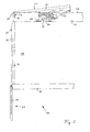
- the lifting wall 13; 13.1; 13.2 can be based on the closed position shown in Figure 3 rotatable about serving as a support and guide element 29, stationary arranged support and guide roller 30 via a in FIG 1 shown intermediate position 45 in a in Figure 2 or Figure 4 shown open position 23, 24 swung up become.
- Link chain 26 with its one end to a receptacle attached. It is understood that instead of a link chain 26 also a rope or the like can be used can. As can be seen in particular from FIG. 5, the Link chain 26 in the closed state of the side wall 12th in a Rurgiaus Principleung 76 of the stanchion 17 and is through Edging profiles 79 of the lifting wall 13 and not closer represented corresponding border profiles of the flap wall 14 covered in the closed state and is thus of not visible on the outside in the closed position.
- link chain 26 With an inner chain part 77 upwards and is at one in the area of the lateral edge of the box roof 15 arranged and about a parallel to the pivot axis 19 rotatable pulley 27, which is designed here as a sprocket is, distracted. From there the link chain runs 26 with its outer chain part 78 along the lifting wall 13, at whose, shown in Figure 3 closed position 22nd lower end 37, the other end of the link chain 26th also attached to a receptacle.
- the lifting wall 13 is supported on an inside constantly at the support and Guide roller 30 from the axis of rotation 47 in the embodiment coincides with the axis of rotation 46 of the guide roller 27 and which is arranged laterally next to the deflection roller 27 ( Figure 6).
- the support and guide roller 30 is with at least one radially outwardly extending circumferential guide collar 81 for lateral guidance of the Lifting wall 13; 13.1, 13.2 provided.
- the distance 28 of the point of attack for the Pulling means 25 on the flap wall 14 of the pivot axis 19th is chosen such that when in its open position 21st pivoted flap wall 14, the lifting wall 13; 13.1, 13.2 completely and without lateral projection in an open position 23, 24 is swung, in which they are the Width of the box body 10 in the roof area 59 laterally not towered over and therefore not when loading and / or unloading of cargo, in particular by stackers, can not be damaged, so that too with the Hubwand connected parts not damaged in this way become.
- handlebar 31; 31.1, 31.2 As another guide element for the lifting wall 13; 13.1, 13.2 is a above the hold 18 extending handlebar 31; 31.1, 31.2 arranged.
- This handlebar 31; 31.1, 31.2 about a first pivot axis 32 and handlebar axis 73.1, 73.2 one fixed at one of its ends 33 in the roof area 59 arranged first joint 34; 34.1, 34.2 freely pivotable hinged and is about a second pivot axis 35 of an arranged at the other end 36 and with the lifting wall thirteenth in the region of its in the closed position 22 upper end 38th connected second joint 41 also hinged pivotally.
- the joints 34; 34.1, 34.2 and 41 are preferred each as a hinge with a parallel to each other arranged rotational axis designed, each perpendicular to a vertical pivot plane of the lifting wall 13; 13.1, 13.2 can be arranged.
- the first, lower hinge 34; 34.1, 34.2 is part of a roof area 59, preferably at a mounting rail 80, during the pivoting movement the handlebar 31 stationary, preferably releasably secured Deflection housing 60, which in the embodiment with two parallel, vertically upwardly extending legs 61.1 and 62.2 is designed (see in particular Figure 6).
- the first pivot axis 32; 73.1, 73.2 of the arranged stationary first joint 34; 34.1, 34.2 and the second Pivot axis 35 of articulated with the lifting wall 13 second hinge 41 of the handlebar 31; 31.1, 31.2 are in one Distance 43 from each other, here about half the height 44 of the lifting wall 13; 13.1, 13.2 corresponds.
- the only rigid handlebar 31 the Lifting wall 44 starting from their example in Figure 3 shown closed position 22 to one in Figure 2 or in 4 opening position shown 23, 24 to pivot, in the lifting wall 13; 13.1, 13.2 completely over the roof 15 and without lateral projection on the vertical escape of the box body 10 can be pivoted upwards.
- the handlebar 31 projects beyond the upper roof edge 42 of the box roof 15 addition, which in the embodiment also for the Lifting wall 13 with regard to their arrangement, design and attachment to the handlebar 31; 31.1, 31.2.
- the intermediate position 45 shown in Figure 1 extends the handlebar 31 so vertically upwards over the top edge of the roof 42 out.
- the inner contour of the outer contour of the profile bar 49 is designed so that the profile bar 49 in the longitudinal direction of the tube axis of the profile tube 50 in the profile tube 50 is displaceable.
- the profile tube 50 and the guided therein Section bar 49 spaced in the longitudinal direction of the handlebar 31 through holes arranged in a row of holes, by one or more locking pins 75 for fixing the Profile bar 49 on the profile tube 50 in the desired Distance length are hin barnsteckbar.
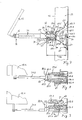
- the lifting wall 13 are in the embodiment several, as power storage 51 serving tension springs 53; 53.1 to 53.4 intended.
- Their respective first end 54.1 engages a first distance 52 from the first pivot axis 32; 73.1, 73.2 of the handlebar 31; 31.1, 31.2 at one with this connected fastening means, here in the form of a fastening bolt on, the or with the handlebar 31; 31.1, 31.2 about the first pivot axis 32; 73.1, 73.2 swiveling when the handlebar 31; 31.1, 31.2 about the pivot axis 32; 73.1, 73.2 is pivoted.
- the respective second end 54.2 the tension springs 53; 53.1 to 53.4 intervenes in a second Distance 57 from the first pivot axis 32; 73.1, 73.2 of the Handlebar 31; 31.1, 31.2 at a spring engagement point 58; 58.1 to 58.5, which is stationary with the roof area 59 connected is.
- the second distance 57 in the shown Embodiment smaller than the first distance 52.
- the Spring engagement points 58; 58.1 to 58.5 are here as swivels or rotating axes designed, in the embodiment for a suspension 63; 63.1, 63.2 for the springs 53.1 to 53.4, whereby the spring travel of the springs advantageous is renewable.
- the suspension 63; 63.1, 63.2 points in Sphere of her one end one in the vertical Pivoting plane of the handlebar 31; Extending 31.1, 31.2 Mounting bolt on, as a fastener for the respective second ends 54.2 of the tension springs 53.1 to 53.4 serves as shown in particular in Figure 7.
- the Suspension 63; 63.1, 63.2 is one parallel to the first Pivot axis 32, 73.1, 73.2 of the handlebar 31; 31.1, 31.2 in the Distance 61 arranged axis of rotation 66 rotatably mounted in the shown embodiment at the middle of here a total of 5 spring points 58.1 to 58.5 rotatable is stored.
- the suspension is 63; 63.1, 63.2 with an elongated profile 64 designed, which is a first attachment point 65.1 for a having first spring 53.1 and a second attachment point 65.2 for a second spring 53.2, wherein the Attachment points here at the transversely to the elongated Profile 64 extended fastening bolts are formed, and wherein the axis of rotation 66 of the suspension 63 between the first spring 53.1 and the second spring 53.2 is arranged.
- the suspension 63; 63.1, 63.2 is in Embodiment as a on both sides of the axis of rotation 66 extending elongate profile 64, so with itself extending from the axis of rotation 66 in opposite directions Profile legs designed so that a favorable Supporting the suspension 63 on both sides of the Rotary axis 66 and on both sides of the elongated profile 64th arranged tension springs 53.1 and 53.2 is possible.
- the sliding part 67 is on the handlebar 31; 31.1, 31.2 along the same slidably arranged.
- the sliding part 67 has a transversely to the handlebar axis 32, 73.1, 73.2 extending Leg 68, which in the embodiment with a along the handlebar 31; 31.1, 31.2 extending internal thread 69 is formed, in the one with matching external thread 71 shaped threaded bolt 70 is screwed, whose protruding from the leg 68 on its other side End at a transverse leg 72 of the handlebar 31st supported (see in particular Figure 6).
- the box structure 10th preferably at its opposite longitudinal end faces each with a two-leaf side wall 12.1 and 12.2 can be provided.
- the side walls are 12.1 and 12.2 preferably of substantially equal parts designed as the side wall 12 according to the figures 1 to 3 as well as 5 to 7, except the handlebar constructions ( Figures 8 and 9).
- a first link 31.1 a first side wall 12.1 to one in the roof area 59 of the Box structure 10 fixedly arranged first link axle 73.1 be pivotally mounted about a rotation axis 74.1
- a second link 31.2 a second side wall 12.2 to a likewise in the roof area 59 of the box body 10 stationary arranged second link shaft 73.2 about an axis of rotation 74.2 may be pivotally mounted, wherein the second link 31.2 in the direction of the axis of rotation 74.1 of the first link 31.1 is arranged offset transversely to the first link 31.1.
- handlebar designs thus differ in the Essentially by different fastening means, here fastening bolts, on which the second ends of the Are mounted springs 53.1 to 53.4, and further by the Location and arrangement of the links 31.1, 31.2 relative to their Swivel axes 73.1 and 73.2, while the springs 53.1 to 53.4, the suspensions 63.1, 63.2 and the deflection housing 60th with their vertically rising legs 62.1 and 62.2 each designed the same.
- the flap wall 14 is preferably manually in the direction of the arrow 82 about its pivot axis 19th panned down.
- the flap wall 14 is preferably manually in the direction of the arrow 82 about its pivot axis 19th panned down.
Landscapes
- Engineering & Computer Science (AREA)
- Mechanical Engineering (AREA)
- Fittings On The Vehicle Exterior For Carrying Loads, And Devices For Holding Or Mounting Articles (AREA)
- Closing Of Containers (AREA)
- Cartons (AREA)
- Buildings Adapted To Withstand Abnormal External Influences (AREA)
- Finger-Pressure Massage (AREA)
- Conveying And Assembling Of Building Elements In Situ (AREA)
- Closing And Opening Devices For Wings, And Checks For Wings (AREA)
- Toys (AREA)
Abstract
Description
- Fig. 1:
- einen Teilquerschnitt eines Kastenaufbaus mit seitlich teilweise geöffneter Ladewand, wobei aus Darstellungsgründen die Zugfedern weggelassen wurden;
- Fig. 2:
- einen Teilquerschnitt eines Kastenaufbaus bei vollständig geöffneter Ladewand;
- Fig. 3:
- einen Teilquerschnitt eines Kastenaufbaus bei vollständig geschlossener Ladewand;
- Fig. 4:
- einen Teilquerschnitt im Dachbereich über die gesamte Breite eines Kastenaufbaus mit beiderseits desselben angeordneten, jeweils vollständig geöffneten Hubwänden, wobei aus Darstellungsgründen die Zugfedern weggelassen wurden;
- Fig. 5:
- einen Teilquerschnitt im Bereich einer vertikalen Runge eines Kastenaufbaus bei geschlossener Hubwand;
- Fig. 6:
- eine dreidimensionale Teildarstellung eines Kastenaufbaus im Dachbereich bei geschlossener Hubwand, wobei aus Darstellungsgründen die Zugfedern weggelassen wurden;
- Fig. 7:
- eine Seitenansicht im Bereich eines Lenkers für eine Hubwand;
- Fig. 8:
- eine gegenüber der Darstellung von Fig. 7 um 90° nach links gedrehte Ansicht im Bereich eines ersten Lenkers für eine erste Hubwand;
- Fig. 9:
- eine der Fig. 8 entsprechende Ansicht im Bereich eines zweiten Lenkers für eine zweite Hubwand.
Claims (20)
- Kastenaufbau (10), insbesondere für Nutzfahrzeuge, mit einem Kastenboden (16), einem Kastendach (15), einem Laderaum (18) und wenigstens einer zweiflügeligen Seitenwand (12; 12.1, 12.2), die eine im Bereich des Kastenbodens (16) angelenkte und um eine Anlenkachse (19) aus ihrer Schließlage (20) in eine Öffnungslage (21) herausschwenkbaren Klappwand (14) aufweist, und mit einer im Dachbereich (59) in eine Öffnungsstellung (23, 24) hochschwenkbaren Hubwand (13; 13.1, 13.2), die mit der Klappwand (14) mit wenigstens einem biegbaren Zugmittel (25) verbunden ist, das um eine im Dachbereich (59) angeordnete Umlenkrolle (27) geschlungen ist und an der Klappwand (14) im Abstand (28) von der Anlenkachse (19) angreift, so dass beim Herabklappen der Klappwand (14) die Hubwand (13; 13.1, 13.2) in eine Öffnungsstellung (23) gelangt, und wobei im Dachbereich (59) ein Stütz- und Führungselement (29) angeordnet ist, an dem die Hubwand (13; 13.1, 13.2) beim Verschwenken von ihrer Schließstellung (22) in ihre Öffnungsstellung (23) und umgekehrt unter gleichzeitiger Verschiebung relativ zu dem Stütz- und Führungselement (29) anliegt, und mit einem sich oberhalb des Laderaums erstreckenden Lenker (31; 31.1, 31.2) für die Hubwand (13; 13.1, 13.2),
dadurch gekennzeichnet, dass der Lenker (31; 31.1, 31.2) um eine erste Schwenkachse (32; 73.1, 73.2) eines an einem seiner Enden (33) im Dachbereich (59) ortsfest angeordneten ersten Gelenks (34; 34.1, 34.2) frei schwenkbar angelenkt ist und um eine zweite Schwenkachse (35) eines an seinem anderen Ende (36) angeordneten und mit der Hubwand (13; 13.1, 13.2) im Bereich ihres in der Schließstellung (22) oberen Endes (38) verbundenen zweiten Gelenks (41) schwenkbar angelenkt ist. - Kastenaufbau nach Anspruch 1, dadurch gekennzeichnet, dass ein einziger Lenker (31; 31.1, 31.2) vorgesehen ist.
- Kastenaufbau nach Anspruch 1 oder 2, dadurch gekennzeichnet, dass die erste Schwenkachse (32; 73.1, 73.2) des ersten Gelenks (34; 34.1, 34.2) und die zweite Schwenkachse (35) des zweiten Gelenks (41) des Lenkers (31; 31.1, 31.2) in einem Abstand (52) voneinander angeordnet sind, der etwa der Hälfte der Höhe (44) der Hubwand (13; 13.1, 13.2) entspricht.
- Kastenaufbau nach einem der Ansprüche 1 bis 3, dadurch gekennzeichnet, dass die Hubwand (13; 13.1, 13.2) und/oder der Lenker (31; 31.1, 31.2) zumindest in einer Zwischenstellung (45) zwischen der Öffnungsstellung (23) und der Schließstellung (22) der Hubwand (13; 13.1, 13.2) über eine obere Dachkante (42) des Kastendaches (15) nach oben hinausragt.
- Kastenaufbau nach einem der Ansprüche 1 bis 4, dadurch gekennzeichnet, dass Mittel (48) zur variablen Einstellung des Abstandes (43) zwischen dem ersten Gelenk (34; 34.1, 34.2) des Lenkers (31; 31.1, 31.2) und dem zweiten Gelenk (41) des Lenkers (31; 31.1, 31.2) vorgesehen sind.
- Kastenaufbau nach einem der Ansprüche 1 bis 5, dadurch gekennzeichnet, dass eine einzige Umlenkrolle (27) für das Zugmittel (25) vorgesehen ist.
- Kastenaufbau nach Anspruch 6, dadurch gekennzeichnet, dass das Stütz- und Führungselement (29) als Stütz- und Führungsrolle (30) ausgebildet ist, die koaxial zu der Umlenkrolle (27) und ortsfest im Bereich einer seitlichen Kante des Kastendaches (15) angeordnet ist.
- Kastenaufbau nach einem der Ansprüche 1 bis 7, dadurch gekennzeichnet, dass das Zugmittel (25) im Bereich des unteren Endes (37) der Hubwand (13; 13.1, 13.2) an dieser angreift.
- Kastenaufbau nach einem der Ansprüche 1 bis 8, dadurch gekennzeichnet, dass die Hubwand (13; 13.1, 13.2) beim Verschwenken von ihrer Schließstellung (22) in ihre Öffnungsstellung (23) und umgekehrt ständig an dem Stütz- und Führungselement (29) anliegt.
- Kastenaufbau nach einem der Ansprüche 1 bis 9, dadurch gekennzeichnet, dass wenigstens ein im Dachbereich (59) angeordneter Kraftspeicher (51) vorgesehen ist, der im Abstand (52) von der ersten Schwenkachse (32; 73.1, 73.2) an dem Lenker (31; 31.1, 31.2) angreift, so dass der Schließvorgang und/oder der Öffnungsvorgang der Hubwand (13; 13.1, 13.2) unterstützt ist.
- Kastenaufbau nach Anspruch 10, dadurch gekennzeichnet, dass es sich bei dem Kraftspeicher (51) um eine Zugfeder (53; 53.1 bis 53.4) handelt, deren erstes Ende (54.1) in einem ersten Abstand (52) von der ersten Schwenkachse (32; 73.1, 73.2) des Lenkers (31; 31.1, 31.2) an einem mit diesem verbundenen Befestigungsmittel (86; 87.1, 87.2) angreift, das mit dem Lenker (31; 31.1, 31.2) um die erste Schwenkachse (32) schwenkbar ist und deren zweites Ende (54.2) in einem gegenüber dem ersten Abstand (52) kleineren zweiten Abstand (57) von der ersten Schwenkachse (32; 73.1, 73.2) des Lenkers (31; 31.1, 31.2) an einer Federangriffsstelle (58; 58.1 bis 58.5) angreift, die ortsfest mit dem Dachbereich (59) verbunden ist.
- Kastenaufbau nach Anspruch 11, dadurch gekennzeichnet, dass die Federangriffsstelle (58; 58.1 bis 58.5) an einem im Dachbereich (59) ortsfest angeordneten Umlenkgehäuse (60) in einem vertikalen Abstand (61) oberhalb der an dem Umlenkgehäuse (60) gelagerten ersten Schwenkachse (32; 73.1, 73.2) angeordnet ist.
- Kastenaufbau nach Anspruch 11 oder 12, dadurch gekennzeichnet, dass die Federangriffsstelle (58; 58.1 bis 58.5) mit einem Gelenk für eine um eine Drehachse (66) drehbare Aufhängung (63; 63.1, 63.2) für die Feder (53; 53.1 bis 53.4) ausgebildet ist, an der das zweite Ende (54.2) der Zugfeder (53; 53.1 bis 53.4) befestigt ist.
- Kastenaufbau nach Anspruch 12 oder 13, dadurch gekennzeichnet, dass zum Ausgleich von unterschiedlichen Gewichtsverhältnissen der Hubwand (13; 13.1, 13.2) und der Klappwand (14) mehrere Federangriffsstellen (58; 58.1 bis 58.5) vorgesehen sind, an denen die Zugfeder (53; 53.1 bis 53.4) wahlweise festlegbar ist, wobei wenigstens eine Federangriffsstelle (58.1 bis 58.5) quer zur ersten Schwenkachse (32) in Horizontalrichtung gegenüber einer benachbarten Federangriffsstelle versetzt angeordnet ist.
- Kastenaufbau nach Anspruch 13 oder 14, dadurch gekennzeichnet, dass die Aufhängung (63; 63.1, 63.2) mit einem langgestreckten Profil (64) gestaltet ist, das eine erste Befestigungsstelle (65.1) für eine erste Feder (53.1) aufweist und das eine zweite Befestigungsstelle (65.2) für eine zweite Feder (53.2) aufweist, wobei die Drehachse (66) der Aufhängung (63; 63.1, 63.2) zwischen der ersten Feder (53.1) und der zweiten Feder (53.2) angeordnet ist.
- Kastenaufbau nach einem der Ansprüche 13 bis 15, dadurch gekennzeichnet, dass die Aufhängung (63; 63.1, 63.2) als ein sich beiderseits der Drehachse (66) erstreckendes Profil (64) gestaltet ist.
- Kastenaufbau nach einem der Ansprüche 1 bis 16, dadurch gekennzeichnet, dass an dem Lenker (31; 31.1, 31.2) ein Befestigungskörper (85) befestigt ist, an dem die Feder (53; 53.1 bis 53.4) angreift und der dazu bestimmt ist, unterschiedliche Federspannungen einstellen zu können.
- Kastenaufbau nach Anspruch 17, dadurch gekennzeichnet, dass der Befestigungskörper (85) dazu bestimmt ist, eine stufenlose Einstellung der Federspannung zu ermöglichen.
- Kastenaufbau nach Anspruch 17 oder 18, dadurch gekennzeichnet, dass der Befestigungskörper (85) als ein sich an dem Lenker (31; 31.1, 31.2) abstützender und längs desselben verschiebbarer Schiebeteil (67) gestaltet ist, an dem ein Schenkel (68) mit einem sich längs des Lenkers (31; 31.1, 31.2) erstreckenden Innengewinde (69) befestigt ist, in dem ein Gewindebolzen (70) mit Außengewinde (71) eingeschraubt ist, dessen Ende sich an einem Querschenkel (72) des Lenkers (31; 31.1, 31.2) abstützt.
- Kastenaufbau nach einem der Ansprüche 1 bis 19, dadurch gekennzeichnet, dass er an seinen beiden seitlichen Stirnseiten jeweils eine zweiflügelige Seitenwand (12.1, 12.2) nach einem der Ansprüche 1 bis 19 aufweist, wobei ein erster Lenker (31.1) einer ersten Seitenwand (12.1) um eine im Dachbereich (59) des Kastenaufbaus (10) ortsfest angeordnete erste Lenkerachse (73.1) schwenkbar gelagert ist, und wobei ein zweiter Lenker (31.2) einer zweiten Seitenwand (12.2) um eine im Dachbereich (59) des Kastenaufbaus (10) ortsfest angeordnete zweite Lenkerachse (73.2) schwenkbar gelagert ist, wobei der zweite Lenker (31.2) in Richtung der Drehachse (74.1) des ersten Lenkers quer zu dem ersten Lenker (31.1) versetzt angeordnet ist, so dass sich die beiden Lenker (31.1, 31.2) bei vollständig über das Kastendach (15) hochgeschwenkten und sich im Bereich ihrer in ihren Schließstellungen oberen Enden (38.1, 38.2) überlappenden Hubwänden (13.1, 13.2) kreuzen.
Priority Applications (2)
| Application Number | Priority Date | Filing Date | Title |
|---|---|---|---|
| DE202004021073U DE202004021073U1 (de) | 2003-09-19 | 2004-08-07 | Kastenaufbau |
| PL04018787T PL1516763T3 (pl) | 2003-09-19 | 2004-08-07 | Nadwozie skrzyniowe |
Applications Claiming Priority (2)
| Application Number | Priority Date | Filing Date | Title |
|---|---|---|---|
| DE10343915 | 2003-09-19 | ||
| DE10343915A DE10343915B4 (de) | 2003-09-19 | 2003-09-19 | Kastenaufbau |
Publications (3)
| Publication Number | Publication Date |
|---|---|
| EP1516763A2 true EP1516763A2 (de) | 2005-03-23 |
| EP1516763A3 EP1516763A3 (de) | 2007-01-17 |
| EP1516763B1 EP1516763B1 (de) | 2009-11-04 |
Family
ID=34177894
Family Applications (1)
| Application Number | Title | Priority Date | Filing Date |
|---|---|---|---|
| EP04018787A Expired - Lifetime EP1516763B1 (de) | 2003-09-19 | 2004-08-07 | Kastenaufbau |
Country Status (4)
| Country | Link |
|---|---|
| EP (1) | EP1516763B1 (de) |
| AT (1) | ATE447502T1 (de) |
| DE (3) | DE20321820U1 (de) |
| PL (1) | PL1516763T3 (de) |
Cited By (2)
| Publication number | Priority date | Publication date | Assignee | Title |
|---|---|---|---|---|
| EP1920958A1 (de) * | 2006-11-07 | 2008-05-14 | Orten Karlsdorf-Neuthard GmbH & Co. KG | Vorrichtung zum Überführen einer Wand eines Transportbehälters zwischen einer Schließstellung und einer Offenstellung und Transportbehälter mit einer solchen Vorrichtung |
| WO2010115226A1 (de) * | 2009-04-09 | 2010-10-14 | Strasser Johann Sen | Vorrichtung zum überführen einer wand eines transportbehälters und transportbehälter damit |
Family Cites Families (12)
| Publication number | Priority date | Publication date | Assignee | Title |
|---|---|---|---|---|
| DE7707180U1 (de) | 1977-03-09 | 1977-08-11 | Heinz Boese Kg, 5779 Reiste | Aufbau für einen Lastkraftwagen oder Anhänger mit Ladebordwänden |
| DE2813593C2 (de) * | 1978-03-30 | 1982-02-11 | Franz 5778 Meschede Ewers | Seitenwand für Kastenaufbauten von Lastkraftwagen |
| DE2931111C2 (de) | 1979-07-31 | 1984-04-05 | Diamoil S.A., 1207 Genève | Fahrzeugaufbau mit in horizontaler Richtung unterteilten Seitenwänden |
| DE3121690A1 (de) * | 1981-06-01 | 1982-12-16 | F.X. Kögel GmbH & Co Fahrzeugwerke, 7900 Ulm | "geteilte ladebordwand" |
| DE3219505A1 (de) | 1982-05-25 | 1983-12-01 | F.X. Kögel GmbH & Co Fahrzeugwerke, 7900 Ulm | Ladebordwand fuer gedeckte kraftfahrzeug-aufbauten |
| EP0116722B1 (de) | 1983-01-26 | 1987-04-15 | TREFA - Jürgen Nichts Karosserie- und Fahrzeugtechnik GmbH & Co KG | Vorrichtung zum gleichzeitigen Öffnen bzw. Schliessen eines unteren und eines oberen Wandteiles einer Bordwand |
| DE3525628A1 (de) | 1985-07-18 | 1987-01-22 | Gross Aluminium Gmbh | Klappwand, insbesondere fuer fahrzeugaufbauten |
| DE4033691C2 (de) | 1990-10-23 | 1999-03-04 | Georg Maierbacher | Seitenwandanordnung für gedeckte Kastenaufbauten |
| DE4427518C1 (de) * | 1994-08-03 | 1996-01-18 | Georg Maierbacher | Fahrzeugaufbau, insbesondere für Lastkraftwagen und Anhänger, mit einer öffenbaren Seitenwand |
| DK0751022T3 (da) | 1995-06-28 | 1999-01-18 | Keppler Gmbh Fahrzeugbau | Kassekonstruktion |
| WO1997034793A1 (de) * | 1996-03-21 | 1997-09-25 | Johann Strasser | Seitenwand für den aufbau eines fahrzeuges |
| DE19839839B4 (de) | 1998-09-02 | 2008-09-04 | Georg Ewers | Seitenwand eines Fahrzeugs oder Anhängers |
-
2003
- 2003-09-19 DE DE20321820U patent/DE20321820U1/de not_active Expired - Lifetime
- 2003-09-19 DE DE10343915A patent/DE10343915B4/de not_active Expired - Fee Related
-
2004
- 2004-08-07 AT AT04018787T patent/ATE447502T1/de active
- 2004-08-07 DE DE502004010316T patent/DE502004010316D1/de not_active Expired - Lifetime
- 2004-08-07 PL PL04018787T patent/PL1516763T3/pl unknown
- 2004-08-07 EP EP04018787A patent/EP1516763B1/de not_active Expired - Lifetime
Cited By (2)
| Publication number | Priority date | Publication date | Assignee | Title |
|---|---|---|---|---|
| EP1920958A1 (de) * | 2006-11-07 | 2008-05-14 | Orten Karlsdorf-Neuthard GmbH & Co. KG | Vorrichtung zum Überführen einer Wand eines Transportbehälters zwischen einer Schließstellung und einer Offenstellung und Transportbehälter mit einer solchen Vorrichtung |
| WO2010115226A1 (de) * | 2009-04-09 | 2010-10-14 | Strasser Johann Sen | Vorrichtung zum überführen einer wand eines transportbehälters und transportbehälter damit |
Also Published As
| Publication number | Publication date |
|---|---|
| DE10343915B4 (de) | 2010-11-25 |
| PL1516763T3 (pl) | 2010-04-30 |
| DE10343915A1 (de) | 2005-05-04 |
| DE502004010316D1 (de) | 2009-12-17 |
| ATE447502T1 (de) | 2009-11-15 |
| DE20321820U1 (de) | 2010-10-28 |
| EP1516763B1 (de) | 2009-11-04 |
| EP1516763A3 (de) | 2007-01-17 |
Similar Documents
| Publication | Publication Date | Title |
|---|---|---|
| DE102006053523B3 (de) | Vorrichtung zum Überführen einer Wand eines Transportbehälters zwischen einer Schliessstellung und einer Offenstellung und Transportbehälter | |
| EP1354790B1 (de) | Klapprunge mit Riegeleinrichtung | |
| CH645580A5 (de) | Lastkraftwagen mit einer ladepritsche und einem aufbau. | |
| EP1516763B1 (de) | Kastenaufbau | |
| EP2010736A1 (de) | Abstellvorrichtung für kraftfahrzeuge | |
| DE2817759A1 (de) | Gelenkarmmarkise | |
| DE4033691C2 (de) | Seitenwandanordnung für gedeckte Kastenaufbauten | |
| WO2010086318A1 (de) | Beschlaganordnung für lichtkuppel | |
| EP0785330B1 (de) | Heckklappenanlenkung für Kraftfahrzeuge | |
| DE102014013787B4 (de) | Verdeckgestell für eine zusammenschiebbare Plane | |
| DE2134083A1 (de) | Waagerecht zusammenklappbarer Turmkran | |
| AT509550B1 (de) | Vorrichtung zum überführen einer wand eines transportbehälters | |
| DE202004021073U1 (de) | Kastenaufbau | |
| DE102014013788B4 (de) | Verdeckgestell für eine zusammenschiebbare Plane | |
| DE10235922B4 (de) | Verfahren zur Veränderung der Fläche des Lastraumes einer Arbeitsmaschine | |
| DE60300274T2 (de) | Fahrzeug mit Heckklappe mit zwei Offenstellungen | |
| DE102005016158B3 (de) | Verdeckgestell für einen Planenaufbau | |
| DE102014013789B4 (de) | Verdeckgestell für eine zusammenschiebbare Plane | |
| DE102007047577B4 (de) | Vorrichtung zum gegenläufigen Verschwenken von wenigstens zwei Dachelementen eines Satteldaches und Satteldach mit dieser Vorrichtung | |
| WO2015128468A1 (de) | Faltplatte | |
| DE212023000231U1 (de) | Gerät zur Handhabung von Lasten | |
| AT507244B1 (de) | Fahrzeugaufbau | |
| DE3346858C2 (de) | Fahrzeug zum Transportieren und Aufstellen von Raumzellen, insbesondere Fertiggaragen | |
| DE3437341A1 (de) | Faltbare trittleiter | |
| EP1809844A1 (de) | Drehtorantriebsvorrichtung, beschlag hierfür und damit versehenes drehtor |
Legal Events
| Date | Code | Title | Description |
|---|---|---|---|
| PUAI | Public reference made under article 153(3) epc to a published international application that has entered the european phase |
Free format text: ORIGINAL CODE: 0009012 |
|
| AK | Designated contracting states |
Kind code of ref document: A2 Designated state(s): AT BE BG CH CY CZ DE DK EE ES FI FR GB GR HU IE IT LI LU MC NL PL PT RO SE SI SK TR |
|
| AX | Request for extension of the european patent |
Extension state: AL HR LT LV MK |
|
| 19U | Interruption of proceedings before grant |
Effective date: 20050502 |
|
| 19W | Proceedings resumed before grant after interruption of proceedings |
Effective date: 20051201 |
|
| RAP1 | Party data changed (applicant data changed or rights of an application transferred) |
Owner name: TSE TRAILER-SYSTEM-ENGINEERING GMBH & CO. KG |
|
| PUAL | Search report despatched |
Free format text: ORIGINAL CODE: 0009013 |
|
| AK | Designated contracting states |
Kind code of ref document: A3 Designated state(s): AT BE BG CH CY CZ DE DK EE ES FI FR GB GR HU IE IT LI LU MC NL PL PT RO SE SI SK TR |
|
| AX | Request for extension of the european patent |
Extension state: AL HR LT LV MK |
|
| 17P | Request for examination filed |
Effective date: 20070717 |
|
| AKX | Designation fees paid |
Designated state(s): AT BE BG CH CY CZ DE DK EE ES FI FR GB GR HU IE IT LI LU MC NL PL PT RO SE SI SK TR |
|
| 17Q | First examination report despatched |
Effective date: 20080108 |
|
| GRAP | Despatch of communication of intention to grant a patent |
Free format text: ORIGINAL CODE: EPIDOSNIGR1 |
|
| RAP1 | Party data changed (applicant data changed or rights of an application transferred) |
Owner name: ORTEN, ROBERT ERICH |
|
| GRAS | Grant fee paid |
Free format text: ORIGINAL CODE: EPIDOSNIGR3 |
|
| GRAA | (expected) grant |
Free format text: ORIGINAL CODE: 0009210 |
|
| AK | Designated contracting states |
Kind code of ref document: B1 Designated state(s): AT BE BG CH CY CZ DE DK EE ES FI FR GB GR HU IE IT LI LU MC NL PL PT RO SE SI SK TR |
|
| REG | Reference to a national code |
Ref country code: GB Ref legal event code: FG4D Free format text: NOT ENGLISH |
|
| REG | Reference to a national code |
Ref country code: CH Ref legal event code: EP |
|
| REG | Reference to a national code |
Ref country code: IE Ref legal event code: FG4D |
|
| REF | Corresponds to: |
Ref document number: 502004010316 Country of ref document: DE Date of ref document: 20091217 Kind code of ref document: P |
|
| REG | Reference to a national code |
Ref country code: CH Ref legal event code: NV Representative=s name: TROESCH SCHEIDEGGER WERNER AG |
|
| PG25 | Lapsed in a contracting state [announced via postgrant information from national office to epo] |
Ref country code: FI Free format text: LAPSE BECAUSE OF FAILURE TO SUBMIT A TRANSLATION OF THE DESCRIPTION OR TO PAY THE FEE WITHIN THE PRESCRIBED TIME-LIMIT Effective date: 20091104 Ref country code: ES Free format text: LAPSE BECAUSE OF FAILURE TO SUBMIT A TRANSLATION OF THE DESCRIPTION OR TO PAY THE FEE WITHIN THE PRESCRIBED TIME-LIMIT Effective date: 20100215 Ref country code: PT Free format text: LAPSE BECAUSE OF FAILURE TO SUBMIT A TRANSLATION OF THE DESCRIPTION OR TO PAY THE FEE WITHIN THE PRESCRIBED TIME-LIMIT Effective date: 20100304 Ref country code: SE Free format text: LAPSE BECAUSE OF FAILURE TO SUBMIT A TRANSLATION OF THE DESCRIPTION OR TO PAY THE FEE WITHIN THE PRESCRIBED TIME-LIMIT Effective date: 20091104 |
|
| REG | Reference to a national code |
Ref country code: PL Ref legal event code: T3 |
|
| REG | Reference to a national code |
Ref country code: IE Ref legal event code: FD4D |
|
| PG25 | Lapsed in a contracting state [announced via postgrant information from national office to epo] |
Ref country code: CY Free format text: LAPSE BECAUSE OF FAILURE TO SUBMIT A TRANSLATION OF THE DESCRIPTION OR TO PAY THE FEE WITHIN THE PRESCRIBED TIME-LIMIT Effective date: 20091104 Ref country code: SI Free format text: LAPSE BECAUSE OF FAILURE TO SUBMIT A TRANSLATION OF THE DESCRIPTION OR TO PAY THE FEE WITHIN THE PRESCRIBED TIME-LIMIT Effective date: 20091104 |
|
| PG25 | Lapsed in a contracting state [announced via postgrant information from national office to epo] |
Ref country code: IE Free format text: LAPSE BECAUSE OF FAILURE TO SUBMIT A TRANSLATION OF THE DESCRIPTION OR TO PAY THE FEE WITHIN THE PRESCRIBED TIME-LIMIT Effective date: 20091104 Ref country code: BG Free format text: LAPSE BECAUSE OF FAILURE TO SUBMIT A TRANSLATION OF THE DESCRIPTION OR TO PAY THE FEE WITHIN THE PRESCRIBED TIME-LIMIT Effective date: 20100204 Ref country code: DK Free format text: LAPSE BECAUSE OF FAILURE TO SUBMIT A TRANSLATION OF THE DESCRIPTION OR TO PAY THE FEE WITHIN THE PRESCRIBED TIME-LIMIT Effective date: 20091104 Ref country code: EE Free format text: LAPSE BECAUSE OF FAILURE TO SUBMIT A TRANSLATION OF THE DESCRIPTION OR TO PAY THE FEE WITHIN THE PRESCRIBED TIME-LIMIT Effective date: 20091104 Ref country code: RO Free format text: LAPSE BECAUSE OF FAILURE TO SUBMIT A TRANSLATION OF THE DESCRIPTION OR TO PAY THE FEE WITHIN THE PRESCRIBED TIME-LIMIT Effective date: 20091104 |
|
| PG25 | Lapsed in a contracting state [announced via postgrant information from national office to epo] |
Ref country code: SK Free format text: LAPSE BECAUSE OF FAILURE TO SUBMIT A TRANSLATION OF THE DESCRIPTION OR TO PAY THE FEE WITHIN THE PRESCRIBED TIME-LIMIT Effective date: 20091104 |
|
| PLBE | No opposition filed within time limit |
Free format text: ORIGINAL CODE: 0009261 |
|
| STAA | Information on the status of an ep patent application or granted ep patent |
Free format text: STATUS: NO OPPOSITION FILED WITHIN TIME LIMIT |
|
| 26N | No opposition filed |
Effective date: 20100805 |
|
| PG25 | Lapsed in a contracting state [announced via postgrant information from national office to epo] |
Ref country code: GR Free format text: LAPSE BECAUSE OF FAILURE TO SUBMIT A TRANSLATION OF THE DESCRIPTION OR TO PAY THE FEE WITHIN THE PRESCRIBED TIME-LIMIT Effective date: 20100205 |
|
| PGFP | Annual fee paid to national office [announced via postgrant information from national office to epo] |
Ref country code: CZ Payment date: 20100930 Year of fee payment: 7 |
|
| PG25 | Lapsed in a contracting state [announced via postgrant information from national office to epo] |
Ref country code: IT Free format text: LAPSE BECAUSE OF FAILURE TO SUBMIT A TRANSLATION OF THE DESCRIPTION OR TO PAY THE FEE WITHIN THE PRESCRIBED TIME-LIMIT Effective date: 20091104 Ref country code: MC Free format text: LAPSE BECAUSE OF NON-PAYMENT OF DUE FEES Effective date: 20100831 |
|
| PGFP | Annual fee paid to national office [announced via postgrant information from national office to epo] |
Ref country code: BE Payment date: 20101011 Year of fee payment: 7 |
|
| GBPC | Gb: european patent ceased through non-payment of renewal fee |
Effective date: 20100807 |
|
| REG | Reference to a national code |
Ref country code: FR Ref legal event code: ST Effective date: 20110502 |
|
| PG25 | Lapsed in a contracting state [announced via postgrant information from national office to epo] |
Ref country code: FR Free format text: LAPSE BECAUSE OF NON-PAYMENT OF DUE FEES Effective date: 20100831 |
|
| PG25 | Lapsed in a contracting state [announced via postgrant information from national office to epo] |
Ref country code: GB Free format text: LAPSE BECAUSE OF NON-PAYMENT OF DUE FEES Effective date: 20100807 |
|
| BERE | Be: lapsed |
Owner name: ORTEN, ROBERT ERICH Effective date: 20110831 |
|
| PG25 | Lapsed in a contracting state [announced via postgrant information from national office to epo] |
Ref country code: CZ Free format text: LAPSE BECAUSE OF NON-PAYMENT OF DUE FEES Effective date: 20110807 |
|
| PG25 | Lapsed in a contracting state [announced via postgrant information from national office to epo] |
Ref country code: BE Free format text: LAPSE BECAUSE OF NON-PAYMENT OF DUE FEES Effective date: 20110831 |
|
| PG25 | Lapsed in a contracting state [announced via postgrant information from national office to epo] |
Ref country code: HU Free format text: LAPSE BECAUSE OF FAILURE TO SUBMIT A TRANSLATION OF THE DESCRIPTION OR TO PAY THE FEE WITHIN THE PRESCRIBED TIME-LIMIT Effective date: 20100505 |
|
| PGFP | Annual fee paid to national office [announced via postgrant information from national office to epo] |
Ref country code: LU Payment date: 20120824 Year of fee payment: 9 |
|
| PG25 | Lapsed in a contracting state [announced via postgrant information from national office to epo] |
Ref country code: TR Free format text: LAPSE BECAUSE OF FAILURE TO SUBMIT A TRANSLATION OF THE DESCRIPTION OR TO PAY THE FEE WITHIN THE PRESCRIBED TIME-LIMIT Effective date: 20091104 |
|
| PGFP | Annual fee paid to national office [announced via postgrant information from national office to epo] |
Ref country code: NL Payment date: 20120824 Year of fee payment: 9 |
|
| REG | Reference to a national code |
Ref country code: NL Ref legal event code: V1 Effective date: 20140301 |
|
| PG25 | Lapsed in a contracting state [announced via postgrant information from national office to epo] |
Ref country code: NL Free format text: LAPSE BECAUSE OF NON-PAYMENT OF DUE FEES Effective date: 20140301 |
|
| PG25 | Lapsed in a contracting state [announced via postgrant information from national office to epo] |
Ref country code: LU Free format text: LAPSE BECAUSE OF NON-PAYMENT OF DUE FEES Effective date: 20130807 |
|
| PGFP | Annual fee paid to national office [announced via postgrant information from national office to epo] |
Ref country code: PL Payment date: 20150807 Year of fee payment: 12 |
|
| PGFP | Annual fee paid to national office [announced via postgrant information from national office to epo] |
Ref country code: CH Payment date: 20160824 Year of fee payment: 13 |
|
| PGFP | Annual fee paid to national office [announced via postgrant information from national office to epo] |
Ref country code: DE Payment date: 20170921 Year of fee payment: 14 |
|
| PGFP | Annual fee paid to national office [announced via postgrant information from national office to epo] |
Ref country code: AT Payment date: 20170830 Year of fee payment: 14 |
|
| PG25 | Lapsed in a contracting state [announced via postgrant information from national office to epo] |
Ref country code: PL Free format text: LAPSE BECAUSE OF NON-PAYMENT OF DUE FEES Effective date: 20160807 |
|
| REG | Reference to a national code |
Ref country code: CH Ref legal event code: PL |
|
| PG25 | Lapsed in a contracting state [announced via postgrant information from national office to epo] |
Ref country code: LI Free format text: LAPSE BECAUSE OF NON-PAYMENT OF DUE FEES Effective date: 20170831 Ref country code: CH Free format text: LAPSE BECAUSE OF NON-PAYMENT OF DUE FEES Effective date: 20170831 |
|
| REG | Reference to a national code |
Ref country code: DE Ref legal event code: R119 Ref document number: 502004010316 Country of ref document: DE |
|
| REG | Reference to a national code |
Ref country code: AT Ref legal event code: MM01 Ref document number: 447502 Country of ref document: AT Kind code of ref document: T Effective date: 20180807 |
|
| PG25 | Lapsed in a contracting state [announced via postgrant information from national office to epo] |
Ref country code: AT Free format text: LAPSE BECAUSE OF NON-PAYMENT OF DUE FEES Effective date: 20180807 |
|
| PG25 | Lapsed in a contracting state [announced via postgrant information from national office to epo] |
Ref country code: DE Free format text: LAPSE BECAUSE OF NON-PAYMENT OF DUE FEES Effective date: 20190301 |