EP1516654A1 - Informationsprozessor mit eingabesystem unter verwendung eines stroboskops - Google Patents
Informationsprozessor mit eingabesystem unter verwendung eines stroboskops Download PDFInfo
- Publication number
- EP1516654A1 EP1516654A1 EP03733531A EP03733531A EP1516654A1 EP 1516654 A1 EP1516654 A1 EP 1516654A1 EP 03733531 A EP03733531 A EP 03733531A EP 03733531 A EP03733531 A EP 03733531A EP 1516654 A1 EP1516654 A1 EP 1516654A1
- Authority
- EP
- European Patent Office
- Prior art keywords
- light
- information processing
- emission
- processing apparatus
- game
- Prior art date
- Legal status (The legal status is an assumption and is not a legal conclusion. Google has not performed a legal analysis and makes no representation as to the accuracy of the status listed.)
- Withdrawn
Links
Images
















Classifications
-
- A63F13/10—
-
- A—HUMAN NECESSITIES
- A63—SPORTS; GAMES; AMUSEMENTS
- A63F—CARD, BOARD, OR ROULETTE GAMES; INDOOR GAMES USING SMALL MOVING PLAYING BODIES; VIDEO GAMES; GAMES NOT OTHERWISE PROVIDED FOR
- A63F13/00—Video games, i.e. games using an electronically generated display having two or more dimensions
- A63F13/25—Output arrangements for video game devices
- A63F13/28—Output arrangements for video game devices responding to control signals received from the game device for affecting ambient conditions, e.g. for vibrating players' seats, activating scent dispensers or affecting temperature or light
-
- A—HUMAN NECESSITIES
- A63—SPORTS; GAMES; AMUSEMENTS
- A63F—CARD, BOARD, OR ROULETTE GAMES; INDOOR GAMES USING SMALL MOVING PLAYING BODIES; VIDEO GAMES; GAMES NOT OTHERWISE PROVIDED FOR
- A63F13/00—Video games, i.e. games using an electronically generated display having two or more dimensions
- A63F13/20—Input arrangements for video game devices
- A63F13/21—Input arrangements for video game devices characterised by their sensors, purposes or types
- A63F13/213—Input arrangements for video game devices characterised by their sensors, purposes or types comprising photodetecting means, e.g. cameras, photodiodes or infrared cells
-
- A—HUMAN NECESSITIES
- A63—SPORTS; GAMES; AMUSEMENTS
- A63F—CARD, BOARD, OR ROULETTE GAMES; INDOOR GAMES USING SMALL MOVING PLAYING BODIES; VIDEO GAMES; GAMES NOT OTHERWISE PROVIDED FOR
- A63F13/00—Video games, i.e. games using an electronically generated display having two or more dimensions
- A63F13/45—Controlling the progress of the video game
-
- A—HUMAN NECESSITIES
- A63—SPORTS; GAMES; AMUSEMENTS
- A63F—CARD, BOARD, OR ROULETTE GAMES; INDOOR GAMES USING SMALL MOVING PLAYING BODIES; VIDEO GAMES; GAMES NOT OTHERWISE PROVIDED FOR
- A63F13/00—Video games, i.e. games using an electronically generated display having two or more dimensions
- A63F13/80—Special adaptations for executing a specific game genre or game mode
- A63F13/812—Ball games, e.g. soccer or baseball
-
- G—PHYSICS
- G06—COMPUTING OR CALCULATING; COUNTING
- G06T—IMAGE DATA PROCESSING OR GENERATION, IN GENERAL
- G06T7/00—Image analysis
- G06T7/20—Analysis of motion
-
- G—PHYSICS
- G06—COMPUTING OR CALCULATING; COUNTING
- G06T—IMAGE DATA PROCESSING OR GENERATION, IN GENERAL
- G06T7/00—Image analysis
- G06T7/20—Analysis of motion
- G06T7/254—Analysis of motion involving subtraction of images
-
- A—HUMAN NECESSITIES
- A63—SPORTS; GAMES; AMUSEMENTS
- A63F—CARD, BOARD, OR ROULETTE GAMES; INDOOR GAMES USING SMALL MOVING PLAYING BODIES; VIDEO GAMES; GAMES NOT OTHERWISE PROVIDED FOR
- A63F2300/00—Features of games using an electronically generated display having two or more dimensions, e.g. on a television screen, showing representations related to the game
- A63F2300/10—Features of games using an electronically generated display having two or more dimensions, e.g. on a television screen, showing representations related to the game characterized by input arrangements for converting player-generated signals into game device control signals
- A63F2300/1012—Features of games using an electronically generated display having two or more dimensions, e.g. on a television screen, showing representations related to the game characterized by input arrangements for converting player-generated signals into game device control signals involving biosensors worn by the player, e.g. for measuring heart beat, limb activity
-
- A—HUMAN NECESSITIES
- A63—SPORTS; GAMES; AMUSEMENTS
- A63F—CARD, BOARD, OR ROULETTE GAMES; INDOOR GAMES USING SMALL MOVING PLAYING BODIES; VIDEO GAMES; GAMES NOT OTHERWISE PROVIDED FOR
- A63F2300/00—Features of games using an electronically generated display having two or more dimensions, e.g. on a television screen, showing representations related to the game
- A63F2300/10—Features of games using an electronically generated display having two or more dimensions, e.g. on a television screen, showing representations related to the game characterized by input arrangements for converting player-generated signals into game device control signals
- A63F2300/1087—Features of games using an electronically generated display having two or more dimensions, e.g. on a television screen, showing representations related to the game characterized by input arrangements for converting player-generated signals into game device control signals comprising photodetecting means, e.g. a camera
-
- A—HUMAN NECESSITIES
- A63—SPORTS; GAMES; AMUSEMENTS
- A63F—CARD, BOARD, OR ROULETTE GAMES; INDOOR GAMES USING SMALL MOVING PLAYING BODIES; VIDEO GAMES; GAMES NOT OTHERWISE PROVIDED FOR
- A63F2300/00—Features of games using an electronically generated display having two or more dimensions, e.g. on a television screen, showing representations related to the game
- A63F2300/80—Features of games using an electronically generated display having two or more dimensions, e.g. on a television screen, showing representations related to the game specially adapted for executing a specific type of game
- A63F2300/8011—Ball
-
- G—PHYSICS
- G06—COMPUTING OR CALCULATING; COUNTING
- G06T—IMAGE DATA PROCESSING OR GENERATION, IN GENERAL
- G06T2207/00—Indexing scheme for image analysis or image enhancement
- G06T2207/30—Subject of image; Context of image processing
- G06T2207/30241—Trajectory
Definitions
- Patent Literature 3 discloses that an object is extracted from an imaged image signal to obtain the position of the object, and the position information is used as an input of game apparatuses or computers.
- this method works well in a specific use environment, but it is very difficult to obtain accurate position information in a room at a general home where game machines are used. This is because all of the illuminations in the room, windows, objects in various colors, and moving objects except for the game player exert an influence as noise and disturbance on the detection accuracy.
- a high-speed processor is necessary, and this is unrealistic for the information processing apparatus with restricted processing ability and at low costs.
- the present invention relates to an information processing apparatus provided with an input system utilizing a stroboscope, and comprises a stroboscope; an imaging means for imaging an object at a light-emission and at a non-light-emission of the stroboscope to output an image signal at light-emission and an image signal at non-light emission; a first means for calculating a part or all of information of a position, a size, a velocity, an acceleration, a moving path pattern of the object on the basis of differences between the plurality of image signals at light-emission and the plurality of image signals at non-light emission; and a second means for performing information processing on the basis of the information calculated by the first means.
- the above-described first means may include a determination means for determining whether or not the information is coincident with a predetermined condition.
- the first means includes a valid input detecting means for detecting only valid information out of the information on the basis of the determination result by the determination means, and transmitting to the second means as the valid information being performed.
- the analysis by the above-described analyzing means is for extracting predetermined two points within the object, and the calculation of the angle by the angle calculating means is for calculating an angle between a line segment between predetermined two points and a predetermined coordinate axis.
- a time interval of the light-emission of the stroboscope is freely configurable.
- the object includes a reflective body.
- the stroboscope includes a light source for outputting a light having a specific wavelength range, and the imaging means is made to respond to only the specific wavelength range.
- Each of the first means and the second means described above is process to be processed by a single or a plurality of processors.
- a man-machine interface system provided with an input system by utilizing a stroboscope comprises a stroboscope; an imaging means for outputting an image signal at a light-emission and an image signal at a non-light emission by imaging an object at a light-emission of the stroboscope and at a non-light-emission; a first means for calculating a part or all of information of a position, a size, a velocity, an acceleration, a moving path pattern on the basis of differences between the plurality of image signals at a light-emission and a plurality of image signals at a non-light emission; and a second means for performing image processing on the basis of the information calculated by the first means.
- the object (14, 94, 112) is brightly irradiated to heighten a contrast between the object and things except for the object as an imaging result, and therefore, it becomes easy to detect the object.
- the processing for calculating the position, the size, the velocity, the acceleration, the moving path pattern of the object can be utilized without being changed.
- the determination means determines whether or not the position, the size, the velocity, the acceleration, the moving path pattern of the object are coincident with the predetermined condition, and in the information processing at the application side, with reference to the determination result, if the information is not coincident with the predetermined condition, the calculated information is not received, capable of performing simple application processing.
- the valid input detecting means (52, Figure 22, Figure 25, Figure 33) included in the first means makes a choice of the information on the basis of the determination result by the determination means, and transmits only the valid input from the user to the information processing at the application side. Therefore, it becomes possible to perform simple application processing.
- the object includes the reflective body (50, 50A, 100, 116), a contrast between the object and other images are further enhanced, capable of improving accuracy of the detection with an inexpensive configuration.
- the stroboscope includes the light source (the infrared-LED 42, for example) outputting the light having the specific wavelength range, and the imaging means responds only to the specific wavelength range by utilizing the infrared filter. Therefore, rendering the light having the wavelength that the moving light source and blinking light source (fluorescent lamp, etc.) except for the object to be detected do not have the light source of the stroboscope, it is possible to remove the noise light sources.
- the light source the infrared-LED 42, for example
- each of the first means and the second means is a process to be processed by a single or a plurality of processors (processors for processing 52 and/or 63).
- processors processors for processing 52 and/or 63.
- the first means and the second means are rendered processes to be processed as software of the processor, capable of establishing a system with low prices and with high flexibility. It is noted that it is further desirable that the processes of both of the first means and the second means are executed by a single processor.
- the image processing performed by the second means is an entertainment process such as a game, etc.
- man-machine interface for a personal computer, a workstation, game equipment, educational equipment, medical equipment, etc., it is possible to establish the input system with low prices and with high degree of precision.
- the information such as the position, the size, the velocity, the acceleration, the moving path pattern of the object can be used as inputs to the information processing apparatus.
- the imaging unit 28 includes a unit base 30 formed by a plastic molding, for example, and to the unit base 30, a supporting cylinder 32 is attached. On an upper surface of the supporting cylinder 32, an opening 34 whose inside is in a form of inverted-conical shaped bugle is formed, an optical system including a concave lens 36 and a convex lens 38 both formed by a transparent plastic molding, for example, is provided inside a cylindrical portion below the opening 34, and beneath the convex lens 38, an image sensor 40 as an imaging device is fixed. Accordingly, the image sensor 40 can photograph an image corresponding to a light incident from the opening 34 through the lenses 36 and 38.
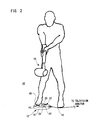
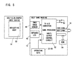
- the club-shaped input device 14 is irradiated by a light emission from the infrared-LED 42, and reflects the infrared light by the reflective body 50.
- the reflected light from the reflective body 50 is imaged by the image sensor 40, and the image sensor 40 outputs an image signal of the reflective body 50.
- the analog image signal from the image sensor 40 is converted into digital data by an A/D converter (not shown) included in a game processor 52.
- the game processor 52 intermittently blinks the infrared-LED 42 for the above-described strobe imaging.
- the processor 52 processes a digital image signal input from the image sensor 40 via the A/D converter to detect a movement of the golf-club-shaped input device 14, and executes an arithmetic operation, a graphic processing, a sound processing, etc. to output a video signal and an audio signal.
- the video signal is an image signal for displaying a game screen
- the audio signal is a signal for a game music and a sound effect. Accordingly, a game screen is displayed on the screen of a television monitor (not shown), and a necessary sound (sound effect, game music) is output from its speaker.
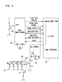
- a reset signal for resetting the image sensor 40 is output so as to be applied to the image sensor 40.
- a pixel data strobe signal and a frame status flag signal are output, and these signals are applied to the input port of the game processor 52.
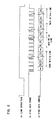
- the pixel data strobe signal is a strobe signal as shown in Figure 7 (b) for reading each of the pixel signals described above.
- the frame status flag signal is a flag signal for showing a state of the image sensor 40, and defines an exposure period of the image sensor 40 as shown in Figure 7 (a). A low level of the frame status signal shown in Figure 7 (a) indicates an exposure period, and a high level thereof shown in Figure 7 (a) indicates a non-exposure period.
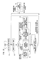
- a game is started by turning the power switch 20 shown in Figure 2 on. It is noted that the game processor 52 shown in Figure 5 executes an initialization process in a step S1. More specifically, the system and the respective variables are initialized.
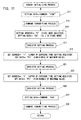
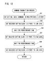
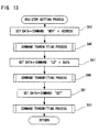
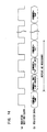
- the initialization process in the step S1 includes a data setting processing with respect to the control register contained in the image sensor 40, and is specifically executed according to the flowchart shown in Figure 11 to Figure 13 and at timing shown in Figure 14.
- a command transmitting process is executed shown in detail in Figure 12.
- the initialization process is executed in the step S1 shown in Figure 10. It is noted that the embodiment shown in Figure 11 to Figure 14 can be changed according to a specification of the image sensor to be used.
- the game processor 52 updates an image signal so as to update an image to be displayed on a monitor (not shown) in a step S2. It is noted that the update of the display image is executed for each frame (television frame or video frame).
- the game processor 52 executes a process according to a state. It is noted that it is a selection of the game mode that has to be processed first.
- a user or a game player selects a game mode such as one-player mode or a two-player mode by operating the selection key 22 shown in Figure 1, and sets a difficulty level of the game, and so on.
- an interruption occurs in response to a video synchronizing signal
- an image updating in the step S2 ( Figure 10) is executed.
- the sound processing in a step S7 is executed at a time of occurrence of a sound interruption, and whereby, a game music and a sound effect such as hitting a ball, and so on are output.
- the pixel data stored in the temporary register is stored as the elements [Y] [X] of the pixel data array.
- step S309 the X is incremented. If the X is less than 32, the process from the step S303 to the step S307 described above is repeatedly executed. If the X is equal to 32, that is, the fetch of the pixel data is reached to the end of the line, "-1" is set to the X in a following step S311 and the Y" is incremented in a step S313 to repeat the pixel data fetching process from the head pixel of the next line.
- the above-described pixel data array is stored as fetched data at N-th time lighting in the working area of the internal RAM, for example.
- step S79 the number of times register N is incremented in a step S79, and it is determined whether or not the number of times N reaches a predetermined value in a step S81. If “YES” in the step S81, the process returns to a step S57 (notable point extracting process). It is noted that if "NO", the process is returned to a preceding step S69.
- an infrared light is irradiated onto the reflective body 50 of the golf-club-shaped input device 14, and an image by the reflected infrared light incident to the image sensor 40 via the infrared filter is imaged.
- images of all things in the room as well as the light source such as the fluorescent light source, an incandescent light source, sunlight (window) are imaged on the image sensor (corresponding to the image sensor 40 in this embodiment) as shown in Figure 19 (A).
- Figure 19 (B) is an image signal when the image signal in Figure 19 (A) is subjected to a level discrimination at a certain threshold value.
- Such the level discriminating process can be executed by a dedicated hardware circuit or in respect of software.
- the level discrimination is executed for cutting pixel data having light amounts less than a predetermined amount, low luminance images except for the reflective body and the light source can be eliminated.
- a processing of the images except for the reflective body and the light source in the room are omitted, so that, it is possible to reduce the load of the computer while the high luminance images including the light source image is still imaged, and therefore, it is difficult to discriminate between the reflective body and the light source.
- the differences between the pixel data of the image data at a time of lighting up shown in Figure 19 (C) and the pixel data of the image data at a time of lighting out shown in Figure 19 (D) are calculated.
- the image by the differences is obtained as shown in Figure 19 (E).
- the image by the difference data includes only the images obtained from the reflective body of the golf-club-shaped input device 14. Accordingly, even the game processor 52 low in performance can obtain a moving path of the reflective body 50, that is, the club head 48 ( Figure 4) by the swing of the golf-club-shaped input device 14.
- the difference data array shown in Figure 19 (E), for example, is calculated in a step S105 shown in Figure 18.
- coordinates of a pixel having the largest value is obtained in a step S 107, and it is determined whether or not the luminance of the pixel at the coordinates exceeds the predetermined value in a step S109.
- step S109 it is determined whether or not pixels adjacent to the pixel at the coordinates obtained in the step S107, and pixels further adjacent thereto exceed the above-described predetermined value one after another to calculate a diameter ⁇ [N] of a notable portion (image of the reflective body in the embodiment) in a step S111.
- the reason why calculating the diameter (or size) of the notable portion is it is necessary that the height (Z coordinate) of the reflective body 50 is obtained in a step S113 and central coordinates of the reflective body are specified in a step S115.
- an optical system with a single focus is utilized for the imaging unit 28 of this embodiment. Therefore, when the distance between the reflective body 50 and the imaging device, that is, the image sensor 40 is coincident with the focus of the above-described optical system, the image is reduced in blur and increased in diameter. On the contrary thereto, the further the estrangement between the focused distance and the reflective body-image sensor distance is, the smaller the image itself becomes. In an example of Figure 19 (E) and Figure 21 described later, the size (diameter) of the image is changed depending upon the distance between the reflective body and the image sensor.
- the distance between the reflective body and the image sensor that is, the height of the reflective body 50 (Z coordinate) can be evaluated on the basis of the diameter (size) of the image of the reflective body.
- the Z coordinate is not utilized, by utilizing the Z coordinate as necessary, a further different game input can be provided.
- step S113 the Z coordinate is obtained, and in the step S115, central coordinates (X, Y or X, Y, Z) are saved.
- the N value of the number of times register is incremented in a step S117, and it is determined whether or not the number of times N exceeds a predetermined value in a step S119. If “YES” is determined in the step S119, the process is directly returned to the step S59 in Figure 15. However, if "NO” is determined, the process is returned to the preceding step S105 to execute the process in the step S105 onward.
- step S 109 determines whether or not all the predetermined number of data has been searched in a following step S121. If “YES” is determined in the step S121, that is, if all the predetermined number of pixels is searched, determining that the notable point is absent, the result of the search is stored in a step S 123. It is noted that if "NO" is determined in the step S121, the coordinates data of the pixel having the next largest luminance is obtained in a step S125, and then, the process returns to the step S107.
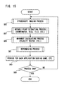
- the notable point extracting process is thus performed in the step S57, and then, a movement calculating process such as calculating the velocity vector, and so forth is executed in a following step S59.
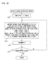
- FIG 20 shows a detailed embodiment of a velocity vector calculating process as one example of the movement calculating process.
- a step S127 in Figure 20 "1" is substituted for the number of times register N as described above.
- an N-th velocity vector (VX [N], VY [N]) is calculated by subtracting the (N-1)-th notable point coordinates (PX [N-1] PY [N-1]) from the N-th notable point coordinates (PX [N], PY [N]: Figure 21) so as to be stored in the internal memory.
- Figure 21 shows an image of the notable area at the first time having a diameter ⁇ [1], the central coordinates of the notable area at the first time are (PX [1], PY [1]), and the central coordinates of the notable area at the second time having a diameter ⁇ [2] is (PX [2], PY [2]).
- the notable areas third and the fourth time have diameters ⁇ [3] and ⁇ [4], respectively, and the central coordinates thereof are indicated by (PX [3], PY [3]) and (PX [4], PY [4]), respectively.
- the (N-1)-th notable area is the notable area at the first time.
- the velocity vector in an X direction VX [2] is rendered (PX [2] - PX [1])
- the velocity vector in a Y direction VY [2] is rendered (PY [2] - PY [1]).
- the number of times N is incremented in a step S131, and it is determined whether or not the N reaches the predetermined value in a following step S133. If "NO" in the step S133, the process returns to the preceding step S129 to repeat the process in the step S129.
- a determining process described in detail in Figure 22 is executed in a following step S61.
- the determining process it is determined whether or not the golf-club-shaped input device 14 is swung.
- "1" is substituted for N, and then, in a step S137, a velocity V [N] (scalar value) is calculated from the velocity vector at the N-th point (VX [N], VY [N]). Then, it is determined whether or not the velocity V [N] thus calculated exceeds the first threshold value in a following step S139.
- step S139 If "YES" in the step S139, it is directly determined the swing is performed in a step S141, and an initial velocity vector of the golf ball on hitting is evaluated from the velocity vector at the N-th point. Accordingly, in a case of the golf game system in this embodiment, a flying distance can be calculated from the initial velocity vector, the wind direction, the strength of the wind, and the geographical data.
- step S139 determines whether or not a line segment between the N-th point and the (N-1)-th point intersects a predetermined area in a step S145. Then, as a result of the determination, if "YES” is determined in a step S147, it is determined whether or not the speed at the N-th point (scalar value) exceeds a second threshold value in a step 149. It is noted that the second threshold value is naturally a value smaller than the first threshold value.
- step S149 the process proceeds to a preceding step S141 while if "NO”, the process proceeds to the step S151 just as “NO” in the step S147 to increment the value N. Then, it is determined whether N is larger than a predetermined value or not, and if "NO", the process returns to the preceding step S137 to repeatedly execute the steps onward. It is noted that if "NO" is determined in the step S153, that is, in a case that the line segment in the step S145 does not intersect the predetermined region, or even if the line segment intersects that area, in a case the velocity is smaller than the predetermined value, it is determined that the swing is not performed in the end.
- step S63 a process corresponding to the application such as the game and etc. is performed, and in a step S65, it is determined whether or not the process is ended (game over in a case of the game), and if "YES", the process is ended.
- the circle-shaped reflective body 50 is provided on the golf-club-shaped input device 14, the initial velocity vector is evaluated from the moving path, and regarding that the golf ball is hit at the initial velocity, the flying distance of the ball is calculated. That is, the rotation applied to the ball is ignored. This is because that it is impossible, if using the circle-shaped reflective body, to specify the orientation of the golf-club-shaped input device 14.
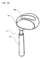
- the golf-club-shaped input device 14 shown in Figure 23 is utilized.
- an oval-shaped or rectangular-shaped reflective body 50A is utilized while the circle-shaped reflectivity body is utilized for the golf-club-shaped input device shown in the preceding Figure 4.
- a following step S165 it is determined whether or not pixels adjacent to the pixel of the coordinates obtained in the step S161 and a pixel adjacent to the pixel exceed the predetermined value one after another to extract all the pixels at the notable point (image of the reflective body in this embodiment). Then, in a step S166, two pixels of Pa (Xa, Ya) and Pb (Xb, Yb) that are the farthest from each other are extracted out of all the pixels of the notable point.
- the two points, as shown in Figure 26, indicate both ends of the rectangular-shaped reflective body 50A in the direction of the length. There are no points that are the farthest from each other except for the both ends of the long side.
- a tilt between the Pa and the Pb is calculated so as to be stored as angle data ⁇ [N] as shown in Figure 26. It is noted that the tilt ⁇ [N] is, as shown in the step S169, calculated as an arc tangent of (Xa-Xb)/(Ya-Yb).
- the direction of the golf-club-shaped input device 14 with respect to the imaging device is obtained as the angle data ⁇ [N].
- steps S181-S189 and steps S191-steps S201 are the same as the steps S135-S143 and the steps S145-S155 shown in Figure 22, respectively.
- the angle ⁇ j ( Figure 26) is calculated by the coordinates at N-th point and the coordinates at (N-1)-th point.
- the angle ⁇ j can be calculated by the arc tangent (PY [N] - PY [N-1])/ (PX [N] - PX [N-1]) as shown in the step S203.
- a bowling game system 78 of another embodiment according to this invention includes a game machine 80, and the game machine 80 is driven by an AC adaptor or a battery, and connected to an AV terminal (not shown) of a television monitor (not shown) through an AV cable 16 similarly to the game machine 12 in the game system in Figure 2.
- the game machine 78 further includes a housing 82, and on the housing 82, a power switch 84 is provided, and a direction button 86, a determination key 88, and a cancel key 90 are also provided. These buttons or operation keys have the same function as corresponding ones in Figure 2.
- a part of the housing 82 of the game machine 80 is partly cut away, and at that place, a movable body 92 is rotatably supported in an elevation direction.
- the imaging unit 28 described with referring to Figure 3 is housed, and therefore, the movable body 92 is provided with an image sensor 40 similarly to the above-described one.
- an infrared-LED 42 is provided on the side surface of the movable body 92 in proximity to the image sensor 40 and in an integrated manner with the image sensor 40 so as to be moved in the elevation direction, and constitutes a stroboscope imaging means.
- the movable body 92 is supported such that it has constant degree of freedom in the elevation direction in this embodiment.
- the degree of freedom may be provided in a revolution direction in place of the elevation direction, or in addition to the elevation direction.
- the movable body 92 that is, the image sensor 40 and the infrared-LED 42 are provided changeable in an arbitrary direction.
- the image sensor 40 needs not to be movable, and alternatively fixedly attached to the image sensor 40.
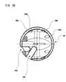
- a ball-shaped input device 94 has holes 94a, 94b, and 94c into which three fingers of the user, that is, a thumb, a middle finger, and a ring finger are respectively inserted as does in the real bowling game, and is provided with a wider hole 94d into which a child can insert any one or a plurality fingers except for the thumb. Then, a strap 96 is provided, and therefore, the game player equips it in his arms (upper arm or front arm) in order to assure the safety of the player.
- the ball-shaped input device 94 is coupled to his arm by the strap 96, and therefore, even if the game player releases the ball-shaped input device 94 from his fingers as does in the real bowling game, it is possible to prevent accidents of the ball-shaped input device 94 being flown away, being hit against the player himself or others, and so forth.
- the ball-shaped input device 94 in this embodiment forms the housing of the ball-shaped input device 94 by connecting transparent or translucent hemisphere outer shells 98A and 98B to each other by bosses, and inside the hemisphere outer shells 98A and 98B, hemisphere inner shells 100A and 100B that are similarly coupled to each other by bosses are fixed. Then, a reflective sheet is pasted on the surface of the respective hemisphere inner shells 100A and 100B to form a reflective body. That is, the inner shells become the reflective body. Accordingly, the reference numeral 100 is assigned to the reflective body in this embodiment.
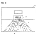
- the movement of the ball-shaped input device 94 is detected by the stroboscope, and whereby, a position of a bowling ball 104 is controlled on a game screen 102 as shown in Figure 29.
- the game screen 102 is displayed as a perspective image viewed from a viewpoint of the user or the player. That is, on the game screen 102, a bowling lane 106 and pins 108 arranged in a depth direction are displayed.
- the bowling ball 104 is moved on the lane 106, and in correspondence to a reached position and intensity, the pins are knocked down as do in the real bowling game. It is noted that if from directly before the bowling ball 104 hit the pins 108, an enlarged image of the pins portion is displayed on the window (not shown) at the center of the screen, for example, so much presence can be provided to the players.
- the game processor 52 ( Figure 31) intermittently turns the infrared-LED 42 on, and intermittently detects the positions of the ball-shaped input device 94 by analyzing and processing the images of the CMOS image sensor 40 at each lighting-up time and lighting-out time. Then, in correspondence to the positions (coordinates) of the ball-shaped input device 94, the movement of the bowling ball 104 is controlled to knock down zero or more pins.
- the ball-shaped input device 94 as described above is irradiated by a light emission from the infrared-LED 42, and reflects the infrared ray by the reflective body 100.
- the reflected light from the reflective body 100 is imaged by the CMOS image sensor 40, and whereby, an image signal of the reflective body 100 is output from the CMOS image sensor 40.
- the other part is the same as the golf game system 10 shown in Figure 5.
- the game processor 52 updates an image signal to update an image to be displayed on the monitor 20 in a step S2. It is noted that the update of the display image is executed every one frame (television frame or video frame).
- a process to be executed first is a game mode selection.
- the user or the game player selects the game mode such as an one-player mode, a two-player mode, etc. by operating the selection key 86 shown in Figure 27, and sets a difficulty level of the game in a step S3 in Figure 32.
- a throwing action is performed by use of the ball-shaped input device 94 as described above.
- the game processor 52 executes a throwing determining process to determine whether or not the throwing action is performed in a step S4. Then, if the throwing action is performed, when the ball 104 moves on the lane 106 (the both in Figure 30), the ball path is calculated and a hitting determining process of the ball 104 against the pins 108 ( Figure 30) is executed in a step S5. Then, when the ball 104 reaches the end of the lane 106, a score calculating and result determining process is executed in a step S6 as the result of the pin hitting determining process in the step S5.
- the throwing determining process step is shown in detail in Figure 33, and an N value is set to "1" in a first step S207. Then, in a step S209, it is determined whether or not a Y component of the velocity vector (component in up and down directions) VY [N] ( Figure 21) exceeds a predetermined value. If “YES” in the step S209, the process proceeds to a step S211 to increment a counter formed in an internal memory, for example. Then, in a next step S213, it is determined whether or not a count value of the counter is a predetermined constant C (for example, "3"). If "YES", it is determined that a throwing action is performed in a step S215.
- step S217 the X coordinate PX [N] at the N-th point is rendered as the X coordinate at the throwing position, and in a step S 219, an initial velocity of the ball on throwing is evaluated from the velocity vector at N-th point (VX [N], VY [N]). Then, according to the initial velocity, regarding that the bowling ball is thrown, the game processing is executed.
- step S209 the above-described counter is reset in a step S221. Accordingly, the throwing action is not determined until the Y component of the velocity vector exceeds the predetermined value successive three times, for example. Thus, it is possible to prevent an undesired action of the game player from being reflected on the game.
- the N value is incremented in a step S223, and it is determined whether or not the N value reaches a predetermined value in a step S225. If "YES" is determined, it is determined that the throwing is not performed in a step S227. Then, the process returns to the step S63 in Figure 15 similarly to the step S219 onward.
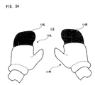
- FIG 34 shows another embodiment of an input device utilizing a stroboscope.
- the input device 112 of this embodiment is a glove-shaped input device.
- the glove-shaped input device 112 includes gloves 114L and 114R to be attached to both right and left hands, and reflective bodies 116L and 116R in the form of the reflective sheet are provided at predetermined positions (the tip end portion) of the gloves 1141 and 114R.
- These reflective bodies 116L and 116R are respectively formed as a part of the gloves 114L and 114R, and alternatively may be pasted on the gloves 114L and 114R.
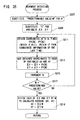
- a moving average is detected or calculated to obtain an input.
- a "predetermined value -M" is set to the number-of-times register N.
- "0" is set into the variables ⁇ X and ⁇ Y.
- a step S211 coordinates (PX [N], PY [N]): Figure 21) at N-th time are obtained. It is noted that in a case of N ⁇ 1, coordinates data is obtained from coordinate information of the last time.
- the coordinates obtained in the step S211 are respectively added to the variables ⁇ X and ⁇ Y initialized in the step S209 to update the variables ⁇ X and ⁇ Y. This process is repeated until it is detected in a step S217 that the number of times N incremented in the step S215 reaches the predetermined value. Accordingly, the game processor 52 stores, at this time, the variables ⁇ X and ⁇ Y to which M sets of coordinates are added.
- each of the variables ⁇ X and ⁇ Y is divided by the number M to calculate the moving average (AX, AY).
- the game processor 52 changes positions of moving objects that can be operated by the player on the game screen.
- the input is performed by the use of the golf-club-shaped input device 14.
- a number of modifications are conceivable including a baseball game apparatus by use of a bat-shaped input device for baseball and/or a ball-shaped input device for baseball, a table tennis game by use of a racket-shaped input device for table tennis, a tennis game by use of a racket-shaped input device for tennis, etc.
- a modification of soccer game apparatus in which by attaching an input device provided with a reflective body around the part of the lower leg or the ankle, a position, velocity, a pattern of a moving path of the leg of the player are used as an input signal.
- a moving average value calculated in the flowchart in Figure 35 is utilized as an input signal.
- modifications including a boxing game apparatus and a dancing game apparatus are conceivable, in which a position, a moving velocity, a moving path of the glove-shaped input device are calculated to be used as an input signal.
- a wristband shaped input device wrapped around the wrist secures the same effect as the glove-shaped input device.
- a further modification including a dancing game apparatus utilizing the arms and the legs is conceivable, in which the above described input device wrapped around the leg is used in combination with the glove-shaped input device shown in Figure 34 or the wristband shaped input device.
- an object is imaged by use of the stroboscope and the imaging means, and on the basis of the difference between the plurality of image signals at a time of lighting up and an image signal at a time of lighting out, a part or all of the information of the position, the size, the velocity, the acceleration, and the moving path pattern are calculated.
- the information processing apparatus and an entertainment apparatus execute the information processing, the game, and other entertainment processing by use of the information.
Landscapes
- Engineering & Computer Science (AREA)
- Multimedia (AREA)
- Computer Vision & Pattern Recognition (AREA)
- Physics & Mathematics (AREA)
- General Physics & Mathematics (AREA)
- Theoretical Computer Science (AREA)
- Human Computer Interaction (AREA)
- Length Measuring Devices By Optical Means (AREA)
- Image Processing (AREA)
- Studio Devices (AREA)
- Image Analysis (AREA)
Applications Claiming Priority (5)
| Application Number | Priority Date | Filing Date | Title |
|---|---|---|---|
| JP2002187162 | 2002-06-27 | ||
| JP2002187162 | 2002-06-27 | ||
| JP2002346052A JP5109221B2 (ja) | 2002-06-27 | 2002-11-28 | ストロボスコープを使った入力システムを備える情報処理装置 |
| JP2002346052 | 2002-11-28 | ||
| PCT/JP2003/007900 WO2004002593A1 (ja) | 2002-06-27 | 2003-06-20 | ストロボスコープを使った入力システムを備える情報処理装置 |
Publications (2)
| Publication Number | Publication Date |
|---|---|
| EP1516654A1 true EP1516654A1 (de) | 2005-03-23 |
| EP1516654A4 EP1516654A4 (de) | 2011-05-04 |
Family
ID=30002297
Family Applications (1)
| Application Number | Title | Priority Date | Filing Date |
|---|---|---|---|
| EP03733531A Withdrawn EP1516654A4 (de) | 2002-06-27 | 2003-06-20 | Informationsprozessor mit eingabesystem unter verwendung eines stroboskops |
Country Status (8)
| Country | Link |
|---|---|
| US (2) | US7662047B2 (de) |
| EP (1) | EP1516654A4 (de) |
| JP (1) | JP5109221B2 (de) |
| KR (1) | KR101009161B1 (de) |
| CN (1) | CN100528273C (de) |
| AU (1) | AU2003243940A1 (de) |
| TW (1) | TWI325789B (de) |
| WO (1) | WO2004002593A1 (de) |
Cited By (2)
| Publication number | Priority date | Publication date | Assignee | Title |
|---|---|---|---|---|
| EP1715407A3 (de) * | 2005-04-21 | 2008-05-07 | Avago Technologies ECBU IP (Singapore) Pte. Ltd. | Positionsbestimmung mittels schnurloser Vorrichtung |
| US7719741B2 (en) | 2004-08-24 | 2010-05-18 | Ssd Company Limited | Input device |
Families Citing this family (86)
| Publication number | Priority date | Publication date | Assignee | Title |
|---|---|---|---|---|
| US7749089B1 (en) | 1999-02-26 | 2010-07-06 | Creative Kingdoms, Llc | Multi-media interactive play system |
| US7789742B1 (en) * | 1999-05-12 | 2010-09-07 | Wilbert Q. Murdock | Smart golf club multiplayer system for the internet |
| US7878905B2 (en) | 2000-02-22 | 2011-02-01 | Creative Kingdoms, Llc | Multi-layered interactive play experience |
| US6761637B2 (en) | 2000-02-22 | 2004-07-13 | Creative Kingdoms, Llc | Method of game play using RFID tracking device |
| US7445550B2 (en) | 2000-02-22 | 2008-11-04 | Creative Kingdoms, Llc | Magical wand and interactive play experience |
| US7066781B2 (en) | 2000-10-20 | 2006-06-27 | Denise Chapman Weston | Children's toy with wireless tag/transponder |
| US6967566B2 (en) | 2002-04-05 | 2005-11-22 | Creative Kingdoms, Llc | Live-action interactive adventure game |
| US20070066396A1 (en) | 2002-04-05 | 2007-03-22 | Denise Chapman Weston | Retail methods for providing an interactive product to a consumer |
| JP5109221B2 (ja) * | 2002-06-27 | 2012-12-26 | 新世代株式会社 | ストロボスコープを使った入力システムを備える情報処理装置 |
| US7883415B2 (en) | 2003-09-15 | 2011-02-08 | Sony Computer Entertainment Inc. | Method and apparatus for adjusting a view of a scene being displayed according to tracked head motion |
| US8797260B2 (en) | 2002-07-27 | 2014-08-05 | Sony Computer Entertainment Inc. | Inertially trackable hand-held controller |
| US9474968B2 (en) | 2002-07-27 | 2016-10-25 | Sony Interactive Entertainment America Llc | Method and system for applying gearing effects to visual tracking |
| US8313380B2 (en) | 2002-07-27 | 2012-11-20 | Sony Computer Entertainment America Llc | Scheme for translating movements of a hand-held controller into inputs for a system |
| US8570378B2 (en) | 2002-07-27 | 2013-10-29 | Sony Computer Entertainment Inc. | Method and apparatus for tracking three-dimensional movements of an object using a depth sensing camera |
| US7760248B2 (en) | 2002-07-27 | 2010-07-20 | Sony Computer Entertainment Inc. | Selective sound source listening in conjunction with computer interactive processing |
| US8686939B2 (en) | 2002-07-27 | 2014-04-01 | Sony Computer Entertainment Inc. | System, method, and apparatus for three-dimensional input control |
| US9393487B2 (en) | 2002-07-27 | 2016-07-19 | Sony Interactive Entertainment Inc. | Method for mapping movements of a hand-held controller to game commands |
| US9682319B2 (en) | 2002-07-31 | 2017-06-20 | Sony Interactive Entertainment Inc. | Combiner method for altering game gearing |
| US7674184B2 (en) | 2002-08-01 | 2010-03-09 | Creative Kingdoms, Llc | Interactive water attraction and quest game |
| US8745541B2 (en) * | 2003-03-25 | 2014-06-03 | Microsoft Corporation | Architecture for controlling a computer using hand gestures |
| US7665041B2 (en) * | 2003-03-25 | 2010-02-16 | Microsoft Corporation | Architecture for controlling a computer using hand gestures |
| US9446319B2 (en) | 2003-03-25 | 2016-09-20 | Mq Gaming, Llc | Interactive gaming toy |
| US8072470B2 (en) | 2003-05-29 | 2011-12-06 | Sony Computer Entertainment Inc. | System and method for providing a real-time three-dimensional interactive environment |
| US8512160B2 (en) * | 2003-09-08 | 2013-08-20 | Acushnet Company | Multishutter club-ball analyzer |
| US10279254B2 (en) | 2005-10-26 | 2019-05-07 | Sony Interactive Entertainment Inc. | Controller having visually trackable object for interfacing with a gaming system |
| US8323106B2 (en) | 2008-05-30 | 2012-12-04 | Sony Computer Entertainment America Llc | Determination of controller three-dimensional location using image analysis and ultrasonic communication |
| US7874917B2 (en) | 2003-09-15 | 2011-01-25 | Sony Computer Entertainment Inc. | Methods and systems for enabling depth and direction detection when interfacing with a computer program |
| US9573056B2 (en) | 2005-10-26 | 2017-02-21 | Sony Interactive Entertainment Inc. | Expandable control device via hardware attachment |
| US8287373B2 (en) | 2008-12-05 | 2012-10-16 | Sony Computer Entertainment Inc. | Control device for communicating visual information |
| JP2005349048A (ja) * | 2004-06-11 | 2005-12-22 | Konami Co Ltd | ゲーム装置、ゴルフゲーム装置及び該装置のショット結果決定方法 |
| US8547401B2 (en) | 2004-08-19 | 2013-10-01 | Sony Computer Entertainment Inc. | Portable augmented reality device and method |
| JP2008512643A (ja) * | 2004-09-09 | 2008-04-24 | 新世代株式会社 | 傾き検出方法及びエンタテインメント・システム |
| CN101068605B (zh) * | 2004-12-03 | 2011-07-13 | 新世代株式会社 | 拳击游戏的处理方法,显示控制方法,位置检测方法,光标控制方法,能量消耗计算方法和练习系统 |
| US20060141433A1 (en) * | 2004-12-28 | 2006-06-29 | Hing Cheung C | Method of detecting position of rectangular object and object detector |
| WO2006070850A1 (en) * | 2004-12-28 | 2006-07-06 | Ssd Company Limited | Method and apparatus for detecting reflective object |
| WO2006073936A2 (en) * | 2005-01-04 | 2006-07-13 | Qmotions, Inc. | Baseball simulation device |
| TW200625143A (en) * | 2005-01-04 | 2006-07-16 | Pixart Imaging Inc | Personal computer's interactive input device and game-peripheral equipment |
| JP4635164B2 (ja) * | 2005-01-27 | 2011-02-16 | 新世代株式会社 | 傾き検出方法、コンピュータプログラム、及びエンタテインメント・システム |
| WO2006080546A1 (en) * | 2005-01-27 | 2006-08-03 | Ssd Company Limited | Tilt detection method and entertainment system |
| JP2007152080A (ja) * | 2005-06-16 | 2007-06-21 | Shinsedai Kk | 入力装置、疑似体験方法及びエンタテインメント・システム |
| CN100583008C (zh) * | 2005-06-16 | 2010-01-20 | 新世代株式会社 | 输入装置及模拟体验方法 |
| CN101898041A (zh) * | 2005-06-16 | 2010-12-01 | 新世代株式会社 | 信息处理系统及用于控制信息处理系统的方法 |
| JP4805633B2 (ja) | 2005-08-22 | 2011-11-02 | 任天堂株式会社 | ゲーム用操作装置 |
| US7927216B2 (en) | 2005-09-15 | 2011-04-19 | Nintendo Co., Ltd. | Video game system with wireless modular handheld controller |
| US8313379B2 (en) | 2005-08-22 | 2012-11-20 | Nintendo Co., Ltd. | Video game system with wireless modular handheld controller |
| JP4262726B2 (ja) | 2005-08-24 | 2009-05-13 | 任天堂株式会社 | ゲームコントローラおよびゲームシステム |
| US8308563B2 (en) | 2005-08-30 | 2012-11-13 | Nintendo Co., Ltd. | Game system and storage medium having game program stored thereon |
| US8157651B2 (en) | 2005-09-12 | 2012-04-17 | Nintendo Co., Ltd. | Information processing program |
| WO2007069752A1 (ja) * | 2005-12-12 | 2007-06-21 | Ssd Company Limited | 運動支援方法、運動器具、及び情報処理装置 |
| US8636605B2 (en) * | 2006-03-01 | 2014-01-28 | Acushnet Company | IR system for kinematic analysis |
| KR101060779B1 (ko) * | 2006-05-04 | 2011-08-30 | 소니 컴퓨터 엔터테인먼트 아메리카 엘엘씨 | 시각, 음향, 관성, 및 혼합 데이터 중 하나 이상에 근거하여 기어링 효과들을 입력에 적용하기 위한 방법들 및장치들 |
| JP4989105B2 (ja) * | 2006-05-09 | 2012-08-01 | 任天堂株式会社 | ゲームコントローラ |
| US8781151B2 (en) | 2006-09-28 | 2014-07-15 | Sony Computer Entertainment Inc. | Object detection using video input combined with tilt angle information |
| US8310656B2 (en) | 2006-09-28 | 2012-11-13 | Sony Computer Entertainment America Llc | Mapping movements of a hand-held controller to the two-dimensional image plane of a display screen |
| USRE48417E1 (en) | 2006-09-28 | 2021-02-02 | Sony Interactive Entertainment Inc. | Object direction using video input combined with tilt angle information |
| US7907183B2 (en) | 2006-10-30 | 2011-03-15 | Panasonic Corporation | Image generation apparatus and image generation method for generating a new video sequence from a plurality of video sequences |
| US9283464B2 (en) * | 2007-08-03 | 2016-03-15 | Lynqs, Inc. | Golf gaming systems and methods |
| US8926416B2 (en) * | 2007-08-10 | 2015-01-06 | Full Swing Golf | Sports simulator and simulation method |
| US20090062002A1 (en) * | 2007-08-30 | 2009-03-05 | Bay Tek Games, Inc. | Apparatus And Method of Detecting And Tracking Objects In Amusement Games |
| US8542907B2 (en) | 2007-12-17 | 2013-09-24 | Sony Computer Entertainment America Llc | Dynamic three-dimensional object mapping for user-defined control device |
| JP5429918B2 (ja) * | 2008-02-15 | 2014-02-26 | 任天堂株式会社 | 情報処理プログラムおよび情報処理装置 |
| EP2257911B1 (de) | 2008-02-27 | 2018-10-10 | Sony Computer Entertainment America LLC | Verfahren zur erfassung von tiefendaten einer szene und anwendung von computeraktionen |
| US8368753B2 (en) | 2008-03-17 | 2013-02-05 | Sony Computer Entertainment America Llc | Controller with an integrated depth camera |
| JP2009250772A (ja) * | 2008-04-04 | 2009-10-29 | Sony Corp | 位置検出システム、位置検出方法、プログラム、物体判断システム、および物体判断方法 |
| US8672759B2 (en) * | 2008-05-06 | 2014-03-18 | Sony Computer Entertainment America Llc | Gaming peripheral including releasably engageable release element |
| US8961313B2 (en) | 2009-05-29 | 2015-02-24 | Sony Computer Entertainment America Llc | Multi-positional three-dimensional controller |
| WO2010083449A2 (en) | 2009-01-19 | 2010-07-22 | Full Swing Golf, Inc. | Methods and systems for sports simulation |
| US8527657B2 (en) | 2009-03-20 | 2013-09-03 | Sony Computer Entertainment America Llc | Methods and systems for dynamically adjusting update rates in multi-player network gaming |
| US8342963B2 (en) | 2009-04-10 | 2013-01-01 | Sony Computer Entertainment America Inc. | Methods and systems for enabling control of artificial intelligence game characters |
| US8142288B2 (en) | 2009-05-08 | 2012-03-27 | Sony Computer Entertainment America Llc | Base station movement detection and compensation |
| US8393964B2 (en) | 2009-05-08 | 2013-03-12 | Sony Computer Entertainment America Llc | Base station for position location |
| US8854471B2 (en) * | 2009-11-13 | 2014-10-07 | Korea Institute Of Science And Technology | Infrared sensor and sensing method using the same |
| JP2011186636A (ja) * | 2010-03-05 | 2011-09-22 | Sony Corp | 情報処理装置および方法、並びにプログラム |
| US9384329B2 (en) * | 2010-06-11 | 2016-07-05 | Microsoft Technology Licensing, Llc | Caloric burn determination from body movement |
| JP5849622B2 (ja) * | 2011-11-08 | 2016-01-27 | 株式会社リコー | 撮像装置及び撮像方法 |
| US8811938B2 (en) | 2011-12-16 | 2014-08-19 | Microsoft Corporation | Providing a user interface experience based on inferred vehicle state |
| US9587804B2 (en) | 2012-05-07 | 2017-03-07 | Chia Ming Chen | Light control systems and methods |
| US9416959B2 (en) | 2012-05-17 | 2016-08-16 | Donald Spinner | Illuminated golf |
| DE102013225283B4 (de) * | 2013-12-09 | 2023-04-27 | Rohde & Schwarz GmbH & Co. Kommanditgesellschaft | Verfahren und Vorrichtung zum Erfassen einer Rundumansicht |
| EP3146262A4 (de) | 2014-04-29 | 2018-03-14 | Chia Ming Chen | Lichtsteuerungssysteme und -verfahren |
| JP6566449B2 (ja) * | 2015-03-18 | 2019-08-28 | 国立研究開発法人理化学研究所 | 球状体の回転の測定装置、測定方法、ならびに、プログラム |
| WO2017051592A1 (ja) * | 2015-09-25 | 2017-03-30 | ソニー株式会社 | 情報処理装置、情報処理方法、およびプログラム |
| EP3502841B1 (de) * | 2016-08-18 | 2023-07-26 | Sony Group Corporation | Informationsverarbeitungsvorrichtung, informationsverarbeitungssystem und informationsverarbeitungsverfahren |
| US20180353828A1 (en) * | 2017-06-09 | 2018-12-13 | Golftech, Llc | Method and apparatus for ball flight analysis |
| EP4011468A1 (de) | 2017-06-22 | 2022-06-15 | Centurion VR, Inc. | Simulation einer virtuellen realität |
| CN118864532B (zh) * | 2024-07-05 | 2025-08-26 | 深圳市得乐体育科技有限公司 | 一种网球碰撞检测方法以及装置 |
Family Cites Families (50)
| Publication number | Priority date | Publication date | Assignee | Title |
|---|---|---|---|---|
| US2223849A (en) * | 1939-05-04 | 1940-12-03 | Little Inc A | Means for analyzing motion |
| US3577153A (en) * | 1967-08-23 | 1971-05-04 | Tokyo Shibaura Electric Co | Image pickup apparatus |
| JPS5596405A (en) * | 1979-01-19 | 1980-07-22 | Hajime Sangyo Kk | Inspection device for moving object |
| JPS5684088A (en) * | 1979-12-12 | 1981-07-09 | Stanley Electric Co Ltd | Picture signal transmitting method |
| US4713686A (en) * | 1985-07-02 | 1987-12-15 | Bridgestone Corporation | High speed instantaneous multi-image recorder |
| US5111410A (en) * | 1989-06-23 | 1992-05-05 | Kabushiki Kaisha Oh-Yoh Keisoku Kenkyusho | Motion analyzing/advising system |
| US5062641A (en) * | 1989-09-28 | 1991-11-05 | Nannette Poillon | Projectile trajectory determination system |
| JP2893052B2 (ja) * | 1990-07-31 | 1999-05-17 | 株式会社エフ・エフ・シー | 三次元特徴点座標抽出方法 |
| JPH0777590B2 (ja) * | 1991-01-16 | 1995-08-23 | 美津濃株式会社 | ゴルフゲーム模擬装置 |
| US5249967A (en) * | 1991-07-12 | 1993-10-05 | George P. O'Leary | Sports technique video training device |
| US5246232A (en) * | 1992-01-22 | 1993-09-21 | Colorado Time Systems | Method and apparatus for determining parameters of the motion of an object |
| US5471383A (en) * | 1992-01-22 | 1995-11-28 | Acushnet Company | Monitoring systems to measure and display flight characteristics of moving sports object |
| US5288080A (en) * | 1992-04-08 | 1994-02-22 | Tice David E | Stroboscopic practice golf club |
| JPH0686174A (ja) | 1992-08-31 | 1994-03-25 | Nec Corp | 赤外線イメージセンサ |
| US5982352A (en) * | 1992-09-18 | 1999-11-09 | Pryor; Timothy R. | Method for providing human input to a computer |
| CA2102442A1 (en) * | 1992-11-20 | 1994-05-21 | William Gobush | Method and apparatus to determine object striking instrument movement conditions |
| US7086954B2 (en) * | 2001-02-14 | 2006-08-08 | Acushnet Company | Performance measurement system with fluorescent markers for golf equipment |
| US5575719A (en) * | 1994-02-24 | 1996-11-19 | Acushnet Company | Method and apparatus to determine object striking instrument movement conditions |
| US5612781A (en) * | 1993-09-09 | 1997-03-18 | Kabushiki Kaisha Topcon | Object reflector detection system |
| JPH07151701A (ja) * | 1993-11-29 | 1995-06-16 | Hajime Sangyo Kk | ストロボスコープの光量補正機能を有する検査装置 |
| JPH07154777A (ja) | 1993-11-30 | 1995-06-16 | Matsushita Electric Ind Co Ltd | 画像処理装置およびテレビ電話装置 |
| US5478239A (en) * | 1993-12-21 | 1995-12-26 | Maximum Performance, Inc. | Dynamic visual acuity training method and apparatus |
| US5472205A (en) * | 1994-06-20 | 1995-12-05 | Thrustmaster, Inc. | Opto-electric golf club swing sensing system and method |
| WO1996011726A1 (en) * | 1994-10-17 | 1996-04-25 | Mizuno Corporation | Apparatus for selecting shaft having optimum flex for golfer |
| JP3463379B2 (ja) | 1994-10-19 | 2003-11-05 | カシオ計算機株式会社 | 画像制御装置及び画像制御方法 |
| JP3540485B2 (ja) * | 1995-04-13 | 2004-07-07 | 株式会社リコー | 電子スチルカメラ |
| JPH08287216A (ja) | 1995-04-18 | 1996-11-01 | Sanyo Electric Co Ltd | 顔面内部位認識方法 |
| US5833549A (en) * | 1995-11-14 | 1998-11-10 | Interactive Light, Inc. | Sports trainer and game |
| JP3712459B2 (ja) * | 1996-02-14 | 2005-11-02 | 藤倉ゴム工業株式会社 | ゴルフクラブヘッドのスイング挙動測定方法 |
| JP3410919B2 (ja) * | 1997-01-31 | 2003-05-26 | 株式会社東芝 | 画像抽出装置 |
| EP0837418A3 (de) * | 1996-10-18 | 2006-03-29 | Kabushiki Kaisha Toshiba | Verfahren und System zum Erzeugen von Eingabeinformationen unter Verwendung des Zielobjektbildes, das aus reflektiertem Licht hergestellt ist |
| JP3187748B2 (ja) * | 1996-10-30 | 2001-07-11 | ブリヂストンスポーツ株式会社 | ゴルフボールの運動測定方法 |
| US6292169B1 (en) * | 1998-02-13 | 2001-09-18 | Kabushiki Kaisha Toshiba | Information input apparatus |
| US6227984B1 (en) * | 1998-05-01 | 2001-05-08 | Charles H. Blankenship | Golf swing analysis methods |
| US6086487A (en) * | 1999-04-02 | 2000-07-11 | Acushnet Company | Method for matching golfer with a ball |
| JP2001209487A (ja) | 2000-01-25 | 2001-08-03 | Uw:Kk | 筆跡通信システムおよび該システムで使用される筆跡入力装置及び筆跡表示装置 |
| JP2001222375A (ja) | 2000-02-08 | 2001-08-17 | Seiko Epson Corp | 指示位置検出システムおよび方法、プレゼンテーションシステム並びに情報記憶媒体 |
| JP2001264016A (ja) * | 2000-03-15 | 2001-09-26 | Sumitomo Rubber Ind Ltd | ボールの運動測定装置 |
| JP3749072B2 (ja) * | 2000-03-24 | 2006-02-22 | ブリヂストンスポーツ株式会社 | ゴルフクラブ選択方法及び選択システム |
| AU2001253224A1 (en) * | 2000-04-07 | 2001-10-23 | Businger, Peter A. | Automated stroboscoping of video sequences |
| JP2002027315A (ja) | 2000-07-07 | 2002-01-25 | Sony Corp | 動き検出装置及び動き検出方法 |
| US6431990B1 (en) * | 2001-01-19 | 2002-08-13 | Callaway Golf Company | System and method for measuring a golfer's ball striking parameters |
| US6859565B2 (en) * | 2001-04-11 | 2005-02-22 | Hewlett-Packard Development Company, L.P. | Method and apparatus for the removal of flash artifacts |
| US6821211B2 (en) * | 2001-09-14 | 2004-11-23 | Golftech | Sport swing analysis system |
| US6506124B1 (en) * | 2001-12-21 | 2003-01-14 | Callaway Golf Company | Method for predicting a golfer's ball striking performance |
| JP5109221B2 (ja) * | 2002-06-27 | 2012-12-26 | 新世代株式会社 | ストロボスコープを使った入力システムを備える情報処理装置 |
| US20040063480A1 (en) * | 2002-09-30 | 2004-04-01 | Xiaoling Wang | Apparatus and a method for more realistic interactive video games on computers or similar devices |
| US7322889B2 (en) * | 2003-10-23 | 2008-01-29 | Ssd Company Limited | Game for moving an object on a screen in response to movement of an operation article |
| US7554545B2 (en) * | 2003-11-04 | 2009-06-30 | Ssd Company Limited | Drawing apparatus operable to display a motion path of an operation article |
| US20060141433A1 (en) * | 2004-12-28 | 2006-06-29 | Hing Cheung C | Method of detecting position of rectangular object and object detector |
-
2002
- 2002-11-28 JP JP2002346052A patent/JP5109221B2/ja not_active Expired - Fee Related
-
2003
- 2003-06-20 KR KR1020047021046A patent/KR101009161B1/ko not_active Expired - Fee Related
- 2003-06-20 AU AU2003243940A patent/AU2003243940A1/en not_active Abandoned
- 2003-06-20 CN CNB038150867A patent/CN100528273C/zh not_active Expired - Fee Related
- 2003-06-20 EP EP03733531A patent/EP1516654A4/de not_active Withdrawn
- 2003-06-20 WO PCT/JP2003/007900 patent/WO2004002593A1/ja not_active Ceased
- 2003-06-20 US US10/517,767 patent/US7662047B2/en not_active Expired - Fee Related
- 2003-06-24 TW TW092117063A patent/TWI325789B/zh not_active IP Right Cessation
-
2009
- 2009-12-02 US US12/629,615 patent/US8083604B2/en not_active Expired - Fee Related
Cited By (5)
| Publication number | Priority date | Publication date | Assignee | Title |
|---|---|---|---|---|
| US7719741B2 (en) | 2004-08-24 | 2010-05-18 | Ssd Company Limited | Input device |
| EP1715407A3 (de) * | 2005-04-21 | 2008-05-07 | Avago Technologies ECBU IP (Singapore) Pte. Ltd. | Positionsbestimmung mittels schnurloser Vorrichtung |
| US7609249B2 (en) | 2005-04-21 | 2009-10-27 | Avago Technologies Ecbu Ip (Singapore) Pte. Ltd. | Position determination utilizing a cordless device |
| US7812816B2 (en) | 2005-04-21 | 2010-10-12 | Avago Technologies Ecbu Ip (Singapore) Pte. Ltd. | Powerless signal generation for use in conjunction with a powerless position determination device |
| US8384663B2 (en) | 2005-04-21 | 2013-02-26 | Avago Technologies General Ip (Singapore) Pte. Ltd. | Position determination utilizing a cordless device |
Also Published As
| Publication number | Publication date |
|---|---|
| TW200405111A (en) | 2004-04-01 |
| AU2003243940A1 (en) | 2004-01-19 |
| CN100528273C (zh) | 2009-08-19 |
| KR20050014018A (ko) | 2005-02-05 |
| US8083604B2 (en) | 2011-12-27 |
| JP2004085524A (ja) | 2004-03-18 |
| US20100309370A1 (en) | 2010-12-09 |
| CN1665571A (zh) | 2005-09-07 |
| US20050239548A1 (en) | 2005-10-27 |
| TWI325789B (en) | 2010-06-11 |
| EP1516654A4 (de) | 2011-05-04 |
| JP5109221B2 (ja) | 2012-12-26 |
| US7662047B2 (en) | 2010-02-16 |
| WO2004002593A1 (ja) | 2004-01-08 |
| KR101009161B1 (ko) | 2011-01-19 |
Similar Documents
| Publication | Publication Date | Title |
|---|---|---|
| US7662047B2 (en) | Information processor having input system using stroboscope | |
| US8206219B2 (en) | Interactive gaming apparel for interactive gaming | |
| US7933431B2 (en) | Camera based sensing in handheld, mobile, gaming, or other devices | |
| JP5819580B2 (ja) | ゲームプログラム、ゲーム装置、ゲームシステムおよびゲーム制御方法 | |
| JP6834614B2 (ja) | 情報処理装置、情報処理方法、およびプログラム | |
| US20040063481A1 (en) | Apparatus and a method for more realistic interactive video games on computers or similar devices using visible or invisible light and an input computing device | |
| EP1970104A1 (de) | Trainingsverfahren, trainingsvorrichtung und koordinationstrainingsverfahren | |
| JP2011067239A (ja) | 情報処理プログラムおよび情報処理装置 | |
| CN110520822B (zh) | 控制装置、信息处理系统、控制方法和程序 | |
| JP2001224729A (ja) | ゲーム装置および情報記憶媒体 | |
| JP2008000345A (ja) | ゲーム装置およびゲームプログラム | |
| US20100068686A1 (en) | Memory testing apparatus, judgment testing apparatus, comparison-faculty testing apparatus, coordination training apparatus, and working memory training apparatus | |
| JP3138145U (ja) | 脳トレーニング装置 | |
| JP5478172B2 (ja) | 情報処理プログラムおよび情報処理装置 | |
| JP5103657B2 (ja) | ストロボスコープを使った入力システムを備える情報処理装置、情報処理システム、及び、コンピュータプログラム | |
| HK1070852A (en) | Information processor having input system using stroboscope | |
| JPWO2007077851A1 (ja) | 演出方法及び操作物 | |
| JP3136549U (ja) | スロットマシーン | |
| JP2005230534A (ja) | 着せ替えゲーム装置 | |
| KR20230002172A (ko) | 당구 큐 스트로크 분석 장치 및 방법 | |
| JP2005007008A (ja) | 遊技機 | |
| JP3994014B2 (ja) | ゲーム機 | |
| JP2008134991A (ja) | 入力方法 |
Legal Events
| Date | Code | Title | Description |
|---|---|---|---|
| PUAI | Public reference made under article 153(3) epc to a published international application that has entered the european phase |
Free format text: ORIGINAL CODE: 0009012 |
|
| 17P | Request for examination filed |
Effective date: 20041216 |
|
| AK | Designated contracting states |
Kind code of ref document: A1 Designated state(s): AT BE BG CH CY CZ DE DK EE ES FI FR GB GR HU IE IT LI LU MC NL PT RO SE SI SK TR |
|
| AX | Request for extension of the european patent |
Extension state: AL LT LV MK |
|
| REG | Reference to a national code |
Ref country code: HK Ref legal event code: DE Ref document number: 1070852 Country of ref document: HK |
|
| DAX | Request for extension of the european patent (deleted) | ||
| A4 | Supplementary search report drawn up and despatched |
Effective date: 20110406 |
|
| STAA | Information on the status of an ep patent application or granted ep patent |
Free format text: STATUS: THE APPLICATION HAS BEEN WITHDRAWN |
|
| 18W | Application withdrawn |
Effective date: 20110630 |
|
| REG | Reference to a national code |
Ref country code: HK Ref legal event code: WD Ref document number: 1070852 Country of ref document: HK |