EP1515813B1 - Verfahren zur erzeugung eines metallbandes mit einer zweiwalzengiesseinrichtung - Google Patents
Verfahren zur erzeugung eines metallbandes mit einer zweiwalzengiesseinrichtung Download PDFInfo
- Publication number
- EP1515813B1 EP1515813B1 EP03738063A EP03738063A EP1515813B1 EP 1515813 B1 EP1515813 B1 EP 1515813B1 EP 03738063 A EP03738063 A EP 03738063A EP 03738063 A EP03738063 A EP 03738063A EP 1515813 B1 EP1515813 B1 EP 1515813B1
- Authority
- EP
- European Patent Office
- Prior art keywords
- side plates
- casting
- time interval
- phase
- horizontal
- Prior art date
- Legal status (The legal status is an assumption and is not a legal conclusion. Google has not performed a legal analysis and makes no representation as to the accuracy of the status listed.)
- Expired - Lifetime
Links
- 238000005266 casting Methods 0.000 title claims description 137
- 239000002184 metal Substances 0.000 title claims description 23
- 238000004519 manufacturing process Methods 0.000 title description 9
- 238000000034 method Methods 0.000 claims description 34
- 230000033001 locomotion Effects 0.000 claims description 32
- 239000000463 material Substances 0.000 claims description 23
- 239000011819 refractory material Substances 0.000 claims description 8
- 238000006073 displacement reaction Methods 0.000 claims description 6
- 239000000155 melt Substances 0.000 claims description 6
- 238000010438 heat treatment Methods 0.000 claims description 4
- 238000005259 measurement Methods 0.000 claims description 3
- 230000007704 transition Effects 0.000 claims description 3
- 230000005526 G1 to G0 transition Effects 0.000 claims 2
- 238000007789 sealing Methods 0.000 description 13
- 241001295925 Gegenes Species 0.000 description 6
- 230000008018 melting Effects 0.000 description 5
- 238000002844 melting Methods 0.000 description 5
- 238000005299 abrasion Methods 0.000 description 4
- 238000001514 detection method Methods 0.000 description 4
- 230000007797 corrosion Effects 0.000 description 3
- 238000005260 corrosion Methods 0.000 description 3
- 230000003628 erosive effect Effects 0.000 description 3
- 230000001105 regulatory effect Effects 0.000 description 3
- 239000000126 substance Substances 0.000 description 3
- 229910000831 Steel Inorganic materials 0.000 description 2
- 230000015572 biosynthetic process Effects 0.000 description 2
- 230000001276 controlling effect Effects 0.000 description 2
- 230000000694 effects Effects 0.000 description 2
- 230000005484 gravity Effects 0.000 description 2
- 230000006698 induction Effects 0.000 description 2
- 230000002093 peripheral effect Effects 0.000 description 2
- 239000010959 steel Substances 0.000 description 2
- 229910018072 Al 2 O 3 Inorganic materials 0.000 description 1
- OKTJSMMVPCPJKN-UHFFFAOYSA-N Carbon Chemical compound [C] OKTJSMMVPCPJKN-UHFFFAOYSA-N 0.000 description 1
- 229910004298 SiO 2 Inorganic materials 0.000 description 1
- 238000013528 artificial neural network Methods 0.000 description 1
- 230000005540 biological transmission Effects 0.000 description 1
- 238000009530 blood pressure measurement Methods 0.000 description 1
- 238000010276 construction Methods 0.000 description 1
- 230000003111 delayed effect Effects 0.000 description 1
- 230000001419 dependent effect Effects 0.000 description 1
- 230000002996 emotional effect Effects 0.000 description 1
- 229910002804 graphite Inorganic materials 0.000 description 1
- 239000010439 graphite Substances 0.000 description 1
- 230000008595 infiltration Effects 0.000 description 1
- 238000001764 infiltration Methods 0.000 description 1
- 230000001788 irregular Effects 0.000 description 1
- 230000002045 lasting effect Effects 0.000 description 1
- 238000013178 mathematical model Methods 0.000 description 1
- 239000000203 mixture Substances 0.000 description 1
- 230000003071 parasitic effect Effects 0.000 description 1
- 238000002360 preparation method Methods 0.000 description 1
- 230000035939 shock Effects 0.000 description 1
- 238000007711 solidification Methods 0.000 description 1
- 230000008023 solidification Effects 0.000 description 1
- 210000002023 somite Anatomy 0.000 description 1
- 230000009897 systematic effect Effects 0.000 description 1
- 230000009885 systemic effect Effects 0.000 description 1
- 238000011144 upstream manufacturing Methods 0.000 description 1
Images



Classifications
-
- B—PERFORMING OPERATIONS; TRANSPORTING
- B22—CASTING; POWDER METALLURGY
- B22D—CASTING OF METALS; CASTING OF OTHER SUBSTANCES BY THE SAME PROCESSES OR DEVICES
- B22D11/00—Continuous casting of metals, i.e. casting in indefinite lengths
- B22D11/06—Continuous casting of metals, i.e. casting in indefinite lengths into moulds with travelling walls, e.g. with rolls, plates, belts, caterpillars
- B22D11/0637—Accessories therefor
- B22D11/0648—Casting surfaces
- B22D11/066—Side dams
-
- B—PERFORMING OPERATIONS; TRANSPORTING
- B22—CASTING; POWDER METALLURGY
- B22D—CASTING OF METALS; CASTING OF OTHER SUBSTANCES BY THE SAME PROCESSES OR DEVICES
- B22D11/00—Continuous casting of metals, i.e. casting in indefinite lengths
- B22D11/06—Continuous casting of metals, i.e. casting in indefinite lengths into moulds with travelling walls, e.g. with rolls, plates, belts, caterpillars
-
- B—PERFORMING OPERATIONS; TRANSPORTING
- B22—CASTING; POWDER METALLURGY
- B22D—CASTING OF METALS; CASTING OF OTHER SUBSTANCES BY THE SAME PROCESSES OR DEVICES
- B22D11/00—Continuous casting of metals, i.e. casting in indefinite lengths
- B22D11/06—Continuous casting of metals, i.e. casting in indefinite lengths into moulds with travelling walls, e.g. with rolls, plates, belts, caterpillars
- B22D11/0622—Continuous casting of metals, i.e. casting in indefinite lengths into moulds with travelling walls, e.g. with rolls, plates, belts, caterpillars formed by two casting wheels
Definitions
- the invention relates to a method for producing a metal strip with a Zweiwalzeng screen issued and a Zweiwalzeng screen realized for carrying out the Process.
- a Zweiwalzeng screen Sket-to-Stret-to-Stret-to-Stret-to-Stret-to-Stret-to-Stret-to-Stret-to-Stret-to-Stret-to-Stret-to-S-S-S-S-S-S-S-S-S-S-S-S-S-S-S-S-S-S-S-S-S-S-S-S-S-S-S-S-S-S-S-S-S-S-S-S-S-S-S-S-S-S-S-S-S-S-S-S-S-S-S-S-S-S-S-S-S-S-S-S-S-S-S-S-S-S-S-S-
- the central component of a two-roll caster is of two counter-rotating Casting rolls with parallel arranged casting roll axes and two at the formed opposite end faces of the casting rolls adjacent side plates.
- the distance between the two Gellowalzenachsen each other is adjusted so that the lateral surfaces the casting rolls form a substantially parallel casting gap, the casting thickness of the casting metal strip corresponds to the lateral surfaces of the cooperating casting rolls and the two end faces of the side plates form a circumferentially closed Space for holding the molten metal, which is fed via an inflow, to the cooled shell surfaces of the casting rolls solidified and in the form of at least a large extent fürerstarrten metal strip is discharged from the casting gap.
- a plant of this Type and function is already known for example from WO 98/04369
- the faces of the casting rolls lie with low tolerance in parallel planes.
- the on The end faces of the casting rolls adjacent side plates are made of refractory Material and are embedded in a support frame, the part of a soplattenmanipulators or a supporting and supporting device for the side plates is such devices are in many Ausunsngsformen, such as from EP-A 714 715 or EP-B 620,061 known
- the side panels made of refractory material are against the front sides of the Casting rollers pressed with predetermined pressure to a close concern to this To ensure end faces.
- the side panels are tall and locally different exposed to mechanical and thermal loads. In the melting pool and in the area of the G confusespaltes there is a direct contact with the Metattschmetze and thus considerable thermal or chemical wear; in the area of the contact surface of Side plates and end faces of the casting rolls are predominantly more mechanical Wear by the relative movement of the components under pressure and elevated temperature.
- WO 98/04369 To minimize the overall wear and increase the life of the side plates are already known solutions in which the side plates according to the local stresses are made of different materials.
- the prior art side plates will bear against the casting roll surface pressed or continuously moved toward the casting roll shell surface.
- Object of the present invention is therefore to overcome these disadvantages of the prior art to avoid and a method of producing a metal strip in one Zweiwalzeng screen initiated and the necessary Zweiwalzeng screen responded Propose, both at the start of casting a complete seal of the Melting chamber is ensured, as well as the passage of parasitic Solidification through the casting gap. Furthermore, the horizontal wear of the side plates at the contact surface with the casting-roll ends are reduced as well as the wear in the contact surface of the side plates with the solidified band shells and at the same time achieves a better strip edge quality when exiting the casting gap become.
- This object is achieved in a method of the generic type characterized that the side plates in a first time interval in a first direction of movement be moved parallel to the G monwalzenachsen against the end faces of the casting rolls and that the side plates in a second time interval in a second Direction of movement parallel to the casting direction in the casting gap against a portion of The lateral surfaces of the casting rolls are moved.
- both sealing surfaces are continuous or in Renewed time intervals.
- the first time interval begins before the second Time interval.
- an advancing movement of the side plates in the direction of G confusewalzenachsen takes place and so a grinding of the side plates on the front sides of the Casting takes place and only delayed by a vertical movement in the casting direction a grinding of the side plates on the lateral surface of the casting rolls to an extent takes place, which the respective wear by the movement of the side plates in the direction of G confusewalzenachsen corresponds.
- the first time interval begins with the feeding of the molten metal into the melting space or before.
- a certain amount of time advance allows the bridging of production or mounting-related inclinations of the side plates as well as production or thermal conditional deformations of the side plates and the resulting gaps between Casting rollers and side plates through the grinding process.
- the materials for the side plates must have high thermal endurance, high thermal shock resistance, high abrasion resistance on contact with molten metal and casting surface, resistance to chemical erosion and corrosion.
- Such materials consist of a mixture of several components of refractory base materials, such as SiO 2 , Al 2 O 3 , BN, Si 3 N 4 , ZrO 2 , graphite, etc.
- the side plates are depending on the wear characteristics of the refractory material used against the casting rolls emotional.
- the side plates are integrally formed. If they contain sections of different materials in order to optimally correspond to the contact with the casting roll and the molten metal, these side plate parts are joined together in a common support frame to form a jointly movable component.
- the second time interval begins at the latest 30 minutes, preferably already 10 minutes after the beginning of the first time interval.
- the second time interval essentially begins with the beginning of the stationary operating phase.
- the one Material wear on the side plates from 2 mm / h to 20 mm / h, preferably 4.0 to 10mm / h is moved against a portion of the lateral surface of the casting rolls, or that the side plates during the second time interval with a contact pressure, the a material wear on the side plates of 2 mm / h to 20 mm / h, preferably 4.0 to 10mm / h corresponds to pressed against a portion of the lateral surface of the casting rolls become.
- the enclosed in the side plates sealing surfaces are during the current Casting gradually damaged and degraded by erosion and corrosion, so it sufficient for the production of a perfect metal strip when the side plates be moved intermittently during the second time interval, with movement phases and stoppage phases alternate and the stoppage phases of the side plates 30 min, preferably 5 min, not exceed. It is sufficient if the Side plates during each movement phase by 0.01 to 2.0 mm, preferably 0.1 to 1.0 mm, are moved against a portion of the lateral surface of the casting rolls.
- the first Time interval a Einschleifphase is arranged directly upstream, in which the side plates during a period of maximum 120 sec with a feed rate or a contact pressure, the / a medium material wear on the side plates of at least 10 mm / h, preferably at least 20 mm / h, corresponds to the end faces the casting rolls are pressed.
- the formation of the sealing surfaces on the side plates is favorably influenced if the side plates during a subsection of this Einschleifphase possibly additionally with high contact pressure in the casting direction against a portion of the lateral surfaces of the casting rolls are pressed.
- a convenient preparation phase to the side plates for the casting process consists in the fact that the first time interval a Einschleifphase preceded by a mean horizontal material wear on the side plates is achieved by at least 0.3 mm, this grinding phase in cold or preheated side plates and, where appropriate, between this Einschleifphase and Intermediate heating takes place at the beginning of the first time interval for this purpose at the back of the side plates heaters provided by gas burners or electric heaters, such as induction heaters, etc. may be formed.
- horizontal and vertical are in this case interpreted as directional information under no circumstances exclusively in relation to the effect of gravity.
- the term “horizontal” is based on the parallel Gelloviralzenachsen and their longitudinal extent.
- the term “vertical” is based on the casting direction in the narrowest point of the casting gap formed by the casting rolls (kissing point). Depending on the position of the casting rolls to each other therefore deviating from the effective direction of gravity directions are possible.
- this plant construction allows a process-controlled operation of the soplattenangnagna according to a given schedule under consideration of input conditions, such as steel grades, melting and superheating temperature, casting thickness, casting speed, side plate materials, etc., as well as the consideration of current disturbances in the production process, such as irregular side plate wear, Changes in casting speed and the like.
- input conditions such as steel grades, melting and superheating temperature, casting thickness, casting speed, side plate materials, etc.
- the arithmetic unit is designed as a single control loop, the one Is superior to the plant control system. This allows especially variable influencing variables other system components for this single control loop are considered.
- a structurally simple embodiment and systematic structuring of the side plate support device is that the side plate support of a fixed base frame, an adjustment frame and a support frame is formed, wherein the adjustment frame via horizontal guides on the base frame and the support frame are supported for vertical side guides on the adjustment frame and the Horizontal adjustment between base frame and adjusting frame and the Vertical adjustment between adjustment frame and support frame for the side plate are arranged.
- each side plate For preheating the side plates of each side plate is associated with a heating device, which is formed by gas burners or electric heaters and at the back of the Side plates is arranged.
- a heating device which is formed by gas burners or electric heaters and at the back of the Side plates is arranged.
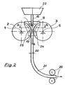
- a two-roll caster 1 as shown schematically in Fig. 1, consists of two internally cooled, driven casting rolls 2, 3, which are parallel to casting roll axes 4, 5 rotate in opposite directions and made of two made of refractory material side plates 6, 7, each embedded in a support frame 8, 9 and secured thereto.
- the Lateral surfaces 10, 11 of the casting rolls 2, 3 and the end faces 12, 13 of the side plates 6, 7 Together form a closed in the circumferential direction melt pool 14, the supplied by a Tauchg tellrohr 15 superheated molten metal 16 receives.
- the casting roll 2 is rotatably fixed in a supporting frame, not shown, via supporting bearings supported
- the casting roll 3 is in the support frame, not shown, with respect to the first Casting roller 2 supported displaceable parallel, as indicated by the double arrow.
- a selectable casting gap 19th adjustable which corresponds to the thickness 20 of the cast metal strip 21 ( Figure 2).
- Fig. 3 the positioning of a side plate 6 at the end faces 12, 13 of the casting rolls 2, 3 is shown in an initial phase of the casting process with a new side plate made of refractory material.
- the melt pool 14 is filled with molten metal 16, and strand shells 23, 24 have formed on the lateral surfaces 10, 11 of the casting rolls 2, 3.
- the side plate 6 is formed by horizontal forces F h on the support frame 8 of the side plate 6 parallel to the casting roll axes 4, Attack 5, sealing against the end face 12 of the casting roll 2 employed and moved in the effective direction of the horizontal forces F h within a certain time interval .DELTA.t 1 .
- a vertical force F v in the casting direction, with which the side plate 6 is moved to the casting gap 19 within this time interval.
- a state image which is determined primarily by the predetermined by the Anstellterrorismen wear of the refractory material on the end faces 12, 13 and on the lateral surfaces 10, 11 of the casting rolls 2, 3.
- This state image is shown in FIG. 4.
- the sealing surfaces 31, 32, 33, 34 and projecting into the Schmeizenpool 14 part of the side plate end face 12 contribute significantly to the improvement of the strip edges of the cast metal strip and to extend the soplattenstandzeit.
- the metal surface 16 exposed end face 12 of the side plate 6 wears due to systemic chemical and mechanical erosion or corrosion.
- the Side plate 6 is in a support frame 8, permitting thermal expansion, yielding clamped.
- To preheat the side plates to operating temperature are on the back of the side panels in a space not shown heaters provided either by gas burners or by electric heaters, such as For example, induction heaters are formed. This will make a sudden, locally high thermal load of side plates minimized.
- the support frame 8 is on an L-shaped adjustment frame 37 along vertical guides 38 in the casting direction vertically guided and movable by a VertikalverstellISS 39, the support frame 8 and articulated on the adjusting frame 37.
- the adjusting frame 37 is in turn on a stationary base frame 40 supported and by horizontal guides 41 opposite arranged horizontally in the direction of the casting roll axis 4 Agebar.
- the Horizontal adjustment 42 is on the one hand on the base frame 40 and on the other hand on Versteltrahmen 37 hinged.
- the Vertikalverstell responded 39 and the Horizontal adjustment 42 allow a controlled or regulated Anstell- and Return movement of the side plates realized by various adjusting devices can be, such as by springs.
- these drive systems are with Trackers coupled and allow precise adjustment of Positions and feed movements, based on default values, such as contact pressure, Feed rate, etc., as a time function of a control, or Control system can be specified.
- This lapping phase should, if it is necessary at all, not longer than 120 sec with mean side panel wear at least 10 mm / h, preferably at least 20 mm / h. However, this value may be only briefly before Stopper opening reached.
- the actual casting process begins with a first time interval .DELTA.t 1 , in the course of which a horizontal movement of the side plates, in the direction of G manwalzenachsen on the front sides of the casting rolls, takes place in three sections.
- a starting phase (1st section)
- the side plates are moved against the end faces of the casting rolls for a maximum period of 90 seconds with a wear or feed rate v s1 of 1.0 mm / h to 20 mm / h.
- This start phase lasts at most 90 sec.
- this start phase preferably at the beginning of the plug opening and the melt pool begins to fill with molten metal, wherein at the stopper opening and shortly thereafter a maximum value for the feed rate of 50 mm / h is not exceeded.
- transition phase (section 2) lasting a maximum of 120 seconds during which the feed rate v s2 of the side plates is less than 10 mm / h and which leads to a stationary operating phase (section 3) in which the feed rate v s3 to values of 0.2 mm / h to 4.0 mm / h.
- a transition phase (section 2) lasting a maximum of 120 seconds during which the feed rate v s2 of the side plates is less than 10 mm / h and which leads to a stationary operating phase (section 3) in which the feed rate v s3 to values of 0.2 mm / h to 4.0 mm / h.
- a second time interval .DELTA.t 2 in which a vertical, thus oriented in the casting direction G feed movement of the side plates begins.
- the feed rate v v1 is about 4.0 to 10.0 mm / h in undisturbed stationary casting operation, but may also be in a wider range from 2.0 to 20 mm / h.
- This vertical feed motion can also be dependent on interference, if tape edge phenomena or wear, force or motion signals of the side plates indicate disturbances of the stationary wear process.
- the vertical feed movement of the side plates is performed stepwise, ie after a rapid feed movement with a feed rate v v2 from 2.0 to 20 mm / h over a distance of 0.2 to 2.0 mm follows a Standstill phase of up to 30 min, before recently a feed movement is initiated.
- This intermittent feed movement is sufficient to produce in the circumferential direction a resistant sealing surface between G manwalzenMantel components and side plate, which remains erosion-stable for a long time.
- the predetermined hourly wear rates on the side plates which correspond to a feed rate (v s1 , v s2 , v s3 , v v1 , v v2 ) of the side plates, can be controlled by controlled contact pressures (p s1 , p s2 , p s3 , p v1 , p v2 ), which are applied by the horizontal and Vertikalanstellvortechnischen and transmitted to the side plates and are further controlled in a measuring and control circuit according to the predetermined for stationary conditions wear.
- the same result can be achieved by a mechanical drive in connection with, for example, a process-controlled stepper motor.
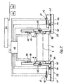
- FIG. 7 The control technique underlying the starting method according to the invention Structure of the two-roll caster is shown schematically in Fig. 7.
- Fig. 7 Starting from the in Fig. 5 already shown structural structure of the side plate support device 36 with a support frame 8, 9, which receives the side plates 6, 7, an adjustment frame 37 at the respective support frame 8, 9 is guided in vertical guides 41 and a Base frame 40, on which the adjusting frame 37 is supported in horizontal guides 41 and is guided, position detecting means 44 for determining the relative position of the respective adjustment frame 37 to the base frame 40 and position detection devices 45 for determining the relative position of the respective support frame 8, 9 to the adjustment frame 37 provided.
Landscapes
- Engineering & Computer Science (AREA)
- Mechanical Engineering (AREA)
- Continuous Casting (AREA)
Description
- einer Startphase, bei der die Seitenplatten während einer Zeitspanne von maximal 90 sec mit einer Vorschubgeschwindigkeit, die einem Materialverschleiß an den Seitenplatten von weniger als 50 mm/h, vorzugsweise von 1 mm/h bis 30 mm/h entspricht, gegen die Stirnseiten der Gießwalzen bewegt werden,
- einer Übergangsphase, bei der die Seitenplatten während einer Zeitspanne von maximal 3 min mit einer Vorschubgeschwindigkeit, die einem Materialverschleiß an den Seitenplatten von weniger als 20 mm/h entspricht, gegen die Stirnseiten der Gießwalzen bewegt werden und
- einer stationären Betriebsphase, bei der die Seitenplatten mit einer Vorschubgeschwindigkeit, die einem Materialverschleiß an den Seitenplatten zwischen 0,2 mm/h und 4 mm/h entspricht, gegen die Stirnseiten der Gießwalzen bewegt werden.
- einer Startphase, bei der die Seitenplatten während einer Zeitspanne von maximal 90 sec mit einem Anpressdruck, der einem Materialverschleiß an den Seitenplatten von weniger als 50 mm/h, vorzugsweise von 1 mm/h bis 30 mm/h entspricht, gegen die Stirnseiten der Gießwalzen gepresst werden,
- einer Übergangsphase, bei der die Seitenplatten während einer Zeitspanne von maximal 3 min mit einem Anpressdruck, der einem Materialverschleiß an den Seitenplatten von weniger als 20 mm/h entspricht, gegen die Stirnseiten der Gießwalzen gepresst werden und
- einer stationären Betriebsphase, bei der die Seitenplatten mit einem Anpressdruck, der einem Materialverschleiß an den Seitenplatten zwischen 0,2 mm/h und 4 mm/h entspricht, gegen die Stirnseiten der Gießwalzen gepresst werden.
- dass jede Seitenplatten-Trageinrichtung Horizontalführungen für die Umsetzung einer Vorschubbewegung der Seitenplatte in Richtung der Gießwalzenachsen aufweist,
- dass jeder Seitenplatten-Trageinrichtung eine Horizontalverstelleinrichtung für die horizontale Verlagerung der Seitenplatte und eine Positionserfassungseinrichtung für die Horizontalposition der Seitenplatte zugeordnet ist,
- dass jede Seitenplatten-Trageinrichtung Vertikalführungen für die Umsetzung einer Vorschubbewegung der Seitenplatte in Gießrichtung, bezogen auf den Gießspalt, autweist,
- dass jeder Seitenplatten-Trageinrichtung eine Vertikalverstelleinrichtung für die vertikale Verlagerung der Seitenplatte und eine Positionserfassungseinrichtung für die Vertikalposition der Seitenplatte zugeordnet ist,
- dass eine Recheneinheit über Signaileitungen mit den Horizontalverstelleinrichtungen, den Vertikalverstelleinrichtungen und den Positionserfassungseinrichtungen zur Übermittlung von Mess- und Steuersignalen verbunden ist.
Bei Zugrundelegung entsprechender Prozessmodelle ermöglicht dieser Anlagenaufbau einen prozessgesteuerten Ablauf der Seitenplattenanstellung entsprechend einem vorgebenen Ablaufplan unter Berücksichtigung von Eingangsbedingungen, wie Stahlqualitäten, Schmelzen- und Überhitzungstemperatur, Gießdicke, Gießgeschwindigkeit, Seitenplattenwerkstoffe etc., sowie die Berücksichtigung von aktuellen Störungen im Produktionsprozess, wie unregelmäßigen Seitenplattenverschleiß, Änderungen der Gießgeschwindigkeit und ähnlichem.
- Fig. 1
- eine Zweiwalzengießanlage zur Anwendung des erfindungsgemäßen Verfahrens,
- Fig. 2
- einen Vertikalschnitt durch die Zweiwalzengießanalge nach Fig. 1,
- Fig. 3
- die Position und den Zustand der Seitenplatte kurz nach Beginn des ersten Zeitintervalls in einem horizontal gelegten Teilschnitt durch die Zweiwalzengießanlagen entlang der Linie A - A in Fig. 2,
- Fig. 4
- die Position und den Zustand der Seitenplatte während des Gießprozesses in einer fortgeschrittenen Phase des ersten oder zweiten Zeitintervalls in einem horizontal gelegten Teilschnitt durch die Zweiwalzengießanlagen entlang der Linie A - A in Fig. 2,
- Fig. 5
- schematische Darstellung einer Seitenplatten-Tragvorrichtung,
- Fig. 6
- Ausführungsbeispiel für den zeitlichen Verlauf der Anstellbewegungen der Seitenplatten und des Seitenplattenverschleißes,
- Fig.7
- Regelschema für die erfindungsgemäße Seitenplattenanstellung.
Claims (20)
- Verfahren zur Erzeugung eines Metallbandes mit einer Zweiwalzengießeinrichtung (1), mit welchem Metallschmelze (16) in einen Schmelzenpool (14) eingebracht wird, der von zwei gegensinnig rotierenden Gießwalzen (2, 3) mit parallel zueinander angeordneten Gießwalzenachsen (4, 5) und zwei an den Stirnseiten (17, 18) der Gießwalzen anliegenden Seitenplatten (6, 7) gebildet wird und bei dem ein zumindest teilerstarrtes Metallband (21) aus einem von den Gießwalzen gebildeten Gießspalt (19) ausgefördert wird, dadurch gekennzeichnet,dass die Seitenplatten (6, 7) in einem ersten Zeitintervall (Δt1) in einer ersten Bewegungsrichtung parallel zu den Gießwalzenachsen (4, 5) gegen die Stirnseiten (17, 18) der Gießwalzen bewegt werden unddass die Seitenplatten (6, 7) in einem zweiten Zeitintervall (Δt2) in einer zweiten Bewegungsrichtung parallel zur Gießrichtung (G) im Gießspalt (19) gegen einen Abschnitt der Mantelflächen (10, 11) der Gießwalzen bewegt werden.
- Verfahren nach Anspruch 1, dadurch gekennzeichnet, dass in zeitlicher Abfolge das erste Zeitintervall (Δt1) zumindest in einem Teilabschnitt das zweite Zeitintervall (Δt2) überlagert.
- Verfahren nach Anspruch 1, dadurch gekennzeichnet, dass in zeitlicher Abfolge das zweite Zeitintervall (Δt2) zumindest in einem Teilabschnitt das erste Zeitintervall (Δt1) überlagert.
- Verfahren nach einem der vorhergehenden Ansprüche, dadurch gekennzeichnet, dass das erste Zeitintervall (Δt1) vor dem zweiten Zeitintervall (Δt2) beginnt.
- Verfahren nach einem der vorhergehenden Ansprüche, dadurch gekennzeichnet, dass das erste Zeitintervall (Δt1) mit dem Zuführen der Metallschmelze in den Schmelzenpool (14) oder vorher beginnt.
- Verfahren nach einem der vorhergehenden Ansprüche, dadurch gekennzeichnet, dass die Seitenplatten (6, 7) in Abhängigkeit von den Verschleißeigenschaften des verwendeten Feuerfest-Materials gegen die Gießwalzen (2, 3) bewegt werden.
- Verfahren nach einem der vorhergehenden Ansprüche 1 bis 6, dadurch gekennzeichnet, dass das erste Zeitintervall (Δt1) von drei Abschnitten gebildet wird,einer Startphase, bei der die Seitenplatten (6, 7) während einer Zeitspanne von maximal 90 sec mit einer Vorschubgeschwindigkeit (vs1), die einem Materialverschleiß an den Seitenplatten von weniger als 50 mm/h, vorzugsweise von 1 mm/h bis 30 mm/h entspricht, gegen die Stirnseiten (17, 18) der Gießwalzen bewegt werden,einer Übergangsphase, bei der die Seitenplatten während einer Zeitspanne von maximal 3 min mit einer Vorschubgeschwindigkeit (vs2), die einem Materialverschleiß an den Seitenplatten von weniger als 20 mm/h entspricht, gegen die Stirnseiten der Gießwalzen bewegt werden,einer stationären Betriebsphase, bei der die Seitenplatten mit einer Vorschubgeschwindigkeit (vs3), die einem Materialverschleiß an den Seitenplatten zwischen 0,2 mm/h und 4 mm/h entspricht, gegen die Stirnseiten der Gießwalzen bewegt werden.
- Verfahren nach einem der vorhergehenden Ansprüche 1 bis 6, dadurch gekennzeichnet, dass das erste Zeitintervall (Δt1) von drei Abschnitten gebildet wird,einer Startphase, bei der die Seitenplatten (6, 7) während einer Zeitspanne von maximal 90 sec mit einem Anpressdruck (ps1) der einem Materialverschleiß an den Seitenplatten von weniger als 50 mm/h, vorzugsweise von 1 mm/h bis 30 mm/h entspricht, gegen die Stirnseiten der Gießwalzen gepresst werden,einer Übergangsphase, bei der die Seitenplatten während einer Zeitspanne von maximal 3 min mit einem Anpressdruck (ps2), der einem Materialverschleiß an den Seitenplatten von weniger als 20 mm/h entspricht, gegen die Stirnseiten der Gießwalzen gepresst werden,einer stationären Betriebsphase, bei der die Seitenplatten mit einem Anpressdruck (ps3), der einem Materialverschleiß an den Seitenplatten zwischen 0,2 mm/h und 4 mm/h entspricht, gegen die Stirnseiten der Gießwalzen gepresst werden.
- Verfahren nach einem der vorhergehenden Ansprüche, dadurch gekennzeichnet, dass das zweite Zeitintervall (Δt2) spätestens 30 min, vorzugsweise bereits 10 min nach Beginn des ersten Zeitintervalls (Δt1) beginnt.
- Verfahren nach einem der vorhergehenden Ansprüche, dadurch gekennzeichnet, dass das zweite Zeitintervall (Δt2) im wesentlichen mit Beginn der stationären Betriebsphase beginnt.
- Verfahren nach einem der vorhergehenden Ansprüche, dadurch gekennzeichnet, dass die Seitenplatten während des zweiten Zeitintervalles (Δt2) mit einer Vorschubgeschwindigkeit (vv1, vv2) oder einem Anpressdruck (pv1, pv2), die/der einem Materialverschleiß an den Seitenplatten von 2 mm/h bis 20 mm/h, vorzugsweise 4,0 bis 10 mm/h, entspricht, gegen einen Abschnitt der Mantelfläche der Gießwalzen bewegt/gepresst werden.
- Verfahren nach einem der Ansprüche 1 bis 10, dadurch gekennzeichnet, dass die Seitenplatten (6, 7) während des zweiten Zeitintervalls (Δt2) intermittierend bewegt werden, wobei Bewegungsphasen und Stillstandsphasen einander abwechseln und die Stillstandphasen der Seitenplatten 30 min, vorzugsweise 5 min, nicht überschreiten.
- Verfahren nach Anspruch 12, dadurch gekennzeichnet, dass die Seitenplatten (6, 7) während jeder Bewegungsphase um 0,01 bis 2 mm, vorzugsweise 0,1 bis 1 mm, gegen einen Abschnitt der Mantelfläche (10, 11) der Gießwalzen bewegt werden.
- Verfahren nach einen der vorhergehenden Ansprüche, dadurch gekennzeichnet, dass dem ersten Zeitintervall (Δt1) eine Einschleifphase unmittelbar vorgeordnet wird, bei der die Seitenplatten während einer Zeitspanne von maximal 120 sec mit einer Vorschubgeschwindigkeit oder einem Anpressdruck, die/der einem mittleren Materialverschleiß an den Seitenplatten von mindestens 10 mm/h, vorzugsweise mindestens 20 mm/h, entspricht, gegen die Stirnseiten der Gießwalzen gepresst werden, wobei die Seitenplatten während eines Teilabschnittes dieser Einschleifphase gegebenenfalls zusätzlich mit hohem Anpressdruck in Gießrichtung gegen einen Abschnitt der Mantelflächen der Gießwalzen gepresst werden.
- Verfahren nach einem der Ansprüche 1 bis 13, dadurch gekennzeichnet, dass dem ersten Zeitintervall (Δt1) eine Einschleifphase vorgeordnet wird, bei der ein mittlerer horizontaler Materialverschleiß an den Seitenplatten von mindestens 0;3 mm erzielt wird, wobei diese Einschleifphase bei kalten oder vorgeheizten Seitenplatten erfolgt und gegebenenfalls zwischen dieser Einschleifphase und dem Beginn des ersten Zeitintervalls (Δt1) eine Zwischenerhitzung erfolgt.
- Zweiwalzengießeinrichtung mit zwei parallel zueinander angeordneten und gegensinnig rotierenden Gießwalzen (2, 3) und zwei an den Stirnseiten (17, 18) der Gießwalzen anliegenden und in Seitenplatten-Tragvorrichtungen (36) abgestützte Seitenplatten (8, 9), zur Durchführung eines Verfahrens nach einem der Ansprüche 1 bis 14, dadurch gekennzeichnet,dass jede Seitenplatten-Trageinrichtung (36) Horizontalführungen (41) für die Umsetzung einer Vorschubbewegung der Seitenplatte (8, 9) in Richtung der Gießwalzenachsen (4, 5) aufweist,dass jeder Seitenplatten-Trageinrichtung (36) eine Horizontalverstelleinrichtung (42) für die horizontale Verlagerung der Seitenplatte (8, 9) und eine Positionserfassungseinrichtung (44) für die Horizontalposition der Seitenplatte (8, 9) zugeordnet ist,dass jede Seitenplatten-Trageinrichtung (36) Vertikalführungen (38) für die Umsetzung einer Vorschubbewegung der Seitenplatte (8, 9) in Gießrichtung (G), bezogen auf den Gießspalt (19), aufweist,dass jeder Seitenplatten-Trageinrichtung (36) eine Vertikalverstelleinrichtung (39) für die vertikale Verlagerung der Seitenplatte (8, 9) und eine Positionserfassungseinrichtung (45) für die Vertikalposition der Seitenplatte zugeordnet ist,dass eine Recheneinheit (46) über Signalleitungen mit den Horizontalverstelleinrichtungen (42), den Vertikalverstelleinrichtungen (39) und den Positionserfassungseinrichtungen (44, 45) zur Übermittlung von Mess- und Steuersignalen verbunden ist.
- Zweiwalzengießeinrichtung nach Anspruch 16, dadurch gekennzeichnet, dass den Horizontalverstelleinrichtungen (42) und den Vertikalverstelleinrichtungen (39) einzelne Anpressdruck-Messeinrichtungen (47, 48) zur Ermittlung des Anpressdruckes der Seitenplatten (8, 9) an die Gießwalzen (2, 3) in horizontaler und vertikaler Richtung zugeordnet sind und die Horizontalverstelleinrichtungen (42) und die Vertikalverstelleinrichtungen (39) über Signalleitungen mit der Recheneinheit (46) verbunden sind.
- Zweiwalzengießeinrichtung nach Anspruch 17, dadurch gekennzeichnet, dass die Recheneinheit (46) als Einzelregelkreis ausgebildet ist, der ein Anlagenleitsystem (51) übergeordnet ist.
- Zweiwaizengießeinrichtung nach einem der Ansprüche 16 bis 18, dadurch gekennzeichnet, dass die Seitenplatten-Trageinrichtung (36) von einem Basisrahmen (40), einem Verstellrahmen (37) und einem Tragrahmen (8, 9) gebildet ist, wobei der Verstellrahmen (37) über Horizontalführungen (41) am Basisrahmen (40) und der Tragrahmen (8, 9) für die Seitenplatte (6, 7) über Vertikalführungen (38) am Verstellrahmen (37) abgestützt sind und die Horizontalverstelleinrichtung (42) zwischen Basisrahmen (40) und Verstellrahmen (37) und die Vertikalverstelleinrichtung (39) zwischen Verstellrahmen (37) und Tragrahmen (8, 9) für die Seitenplatte (6, 7) angeordnet sind.
- Zweiwalzengießeinrichtung nach einem der Ansprüche 16 bis 19, dadurch gekennzeichnet, dass jeder Seitenplatte (6, 7) eine Aufheizeinrichtung zugeordnet ist.
Priority Applications (1)
| Application Number | Priority Date | Filing Date | Title |
|---|---|---|---|
| AT03738063T ATE309875T1 (de) | 2002-06-25 | 2003-06-18 | Verfahren zur erzeugung eines metallbandes mit einer zweiwalzengiesseinrichtung |
Applications Claiming Priority (3)
| Application Number | Priority Date | Filing Date | Title |
|---|---|---|---|
| AT0094602A AT412195B (de) | 2002-06-25 | 2002-06-25 | Verfahren zur erzeugung eines metallbandes mit einer zweiwalzengiesseinrichtung |
| AT9462002 | 2002-06-25 | ||
| PCT/EP2003/006468 WO2004000487A1 (de) | 2002-06-25 | 2003-06-18 | Verfahren zur erzeugung eines metallbandes mit einer zweiwalzengiesseinrichtung |
Publications (2)
| Publication Number | Publication Date |
|---|---|
| EP1515813A1 EP1515813A1 (de) | 2005-03-23 |
| EP1515813B1 true EP1515813B1 (de) | 2005-11-16 |
Family
ID=29783638
Family Applications (1)
| Application Number | Title | Priority Date | Filing Date |
|---|---|---|---|
| EP03738063A Expired - Lifetime EP1515813B1 (de) | 2002-06-25 | 2003-06-18 | Verfahren zur erzeugung eines metallbandes mit einer zweiwalzengiesseinrichtung |
Country Status (9)
| Country | Link |
|---|---|
| US (1) | US7066238B2 (de) |
| EP (1) | EP1515813B1 (de) |
| KR (1) | KR101048534B1 (de) |
| CN (1) | CN1314500C (de) |
| AT (1) | AT412195B (de) |
| AU (1) | AU2003245968B2 (de) |
| DE (1) | DE50301696D1 (de) |
| MX (1) | MXPA04012842A (de) |
| WO (1) | WO2004000487A1 (de) |
Cited By (2)
| Publication number | Priority date | Publication date | Assignee | Title |
|---|---|---|---|---|
| DE102008010689A1 (de) | 2008-02-22 | 2009-09-03 | Thyssenkrupp Nirosta Gmbh | Verfahren und Zwei-Walzen-Gießmaschine zum Herstellen von aus einer Metallschmelze gegossenem Band |
| DE102008010688A1 (de) | 2008-02-22 | 2009-09-03 | Thyssenkrupp Nirosta Gmbh | Verfahren und Zwei-Walzen-Gießmaschine zum Herstellen von aus einer Metallschmelze gegossenem Band |
Families Citing this family (13)
| Publication number | Priority date | Publication date | Assignee | Title |
|---|---|---|---|---|
| EP1646464B1 (de) * | 2003-07-01 | 2006-11-29 | SMS Demag Aktiengesellschaft | Verfahren zum betrieb einer bandgiessmaschine f r die erzeug ung eines metallbandes |
| DE102005054996A1 (de) * | 2005-11-18 | 2007-05-24 | Thyssenkrupp Nirosta Gmbh | Verfahren zum Betrieb einer Zweiwalzengießmaschine zum Vergießen von Metallschmelzen zu gegossenem Band |
| US7556084B2 (en) * | 2006-03-24 | 2009-07-07 | Nucor Corporation | Long wear side dams |
| US7503375B2 (en) * | 2006-05-19 | 2009-03-17 | Nucor Corporation | Method and apparatus for continuously casting thin strip |
| JP5103916B2 (ja) * | 2007-02-01 | 2012-12-19 | 株式会社Ihi | 双ロール鋳造機の操業方法及びサイド堰支持装置 |
| DE102007041263A1 (de) * | 2007-08-30 | 2009-03-05 | Thyssenkrupp Nirosta Gmbh | Vorrichtung und Verfahren zum Gießen von Bändern aus einer Metallschmelze, insbesondere einer Stahlschmelze |
| JP5012353B2 (ja) * | 2007-09-19 | 2012-08-29 | 株式会社Ihi | 双ロール鋳造機の操業方法及びサイド堰支持装置 |
| US8251127B2 (en) | 2008-06-24 | 2012-08-28 | Nucor Corporation | Strip casting apparatus with independent delivery nozzle and side dam actuators |
| KR101044759B1 (ko) * | 2008-11-24 | 2011-06-27 | 주식회사 포스코 | 쌍롤식 박판주조 공정에서의 주조방법 |
| JP5837758B2 (ja) | 2011-04-27 | 2015-12-24 | キャストリップ・リミテッド・ライアビリティ・カンパニー | 双ロール鋳造装置及びその制御方法 |
| US10046384B2 (en) | 2015-09-30 | 2018-08-14 | Nucor Corporation | Side dam with pocket |
| JP7265654B2 (ja) | 2019-07-03 | 2023-04-26 | スペイラ ゲゼルシャフト ミット ベシュレンクテル ハフツング | ストリップ鋳造システムのためのメルト給送 |
| EP4023358A1 (de) | 2021-01-05 | 2022-07-06 | Speira GmbH | Trennmittelfreier aluminiumbandguss |
Family Cites Families (20)
| Publication number | Priority date | Publication date | Assignee | Title |
|---|---|---|---|---|
| JPS6326243A (ja) | 1986-07-17 | 1988-02-03 | Nippon Yakin Kogyo Co Ltd | 金属薄板帯の直接鋳造装置 |
| JPH0712526B2 (ja) | 1987-04-08 | 1995-02-15 | 日新製鋼株式会社 | 薄板連鋳機 |
| JPH082479B2 (ja) | 1988-07-22 | 1996-01-17 | 日新製鋼株式会社 | 薄板連鋳機 |
| JPH0787970B2 (ja) * | 1988-07-28 | 1995-09-27 | 日新製鋼株式会社 | 薄板連鋳機 |
| JPH07115133B2 (ja) * | 1988-08-08 | 1995-12-13 | 日新製鋼株式会社 | 薄板連鋳装置およびその運転方法 |
| JPH07115134B2 (ja) | 1988-09-02 | 1995-12-13 | 日新製鋼株式会社 | 薄板連鋳機 |
| FR2656244A1 (fr) * | 1989-12-26 | 1991-06-28 | Siderurgie Fse Inst Rech | Dispositif de coulee continue de produits metalliques minces entre deux cylindres refroidis en rotation. |
| JPH0741376B2 (ja) * | 1990-06-11 | 1995-05-10 | 新日本製鐵株式会社 | 薄帯連続鋳造方法 |
| JP3071294B2 (ja) | 1992-03-24 | 2000-07-31 | 日新製鋼株式会社 | 薄板連鋳装置 |
| FR2703935B1 (fr) * | 1993-04-14 | 1995-07-21 | Usinor Sacilor | Dispositif de changement rapide et de maintien d'une paroi laterale d'une machine de coulee continue d'un produit metallique entre cylindres. |
| JPH06326243A (ja) * | 1993-05-13 | 1994-11-25 | Dainippon Printing Co Ltd | 樹脂モールド型半導体装置用リードフレーム部材の製造方法 |
| FR2727337B1 (fr) * | 1994-11-30 | 1996-12-27 | Usinor Sacilor | Dispositif de support d'une face laterale d'une installation de coulee continue de bandes metalliques entre cylindres |
| GB2296883B (en) * | 1995-01-12 | 1998-10-14 | Ishikawajima Harima Heavy Ind | Strip casting |
| IT1284201B1 (it) * | 1996-07-31 | 1998-05-08 | Sviluppo Materiali Spa | Piastre con riporti ceramici antiusura per macchine per colata conntinua di corpi piani sottili e procedimento per la loro |
| FR2765504B1 (fr) * | 1997-07-04 | 1999-08-20 | Usinor | Face laterale d'obturation de l'espace de coulee d'une installation de coulee continue entre cylindres de bandes minces metalliques |
| FR2768354B1 (fr) * | 1997-09-12 | 1999-10-22 | Usinor | Face laterale pour l'obturation de l'espace de coulee d'une installation de coulee continue de bandes metalliques entre cylindres, et installation de coulee ainsi equipee |
| KR100333070B1 (ko) * | 1997-12-20 | 2002-10-18 | 주식회사 포스코 | 쌍롤식박판주조장치에서의에지댐위치제어방법 |
| JP2000042692A (ja) | 1998-07-27 | 2000-02-15 | Nippon Steel Corp | 双ドラム式連続鋳造方法及び装置 |
| FR2786716B1 (fr) * | 1998-12-03 | 2001-01-05 | Usinor | Dispositif d'application d'une face laterale d'installation de coulee continue de bandes metalliques entre deux cylindres contre les faces planes des cylindres |
| DE10056916A1 (de) | 2000-11-16 | 2002-05-23 | Sms Demag Ag | Verfahren zum Stranggießen eines Metallbandes |
-
2002
- 2002-06-25 AT AT0094602A patent/AT412195B/de not_active IP Right Cessation
-
2003
- 2003-06-18 WO PCT/EP2003/006468 patent/WO2004000487A1/de not_active Ceased
- 2003-06-18 DE DE50301696T patent/DE50301696D1/de not_active Expired - Lifetime
- 2003-06-18 EP EP03738063A patent/EP1515813B1/de not_active Expired - Lifetime
- 2003-06-18 MX MXPA04012842A patent/MXPA04012842A/es active IP Right Grant
- 2003-06-18 US US10/519,512 patent/US7066238B2/en not_active Expired - Lifetime
- 2003-06-18 CN CNB038150166A patent/CN1314500C/zh not_active Expired - Lifetime
- 2003-06-18 AU AU2003245968A patent/AU2003245968B2/en not_active Ceased
- 2003-06-18 KR KR1020047021143A patent/KR101048534B1/ko not_active Expired - Fee Related
Cited By (4)
| Publication number | Priority date | Publication date | Assignee | Title |
|---|---|---|---|---|
| DE102008010689A1 (de) | 2008-02-22 | 2009-09-03 | Thyssenkrupp Nirosta Gmbh | Verfahren und Zwei-Walzen-Gießmaschine zum Herstellen von aus einer Metallschmelze gegossenem Band |
| DE102008010688A1 (de) | 2008-02-22 | 2009-09-03 | Thyssenkrupp Nirosta Gmbh | Verfahren und Zwei-Walzen-Gießmaschine zum Herstellen von aus einer Metallschmelze gegossenem Band |
| DE102008010689B4 (de) | 2008-02-22 | 2018-10-31 | Outokumpu Nirosta Gmbh | Zwei-Walzen-Gießmaschine zum Herstellen von aus einer Metallschmelze gegossenem Band |
| DE102008010688B4 (de) * | 2008-02-22 | 2019-03-28 | Outokumpu Nirosta Gmbh | Verfahren und Zwei-Walzen-Gießmaschine zum Herstellen von aus einer Metallschmelze gegossenem Band |
Also Published As
| Publication number | Publication date |
|---|---|
| CN1662323A (zh) | 2005-08-31 |
| AT412195B (de) | 2004-11-25 |
| US7066238B2 (en) | 2006-06-27 |
| AU2003245968A1 (en) | 2004-01-06 |
| US20060054298A1 (en) | 2006-03-16 |
| CN1314500C (zh) | 2007-05-09 |
| MXPA04012842A (es) | 2005-03-31 |
| KR20050008854A (ko) | 2005-01-21 |
| AU2003245968B2 (en) | 2008-02-21 |
| EP1515813A1 (de) | 2005-03-23 |
| WO2004000487A1 (de) | 2003-12-31 |
| ATA9462002A (de) | 2004-04-15 |
| KR101048534B1 (ko) | 2011-07-11 |
| DE50301696D1 (de) | 2005-12-22 |
Similar Documents
| Publication | Publication Date | Title |
|---|---|---|
| AT412195B (de) | Verfahren zur erzeugung eines metallbandes mit einer zweiwalzengiesseinrichtung | |
| DE69507092T2 (de) | Doppelroll Stanggiessmaschine mit angedrückten Seitenwände | |
| DE60030331T2 (de) | Bandgiessen | |
| EP0371281B1 (de) | Anlage zur Herstellung von warmgewalztem Stahlband | |
| EP1446242B1 (de) | Verfahren und vorrichtung zur kontinuierlichen herstellung eines gewalzten metallbandes aus einer metallschmelze | |
| DE69631434T2 (de) | Doppelbandstranggiessanlage und -verfahren | |
| DE3501716C2 (de) | Verfahren und Einrichtung zum Verstellen der Schmalseitenplatten einer Stranggießkokille beim Stranggießen von Metallen, insbesondere von Stahl | |
| EP3515634B1 (de) | Regelung der schmalseitenkonizität einer stranggusskokille : verfahren und vorrichtung | |
| DE60128088T2 (de) | Bandgiessmaschine | |
| EP1957220B1 (de) | Verfahren zum betrieb einer zweiwalzengiessmaschine zum vergiessen von metallschmelzen zu gegossenem band | |
| DE3880894T2 (de) | Doppelband-Giessmaschine und Verfahren zum Giessen bei Anwendung derselben. | |
| EP1225992A1 (de) | Bandgiessmaschine zur erzeugung eines metallbandes | |
| EP2436459A1 (de) | Vorrichtung und Verfahren zur Positionierung mindestens einer von zwei Gießrollen in einem kontinuierlichen Gießverfahren zur Herstellung eines Metallbands | |
| DE102008010688B4 (de) | Verfahren und Zwei-Walzen-Gießmaschine zum Herstellen von aus einer Metallschmelze gegossenem Band | |
| EP1070559B1 (de) | Verfahren zur Formatdickenänderung des Gussstranges einer Stranggiessanlage im kontinuierlichen Giessbetrieb | |
| DE102008010689A1 (de) | Verfahren und Zwei-Walzen-Gießmaschine zum Herstellen von aus einer Metallschmelze gegossenem Band | |
| EP4514554B1 (de) | Giess-walz-anlage und verfahren zur erzeugung eines stahlbandes | |
| DE102019217682A1 (de) | Vorrichtung und Verfahren zum Transportieren von Bandmaterial, insbesondere Warmband | |
| DE3317635A1 (de) | Warmwalzverfahren | |
| EP1646464B1 (de) | Verfahren zum betrieb einer bandgiessmaschine f r die erzeug ung eines metallbandes | |
| DD283961A5 (de) | Verfahren und vorrichtung zum stranggiessen duenner metallischer gegenstaende | |
| DE10134076C2 (de) | Vorrichtung zum kontinuierlichen Vergießen von Metallschmelzen, insbesondere Stahlschmelzen | |
| EP0977642A1 (de) | Verfahren zur erzeugung der oszillation einer stranggiesskokille | |
| EP0832989B1 (de) | Verfahren zur Erzeugung von beschichteten Metallsträngen, insbesondere Metallbändern und Beschichtungsanlage | |
| DE102008010653B4 (de) | Verfahren und Zwei-Walzen-Gießmaschine zum Herstellen von aus einer Metallschmelze gegossenem Band |
Legal Events
| Date | Code | Title | Description |
|---|---|---|---|
| PUAI | Public reference made under article 153(3) epc to a published international application that has entered the european phase |
Free format text: ORIGINAL CODE: 0009012 |
|
| 17P | Request for examination filed |
Effective date: 20041220 |
|
| AK | Designated contracting states |
Kind code of ref document: A1 Designated state(s): AT BE BG CH CY CZ DE DK EE ES FI FR GB GR HU IE IT LI LU MC NL PT RO SE SI SK TR |
|
| AX | Request for extension of the european patent |
Extension state: AL LT LV MK |
|
| GRAP | Despatch of communication of intention to grant a patent |
Free format text: ORIGINAL CODE: EPIDOSNIGR1 |
|
| GRAS | Grant fee paid |
Free format text: ORIGINAL CODE: EPIDOSNIGR3 |
|
| GRAA | (expected) grant |
Free format text: ORIGINAL CODE: 0009210 |
|
| DAX | Request for extension of the european patent (deleted) | ||
| AK | Designated contracting states |
Kind code of ref document: B1 Designated state(s): AT BE BG CH CY CZ DE DK EE ES FI FR GB GR HU IE IT LI LU MC NL PT RO SE SI SK TR |
|
| PG25 | Lapsed in a contracting state [announced via postgrant information from national office to epo] |
Ref country code: RO Free format text: LAPSE BECAUSE OF FAILURE TO SUBMIT A TRANSLATION OF THE DESCRIPTION OR TO PAY THE FEE WITHIN THE PRESCRIBED TIME-LIMIT Effective date: 20051116 Ref country code: SI Free format text: LAPSE BECAUSE OF FAILURE TO SUBMIT A TRANSLATION OF THE DESCRIPTION OR TO PAY THE FEE WITHIN THE PRESCRIBED TIME-LIMIT Effective date: 20051116 Ref country code: CZ Free format text: LAPSE BECAUSE OF FAILURE TO SUBMIT A TRANSLATION OF THE DESCRIPTION OR TO PAY THE FEE WITHIN THE PRESCRIBED TIME-LIMIT Effective date: 20051116 Ref country code: FI Free format text: LAPSE BECAUSE OF FAILURE TO SUBMIT A TRANSLATION OF THE DESCRIPTION OR TO PAY THE FEE WITHIN THE PRESCRIBED TIME-LIMIT Effective date: 20051116 Ref country code: SK Free format text: LAPSE BECAUSE OF FAILURE TO SUBMIT A TRANSLATION OF THE DESCRIPTION OR TO PAY THE FEE WITHIN THE PRESCRIBED TIME-LIMIT Effective date: 20051116 Ref country code: IE Free format text: LAPSE BECAUSE OF FAILURE TO SUBMIT A TRANSLATION OF THE DESCRIPTION OR TO PAY THE FEE WITHIN THE PRESCRIBED TIME-LIMIT Effective date: 20051116 |
|
| REG | Reference to a national code |
Ref country code: GB Ref legal event code: FG4D Free format text: NOT ENGLISH |
|
| REG | Reference to a national code |
Ref country code: CH Ref legal event code: EP |
|
| REF | Corresponds to: |
Ref document number: 50301696 Country of ref document: DE Date of ref document: 20051222 Kind code of ref document: P |
|
| REG | Reference to a national code |
Ref country code: IE Ref legal event code: FG4D Free format text: LANGUAGE OF EP DOCUMENT: GERMAN |
|
| PG25 | Lapsed in a contracting state [announced via postgrant information from national office to epo] |
Ref country code: DK Free format text: LAPSE BECAUSE OF FAILURE TO SUBMIT A TRANSLATION OF THE DESCRIPTION OR TO PAY THE FEE WITHIN THE PRESCRIBED TIME-LIMIT Effective date: 20060216 Ref country code: BG Free format text: LAPSE BECAUSE OF FAILURE TO SUBMIT A TRANSLATION OF THE DESCRIPTION OR TO PAY THE FEE WITHIN THE PRESCRIBED TIME-LIMIT Effective date: 20060216 Ref country code: GR Free format text: LAPSE BECAUSE OF FAILURE TO SUBMIT A TRANSLATION OF THE DESCRIPTION OR TO PAY THE FEE WITHIN THE PRESCRIBED TIME-LIMIT Effective date: 20060216 |
|
| PG25 | Lapsed in a contracting state [announced via postgrant information from national office to epo] |
Ref country code: ES Free format text: LAPSE BECAUSE OF FAILURE TO SUBMIT A TRANSLATION OF THE DESCRIPTION OR TO PAY THE FEE WITHIN THE PRESCRIBED TIME-LIMIT Effective date: 20060227 |
|
| REG | Reference to a national code |
Ref country code: SE Ref legal event code: TRGR |
|
| GBT | Gb: translation of ep patent filed (gb section 77(6)(a)/1977) |
Effective date: 20060227 |
|
| PG25 | Lapsed in a contracting state [announced via postgrant information from national office to epo] |
Ref country code: PT Free format text: LAPSE BECAUSE OF FAILURE TO SUBMIT A TRANSLATION OF THE DESCRIPTION OR TO PAY THE FEE WITHIN THE PRESCRIBED TIME-LIMIT Effective date: 20060417 |
|
| PG25 | Lapsed in a contracting state [announced via postgrant information from national office to epo] |
Ref country code: HU Free format text: LAPSE BECAUSE OF FAILURE TO SUBMIT A TRANSLATION OF THE DESCRIPTION OR TO PAY THE FEE WITHIN THE PRESCRIBED TIME-LIMIT Effective date: 20060517 |
|
| REG | Reference to a national code |
Ref country code: IE Ref legal event code: FD4D |
|
| PG25 | Lapsed in a contracting state [announced via postgrant information from national office to epo] |
Ref country code: MC Free format text: LAPSE BECAUSE OF NON-PAYMENT OF DUE FEES Effective date: 20060630 |
|
| ET | Fr: translation filed | ||
| PLBE | No opposition filed within time limit |
Free format text: ORIGINAL CODE: 0009261 |
|
| STAA | Information on the status of an ep patent application or granted ep patent |
Free format text: STATUS: NO OPPOSITION FILED WITHIN TIME LIMIT |
|
| 26N | No opposition filed |
Effective date: 20060817 |
|
| PG25 | Lapsed in a contracting state [announced via postgrant information from national office to epo] |
Ref country code: AT Free format text: LAPSE BECAUSE OF NON-PAYMENT OF DUE FEES Effective date: 20060618 |
|
| REG | Reference to a national code |
Ref country code: CH Ref legal event code: PL |
|
| PG25 | Lapsed in a contracting state [announced via postgrant information from national office to epo] |
Ref country code: LI Free format text: LAPSE BECAUSE OF NON-PAYMENT OF DUE FEES Effective date: 20070630 Ref country code: CH Free format text: LAPSE BECAUSE OF NON-PAYMENT OF DUE FEES Effective date: 20070630 |
|
| PG25 | Lapsed in a contracting state [announced via postgrant information from national office to epo] |
Ref country code: EE Free format text: LAPSE BECAUSE OF FAILURE TO SUBMIT A TRANSLATION OF THE DESCRIPTION OR TO PAY THE FEE WITHIN THE PRESCRIBED TIME-LIMIT Effective date: 20051116 |
|
| PG25 | Lapsed in a contracting state [announced via postgrant information from national office to epo] |
Ref country code: TR Free format text: LAPSE BECAUSE OF FAILURE TO SUBMIT A TRANSLATION OF THE DESCRIPTION OR TO PAY THE FEE WITHIN THE PRESCRIBED TIME-LIMIT Effective date: 20051116 |
|
| PG25 | Lapsed in a contracting state [announced via postgrant information from national office to epo] |
Ref country code: CY Free format text: LAPSE BECAUSE OF FAILURE TO SUBMIT A TRANSLATION OF THE DESCRIPTION OR TO PAY THE FEE WITHIN THE PRESCRIBED TIME-LIMIT Effective date: 20051116 |
|
| PGFP | Annual fee paid to national office [announced via postgrant information from national office to epo] |
Ref country code: LU Payment date: 20110708 Year of fee payment: 9 |
|
| PGFP | Annual fee paid to national office [announced via postgrant information from national office to epo] |
Ref country code: NL Payment date: 20120618 Year of fee payment: 10 |
|
| PGFP | Annual fee paid to national office [announced via postgrant information from national office to epo] |
Ref country code: GB Payment date: 20120618 Year of fee payment: 10 Ref country code: SE Payment date: 20120614 Year of fee payment: 10 |
|
| PGFP | Annual fee paid to national office [announced via postgrant information from national office to epo] |
Ref country code: FR Payment date: 20120711 Year of fee payment: 10 Ref country code: BE Payment date: 20120710 Year of fee payment: 10 |
|
| BERE | Be: lapsed |
Owner name: *VOEST-ALPINE INDUSTRIEANLAGENBAU G.M.B.H. & CO. Effective date: 20130630 |
|
| REG | Reference to a national code |
Ref country code: NL Ref legal event code: V1 Effective date: 20140101 |
|
| PG25 | Lapsed in a contracting state [announced via postgrant information from national office to epo] |
Ref country code: SE Free format text: LAPSE BECAUSE OF NON-PAYMENT OF DUE FEES Effective date: 20130619 |
|
| REG | Reference to a national code |
Ref country code: SE Ref legal event code: EUG |
|
| GBPC | Gb: european patent ceased through non-payment of renewal fee |
Effective date: 20130618 |
|
| REG | Reference to a national code |
Ref country code: FR Ref legal event code: ST Effective date: 20140228 |
|
| PG25 | Lapsed in a contracting state [announced via postgrant information from national office to epo] |
Ref country code: BE Free format text: LAPSE BECAUSE OF NON-PAYMENT OF DUE FEES Effective date: 20130630 |
|
| PG25 | Lapsed in a contracting state [announced via postgrant information from national office to epo] |
Ref country code: GB Free format text: LAPSE BECAUSE OF NON-PAYMENT OF DUE FEES Effective date: 20130618 Ref country code: NL Free format text: LAPSE BECAUSE OF NON-PAYMENT OF DUE FEES Effective date: 20140101 |
|
| PG25 | Lapsed in a contracting state [announced via postgrant information from national office to epo] |
Ref country code: FR Free format text: LAPSE BECAUSE OF NON-PAYMENT OF DUE FEES Effective date: 20130701 Ref country code: IT Free format text: LAPSE BECAUSE OF NON-PAYMENT OF DUE FEES Effective date: 20130618 |
|
| PGFP | Annual fee paid to national office [announced via postgrant information from national office to epo] |
Ref country code: IT Payment date: 20140627 Year of fee payment: 11 |
|
| PGRI | Patent reinstated in contracting state [announced from national office to epo] |
Ref country code: IT Effective date: 20140701 |
|
| PGRI | Patent reinstated in contracting state [announced from national office to epo] |
Ref country code: IT Effective date: 20140701 |
|
| PG25 | Lapsed in a contracting state [announced via postgrant information from national office to epo] |
Ref country code: LU Free format text: LAPSE BECAUSE OF NON-PAYMENT OF DUE FEES Effective date: 20130618 |
|
| PGFP | Annual fee paid to national office [announced via postgrant information from national office to epo] |
Ref country code: DE Payment date: 20200618 Year of fee payment: 18 |
|
| REG | Reference to a national code |
Ref country code: DE Ref legal event code: R119 Ref document number: 50301696 Country of ref document: DE |
|
| PG25 | Lapsed in a contracting state [announced via postgrant information from national office to epo] |
Ref country code: DE Free format text: LAPSE BECAUSE OF NON-PAYMENT OF DUE FEES Effective date: 20220101 |