EP1515095B1 - Section interieure pour conditionneur d'air - Google Patents
Section interieure pour conditionneur d'air Download PDFInfo
- Publication number
- EP1515095B1 EP1515095B1 EP03721034A EP03721034A EP1515095B1 EP 1515095 B1 EP1515095 B1 EP 1515095B1 EP 03721034 A EP03721034 A EP 03721034A EP 03721034 A EP03721034 A EP 03721034A EP 1515095 B1 EP1515095 B1 EP 1515095B1
- Authority
- EP
- European Patent Office
- Prior art keywords
- heat exchanger
- indoor unit
- side heat
- space
- refrigerant
- Prior art date
- Legal status (The legal status is an assumption and is not a legal conclusion. Google has not performed a legal analysis and makes no representation as to the accuracy of the status listed.)
- Expired - Lifetime
Links
- 239000003507 refrigerant Substances 0.000 claims abstract description 52
- 230000005494 condensation Effects 0.000 claims abstract description 3
- 238000009833 condensation Methods 0.000 claims abstract description 3
- 238000005192 partition Methods 0.000 claims description 34
- XLYOFNOQVPJJNP-UHFFFAOYSA-N water Substances O XLYOFNOQVPJJNP-UHFFFAOYSA-N 0.000 claims description 14
- 239000002184 metal Substances 0.000 claims description 11
- 230000001143 conditioned effect Effects 0.000 claims 1
- 230000002159 abnormal effect Effects 0.000 description 8
- 230000005540 biological transmission Effects 0.000 description 2
- 239000000470 constituent Substances 0.000 description 2
- 230000000694 effects Effects 0.000 description 2
- 239000007788 liquid Substances 0.000 description 2
- 239000011347 resin Substances 0.000 description 2
- 229920005989 resin Polymers 0.000 description 2
- 238000007664 blowing Methods 0.000 description 1
- 238000004140 cleaning Methods 0.000 description 1
- 230000001419 dependent effect Effects 0.000 description 1
- 239000000203 mixture Substances 0.000 description 1
- 210000004243 sweat Anatomy 0.000 description 1
Images


Classifications
-
- F—MECHANICAL ENGINEERING; LIGHTING; HEATING; WEAPONS; BLASTING
- F24—HEATING; RANGES; VENTILATING
- F24F—AIR-CONDITIONING; AIR-HUMIDIFICATION; VENTILATION; USE OF AIR CURRENTS FOR SCREENING
- F24F13/00—Details common to, or for air-conditioning, air-humidification, ventilation or use of air currents for screening
- F24F13/24—Means for preventing or suppressing noise
-
- F—MECHANICAL ENGINEERING; LIGHTING; HEATING; WEAPONS; BLASTING
- F24—HEATING; RANGES; VENTILATING
- F24F—AIR-CONDITIONING; AIR-HUMIDIFICATION; VENTILATION; USE OF AIR CURRENTS FOR SCREENING
- F24F1/00—Room units for air-conditioning, e.g. separate or self-contained units or units receiving primary air from a central station
- F24F1/0007—Indoor units, e.g. fan coil units
- F24F1/0059—Indoor units, e.g. fan coil units characterised by heat exchangers
-
- F—MECHANICAL ENGINEERING; LIGHTING; HEATING; WEAPONS; BLASTING
- F24—HEATING; RANGES; VENTILATING
- F24F—AIR-CONDITIONING; AIR-HUMIDIFICATION; VENTILATION; USE OF AIR CURRENTS FOR SCREENING
- F24F1/00—Room units for air-conditioning, e.g. separate or self-contained units or units receiving primary air from a central station
- F24F1/0007—Indoor units, e.g. fan coil units
- F24F1/0043—Indoor units, e.g. fan coil units characterised by mounting arrangements
- F24F1/0057—Indoor units, e.g. fan coil units characterised by mounting arrangements mounted in or on a wall
-
- F—MECHANICAL ENGINEERING; LIGHTING; HEATING; WEAPONS; BLASTING
- F24—HEATING; RANGES; VENTILATING
- F24F—AIR-CONDITIONING; AIR-HUMIDIFICATION; VENTILATION; USE OF AIR CURRENTS FOR SCREENING
- F24F1/00—Room units for air-conditioning, e.g. separate or self-contained units or units receiving primary air from a central station
- F24F1/0007—Indoor units, e.g. fan coil units
- F24F1/0068—Indoor units, e.g. fan coil units characterised by the arrangement of refrigerant piping outside the heat exchanger within the unit casing
-
- F—MECHANICAL ENGINEERING; LIGHTING; HEATING; WEAPONS; BLASTING
- F24—HEATING; RANGES; VENTILATING
- F24F—AIR-CONDITIONING; AIR-HUMIDIFICATION; VENTILATION; USE OF AIR CURRENTS FOR SCREENING
- F24F13/00—Details common to, or for air-conditioning, air-humidification, ventilation or use of air currents for screening
- F24F13/30—Arrangement or mounting of heat-exchangers
-
- F—MECHANICAL ENGINEERING; LIGHTING; HEATING; WEAPONS; BLASTING
- F24—HEATING; RANGES; VENTILATING
- F24F—AIR-CONDITIONING; AIR-HUMIDIFICATION; VENTILATION; USE OF AIR CURRENTS FOR SCREENING
- F24F1/00—Room units for air-conditioning, e.g. separate or self-contained units or units receiving primary air from a central station
- F24F1/0007—Indoor units, e.g. fan coil units
- F24F1/0018—Indoor units, e.g. fan coil units characterised by fans
- F24F1/0025—Cross-flow or tangential fans
Definitions
- the present invention relates to an indoor unit of an air conditioner, and more particularly relates to an indoor unit of an air conditioner comprising a heat exchanger and refrigerant circuit parts, and that air conditions by condensation and expansion of the refrigerant.
- separate-type air conditioners that are divided into an indoor unit and an outdoor unit
- a multi-split type air conditioner that connects a plurality of indoor units in parallel to one outdoor unit.
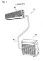
- FIG. 1 shows an exterior view of a pair type air conditioner.
- an air conditioner 81 shown therein there is a correspondence of one indoor unit 83 for one outdoor unit 82, and both 82, 83 are connected by a connecting part 89 comprising refrigerant piping, a transmission line, and the like.
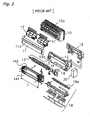
- the indoor unit of the pair type air conditioner comprises a fan rotor 3, a heat exchanger 4, an electrical equipment box 30, and the like. These constituent parts are arranged inside a casing comprising a front surface grille assembly 10, a front surface panel 11, a bottom frame 12, and the like.
- the bottom frame 12 is fixed to an indoor wall and the like by mounting it to a mounting plate 15 fixed to an indoor wall surface.
- An upper inlet 10a having slits is provided in the upper surface of the front surface grille assembly 10, and a front surface inlet 11a is also provided at the top and sides of the front surface panel 11.
- Air cleaning air filters 17 are arranged on the inside of these inlets 10a,11 a.
- an outlet for blowing out the airflow generated by the fan rotor 3 is formed at the front bottom part of the front surface grille assembly 10.
- the fan rotor 3 is arranged in a fan housing part 12a formed in the bottom frame 12, with one end being attached to the bottom frame 12 via a bearing 13, and the other end being coupled to the rotational shaft of a motor 14.
- This motor 14 is fixed to the bottom frame 12 by a motor fixed member 16.
- the heat exchanger 4 is provided so that it surrounds the front, upper, and rear upper parts of the fan rotor 3, and is also split into a front side heat exchanger 141 and a rear side heat exchanger 142, each having an effective length L.
- a front side heat exchanger 141 and a rear side heat exchanger 142 each having an effective length L.
- numerous heat radiating fins are attached to a heat transfer pipe bent a plurality of times at both the left and right ends, the air sucked in from the upper inlet 10a and the front surface inlet 11 a by the drive of the fan rotor 3 is made to pass through to the fan rotor 3 side, and heat is exchanged between the air and the refrigerant that passes through the inside of the heat transfer pipe.
- the heat exchanger 4 is connected via the refrigerant piping to the refrigerant piping from the outdoor unit.
- a drain pan assembly 18 that includes a front drain pan, a vane for adjusting the direction of the blown out air, and the like.
- the effective length of a front side heat exchanger and a rear side heat exchanger of a heat exchanger may not necessarily be the same.
- the indoor unit of the above pair type air conditioner as shown in FIG. 1 and FIG. 2 and the indoor unit employed by a multi-split type air conditioner that connects a plurality of indoor units in parallel to one outdoor unit were conventionally designed separately. Given this situation, attempts are recently being made to standardize parts between pair type indoor units and multi-split type indoor units. Although the specifications for the heat exchanger often differ between a pair type and a multi-split type, the standardization of the casing parts and the like is conceivable.
- the indoor unit of a multi-split type air conditioner is often internally provided with a motor operated valve because the plurality of indoor units are separately started and stopped, and controlled.
- This motor operated valve serves the role of adjusting the amount of refrigerant flowing in the heat exchanger of the indoor unit, and generates a relatively loud noise, such as when the refrigerant expands in the liquid-gas mixture state.
- a noise source of the motor operated valve and the like which are parts inherent to the multi-split type indoor unit, is arranged inside a regular pair type casing
- the refrigerant piping bank in the pair type indoor unit is arranged in the space on the side of the centrally disposed heat exchanger.
- the abnormal noise will cease if it is a pair type indoor unit, although it is assumed that abnormal noise from the motor operated valve and the like will leak out into the room if it is a multi-split type indoor unit.
- JP-A-09-280597 discloses to cover refrigerant circuit parts with a sound proofing plate fixed to a heat exchanger and a water pan.
- An indoor unit of an air conditioner according to the invention comprises the features of claims 1.
- the present invention herein is constituted so that the effective length of the rear side heat exchanger is less than the effective length of the front side heat exchanger, and a prescribed space is created on the backside of the indoor unit. Furthermore, refrigerant circuit parts, such as the motor operated valve and the distributor that generate relatively loud sounds when changing the flow of the refrigerant, are arranged in that space. Thus, because the refrigerant circuit parts that constitute noise sources herein are arranged in the space on the backside inside the indoor unit, the amount of sound leaking out to the front side of the indoor unit is reduced, thus suppressing discomfort to people in the room.
- the indoor unit is constituted so that the effective length of the rear side heat exchanger is less than the effective length of the front side heat exchanger, then the length of the fan rotor is matched to the front side heat exchanger, whose effective length would normally be thought to be long. Consequently, the abovementioned space (space created by the difference in the effective lengths of the front side heat exchanger and the rear side heat exchanger) is contiguous to a part of the fan rotor. In this case, even if nothing is provided between that space and the fan rotor, there is a risk that air will flow from the abovementioned space directly into the fan rotor without passing through the heat exchanger.
- the partition plates are arranged between the space, wherein the refrigerant circuit parts are arranged, and the fan rotor, the problem of air flowing into the fan rotor without passing by the indoor heat exchanger is suppressed.
- the indoor unit of the air conditioner may be the indoor unit of an air conditioner comprising an outdoor unit and a plurality of indoor units.
- the refrigerant circuit parts arranged in the space, created because the effective length of the rear side heat exchanger is less than the front side heat exchanger, includes at least a motor-operated valve.
- the motor operated valve is provided for adjusting the amount of refrigerant flowing to the plurality of indoor units.
- the motor operated valve which is usually built into the indoor unit of a multi-split type air conditioner, is arranged in the space on the backside inside the indoor unit, which easily confines noise.
- the motor operated valve sometimes generates a relatively loud abnormal sound when adjusting the amount of refrigerant; however, because it is arranged herein in the abovementioned space, which tends not to leak sound out of the indoor unit, a loud abnormal sound is no longer heard by people in the room.
- the indoor unit may further comprise a metal member that covers the space wherein the refrigerant circuit parts are arranged.
- the space is further covered by a metal member. Accordingly, even in a case where a loud abnormal noise generated from the refrigerant circuit parts passes through the casing, which is usually made of resin, and leaks out of the indoor unit, the leakage of that abnormal noise out of the indoor unit can be suppressed by the noise insulating effect of the metal member.
- the indoor unit may further comprise a drain pan that receives drain water falling from the heat exchanger. Further, the lower ends of the (partition plates) windbreaking members extend to the drain pan.
- This drain pan is arranged below the lower end of the front side heat exchanger and below the lower end of the rear side heat exchanger, and receives the drain water; it is also widely used in conventional indoor units.
- An indoor unit of an air conditioner according to one embodiment of the present invention is used in a multi-split type air conditioner, as shown in FIG. 3 .
- a multi-split type air conditioner 91 a plurality of indoor units 93 - 96 are connected to one outdoor unit 92.
- the outdoor unit 92 and the indoor units 93 - 96 are connected by connecting parts 99a - 99d comprising refrigerant piping and a transmission line.
- Four indoor units 93 - 96 are respectively arranged in separate rooms in, for example, a home, a building, or a store.
- FIG. 4 depicts a refrigerant circuit 190 of the multi-split type air conditioner 91.
- the refrigerant circuit 190 comprises one outdoor unit 92, four indoor units 93 - 96 connected in parallel to the outdoor unit 92, and refrigerant piping.
- the outdoor unit 92 comprises a compressor 20, a four-way switching valve 21, an outdoor heat exchanger 22, an accumulator 23, and the like.
- a discharge pipe thermistor 24 is attached to the discharge side of the compressor 20 for detecting the discharge pipe temperature on the discharge side of the compressor 20.
- the outdoor unit 92 is provided with an outside air thermistor 25 for detecting the outside air temperature, and an outdoor heat exchange thermistor 26 for detecting the temperature of the outdoor heat exchanger 22.
- Each of the indoor units 93 - 96 has the same constitution. The following explains the indoor units 93 - 96 using the indoor unit 93 as an example.
- the indoor unit 93 comprises an indoor heat exchanger 4a and a motor-operated valve (expansion valve) 33a mutually connected in series.
- the motor-operated valve 33a is provided on the refrigerant exit side of the indoor heat exchanger 4a and adjusts the amount of refrigerant flowing to the indoor heat exchanger 4a.
- the indoor unit 93 respectively comprises a room temperature thermistor 31 a for detecting the indoor temperature, and an indoor heat exchange thermistor 32a for detecting the temperature of the indoor heat exchanger 4a.
- a liquid pipe thermistor 34a for detecting the liquid pipe temperature between the indoor heat exchanger 4a and the motor-operated valve 33a is provided in the piping between the indoor heat exchanger 4a and the motor-operated valve 33a.
- a gas pipe thermistor 35a is provided on the gas pipe side (refrigerant entrance side) of the indoor heat exchanger 4a for detecting the refrigerant temperature passing therethrough internally.
- the other indoor units 94, 95, 96 are likewise constituted the same as the indoor unit 93, and their indoor heat exchangers, motor operated valves, and various thermistors are assigned equivalent symbols in FIG. 4 .
- the indoor units 93 - 96 used in the multi-split type air conditioner 91 have built-in motor-operated valves 33a - 33d.
- the following explains the indoor unit used in the multi-split type air conditioner, using the indoor unit 93 as an example, and focusing on the arrangement of the parts.
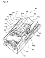
- the indoor heat exchanger 4a that partially covers the front, upper, and rear parts of a fan rotor 3 principally comprises a front side heat exchanger 41 and a rear side heat exchanger 42, as shown in FIG. 5 and FIG. 6 .
- the rear side heat exchanger 42 has an effective length that is less than the front side heat exchanger 41, and an end part 42b on a motor 14 side thereof is positioned closer to the central portion in the latitudinal direction of the indoor unit 93 than an end part 41b of the front side heat exchanger 41 (refer to FIG. 5 ).
- a relatively large space SP is ensured on the outer side of the rear side heat exchanger 42 (the side on the motor 14 side).
- the width dimension of this space SP is substantially the same dimension as the difference in the effective lengths of the front side heat exchanger 41 and the rear side heat exchanger 42, and is 100 - 150 mm.
- a structure is employed in the indoor unit 93 wherein an upper end 41 a of the front side heat exchanger 41 is slightly spaced apart from an upper end 42a of the rear side heat exchanger 42, and a connecting plate 43 extends therebetween.
- This connecting plate 43 integrates the front side heat exchanger 41 and the rear side heat exchanger 42 as the indoor heat exchanger 4a, and serves the role of preventing the unfortunate passage of the air from above the indoor heat exchanger 4a to the fan rotor 3 below without passing through the front side heat exchanger 41, the rear side heat exchanger 42, and the like.
- the motor-operated valve 33a in the indoor unit 93, the motor-operated valve 33a, refrigerant piping 133 that connects to the motor-operated valve 33a, and a distributor 39 that divides the flow of refrigerant exiting the motor-operated valve 33a to each of the heat transfer passageways of the indoor heat exchanger 4a, and the like, are arranged in the space SP created by the difference in the effective lengths of the front side heat exchanger 41 and the rear side heat exchanger 42. As shown in FIG. 5 , the motor-operated valve 33a is arranged laterally to improve maintainability.
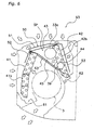
- the space SP is enclosed by a metal cover 50, a vertical partition plate 44, and a lateral partition plate 45.
- the metal cover 50 is a plate member integrally formed from a first cover part 51 that covers the upper part of the space SP, a second cover part 52 that extends downward diagonally from the front end of the first cover part 51 along the front surface of the front side heat exchanger 41, and a third cover part 53 that extends downward diagonally from the rear end of the first cover part 51 and covers the rear of the space SP.
- This metal cover 50 is provided principally for the purpose of isolating noise.
- the vertical partition plate 44 and the lateral partition plate 45 are plate-shaped members made of metal and provided to prevent the leakage of air that flows into the space SP out to the fan rotor side.
- the vertical partition plate 44 is positioned above the fan rotor 3, and partitions the space surrounding the fan rotor 3 and the space SP wherein the motor-operated valve 33a and the like are arranged.
- the lateral partition plate 45 is a substantially triangular member that extends perpendicularly frontward from the end part 42b on the space SP side of the rear side heat exchanger 42, and the sides abut orthogonally with the end part 42b of the rear side heat exchanger 42, the end part on the space SP side of the connecting plate 43, and the end part of the vertical partition plate 44.
- a front drain pan 61 is arranged below the lower end of the front side heat exchanger 41, and a rear drain pan 62 is arranged below the lower end of the rear side heat exchanger 42, respectively.
- These drain pans 61, 62 form a bottom frame and a drain pan assembly having a constitution the same as the conventional bottom frame 12 and drain pan assembly 18 in FIG. 2 , and serve the role of receiving the drain water that drips downward from the indoor heat exchanger 4a and the like.
- a drain route 63 is formed below the portion where the abovementioned vertical partition plate 44, the lateral partition plate 45, and the end part 42b on the space SP side of the rear side heat exchanger 42, which surround the space SP, intersect so that the drain water from that portion does not drip down to the fan rotor 3.
- This drain route 63 is structured so that a metal plate is bent at the intersecting portion of the vertical partition plate 44 and the lateral partition plate 45 (a part of the vertical partition plate 44, a part of the lateral partition plate 45, or separate members mounted to these partition plates 44, 45), and so that its cross-section is pocket-shaped.
- the drain water that drops from the end part 42b of the rear side heat exchanger 42 along the lateral partition plate 45, and the drain water that sweats out from the intersecting portion of the vertical partition plate 44 and the lateral partition plate 45 to the fan rotor 3 side along a gap from the space SP due to the pressure differential are guided to the drain route 63 and flow into the rear drain pan 62 (refer to FIG. 6 ).
- the heat exchanger unit reduces the amount of noise leaking out to the front side of the indoor unit and suppresses discomfort to people in the room because the effective length of the rear side heat exchanger is less than the effective length of the front side heat exchanger, a prescribed space is created on the back side of the indoor unit, and the refrigerant circuit parts, such as the motor operated valve and the distributor, which generate a relatively loud sound when changing the flow of the refrigerant, are arranged in that space.
Landscapes
- Engineering & Computer Science (AREA)
- Chemical & Material Sciences (AREA)
- Combustion & Propulsion (AREA)
- Mechanical Engineering (AREA)
- General Engineering & Computer Science (AREA)
- Physics & Mathematics (AREA)
- Thermal Sciences (AREA)
- Air Filters, Heat-Exchange Apparatuses, And Housings Of Air-Conditioning Units (AREA)
- Air-Conditioning Room Units, And Self-Contained Units In General (AREA)
- Devices For Blowing Cold Air, Devices For Blowing Warm Air, And Means For Preventing Water Condensation In Air Conditioning Units (AREA)
- Air Conditioning Control Device (AREA)
Claims (5)
- Unité intérieure d'un climatiseur qui conditionne l'air par condensation et expansion d'un réfrigérant, comprenant :un échangeur de chaleur (4a) comprenant un côté avant d'échangeur de chaleur (41) et un côté arrière échangeur de chaleur (42), et qui échange de la chaleur entre un réfrigérant et l'air ; etdes parties de circuit de réfrigérant (33a, 39) qui modifient le débit dudit réfrigérant :un rotor de ventilateur (3) pour envoyer l'air conditionné à l'intérieur ;dans lequel,ledit côté arrière d'échangeur de chaleur (42) a une longueur efficace plus faible que ledit côté avant d'échangeur de chaleur (41) ; etlesdites parties de circuit de réfrigérant (33a, 39) sont agencées dans un espace (SP) créé par la différence de longueur efficace entre ledit côté avant d'échangeur de chaleur (41) et ledit côté arrière d'échangeur de chaleur (42), caractérisée par des plaques de séparation (44, 45) agencées entre ledit espace (SP) et ledit rotor de ventilateur (3), supprimant l'écoulement d'air depuis ledit espace (SP) directement dans ledit rotor de ventilateur (3) sans traverser l'échangeur de chaleur (4).
- Unité intérieure de climatiseur selon la revendication 1, comprenant en outre :un élément métallique (50) qui couvre ledit espace (SP).
- Unité intérieure de climatiseur selon la revendication 1 ou la revendication 2, dans laquelle lesdites plaques de séparation comprennent une plaque de séparation verticale (44) positionnée au-dessus du rotor de ventilateur (3) et une plaque de séparation latérale (45) étant un élément sensiblement triangulaire s'étendant perpendiculairement vers l'avant depuis une partie d'extrémité (42b) dudit espace (SP) à côté dudit côté arrière d'échangeur de chaleur (42).
- Unité intérieure du climatiseur selon l'une quelconque des revendications précédentes, comprenant en outre :un plateau de drainage (62) qui reçoit l'eau de drainage tombant dudit échangeur de chaleur (4a) ;dans lequel,les extrémités inférieures desdites plaques de séparation (44, 45) s'étendent audit plateau de drainage (62).
- Climatiseur comprenant une unité extérieure (92) et une pluralité d'unités intérieures (93 - 96) selon l'une quelconque des revendications précédentes, dans lequel
lesdites parties de circuit de réfrigérant agencées dans ledit espace (SP) comprennent au moins une vanne motorisée (33a) pour ajuster la quantité de réfrigérant s'écoulant vers ladite pluralité d'unités intérieures (93 - 96).
Applications Claiming Priority (3)
| Application Number | Priority Date | Filing Date | Title |
|---|---|---|---|
| JP2002139745A JP3731067B2 (ja) | 2002-05-15 | 2002-05-15 | 空気調和装置の室内機 |
| JP2002139745 | 2002-05-15 | ||
| PCT/JP2003/005671 WO2003098119A1 (fr) | 2002-05-15 | 2003-05-06 | Section interieure pour conditionneur d'air |
Publications (3)
| Publication Number | Publication Date |
|---|---|
| EP1515095A1 EP1515095A1 (fr) | 2005-03-16 |
| EP1515095A4 EP1515095A4 (fr) | 2010-07-14 |
| EP1515095B1 true EP1515095B1 (fr) | 2011-10-26 |
Family
ID=29544903
Family Applications (1)
| Application Number | Title | Priority Date | Filing Date |
|---|---|---|---|
| EP03721034A Expired - Lifetime EP1515095B1 (fr) | 2002-05-15 | 2003-05-06 | Section interieure pour conditionneur d'air |
Country Status (8)
| Country | Link |
|---|---|
| EP (1) | EP1515095B1 (fr) |
| JP (1) | JP3731067B2 (fr) |
| KR (1) | KR100605844B1 (fr) |
| CN (2) | CN1294386C (fr) |
| AT (1) | ATE530856T1 (fr) |
| AU (1) | AU2003235853B2 (fr) |
| ES (1) | ES2373546T3 (fr) |
| WO (1) | WO2003098119A1 (fr) |
Families Citing this family (7)
| Publication number | Priority date | Publication date | Assignee | Title |
|---|---|---|---|---|
| JP2008224179A (ja) * | 2007-03-15 | 2008-09-25 | Sanyo Electric Co Ltd | 空気調和機 |
| JP2008309444A (ja) * | 2007-06-18 | 2008-12-25 | Fujitsu General Ltd | 空気調和機 |
| US9267701B2 (en) * | 2010-10-25 | 2016-02-23 | Thomas L Purnell | Temperature control system for a controlled environmental vault |
| JP6616076B2 (ja) * | 2015-02-09 | 2019-12-04 | シャープ株式会社 | 空気調和機 |
| JP7244773B2 (ja) * | 2021-01-22 | 2023-03-23 | ダイキン工業株式会社 | 壁掛け式の空調室内機、および空気調和装置 |
| CN113108419B (zh) * | 2021-03-15 | 2022-06-17 | 珠海格力电器股份有限公司 | 一种多联机空调系统的控制方法 |
| CN113432190A (zh) * | 2021-07-08 | 2021-09-24 | 宁波奥克斯电气股份有限公司 | 一种空调室内机及空调器 |
Family Cites Families (7)
| Publication number | Priority date | Publication date | Assignee | Title |
|---|---|---|---|---|
| JPH07139837A (ja) * | 1993-11-12 | 1995-06-02 | Sanyo Electric Co Ltd | 空気調和機 |
| JP3121505B2 (ja) * | 1994-11-02 | 2001-01-09 | 三菱電機株式会社 | 空気調和機 |
| JPH09280597A (ja) * | 1996-04-09 | 1997-10-31 | Hitachi Ltd | 壁掛け形空気調和機 |
| JPH10205877A (ja) * | 1997-01-20 | 1998-08-04 | Fujitsu General Ltd | 空気調和機 |
| JP3276918B2 (ja) * | 1998-02-25 | 2002-04-22 | 三洋電機株式会社 | 空気調和機 |
| JP4296649B2 (ja) * | 1999-09-13 | 2009-07-15 | ダイキン工業株式会社 | 空気調和機の室内ユニット |
| JP2001090985A (ja) * | 1999-09-27 | 2001-04-03 | Daikin Ind Ltd | 空気調和機の室内ユニット |
-
2002
- 2002-05-15 JP JP2002139745A patent/JP3731067B2/ja not_active Expired - Fee Related
-
2003
- 2003-05-06 ES ES03721034T patent/ES2373546T3/es not_active Expired - Lifetime
- 2003-05-06 AT AT03721034T patent/ATE530856T1/de not_active IP Right Cessation
- 2003-05-06 CN CNB038097176A patent/CN1294386C/zh not_active Expired - Fee Related
- 2003-05-06 KR KR1020047017783A patent/KR100605844B1/ko not_active IP Right Cessation
- 2003-05-06 AU AU2003235853A patent/AU2003235853B2/en not_active Ceased
- 2003-05-06 WO PCT/JP2003/005671 patent/WO2003098119A1/fr active Application Filing
- 2003-05-06 EP EP03721034A patent/EP1515095B1/fr not_active Expired - Lifetime
- 2003-05-13 CN CN032575602U patent/CN2723879Y/zh not_active Expired - Lifetime
Also Published As
| Publication number | Publication date |
|---|---|
| WO2003098119A1 (fr) | 2003-11-27 |
| CN2723879Y (zh) | 2005-09-07 |
| KR100605844B1 (ko) | 2006-08-01 |
| CN1294386C (zh) | 2007-01-10 |
| AU2003235853A1 (en) | 2003-12-02 |
| CN1650134A (zh) | 2005-08-03 |
| AU2003235853B2 (en) | 2006-07-27 |
| KR20050007388A (ko) | 2005-01-17 |
| ES2373546T3 (es) | 2012-02-06 |
| ATE530856T1 (de) | 2011-11-15 |
| JP2003336857A (ja) | 2003-11-28 |
| EP1515095A1 (fr) | 2005-03-16 |
| EP1515095A4 (fr) | 2010-07-14 |
| JP3731067B2 (ja) | 2006-01-05 |
Similar Documents
| Publication | Publication Date | Title |
|---|---|---|
| US20080087030A1 (en) | Water-cooled air conditioner | |
| CN106949557B (zh) | 壁挂式空调一体机 | |
| KR100356245B1 (ko) | 창문형 실내 공조 장치 | |
| EP1515095B1 (fr) | Section interieure pour conditionneur d'air | |
| US6155065A (en) | Evaporator coil support for a room air conditioner | |
| KR20050012223A (ko) | 전면 흡토출 방식의 공기조화기용 실외기 | |
| JP2000065376A (ja) | 天井カセット形空気調和機 | |
| JP2014240713A (ja) | 空気調和装置の室外ユニット | |
| KR100652805B1 (ko) | 공기조화기의 실외기의 설치구조 | |
| JP4109813B2 (ja) | 空気調和機の室外ユニット | |
| JP3900004B2 (ja) | 空気調和機 | |
| KR100432744B1 (ko) | 창문형 공기조화기의 실내측 구조 | |
| CN219612444U (zh) | 空调外机与数据中心空调系统 | |
| KR100291777B1 (ko) | 분리형공기조화기의실내기 | |
| KR20050064963A (ko) | 덕트형 공기조화기의 배관 지지구조 | |
| KR20030046365A (ko) | 실외기의 안전운전장치 및 방법 | |
| US11774133B2 (en) | Air conditioning appliance having a plenum for make-up air | |
| JP2018119714A (ja) | 天井埋込型空気調和機 | |
| KR100982857B1 (ko) | 전면 흡토출 방식의 공기조화기용 실외기 | |
| WO2005052457A1 (fr) | Climatiseur | |
| KR20170014447A (ko) | 공기조화기의 실내기 | |
| JP2006038361A (ja) | ビルトイン型空気調和機および吹出チャンバ | |
| KR200334459Y1 (ko) | 천장카세트형 에어컨용 펜더 플레이트 구조 | |
| JP2021085648A (ja) | 空気調和機 | |
| KR20000008757A (ko) | 분리형 공기조화기의 실내기 |
Legal Events
| Date | Code | Title | Description |
|---|---|---|---|
| PUAI | Public reference made under article 153(3) epc to a published international application that has entered the european phase |
Free format text: ORIGINAL CODE: 0009012 |
|
| 17P | Request for examination filed |
Effective date: 20041214 |
|
| AK | Designated contracting states |
Kind code of ref document: A1 Designated state(s): AT BE BG CH CY CZ DE DK EE ES FI FR GB GR HU IE IT LI LU MC NL PT RO SE SI SK TR |
|
| AX | Request for extension of the european patent |
Extension state: AL LT LV MK |
|
| DAX | Request for extension of the european patent (deleted) | ||
| A4 | Supplementary search report drawn up and despatched |
Effective date: 20100610 |
|
| 17Q | First examination report despatched |
Effective date: 20100917 |
|
| GRAP | Despatch of communication of intention to grant a patent |
Free format text: ORIGINAL CODE: EPIDOSNIGR1 |
|
| RIC1 | Information provided on ipc code assigned before grant |
Ipc: F24F 1/00 20110101AFI20110421BHEP |
|
| GRAS | Grant fee paid |
Free format text: ORIGINAL CODE: EPIDOSNIGR3 |
|
| GRAA | (expected) grant |
Free format text: ORIGINAL CODE: 0009210 |
|
| AK | Designated contracting states |
Kind code of ref document: B1 Designated state(s): AT BE BG CH CY CZ DE DK EE ES FI FR GB GR HU IE IT LI LU MC NL PT RO SE SI SK TR |
|
| REG | Reference to a national code |
Ref country code: GB Ref legal event code: FG4D |
|
| REG | Reference to a national code |
Ref country code: CH Ref legal event code: EP |
|
| REG | Reference to a national code |
Ref country code: IE Ref legal event code: FG4D |
|
| REG | Reference to a national code |
Ref country code: DE Ref legal event code: R096 Ref document number: 60338900 Country of ref document: DE Effective date: 20111222 |
|
| REG | Reference to a national code |
Ref country code: ES Ref legal event code: FG2A Ref document number: 2373546 Country of ref document: ES Kind code of ref document: T3 Effective date: 20120206 |
|
| REG | Reference to a national code |
Ref country code: NL Ref legal event code: VDEP Effective date: 20111026 |
|
| REG | Reference to a national code |
Ref country code: AT Ref legal event code: MK05 Ref document number: 530856 Country of ref document: AT Kind code of ref document: T Effective date: 20111026 |
|
| PG25 | Lapsed in a contracting state [announced via postgrant information from national office to epo] |
Ref country code: BE Free format text: LAPSE BECAUSE OF FAILURE TO SUBMIT A TRANSLATION OF THE DESCRIPTION OR TO PAY THE FEE WITHIN THE PRESCRIBED TIME-LIMIT Effective date: 20111026 |
|
| PG25 | Lapsed in a contracting state [announced via postgrant information from national office to epo] |
Ref country code: GR Free format text: LAPSE BECAUSE OF FAILURE TO SUBMIT A TRANSLATION OF THE DESCRIPTION OR TO PAY THE FEE WITHIN THE PRESCRIBED TIME-LIMIT Effective date: 20120127 Ref country code: SE Free format text: LAPSE BECAUSE OF FAILURE TO SUBMIT A TRANSLATION OF THE DESCRIPTION OR TO PAY THE FEE WITHIN THE PRESCRIBED TIME-LIMIT Effective date: 20111026 Ref country code: SI Free format text: LAPSE BECAUSE OF FAILURE TO SUBMIT A TRANSLATION OF THE DESCRIPTION OR TO PAY THE FEE WITHIN THE PRESCRIBED TIME-LIMIT Effective date: 20111026 Ref country code: PT Free format text: LAPSE BECAUSE OF FAILURE TO SUBMIT A TRANSLATION OF THE DESCRIPTION OR TO PAY THE FEE WITHIN THE PRESCRIBED TIME-LIMIT Effective date: 20120227 Ref country code: NL Free format text: LAPSE BECAUSE OF FAILURE TO SUBMIT A TRANSLATION OF THE DESCRIPTION OR TO PAY THE FEE WITHIN THE PRESCRIBED TIME-LIMIT Effective date: 20111026 |
|
| PG25 | Lapsed in a contracting state [announced via postgrant information from national office to epo] |
Ref country code: CY Free format text: LAPSE BECAUSE OF FAILURE TO SUBMIT A TRANSLATION OF THE DESCRIPTION OR TO PAY THE FEE WITHIN THE PRESCRIBED TIME-LIMIT Effective date: 20111026 |
|
| PG25 | Lapsed in a contracting state [announced via postgrant information from national office to epo] |
Ref country code: EE Free format text: LAPSE BECAUSE OF FAILURE TO SUBMIT A TRANSLATION OF THE DESCRIPTION OR TO PAY THE FEE WITHIN THE PRESCRIBED TIME-LIMIT Effective date: 20111026 Ref country code: DK Free format text: LAPSE BECAUSE OF FAILURE TO SUBMIT A TRANSLATION OF THE DESCRIPTION OR TO PAY THE FEE WITHIN THE PRESCRIBED TIME-LIMIT Effective date: 20111026 Ref country code: BG Free format text: LAPSE BECAUSE OF FAILURE TO SUBMIT A TRANSLATION OF THE DESCRIPTION OR TO PAY THE FEE WITHIN THE PRESCRIBED TIME-LIMIT Effective date: 20120126 Ref country code: CZ Free format text: LAPSE BECAUSE OF FAILURE TO SUBMIT A TRANSLATION OF THE DESCRIPTION OR TO PAY THE FEE WITHIN THE PRESCRIBED TIME-LIMIT Effective date: 20111026 Ref country code: SK Free format text: LAPSE BECAUSE OF FAILURE TO SUBMIT A TRANSLATION OF THE DESCRIPTION OR TO PAY THE FEE WITHIN THE PRESCRIBED TIME-LIMIT Effective date: 20111026 |
|
| PG25 | Lapsed in a contracting state [announced via postgrant information from national office to epo] |
Ref country code: RO Free format text: LAPSE BECAUSE OF FAILURE TO SUBMIT A TRANSLATION OF THE DESCRIPTION OR TO PAY THE FEE WITHIN THE PRESCRIBED TIME-LIMIT Effective date: 20111026 |
|
| PLBE | No opposition filed within time limit |
Free format text: ORIGINAL CODE: 0009261 |
|
| STAA | Information on the status of an ep patent application or granted ep patent |
Free format text: STATUS: NO OPPOSITION FILED WITHIN TIME LIMIT |
|
| 26N | No opposition filed |
Effective date: 20120727 |
|
| REG | Reference to a national code |
Ref country code: DE Ref legal event code: R097 Ref document number: 60338900 Country of ref document: DE Effective date: 20120727 |
|
| PG25 | Lapsed in a contracting state [announced via postgrant information from national office to epo] |
Ref country code: MC Free format text: LAPSE BECAUSE OF NON-PAYMENT OF DUE FEES Effective date: 20120531 |
|
| REG | Reference to a national code |
Ref country code: CH Ref legal event code: PL |
|
| PG25 | Lapsed in a contracting state [announced via postgrant information from national office to epo] |
Ref country code: AT Free format text: LAPSE BECAUSE OF FAILURE TO SUBMIT A TRANSLATION OF THE DESCRIPTION OR TO PAY THE FEE WITHIN THE PRESCRIBED TIME-LIMIT Effective date: 20111026 Ref country code: CH Free format text: LAPSE BECAUSE OF NON-PAYMENT OF DUE FEES Effective date: 20120531 Ref country code: LI Free format text: LAPSE BECAUSE OF NON-PAYMENT OF DUE FEES Effective date: 20120531 |
|
| REG | Reference to a national code |
Ref country code: IE Ref legal event code: MM4A |
|
| PG25 | Lapsed in a contracting state [announced via postgrant information from national office to epo] |
Ref country code: IE Free format text: LAPSE BECAUSE OF NON-PAYMENT OF DUE FEES Effective date: 20120506 |
|
| PG25 | Lapsed in a contracting state [announced via postgrant information from national office to epo] |
Ref country code: FI Free format text: LAPSE BECAUSE OF FAILURE TO SUBMIT A TRANSLATION OF THE DESCRIPTION OR TO PAY THE FEE WITHIN THE PRESCRIBED TIME-LIMIT Effective date: 20111026 |
|
| PG25 | Lapsed in a contracting state [announced via postgrant information from national office to epo] |
Ref country code: TR Free format text: LAPSE BECAUSE OF FAILURE TO SUBMIT A TRANSLATION OF THE DESCRIPTION OR TO PAY THE FEE WITHIN THE PRESCRIBED TIME-LIMIT Effective date: 20111026 |
|
| PG25 | Lapsed in a contracting state [announced via postgrant information from national office to epo] |
Ref country code: LU Free format text: LAPSE BECAUSE OF NON-PAYMENT OF DUE FEES Effective date: 20120506 |
|
| PG25 | Lapsed in a contracting state [announced via postgrant information from national office to epo] |
Ref country code: HU Free format text: LAPSE BECAUSE OF FAILURE TO SUBMIT A TRANSLATION OF THE DESCRIPTION OR TO PAY THE FEE WITHIN THE PRESCRIBED TIME-LIMIT Effective date: 20030506 |
|
| REG | Reference to a national code |
Ref country code: FR Ref legal event code: PLFP Year of fee payment: 13 |
|
| REG | Reference to a national code |
Ref country code: FR Ref legal event code: PLFP Year of fee payment: 14 |
|
| REG | Reference to a national code |
Ref country code: FR Ref legal event code: PLFP Year of fee payment: 15 |
|
| REG | Reference to a national code |
Ref country code: FR Ref legal event code: PLFP Year of fee payment: 16 |
|
| PGFP | Annual fee paid to national office [announced via postgrant information from national office to epo] |
Ref country code: GB Payment date: 20180329 Year of fee payment: 16 |
|
| PGFP | Annual fee paid to national office [announced via postgrant information from national office to epo] |
Ref country code: ES Payment date: 20180605 Year of fee payment: 16 Ref country code: DE Payment date: 20180424 Year of fee payment: 16 |
|
| PGFP | Annual fee paid to national office [announced via postgrant information from national office to epo] |
Ref country code: FR Payment date: 20180412 Year of fee payment: 16 Ref country code: IT Payment date: 20180522 Year of fee payment: 16 |
|
| REG | Reference to a national code |
Ref country code: DE Ref legal event code: R119 Ref document number: 60338900 Country of ref document: DE |
|
| GBPC | Gb: european patent ceased through non-payment of renewal fee |
Effective date: 20190506 |
|
| PG25 | Lapsed in a contracting state [announced via postgrant information from national office to epo] |
Ref country code: DE Free format text: LAPSE BECAUSE OF NON-PAYMENT OF DUE FEES Effective date: 20191203 Ref country code: IT Free format text: LAPSE BECAUSE OF NON-PAYMENT OF DUE FEES Effective date: 20190506 Ref country code: GB Free format text: LAPSE BECAUSE OF NON-PAYMENT OF DUE FEES Effective date: 20190506 |
|
| PG25 | Lapsed in a contracting state [announced via postgrant information from national office to epo] |
Ref country code: FR Free format text: LAPSE BECAUSE OF NON-PAYMENT OF DUE FEES Effective date: 20190531 |
|
| REG | Reference to a national code |
Ref country code: ES Ref legal event code: FD2A Effective date: 20200925 |
|
| PG25 | Lapsed in a contracting state [announced via postgrant information from national office to epo] |
Ref country code: ES Free format text: LAPSE BECAUSE OF NON-PAYMENT OF DUE FEES Effective date: 20190507 |