EP1515013A2 - Dispositif de purification des gaz d'échappement de moteur à combustion interne - Google Patents
Dispositif de purification des gaz d'échappement de moteur à combustion interne Download PDFInfo
- Publication number
- EP1515013A2 EP1515013A2 EP04021624A EP04021624A EP1515013A2 EP 1515013 A2 EP1515013 A2 EP 1515013A2 EP 04021624 A EP04021624 A EP 04021624A EP 04021624 A EP04021624 A EP 04021624A EP 1515013 A2 EP1515013 A2 EP 1515013A2
- Authority
- EP
- European Patent Office
- Prior art keywords
- catalyst
- temperature
- amount
- exhaust
- fuel
- Prior art date
- Legal status (The legal status is an assumption and is not a legal conclusion. Google has not performed a legal analysis and makes no representation as to the accuracy of the status listed.)
- Withdrawn
Links
Images


Classifications
-
- F—MECHANICAL ENGINEERING; LIGHTING; HEATING; WEAPONS; BLASTING
- F01—MACHINES OR ENGINES IN GENERAL; ENGINE PLANTS IN GENERAL; STEAM ENGINES
- F01N—GAS-FLOW SILENCERS OR EXHAUST APPARATUS FOR MACHINES OR ENGINES IN GENERAL; GAS-FLOW SILENCERS OR EXHAUST APPARATUS FOR INTERNAL-COMBUSTION ENGINES
- F01N3/00—Exhaust or silencing apparatus having means for purifying, rendering innocuous, or otherwise treating exhaust
- F01N3/02—Exhaust or silencing apparatus having means for purifying, rendering innocuous, or otherwise treating exhaust for cooling, or for removing solid constituents of, exhaust
- F01N3/021—Exhaust or silencing apparatus having means for purifying, rendering innocuous, or otherwise treating exhaust for cooling, or for removing solid constituents of, exhaust by means of filters
- F01N3/023—Exhaust or silencing apparatus having means for purifying, rendering innocuous, or otherwise treating exhaust for cooling, or for removing solid constituents of, exhaust by means of filters using means for regenerating the filters, e.g. by burning trapped particles
- F01N3/025—Exhaust or silencing apparatus having means for purifying, rendering innocuous, or otherwise treating exhaust for cooling, or for removing solid constituents of, exhaust by means of filters using means for regenerating the filters, e.g. by burning trapped particles using fuel burner or by adding fuel to exhaust
- F01N3/0253—Exhaust or silencing apparatus having means for purifying, rendering innocuous, or otherwise treating exhaust for cooling, or for removing solid constituents of, exhaust by means of filters using means for regenerating the filters, e.g. by burning trapped particles using fuel burner or by adding fuel to exhaust adding fuel to exhaust gases
-
- F—MECHANICAL ENGINEERING; LIGHTING; HEATING; WEAPONS; BLASTING
- F01—MACHINES OR ENGINES IN GENERAL; ENGINE PLANTS IN GENERAL; STEAM ENGINES
- F01N—GAS-FLOW SILENCERS OR EXHAUST APPARATUS FOR MACHINES OR ENGINES IN GENERAL; GAS-FLOW SILENCERS OR EXHAUST APPARATUS FOR INTERNAL-COMBUSTION ENGINES
- F01N13/00—Exhaust or silencing apparatus characterised by constructional features
- F01N13/009—Exhaust or silencing apparatus characterised by constructional features having two or more separate purifying devices arranged in series
- F01N13/0097—Exhaust or silencing apparatus characterised by constructional features having two or more separate purifying devices arranged in series the purifying devices are arranged in a single housing
-
- F—MECHANICAL ENGINEERING; LIGHTING; HEATING; WEAPONS; BLASTING
- F01—MACHINES OR ENGINES IN GENERAL; ENGINE PLANTS IN GENERAL; STEAM ENGINES
- F01N—GAS-FLOW SILENCERS OR EXHAUST APPARATUS FOR MACHINES OR ENGINES IN GENERAL; GAS-FLOW SILENCERS OR EXHAUST APPARATUS FOR INTERNAL-COMBUSTION ENGINES
- F01N3/00—Exhaust or silencing apparatus having means for purifying, rendering innocuous, or otherwise treating exhaust
- F01N3/08—Exhaust or silencing apparatus having means for purifying, rendering innocuous, or otherwise treating exhaust for rendering innocuous
- F01N3/0807—Exhaust or silencing apparatus having means for purifying, rendering innocuous, or otherwise treating exhaust for rendering innocuous by using absorbents or adsorbents
- F01N3/0871—Exhaust or silencing apparatus having means for purifying, rendering innocuous, or otherwise treating exhaust for rendering innocuous by using absorbents or adsorbents using means for controlling, e.g. purging, the absorbents or adsorbents
- F01N3/0885—Regeneration of deteriorated absorbents or adsorbents, e.g. desulfurization of NOx traps
-
- F—MECHANICAL ENGINEERING; LIGHTING; HEATING; WEAPONS; BLASTING
- F01—MACHINES OR ENGINES IN GENERAL; ENGINE PLANTS IN GENERAL; STEAM ENGINES
- F01N—GAS-FLOW SILENCERS OR EXHAUST APPARATUS FOR MACHINES OR ENGINES IN GENERAL; GAS-FLOW SILENCERS OR EXHAUST APPARATUS FOR INTERNAL-COMBUSTION ENGINES
- F01N9/00—Electrical control of exhaust gas treating apparatus
- F01N9/002—Electrical control of exhaust gas treating apparatus of filter regeneration
-
- F—MECHANICAL ENGINEERING; LIGHTING; HEATING; WEAPONS; BLASTING
- F01—MACHINES OR ENGINES IN GENERAL; ENGINE PLANTS IN GENERAL; STEAM ENGINES
- F01N—GAS-FLOW SILENCERS OR EXHAUST APPARATUS FOR MACHINES OR ENGINES IN GENERAL; GAS-FLOW SILENCERS OR EXHAUST APPARATUS FOR INTERNAL-COMBUSTION ENGINES
- F01N9/00—Electrical control of exhaust gas treating apparatus
- F01N9/005—Electrical control of exhaust gas treating apparatus using models instead of sensors to determine operating characteristics of exhaust systems, e.g. calculating catalyst temperature instead of measuring it directly
-
- F—MECHANICAL ENGINEERING; LIGHTING; HEATING; WEAPONS; BLASTING
- F01—MACHINES OR ENGINES IN GENERAL; ENGINE PLANTS IN GENERAL; STEAM ENGINES
- F01N—GAS-FLOW SILENCERS OR EXHAUST APPARATUS FOR MACHINES OR ENGINES IN GENERAL; GAS-FLOW SILENCERS OR EXHAUST APPARATUS FOR INTERNAL-COMBUSTION ENGINES
- F01N2250/00—Combinations of different methods of purification
- F01N2250/02—Combinations of different methods of purification filtering and catalytic conversion
-
- F—MECHANICAL ENGINEERING; LIGHTING; HEATING; WEAPONS; BLASTING
- F01—MACHINES OR ENGINES IN GENERAL; ENGINE PLANTS IN GENERAL; STEAM ENGINES
- F01N—GAS-FLOW SILENCERS OR EXHAUST APPARATUS FOR MACHINES OR ENGINES IN GENERAL; GAS-FLOW SILENCERS OR EXHAUST APPARATUS FOR INTERNAL-COMBUSTION ENGINES
- F01N2250/00—Combinations of different methods of purification
- F01N2250/12—Combinations of different methods of purification absorption or adsorption, and catalytic conversion
-
- F—MECHANICAL ENGINEERING; LIGHTING; HEATING; WEAPONS; BLASTING
- F01—MACHINES OR ENGINES IN GENERAL; ENGINE PLANTS IN GENERAL; STEAM ENGINES
- F01N—GAS-FLOW SILENCERS OR EXHAUST APPARATUS FOR MACHINES OR ENGINES IN GENERAL; GAS-FLOW SILENCERS OR EXHAUST APPARATUS FOR INTERNAL-COMBUSTION ENGINES
- F01N2250/00—Combinations of different methods of purification
- F01N2250/14—Combinations of different methods of purification absorption or adsorption, and filtering
-
- F—MECHANICAL ENGINEERING; LIGHTING; HEATING; WEAPONS; BLASTING
- F01—MACHINES OR ENGINES IN GENERAL; ENGINE PLANTS IN GENERAL; STEAM ENGINES
- F01N—GAS-FLOW SILENCERS OR EXHAUST APPARATUS FOR MACHINES OR ENGINES IN GENERAL; GAS-FLOW SILENCERS OR EXHAUST APPARATUS FOR INTERNAL-COMBUSTION ENGINES
- F01N2260/00—Exhaust treating devices having provisions not otherwise provided for
- F01N2260/04—Exhaust treating devices having provisions not otherwise provided for for regeneration or reactivation, e.g. of catalyst
-
- F—MECHANICAL ENGINEERING; LIGHTING; HEATING; WEAPONS; BLASTING
- F01—MACHINES OR ENGINES IN GENERAL; ENGINE PLANTS IN GENERAL; STEAM ENGINES
- F01N—GAS-FLOW SILENCERS OR EXHAUST APPARATUS FOR MACHINES OR ENGINES IN GENERAL; GAS-FLOW SILENCERS OR EXHAUST APPARATUS FOR INTERNAL-COMBUSTION ENGINES
- F01N2510/00—Surface coverings
- F01N2510/06—Surface coverings for exhaust purification, e.g. catalytic reaction
- F01N2510/065—Surface coverings for exhaust purification, e.g. catalytic reaction for reducing soot ignition temperature
-
- F—MECHANICAL ENGINEERING; LIGHTING; HEATING; WEAPONS; BLASTING
- F01—MACHINES OR ENGINES IN GENERAL; ENGINE PLANTS IN GENERAL; STEAM ENGINES
- F01N—GAS-FLOW SILENCERS OR EXHAUST APPARATUS FOR MACHINES OR ENGINES IN GENERAL; GAS-FLOW SILENCERS OR EXHAUST APPARATUS FOR INTERNAL-COMBUSTION ENGINES
- F01N2560/00—Exhaust systems with means for detecting or measuring exhaust gas components or characteristics
- F01N2560/06—Exhaust systems with means for detecting or measuring exhaust gas components or characteristics the means being a temperature sensor
-
- F—MECHANICAL ENGINEERING; LIGHTING; HEATING; WEAPONS; BLASTING
- F01—MACHINES OR ENGINES IN GENERAL; ENGINE PLANTS IN GENERAL; STEAM ENGINES
- F01N—GAS-FLOW SILENCERS OR EXHAUST APPARATUS FOR MACHINES OR ENGINES IN GENERAL; GAS-FLOW SILENCERS OR EXHAUST APPARATUS FOR INTERNAL-COMBUSTION ENGINES
- F01N2560/00—Exhaust systems with means for detecting or measuring exhaust gas components or characteristics
- F01N2560/08—Exhaust systems with means for detecting or measuring exhaust gas components or characteristics the means being a pressure sensor
-
- F—MECHANICAL ENGINEERING; LIGHTING; HEATING; WEAPONS; BLASTING
- F01—MACHINES OR ENGINES IN GENERAL; ENGINE PLANTS IN GENERAL; STEAM ENGINES
- F01N—GAS-FLOW SILENCERS OR EXHAUST APPARATUS FOR MACHINES OR ENGINES IN GENERAL; GAS-FLOW SILENCERS OR EXHAUST APPARATUS FOR INTERNAL-COMBUSTION ENGINES
- F01N2560/00—Exhaust systems with means for detecting or measuring exhaust gas components or characteristics
- F01N2560/14—Exhaust systems with means for detecting or measuring exhaust gas components or characteristics having more than one sensor of one kind
-
- F—MECHANICAL ENGINEERING; LIGHTING; HEATING; WEAPONS; BLASTING
- F01—MACHINES OR ENGINES IN GENERAL; ENGINE PLANTS IN GENERAL; STEAM ENGINES
- F01N—GAS-FLOW SILENCERS OR EXHAUST APPARATUS FOR MACHINES OR ENGINES IN GENERAL; GAS-FLOW SILENCERS OR EXHAUST APPARATUS FOR INTERNAL-COMBUSTION ENGINES
- F01N2570/00—Exhaust treating apparatus eliminating, absorbing or adsorbing specific elements or compounds
- F01N2570/04—Sulfur or sulfur oxides
-
- F—MECHANICAL ENGINEERING; LIGHTING; HEATING; WEAPONS; BLASTING
- F01—MACHINES OR ENGINES IN GENERAL; ENGINE PLANTS IN GENERAL; STEAM ENGINES
- F01N—GAS-FLOW SILENCERS OR EXHAUST APPARATUS FOR MACHINES OR ENGINES IN GENERAL; GAS-FLOW SILENCERS OR EXHAUST APPARATUS FOR INTERNAL-COMBUSTION ENGINES
- F01N2570/00—Exhaust treating apparatus eliminating, absorbing or adsorbing specific elements or compounds
- F01N2570/10—Carbon or carbon oxides
-
- F—MECHANICAL ENGINEERING; LIGHTING; HEATING; WEAPONS; BLASTING
- F01—MACHINES OR ENGINES IN GENERAL; ENGINE PLANTS IN GENERAL; STEAM ENGINES
- F01N—GAS-FLOW SILENCERS OR EXHAUST APPARATUS FOR MACHINES OR ENGINES IN GENERAL; GAS-FLOW SILENCERS OR EXHAUST APPARATUS FOR INTERNAL-COMBUSTION ENGINES
- F01N2570/00—Exhaust treating apparatus eliminating, absorbing or adsorbing specific elements or compounds
- F01N2570/12—Hydrocarbons
-
- F—MECHANICAL ENGINEERING; LIGHTING; HEATING; WEAPONS; BLASTING
- F01—MACHINES OR ENGINES IN GENERAL; ENGINE PLANTS IN GENERAL; STEAM ENGINES
- F01N—GAS-FLOW SILENCERS OR EXHAUST APPARATUS FOR MACHINES OR ENGINES IN GENERAL; GAS-FLOW SILENCERS OR EXHAUST APPARATUS FOR INTERNAL-COMBUSTION ENGINES
- F01N2570/00—Exhaust treating apparatus eliminating, absorbing or adsorbing specific elements or compounds
- F01N2570/14—Nitrogen oxides
-
- F—MECHANICAL ENGINEERING; LIGHTING; HEATING; WEAPONS; BLASTING
- F01—MACHINES OR ENGINES IN GENERAL; ENGINE PLANTS IN GENERAL; STEAM ENGINES
- F01N—GAS-FLOW SILENCERS OR EXHAUST APPARATUS FOR MACHINES OR ENGINES IN GENERAL; GAS-FLOW SILENCERS OR EXHAUST APPARATUS FOR INTERNAL-COMBUSTION ENGINES
- F01N3/00—Exhaust or silencing apparatus having means for purifying, rendering innocuous, or otherwise treating exhaust
- F01N3/02—Exhaust or silencing apparatus having means for purifying, rendering innocuous, or otherwise treating exhaust for cooling, or for removing solid constituents of, exhaust
- F01N3/021—Exhaust or silencing apparatus having means for purifying, rendering innocuous, or otherwise treating exhaust for cooling, or for removing solid constituents of, exhaust by means of filters
- F01N3/033—Exhaust or silencing apparatus having means for purifying, rendering innocuous, or otherwise treating exhaust for cooling, or for removing solid constituents of, exhaust by means of filters in combination with other devices
- F01N3/035—Exhaust or silencing apparatus having means for purifying, rendering innocuous, or otherwise treating exhaust for cooling, or for removing solid constituents of, exhaust by means of filters in combination with other devices with catalytic reactors
-
- F—MECHANICAL ENGINEERING; LIGHTING; HEATING; WEAPONS; BLASTING
- F01—MACHINES OR ENGINES IN GENERAL; ENGINE PLANTS IN GENERAL; STEAM ENGINES
- F01N—GAS-FLOW SILENCERS OR EXHAUST APPARATUS FOR MACHINES OR ENGINES IN GENERAL; GAS-FLOW SILENCERS OR EXHAUST APPARATUS FOR INTERNAL-COMBUSTION ENGINES
- F01N3/00—Exhaust or silencing apparatus having means for purifying, rendering innocuous, or otherwise treating exhaust
- F01N3/08—Exhaust or silencing apparatus having means for purifying, rendering innocuous, or otherwise treating exhaust for rendering innocuous
- F01N3/0807—Exhaust or silencing apparatus having means for purifying, rendering innocuous, or otherwise treating exhaust for rendering innocuous by using absorbents or adsorbents
- F01N3/0814—Exhaust or silencing apparatus having means for purifying, rendering innocuous, or otherwise treating exhaust for rendering innocuous by using absorbents or adsorbents combined with catalytic converters, e.g. NOx absorption/storage reduction catalysts
-
- F—MECHANICAL ENGINEERING; LIGHTING; HEATING; WEAPONS; BLASTING
- F01—MACHINES OR ENGINES IN GENERAL; ENGINE PLANTS IN GENERAL; STEAM ENGINES
- F01N—GAS-FLOW SILENCERS OR EXHAUST APPARATUS FOR MACHINES OR ENGINES IN GENERAL; GAS-FLOW SILENCERS OR EXHAUST APPARATUS FOR INTERNAL-COMBUSTION ENGINES
- F01N3/00—Exhaust or silencing apparatus having means for purifying, rendering innocuous, or otherwise treating exhaust
- F01N3/08—Exhaust or silencing apparatus having means for purifying, rendering innocuous, or otherwise treating exhaust for rendering innocuous
- F01N3/0807—Exhaust or silencing apparatus having means for purifying, rendering innocuous, or otherwise treating exhaust for rendering innocuous by using absorbents or adsorbents
- F01N3/0821—Exhaust or silencing apparatus having means for purifying, rendering innocuous, or otherwise treating exhaust for rendering innocuous by using absorbents or adsorbents combined with particulate filter
-
- F—MECHANICAL ENGINEERING; LIGHTING; HEATING; WEAPONS; BLASTING
- F01—MACHINES OR ENGINES IN GENERAL; ENGINE PLANTS IN GENERAL; STEAM ENGINES
- F01N—GAS-FLOW SILENCERS OR EXHAUST APPARATUS FOR MACHINES OR ENGINES IN GENERAL; GAS-FLOW SILENCERS OR EXHAUST APPARATUS FOR INTERNAL-COMBUSTION ENGINES
- F01N3/00—Exhaust or silencing apparatus having means for purifying, rendering innocuous, or otherwise treating exhaust
- F01N3/08—Exhaust or silencing apparatus having means for purifying, rendering innocuous, or otherwise treating exhaust for rendering innocuous
- F01N3/10—Exhaust or silencing apparatus having means for purifying, rendering innocuous, or otherwise treating exhaust for rendering innocuous by thermal or catalytic conversion of noxious components of exhaust
- F01N3/24—Exhaust or silencing apparatus having means for purifying, rendering innocuous, or otherwise treating exhaust for rendering innocuous by thermal or catalytic conversion of noxious components of exhaust characterised by constructional aspects of converting apparatus
- F01N3/36—Arrangements for supply of additional fuel
-
- F—MECHANICAL ENGINEERING; LIGHTING; HEATING; WEAPONS; BLASTING
- F02—COMBUSTION ENGINES; HOT-GAS OR COMBUSTION-PRODUCT ENGINE PLANTS
- F02B—INTERNAL-COMBUSTION PISTON ENGINES; COMBUSTION ENGINES IN GENERAL
- F02B37/00—Engines characterised by provision of pumps driven at least for part of the time by exhaust
-
- F—MECHANICAL ENGINEERING; LIGHTING; HEATING; WEAPONS; BLASTING
- F02—COMBUSTION ENGINES; HOT-GAS OR COMBUSTION-PRODUCT ENGINE PLANTS
- F02D—CONTROLLING COMBUSTION ENGINES
- F02D41/00—Electrical control of supply of combustible mixture or its constituents
- F02D41/0025—Controlling engines characterised by use of non-liquid fuels, pluralities of fuels, or non-fuel substances added to the combustible mixtures
- F02D41/0047—Controlling exhaust gas recirculation [EGR]
- F02D41/005—Controlling exhaust gas recirculation [EGR] according to engine operating conditions
- F02D41/0055—Special engine operating conditions, e.g. for regeneration of exhaust gas treatment apparatus
-
- F—MECHANICAL ENGINEERING; LIGHTING; HEATING; WEAPONS; BLASTING
- F02—COMBUSTION ENGINES; HOT-GAS OR COMBUSTION-PRODUCT ENGINE PLANTS
- F02M—SUPPLYING COMBUSTION ENGINES IN GENERAL WITH COMBUSTIBLE MIXTURES OR CONSTITUENTS THEREOF
- F02M26/00—Engine-pertinent apparatus for adding exhaust gases to combustion-air, main fuel or fuel-air mixture, e.g. by exhaust gas recirculation [EGR] systems
- F02M26/02—EGR systems specially adapted for supercharged engines
- F02M26/04—EGR systems specially adapted for supercharged engines with a single turbocharger
- F02M26/05—High pressure loops, i.e. wherein recirculated exhaust gas is taken out from the exhaust system upstream of the turbine and reintroduced into the intake system downstream of the compressor
-
- F—MECHANICAL ENGINEERING; LIGHTING; HEATING; WEAPONS; BLASTING
- F02—COMBUSTION ENGINES; HOT-GAS OR COMBUSTION-PRODUCT ENGINE PLANTS
- F02M—SUPPLYING COMBUSTION ENGINES IN GENERAL WITH COMBUSTIBLE MIXTURES OR CONSTITUENTS THEREOF
- F02M26/00—Engine-pertinent apparatus for adding exhaust gases to combustion-air, main fuel or fuel-air mixture, e.g. by exhaust gas recirculation [EGR] systems
- F02M26/13—Arrangement or layout of EGR passages, e.g. in relation to specific engine parts or for incorporation of accessories
- F02M26/22—Arrangement or layout of EGR passages, e.g. in relation to specific engine parts or for incorporation of accessories with coolers in the recirculation passage
- F02M26/23—Layout, e.g. schematics
-
- F—MECHANICAL ENGINEERING; LIGHTING; HEATING; WEAPONS; BLASTING
- F02—COMBUSTION ENGINES; HOT-GAS OR COMBUSTION-PRODUCT ENGINE PLANTS
- F02M—SUPPLYING COMBUSTION ENGINES IN GENERAL WITH COMBUSTIBLE MIXTURES OR CONSTITUENTS THEREOF
- F02M26/00—Engine-pertinent apparatus for adding exhaust gases to combustion-air, main fuel or fuel-air mixture, e.g. by exhaust gas recirculation [EGR] systems
- F02M26/13—Arrangement or layout of EGR passages, e.g. in relation to specific engine parts or for incorporation of accessories
- F02M26/35—Arrangement or layout of EGR passages, e.g. in relation to specific engine parts or for incorporation of accessories with means for cleaning or treating the recirculated gases, e.g. catalysts, condensate traps, particle filters or heaters
-
- Y—GENERAL TAGGING OF NEW TECHNOLOGICAL DEVELOPMENTS; GENERAL TAGGING OF CROSS-SECTIONAL TECHNOLOGIES SPANNING OVER SEVERAL SECTIONS OF THE IPC; TECHNICAL SUBJECTS COVERED BY FORMER USPC CROSS-REFERENCE ART COLLECTIONS [XRACs] AND DIGESTS
- Y02—TECHNOLOGIES OR APPLICATIONS FOR MITIGATION OR ADAPTATION AGAINST CLIMATE CHANGE
- Y02T—CLIMATE CHANGE MITIGATION TECHNOLOGIES RELATED TO TRANSPORTATION
- Y02T10/00—Road transport of goods or passengers
- Y02T10/10—Internal combustion engine [ICE] based vehicles
- Y02T10/40—Engine management systems
Definitions
- the present invention relates to an exhaust purifying apparatus of an internal combustion engine that includes a filter for trapping particulate matter in exhaust gas and a catalyst for promoting oxidation of unburned fuel in exhaust gas.
- the apparatus executes a temperature increase process for increasing the temperature of a catalyst bed by supplying unburned fuel to the catalyst.
- Some exhaust purifying apparatuses applied to an internal combustion engine such as a diesel engine include a particulate matter (PM) trapping filter for trapping particulate matter in exhaust gas.
- the PM trapping filter is located in an exhaust system of the internal combustion engine. In such an exhaust purifying apparatus, the PM trapping filter is likely to be clogged by accumulation of trapped particulate matter. Therefore, many of the exhaust purifying apparatuses include a catalyst for promoting oxidation of particulate matter to regenerate the PM trapping filter.
- a regeneration process of the PM trapping filter eliminates the clogging of the PM trapping filter by burning the trapped particulate matter.
- the temperature of a catalyst bed must be sufficiently high for activating the catalyst.
- an exhaust purifying apparatus of an internal combustion engine disclosed in Japanese Laid-Open Patent Publication No. 11-336530 has been proposed.
- a temperature increase process for increasing the temperature of the catalyst bed is executed by supplying unburned fuel to the catalyst.
- sub-injection of fuel to the combustion chamber is performed by the injector during an expansion stroke or an exhaust stroke after pilot injection or main injection of fuel to a combustion chamber from an injector so that fuel is combusted in the combustion chamber.
- the sub-injection is referred to as post injection or after injection.
- Most of fuel supplied to the combustion chamber by sub-injection is not combusted in the combustion chamber and is discharged to a discharge passage with exhaust gas and reaches the catalyst. That is, unburned fuel is supplied to the catalyst by executing the sub-injection.
- Components such as hydrocarbon (HC) and carbon monoxide (CO) in the unburned fuel supplied as described above are oxidized in the exhaust gas or on the catalyst and generate heat. Accordingly, the catalyst temperature is increased.
- the exhaust purifying apparatus of the above publication No. 11-336530 detects the exhaust temperature in a section downstream the PM trapping filter during the temperature increase process. Then, a feedback control is performed to control the amount of fuel injected by the sub-injection, that is, the amount of unburned fuel supplied to the catalyst, based on the difference between the detected exhaust temperature and a target catalyst bed temperature. Therefore, the catalyst bed temperature is maintained to a level suitable for regenerating the PM trapping filter.
- the temperature of the catalyst need not be uniform in the entire PM trapping filter. Therefore, the particulate matter might be combusted during the temperature increase process at portions of the PM trapping filter where the temperature of the catalyst is high.
- the amount of heat generated when the particulate matter is combusted during the temperature increase process depends on the accumulation state of the particulate matter. Therefore, depending on the accumulation state of the particulate matter, the catalyst bed temperature might be excessively increased by the temperature increase process or the catalyst bed temperature after the execution of the temperature increase process might be lower than the target catalyst bed temperature. For example, when the amount of heat generated by the combustion of the particulate matter during the temperature increase process is great, the catalyst bed temperature is excessively increased by the temperature increase process, which excessively heats the catalyst.
- an exhaust purifying apparatus for an internal combustion engine includes a filter, which traps particulate matter in exhaust gas, and a catalyst, which promotes oxidation of unburned fuel in exhaust gas.
- the apparatus performs a temperature increase process to increase a bed temperature of the catalyst by supplying unburned fuel to the catalyst.
- the apparatus further includes supply amount correcting means, which corrects the amount of unburned fuel to be supplied to the catalyst during the temperature increase process in accordance with the amount of particulate matter accumulated in the filter.
- Fig. 1 illustrates the configuration of an internal combustion engine 10 to which the exhaust purifying apparatus according to the first embodiment is applied.
- the internal combustion engine 10 is a diesel engine having a common rail fuel injection device and a turbocharger 11.
- the internal combustion engine 10 includes an intake passage 12, combustion chambers 13, and an exhaust passage 14 as main components.
- the intake passage 12 forms an intake system of the internal combustion engine 10.
- an air cleaner 15 is located in the most upstream section of the intake passage 12.
- the air flow meter 16 From the air cleaner 15 toward the downstream side, the air flow meter 16, a compressor 17 incorporated in the turbocharger 11, an intercooler 18, and an intake throttle valve 19 are provided in the intake passage 12.
- the intake passage 12 is branched at an intake manifold 20 located downstream of the intake throttle valve 19, and connected to each of the combustion chambers 13 of the internal combustion engine 10 through intake ports 21.
- An intake temperature sensor 55 is located downstream of the intercooler 18 in the intake passage 12. The intake temperature sensor 55 detects the temperature of the air introduced into the combustion chambers 13 (that is, the intake temperature).
- an exhaust port 22 is connected to each combustion chamber 13.
- the exhaust ports 22 are connected to an exhaust turbine 24 of the turbocharger 11 through an exhaust manifold 23.
- a NOx catalyst converter 25 In a section of the exhaust passage 14 that is downstream of the exhaust turbine 24, a NOx catalyst converter 25, a PM trapping filter 26, and an oxidation catalyst converter 27 are provided in this order from the upstream side to the downstream side.
- the NOx catalyst converter 25 supports an occlusion-reduction NOx catalyst.
- the NOx catalyst occludes NOx (nitrogen oxide) in exhaust gas when the concentration of oxygen in exhaust gas is high, and emits the occluded NOx into exhaust gas when the concentration of oxygen in the exhaust gas is low. If the amount of unburned fuel components, which function as a reducing agent, about the catalyst is sufficient when NOx is emitted from the NOx catalyst, the emitted NOx is reduced. As a result, the exhaust gas is purified.
- NOx nitrogen oxide
- the PM trapping filter 26 is made of a porous material and traps particulate matter (PM) in exhaust gas. Like the NOx catalyst converter 25, the PM trapping filter 26 supports an occlusion-reduction NOx catalyst. The NOx catalyst of the PM trapping filter 26 also contributes to reduction of NOx in exhaust gas. The trapped particulate matter is combusted (oxidized) in a reaction that is promoted by the NOx catalyst.
- PM particulate matter
- the oxidation catalyst converter 27 supports an oxidation catalyst.
- the oxidation catalyst functions to oxide hydrocarbon (HC) and carbon oxide (CO) in exhaust gas to purify the exhaust gas.
- an input gas temperature sensor 28 and an output gas temperature sensor 29 are provided, respectively.
- the input gas temperature sensor 28 detects an input gas temperature, which is the temperature of exhaust gas that flows into the PM trapping filter 26.
- the output gas temperature sensor 29 detects an output gas temperature, which is the temperature of exhaust gas that has passed through the PM trapping filter 26.
- a differential pressure sensor 30 is provided in the exhaust passage 14. The differential pressure sensor 30 detects a pressure difference between a section upstream and a section downstream of the PM trapping filter 26.
- Oxygen sensors 31, 32 are located in a section of the exhaust passage 14 that is upstream of the NOx catalyst converter 25 and a section of the exhaust passage 14 between the PM trapping filter 26 and the oxidation catalyst converter 27, respectively.
- the oxygen sensors 31, 32 detect the concentration of oxygen in exhaust gas.
- the internal combustion engine 10 further includes an exhaust gas recirculation device (EGR device) for returning some of exhaust gas to the intake passage 12.
- the EGR device includes an EGR passage 33 that connects the exhaust passage 14 with the intake passage 12. The most upstream part of the EGR passage 33 is connected to a section of the exhaust passage 14 that is upstream of the exhaust turbine 24.
- an EGR catalyst 34 reforms recirculated exhaust gas.
- the EGR cooler 35 cools the reformed exhaust gas.
- the EGR valve 36 adjusts the flow rate of the reformed and cooled exhaust gas.
- the most downstream part of the EGR passage 33 is connected to a section of the intake passage 12 that is downstream of the intake throttle valve 19.
- An injector 40 is provided in each combustion chamber 13 of the internal combustion engine 10 to inject fuel to be combusted in the combustion chamber 13.
- the injectors 40 are connected to a common rail 42 with a high-pressure fuel pipe 41.
- High-pressure fuel is supplied to the common rail 42 through a fuel pump 43.
- the pressure of high-pressure fuel in the common rail 42 is detected by a rail pressure sensor 44 attached to the common rail 42.
- the fuel pump 43 is capable of supplying low-pressure fuel to a fuel adding valve 46 through a low-pressure fuel pipe 45.
- the electronic control device 50 includes a CPU that executes various computation processes related to control of the engine 10, a ROM storing programs and data necessary for the control, a RAM for temporarily storing the computation results of the CPU, and input and output ports for inputting and outputting signals from and to the outside.
- the input port of the electronic control device 50 is connected to an NE sensor 51 for detecting the rotation speed of the engine 10, an acceleration sensor 52 for detecting an acceleration manipulation amount, a throttle valve sensor 53 for detecting the opening degree of the intake throttle valve 19, and an outside temperature sensor 54 for detecting the outside temperature.
- the output port of the electronic control device 50 is connected to a drive circuit for driving the intake throttle valve 19, the EGR valve 36, the injector 40, the fuel pump 43, and the fuel adding valve 46.
- the electronic control device 50 grasps the operating condition of the engine 10. According to the grasped operating condition, the electronic control device 50 outputs command signals to the drive circuits of the devices connected to the output port. For example, the electronic control device 50 executes various control procedures such as control of the opening degree of the intake throttle valve 19, EGR control based on the opening degree control of the EGR valve 36, control of the amount, the timing and the pressure of fuel injection from the injector 40, and control related to fuel addition by the fuel adding valve 46.
- various control procedures such as control of the opening degree of the intake throttle valve 19, EGR control based on the opening degree control of the EGR valve 36, control of the amount, the timing and the pressure of fuel injection from the injector 40, and control related to fuel addition by the fuel adding valve 46.
- a regeneration process for regenerating the PM trapping filter 26 and a process for eliminating sulfur poisoning of the NOx catalyst are executed as necessary to reliably maintain the performance of the internal combustion engine 10 in purifying exhaust gas.
- the purpose of the regeneration process of the PM trapping filter 26 is to combust and remove particulate matter trapped by the PM trapping filter 26 to prevent clogging of the PM trapping filter 26.
- the objective of the sulfur poisoning elimination process is to restore the NOx occlusion capacity of the NOx catalyst supported by the NOx catalyst converter 25 and the PM trapping filter 26, which capacity is lowered when the sulfur oxide (SOx) is occluded.
- the catalyst bed temperature of the NOx catalyst converter 25 and the PM trapping filter 26 must be sufficiently high.
- a temperature increase process is executed for increasing the catalyst bed temperature to a level suitable for regeneration of the PM trapping filter 26 and elimination of sulfur poisoning (for example 600°C to 700°C). The temperature increase process is executed when the following five requirements (a) to (e) are all satisfied.
- the electronic control device 50 calculates the amount of fuel to be added to exhaust gas to increase the catalyst bed temperature of the NOx catalyst converter 25 and the PM trapping filter 26 to the target temperature based on the difference between the catalyst bed temperature estimated from the output gas temperature and the target catalyst bed temperature. Then, the electronic control device 50 continuously repeats addition of fuel to the exhaust gas from the fuel adding valve 46 at relatively short time intervals according to the calculated amount of fuel to be added.
- Fig. 2 is a schematic diagram of the temperature distribution in the PM trapping filter 26 during execution of the temperature increase process. Since the catalyst bed temperature in the entire PM trapping filter 26 does not increase uniformly, the temperature in the PM trapping filter 26 during the temperature increase process varies place by place as shown in Fig. 2. For example, at part of the PM trapping filter 26 in the vicinity of the inlet of the exhaust gas, the unburned fuel is supplied at an early stage and is oxidized. Therefore, the catalyst bed temperature at the part of the PM trapping filter 26 in the vicinity of the inlet of the exhaust gas increases earlier than the catalyst bed temperature of other portions.
- the catalyst bed temperature of the entire PM trapping filter 26 has not reached the target temperature
- the catalyst bed temperature of the part of the PM trapping filter 26 in the vicinity of the inlet of the exhaust gas is increased to a temperature greater than or equal to the target temperature. Accordingly, the particulate matter is partially combusted.
- the amount of heat generated when the particulate matter is combusted during the temperature increase process depends on the accumulation state of the particulate matter in the PM trapping filter 26. For example, in a case where fuel is added to exhaust gas continuously at a constant speed, the amount of particulate matter combusted during the temperature increase process is increased as the amount of the particulate matter accumulated in the PM trapping filter 26 increases. The amount of heat generated is increased accordingly by the amount corresponding to the increase of the catalyst bed temperature due to the temperature increase process.
- Fig. 3 shows the relationship between the amount of particulate matter accumulated in the PM trapping filter 26 and the catalyst bed temperature after the temperature increase process in a case where fuel is added to exhaust gas continuously at a constant speed.
- the output gas temperature detected by the output gas temperature sensor 29 is affected by the flow rate of exhaust gas around the output gas temperature sensor 29. Therefore, the output gas temperature detected by the output gas temperature sensor 29 might be deviated from the actual output gas temperature. Thus, if the catalyst bed temperature estimated from the detected output gas temperature is used as it is when calculating the amount of fuel to be added to exhaust gas during the temperature increase process, excess or deficiency might be caused in the amount of fuel to be added to exhaust gas due to the influence of the flow rate of the exhaust gas. The influence of the flow rate of the exhaust gas will be described below in detail.
- the output gas temperature sensor 29 includes a protective tube 29a and a temperature detecting portion 29b.
- the protective tube 29a protrudes inward at a portion of the exhaust passage 14 downstream of the PM trapping filter 26.
- the temperature detecting portion 29b is accommodated in the distal end of the protective tube 29a.
- the temperature detecting portion 29b includes, for example, a thermocouple or a thermal element, and outputs an electric signal corresponding to the temperature of the distal end of the protective tube 29a.
- the temperature of the distal end of the protective tube 29a detected by the temperature detecting portion 29b is determined by the balance between the heat transfer amount Q ht , which is the amount of heat transferred from exhaust gas to the output gas temperature sensor 29, and the heat conduction amount Q cond , which is the amount of heat conducted from the output gas temperature sensor 29 to the outside via the protective tube 29a, or the like.
- the heat transfer amount Q ht is determined by the difference between the temperature of the exhaust gas and the temperature of the output gas temperature sensor 29 and the flow rate of exhaust gas.
- the heat conduction amount Q cond is determined by the difference between the temperature of the output gas temperature sensor 29 and the temperature of the outside.
- the heat transfer amount Q ht is increased as the flow rate of exhaust gas increases. Therefore, as shown in Fig. 5, the temperature of the distal end of the protective tube 29a detected by the temperature detecting portion 29b, or the output gas temperature detected by the output gas temperature sensor 29, is increased as the flow rate of exhaust gas increases although the exhaust temperature is constant.
- the amount of heat generated in the PM trapping filter 26 during the temperature increase process is influenced by the amount of particulate matter accumulated in the PM trapping filter 26. Therefore, the amount of the particulate matter accumulated in the PM trapping filter 26 might cause excess or deficiency in the amount of fuel to be added to exhaust gas. Also, an error of the detected value of the output gas temperature sensor 29 due to the influence of the flow rate of exhaust gas might cause excess or deficiency in the amount of fuel to be added to exhaust gas.
- the amount of fuel to be added to exhaust gas during the temperature increase process is calculated taking into consideration of the influence of the accumulation amount of the particulate matter and the flow rate of exhaust gas. The calculation method will now be described with reference to Figs. 6 to 9.
- the electronic control device 50 calculates the amount of fuel to be added to exhaust gas according to the logic shown in Fig. 6.
- the calculated amount of fuel is added to exhaust gas from the adding valve 46.
- the electronic control device 50 obtains first and second correction values when calculating the amount of fuel to be added to exhaust gas.
- the first correction value is used to compensate for the error of the detected value of the output gas temperature sensor 29 due to the influence of the flow rate of exhaust gas.
- the first correction value is calculated based on the intake air amount that has a one-to-one relationship with the flow rate of exhaust gas.
- the second correction value is used to compensate for the heat generated by a partial combustion of the particulate matter in the PM trapping filter 26 during the temperature increase process.
- the second correction value is calculated based on the amount of particulate matter accumulated in the PM trapping filter 26.
- the amount of particulate matter accumulated in the PM trapping filter 26 is estimated from the operation condition of the engine, such as the engine rotation speed, the engine load, and the input gas temperature.
- the electronic control device 50 calculates the estimated catalyst bed temperature by adding the first correction value to the output gas temperature detected by the output gas temperature sensor 29. Subsequently, the electronic control device 50 obtains the difference between the estimated catalyst bed temperature and the target catalyst bed temperature and subtracts the second correction value from the difference. From the above described calculation, the temperature of the catalyst that needs to be increased by adding the fuel to exhaust gas is obtained. According to the temperature that needs to be increased, the amount of fuel to be added is calculated.
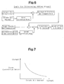
- Fig. 7 is a graph showing the relationship between the intake air amount and the first correction value.
- the first correction value is decreased as the intake air amount increases, that is, as the flow rate of exhaust gas increases.
- the estimated catalyst temperature is calculated by adding a relatively great first correction value to the output gas temperature detected by the output gas temperature sensor 29. Therefore, the correction using the first correction value prevents the output gas temperature detected by the output gas temperature sensor 29 from deviating from the actual output gas temperature.
- Fig. 8 is a graph showing the relationship between the intake air amount and the second correction value.
- the second correction value is increased as the amount of particulate matter accumulated in the PM trapping filter 26 increases, that is, as the amount of heat generated in the PM trapping filter 26 during the temperature increase process increases. Therefore, when the amount of accumulated particulate matter is great, a relatively great second correction value is subtracted from the difference between the estimated catalyst bed temperature and the target catalyst bed temperature to obtain the temperature of the catalyst to be increased by adding fuel.
- the amount of fuel to be added to exhaust gas is adjusted in accordance with the amount of heat generated in the PM trapping filter 26 during the temperature increase process.
- Fig. 9 is a bar graph showing the catalyst bed temperature of the conventional exhaust purifying apparatus, which calculates the amount of fuel to be added to exhaust gas without using the first and second correction values, and the catalyst bed temperature of the exhaust purifying apparatus according to the first embodiment after the temperature increase process.
- fuel is added to exhaust gas by the amount that is necessary and sufficient for increasing the catalyst bed temperature by the difference ⁇ th1 between the detected value THCO of the output gas temperature sensor 29 and the target catalyst bed temperature THCBT.
- the detected value THCO of the output gas temperature sensor 29, that is, the output gas temperature detected by the output gas temperature sensor 29 includes an error ⁇ thcb due to the influence of the flow rate of exhaust gas.
- the detected value THCO of the output gas temperature sensor 29 is less than the actual catalyst bed temperature by the amount corresponding to the error ⁇ thcb. Therefore, when the catalyst bed temperature is increased by the difference ⁇ th1 in the temperature increase process, the catalyst bed temperature after the temperature increase process becomes greater than the target catalyst bed temperature THCB by the error ⁇ thcb. When the particulate matter is partially combusted in the PM trapping filter 26 during the temperature increase process, the catalyst bed temperature after the temperature increase process becomes further greater than the target catalyst bed temperature THCBT by the temperature increase Q due to the combustion.
- the estimated catalyst bed temperature THCB closer to the actual catalyst bed temperature than the detected value THCO is obtained by adding the first correction value, which corresponds to the error ⁇ thcb, to the detected value THCO of the output gas temperature sensor 29. Then, fuel is added to exhaust gas by the amount that is necessary and sufficient for increasing the catalyst bed temperature by a value ⁇ th2 obtained by subtracting the second correction value, which corresponds to the temperature increase Q, from the difference between the estimated catalyst bed temperature THCB and the target catalyst bed temperature THCBT. Therefore, the catalyst bed temperature after the temperature increase process substantially coincides with the target catalyst bed temperature THCBT regardless of the error ⁇ thcb caused by the influence of the flow rate of exhaust gas and the combustion of the particulate matter during the temperature increase process.
- the logic shown in Fig. 6 is executed by the electronic control device 50, which functions as first and second supply amount correcting means and exhaust temperature correcting means.
- the correction of difference between the estimated catalyst bed temperature and the target catalyst bed temperature by the second correction value corresponds to a correction executed by the first supply amount correcting means.
- the correction of the output gas temperature detected by the output gas temperature sensor 29 by the first correction value corresponds to a correction executed by the second supply amount correcting means and the exhaust temperature correcting means.
- the output gas temperature detected by the output gas temperature sensor 29 corresponds to the catalyst bed temperature obtained based on the detected exhaust temperature and the estimated catalyst bed temperature corresponds to the corrected catalyst bed temperature.
- the preferred embodiment provides the following advantages.
- the estimated catalyst bed temperature used instead of the actual catalyst bed temperature when calculating the amount of fuel to be added to exhaust gas during the temperature increase process is obtained by correcting the output gas temperature detected by the output gas temperature sensor 29 based on the intake air amount, which is an indicator of the flow rate of exhaust gas.
- the estimated catalyst bed temperature is a value obtained by eliminating the error due to the flow rate of exhaust gas from the output gas temperature detected by the output gas temperature sensor 29 and is closer to the actual catalyst bed temperature than the output gas temperature detected by the output gas temperature sensor 29. Therefore, the amount of fuel to be added to exhaust gas calculated using the estimated catalyst bed temperature is the amount necessary and sufficient for increasing the catalyst bed temperature to the target catalyst bed temperature.
- Calculating the amount of fuel to be added to exhaust gas during the temperature increase process includes correcting the difference between the estimated catalyst bed temperature and the target catalyst bed temperature based on the accumulated amount of the particulate matter in the PM trapping filter 26. Therefore, even if the particulate matter is combusted in the PM trapping filter 26 during the temperature increase process, an appropriate amount of unburned fuel is supplied to the NOx catalyst and the NOx catalyst is heated in a suitable manner.
- the amount of fuel to be added to exhaust gas is calculated by referring to the output gas temperature detected by the output gas temperature sensor 29, which is located at a section of the exhaust passage 14 downstream of the PM trapping filter 26.
- the amount of fuel to be added to exhaust gas is calculated by referring to the input gas temperature detected by the input gas temperature sensor 28, which is located at a section of the exhaust passage 14 upstream of the PM trapping filter 26, that is, by referring to the detection value of the input gas temperature sensor 28.
- the increase of the catalyst bed temperature due to the combustion of the particulate matter in the PM trapping filter 26 is not reflected in the detection value of the input gas temperature sensor 28. Therefore, the detection value of the input gas temperature sensor 28 is deviated from the actual catalyst bed temperature.
- the amount of fuel to be added to exhaust gas is calculated in accordance with the logic shown in Fig. 10 during the temperature increase process.
- the calculated amount of fuel is added to exhaust gas from the adding valve 46.
- the electronic control device 50 when calculating the amount of fuel to be added to exhaust gas, calculates the estimated catalyst bed temperature by adding first and second correction values to the input gas temperature detected by the input gas temperature sensor 28. Subsequently, the electronic control device 50 obtains the difference between the estimated catalyst bed temperature and the target catalyst bed temperature. From the above described calculation, the temperature of the catalyst that needs to be increased by adding fuel to exhaust gas is obtained. According to the temperature that needs to be increased, the amount of fuel to be added is calculated.
- the second embodiment has the same advantages as the first embodiment.
- the output gas temperature detected by the output gas temperature sensor 29 is corrected using the first correction value. Then, the amount of fuel to be added to exhaust gas is calculated based on the corrected value. However, the amount of fuel to be added may be calculated based on the output gas temperature detected by the output gas temperature sensor 29 first. Then, the calculated value may be corrected using the first correction value. Also, in the first embodiment, the difference between the estimated catalyst bed temperature and the target catalyst temperature is corrected using the second correction value. Then, the amount of fuel to be added to exhaust gas is calculated based on the corrected value. However, the amount of fuel to be added to exhaust gas may be calculated based on the difference between the estimated catalyst bed temperature and the target catalyst bed temperature first. Then, the calculated value may be corrected using the second correction value.
- the input gas temperature detected by the input gas temperature sensor 28 is corrected using the first and second correction values. Then, the amount of fuel to be added to exhaust gas is calculated based on the corrected value. However, the amount of fuel to be added may be calculated based on the input gas temperature detected by the input gas temperature sensor 28 first. Then, the calculated value may be corrected using the first and second correction values.
- the intake air amount detected by the air flow meter 16 is used as an indicator of the flow rate of exhaust gas.
- the flow rate of exhaust gas may be measured and the measurement value may be used instead of the intake air amount.
- the flow rate of exhaust gas may be estimated from the operation condition of the engine such as the engine rotation speed and the engine load and the estimated value may be used instead of the intake air amount.
- the correction using the first correction value may be omitted and only the correction using the second correction value may be performed.
- the unburned fuel is supplied to the catalyst by adding fuel to exhaust gas from the adding valve 46 but fuel may be added by other means.
- the unburned fuel may be supplied to the catalyst by sub-injection of fuel to each combustion chamber 13 from the corresponding injector 40, which is referred to as post injection or after injection.
- the sub-injection is executed during an expansion stroke or an exhaust stroke after the fuel to be combusted in the combustion chamber 13 is injected from the injector 40.
- the amount of fuel to be sub-injected is calculated in accordance with the logic that is the same as the logic shown in Fig. 6 or 10.
- the exhaust purifying apparatus of the above embodiments may be incorporated in an internal combustion engine that has components different from those of the internal combustion engine shown in Fig. 1.
Landscapes
- Engineering & Computer Science (AREA)
- Chemical & Material Sciences (AREA)
- Combustion & Propulsion (AREA)
- Mechanical Engineering (AREA)
- General Engineering & Computer Science (AREA)
- Analytical Chemistry (AREA)
- Chemical Kinetics & Catalysis (AREA)
- Processes For Solid Components From Exhaust (AREA)
- Exhaust Gas After Treatment (AREA)
- Electrical Control Of Air Or Fuel Supplied To Internal-Combustion Engine (AREA)
- Filtering Of Dispersed Particles In Gases (AREA)
Applications Claiming Priority (2)
| Application Number | Priority Date | Filing Date | Title |
|---|---|---|---|
| JP2003321873 | 2003-09-12 | ||
| JP2003321873A JP2005090274A (ja) | 2003-09-12 | 2003-09-12 | 内燃機関の排気浄化装置 |
Publications (2)
| Publication Number | Publication Date |
|---|---|
| EP1515013A2 true EP1515013A2 (fr) | 2005-03-16 |
| EP1515013A3 EP1515013A3 (fr) | 2005-09-21 |
Family
ID=34132064
Family Applications (1)
| Application Number | Title | Priority Date | Filing Date |
|---|---|---|---|
| EP04021624A Withdrawn EP1515013A3 (fr) | 2003-09-12 | 2004-09-10 | Dispositif de purification des gaz d'échappement de moteur à combustion interne |
Country Status (2)
| Country | Link |
|---|---|
| EP (1) | EP1515013A3 (fr) |
| JP (1) | JP2005090274A (fr) |
Cited By (6)
| Publication number | Priority date | Publication date | Assignee | Title |
|---|---|---|---|---|
| WO2006109820A1 (fr) * | 2005-04-08 | 2006-10-19 | Toyota Jidosha Kabushiki Kaisha | Purificateur de gaz d'echappement pour moteur a combustion interne |
| EP1722088A3 (fr) * | 2005-05-13 | 2008-05-28 | HONDA MOTOR CO., Ltd. | Système de traitement des gaz d'échappement d'un moteur à combustion interne |
| EP2077377A1 (fr) | 2008-01-02 | 2009-07-08 | Peugeot Citroën Automobiles S.A. | Circuit de gaz d'échappement d'un moteur à combustion interne |
| RU2390642C2 (ru) * | 2006-12-26 | 2010-05-27 | Тойота Дзидося Кабусики Кайся | Устройство и способ очистки выхлопных газов для двигателей внутреннего сгорания |
| RU2397346C2 (ru) * | 2006-11-27 | 2010-08-20 | Тойота Дзидося Кабусики Кайся | Система очистки выхлопных газов для двигателя внутреннего сгорания |
| US7905086B2 (en) | 2005-09-07 | 2011-03-15 | Isuzu Motors Limited | Method for controlling desulfurization in exhaust gas purification system, and exhaust gas purification system |
Families Citing this family (6)
| Publication number | Priority date | Publication date | Assignee | Title |
|---|---|---|---|---|
| JP3945526B2 (ja) | 2005-09-09 | 2007-07-18 | トヨタ自動車株式会社 | 燃料添加装置 |
| JP4650245B2 (ja) * | 2005-12-02 | 2011-03-16 | トヨタ自動車株式会社 | 内燃機関の排気浄化システム |
| JP2010185423A (ja) * | 2009-02-13 | 2010-08-26 | Toyota Motor Corp | 内燃機関の排気浄化装置 |
| JP5478276B2 (ja) * | 2010-01-26 | 2014-04-23 | 日野自動車株式会社 | パティキュレートフィルタの再生方法 |
| JP5881444B2 (ja) * | 2012-02-01 | 2016-03-09 | 大阪瓦斯株式会社 | エンジンシステムの運転方法およびそのエンジンシステム |
| JP2015169105A (ja) | 2014-03-05 | 2015-09-28 | トヨタ自動車株式会社 | 内燃機関の制御装置 |
Citations (1)
| Publication number | Priority date | Publication date | Assignee | Title |
|---|---|---|---|---|
| WO2003072916A1 (fr) * | 2002-02-26 | 2003-09-04 | Denso Corporation | Dispositif et procede de commande pour moteur a combustion interne |
Family Cites Families (4)
| Publication number | Priority date | Publication date | Assignee | Title |
|---|---|---|---|---|
| ITRM20010391A1 (it) * | 2000-07-07 | 2003-01-07 | Daimler Chrysler Ag | Motore a combustione interna, in particolare per autoveicoli. |
| DE10108720A1 (de) * | 2001-02-23 | 2002-09-05 | Bosch Gmbh Robert | Verfahren und Vorrichtung zur Steuerung einer Brennkraftmaschine |
| JP2002371827A (ja) * | 2001-06-18 | 2002-12-26 | Denso Corp | エンジン用排気浄化装置 |
| JP2003254038A (ja) * | 2002-03-04 | 2003-09-10 | Toyota Motor Corp | 内燃機関の排気浄化装置 |
-
2003
- 2003-09-12 JP JP2003321873A patent/JP2005090274A/ja active Pending
-
2004
- 2004-09-10 EP EP04021624A patent/EP1515013A3/fr not_active Withdrawn
Patent Citations (1)
| Publication number | Priority date | Publication date | Assignee | Title |
|---|---|---|---|---|
| WO2003072916A1 (fr) * | 2002-02-26 | 2003-09-04 | Denso Corporation | Dispositif et procede de commande pour moteur a combustion interne |
Cited By (8)
| Publication number | Priority date | Publication date | Assignee | Title |
|---|---|---|---|---|
| WO2006109820A1 (fr) * | 2005-04-08 | 2006-10-19 | Toyota Jidosha Kabushiki Kaisha | Purificateur de gaz d'echappement pour moteur a combustion interne |
| US7320214B2 (en) | 2005-04-08 | 2008-01-22 | Toyota Jidosha Kabushiki Kaisha | Exhaust gas purifier for internal combustion engine |
| EP1722088A3 (fr) * | 2005-05-13 | 2008-05-28 | HONDA MOTOR CO., Ltd. | Système de traitement des gaz d'échappement d'un moteur à combustion interne |
| US7905086B2 (en) | 2005-09-07 | 2011-03-15 | Isuzu Motors Limited | Method for controlling desulfurization in exhaust gas purification system, and exhaust gas purification system |
| EP1930563A4 (fr) * | 2005-09-07 | 2015-04-08 | Isuzu Motors Ltd | Procédé permettant de contrôler la désulfuration dans un système d'épuration des gaz d'échappement, et système d'épuration des gaz d'échappement |
| RU2397346C2 (ru) * | 2006-11-27 | 2010-08-20 | Тойота Дзидося Кабусики Кайся | Система очистки выхлопных газов для двигателя внутреннего сгорания |
| RU2390642C2 (ru) * | 2006-12-26 | 2010-05-27 | Тойота Дзидося Кабусики Кайся | Устройство и способ очистки выхлопных газов для двигателей внутреннего сгорания |
| EP2077377A1 (fr) | 2008-01-02 | 2009-07-08 | Peugeot Citroën Automobiles S.A. | Circuit de gaz d'échappement d'un moteur à combustion interne |
Also Published As
| Publication number | Publication date |
|---|---|
| JP2005090274A (ja) | 2005-04-07 |
| EP1515013A3 (fr) | 2005-09-21 |
Similar Documents
| Publication | Publication Date | Title |
|---|---|---|
| US8266893B2 (en) | Exhaust gas purification apparatus of internal combustion engine | |
| KR100658818B1 (ko) | 내연기관의 배기 정화 장치 및 배기 정화 방법 | |
| US7607290B2 (en) | Exhaust purifying apparatus for internal combustion engine | |
| US7849677B2 (en) | Regeneration controller for exhaust purification apparatus of internal combustion engine | |
| US7677029B2 (en) | Regeneration controller for exhaust purification apparatus of internal combustion engine | |
| EP1515013A2 (fr) | Dispositif de purification des gaz d'échappement de moteur à combustion interne | |
| EP1515015B1 (fr) | Dispositif de purification des gaz d'échappement pour moteur à combustion interne | |
| US7340884B2 (en) | Exhaust purifying apparatus and exhaust purifying method for internal combustion engine | |
| JP4276472B2 (ja) | 内燃機関の触媒劣化判定装置 | |
| KR100683267B1 (ko) | 내연기관의 배기정화장치 및 배기정화방법 | |
| JP4640318B2 (ja) | 内燃機関の制御装置 | |
| KR100785751B1 (ko) | 내연 기관용 배기 정화 장치 | |
| JP4032774B2 (ja) | 内燃機関の排気浄化装置 | |
| JP4269666B2 (ja) | 内燃機関の排気浄化装置 | |
| JP4190378B2 (ja) | 内燃機関の触媒床温推定装置、及び内燃機関の制御装置 | |
| EP1512849A2 (fr) | Dispositif et procédé d'épuration de gaz d'échappement | |
| JP3858758B2 (ja) | 内燃機関の排気浄化装置 | |
| JP2005299562A (ja) | 内燃機関の排気浄化装置 | |
| JP2008525702A (ja) | 濃度1のディーゼル・エンジンを制御するための方法および装置 | |
| JP2006291827A (ja) | 内燃機関の制御装置 |
Legal Events
| Date | Code | Title | Description |
|---|---|---|---|
| PUAI | Public reference made under article 153(3) epc to a published international application that has entered the european phase |
Free format text: ORIGINAL CODE: 0009012 |
|
| 17P | Request for examination filed |
Effective date: 20040910 |
|
| AK | Designated contracting states |
Kind code of ref document: A2 Designated state(s): AT BE BG CH CY CZ DE DK EE ES FI FR GB GR HU IE IT LI LU MC NL PL PT RO SE SI SK TR |
|
| AX | Request for extension of the european patent |
Extension state: AL HR LT LV MK |
|
| PUAL | Search report despatched |
Free format text: ORIGINAL CODE: 0009013 |
|
| AK | Designated contracting states |
Kind code of ref document: A3 Designated state(s): AT BE BG CH CY CZ DE DK EE ES FI FR GB GR HU IE IT LI LU MC NL PL PT RO SE SI SK TR |
|
| AX | Request for extension of the european patent |
Extension state: AL HR LT LV MK |
|
| RIC1 | Information provided on ipc code assigned before grant |
Ipc: 7F 01N 3/20 B Ipc: 7F 01N 9/00 B Ipc: 7F 01N 3/035 B Ipc: 7F 01N 3/025 B Ipc: 7F 02D 41/02 A |
|
| AKX | Designation fees paid |
Designated state(s): DE ES FR GB IT |
|
| 17Q | First examination report despatched |
Effective date: 20060411 |
|
| STAA | Information on the status of an ep patent application or granted ep patent |
Free format text: STATUS: THE APPLICATION IS DEEMED TO BE WITHDRAWN |
|
| 18D | Application deemed to be withdrawn |
Effective date: 20070822 |