EP1514641A1 - Vorrichtung zur Finishbearbeitung von Wellen, insbesondere Kurbel- und Nockenwellen - Google Patents
Vorrichtung zur Finishbearbeitung von Wellen, insbesondere Kurbel- und Nockenwellen Download PDFInfo
- Publication number
- EP1514641A1 EP1514641A1 EP04020516A EP04020516A EP1514641A1 EP 1514641 A1 EP1514641 A1 EP 1514641A1 EP 04020516 A EP04020516 A EP 04020516A EP 04020516 A EP04020516 A EP 04020516A EP 1514641 A1 EP1514641 A1 EP 1514641A1
- Authority
- EP
- European Patent Office
- Prior art keywords
- belt
- workpiece
- tool carrier
- axis
- grinding
- Prior art date
- Legal status (The legal status is an assumption and is not a legal conclusion. Google has not performed a legal analysis and makes no representation as to the accuracy of the status listed.)
- Withdrawn
Links
- 238000003754 machining Methods 0.000 claims abstract description 31
- 230000002093 peripheral effect Effects 0.000 claims description 6
- 229910000831 Steel Inorganic materials 0.000 abstract 2
- 239000010959 steel Substances 0.000 abstract 2
- 238000010276 construction Methods 0.000 description 2
- 239000013013 elastic material Substances 0.000 description 2
- 239000000463 material Substances 0.000 description 2
- 239000002184 metal Substances 0.000 description 2
- 238000005516 engineering process Methods 0.000 description 1
- 238000004519 manufacturing process Methods 0.000 description 1
Images

Classifications
-
- B—PERFORMING OPERATIONS; TRANSPORTING
- B24—GRINDING; POLISHING
- B24B—MACHINES, DEVICES, OR PROCESSES FOR GRINDING OR POLISHING; DRESSING OR CONDITIONING OF ABRADING SURFACES; FEEDING OF GRINDING, POLISHING, OR LAPPING AGENTS
- B24B21/00—Machines or devices using grinding or polishing belts; Accessories therefor
-
- B—PERFORMING OPERATIONS; TRANSPORTING
- B24—GRINDING; POLISHING
- B24B—MACHINES, DEVICES, OR PROCESSES FOR GRINDING OR POLISHING; DRESSING OR CONDITIONING OF ABRADING SURFACES; FEEDING OF GRINDING, POLISHING, OR LAPPING AGENTS
- B24B19/00—Single-purpose machines or devices for particular grinding operations not covered by any other main group
- B24B19/08—Single-purpose machines or devices for particular grinding operations not covered by any other main group for grinding non-circular cross-sections, e.g. shafts of elliptical or polygonal cross-section
-
- B—PERFORMING OPERATIONS; TRANSPORTING
- B24—GRINDING; POLISHING
- B24B—MACHINES, DEVICES, OR PROCESSES FOR GRINDING OR POLISHING; DRESSING OR CONDITIONING OF ABRADING SURFACES; FEEDING OF GRINDING, POLISHING, OR LAPPING AGENTS
- B24B19/00—Single-purpose machines or devices for particular grinding operations not covered by any other main group
- B24B19/08—Single-purpose machines or devices for particular grinding operations not covered by any other main group for grinding non-circular cross-sections, e.g. shafts of elliptical or polygonal cross-section
- B24B19/12—Single-purpose machines or devices for particular grinding operations not covered by any other main group for grinding non-circular cross-sections, e.g. shafts of elliptical or polygonal cross-section for grinding cams or camshafts
-
- B—PERFORMING OPERATIONS; TRANSPORTING
- B24—GRINDING; POLISHING
- B24B—MACHINES, DEVICES, OR PROCESSES FOR GRINDING OR POLISHING; DRESSING OR CONDITIONING OF ABRADING SURFACES; FEEDING OF GRINDING, POLISHING, OR LAPPING AGENTS
- B24B5/00—Machines or devices designed for grinding surfaces of revolution on work, including those which also grind adjacent plane surfaces; Accessories therefor
- B24B5/36—Single-purpose machines or devices
- B24B5/42—Single-purpose machines or devices for grinding crankshafts or crankpins
Definitions
- the invention relates to a device for finish machining of shafts, in particular of crankshafts and camshafts with Tool carrier, endless grinding belt for machining a workpiece rotating about its axis of rotation, a grinding belt drive arranged on the tool carrier, which continuously drives the grinding belt during workpiece machining and a tensioning device for the sanding belt, wherein the tool carrier has a machining head with two mutually spaced band deflections which delimit a working area of the machining head and wherein the sanding belt is guided over the tape deflections and runs in the working area over the peripheral surface of the workpiece to be machined and wherein the machining head bifurcates the peripheral surface of the workpiece to be machined encompasses that the grinding belt, which is exposed in the working area, partially wraps around the workpiece and rests flat against the workpiece in a region predetermined by the wrap angle.
- a device with the features described above is known from Publication US 6,220,946 B1 known.
- the Processing head pivotally mounted on the tool carrier, which is guided linearly movable on an adjusting spindle.
- Around circulating Circumferential surfaces of crankshafts and camshafts must be able to work the tool carrier perform linear positioning movements, which are on the Rotation speed of the workpiece and the pivoting movements of the Machining head must be coordinated.
- the apparatus and control technology Effort is great.
- the invention is based on the object, a device with the above specify features that are simple and inexpensive Finish machining of shafts, especially crankshafts and camshafts, allows and manufactured with the workpiece surfaces with high surface quality are.
- the object is achieved in that the tool carrier is pivotally mounted about an axis of rotation, which is parallel to the axis of rotation of the workpiece is aligned and in one between the machining head and the grinding belt drive lying tool carrier area is arranged. Due to the looping of the workpiece through the abrasive belt is a Large contact surface with uniform surface pressure between abrasive belt and workpiece surface to be machined.
- the designed as a swivel arm Tool holder can by an oscillating pivoting movement follow circumferential workpiece surfaces of cam and crankshaft, wherein the contact area between abrasive belt and workpiece within the Move workspace during the orbital movement accordingly.
- the Device according to the invention Due to the simple construction and mode of operation allows the Device according to the invention an inexpensive finish machining of wave-shaped workpieces, for example, crankshafts and camshafts.
- the device is flexible and therefore especially for the Production of individual parts or small series suitable.
- the Distance of the grinding belt drive from the axis of rotation of the tool carrier so established that a large mass balance around the axis of rotation given vibrating masses.
- the tool carrier can z.
- the tool carrier can be mounted on a feed device, the Performing movements against the workpiece performs.
- the delivery stroke is the wrap angle of the abrasive belt changeable, wherein the Pressure force of the grinding belt practically independent of the wrap angle is.
- the delivery device is further along the axis of rotation of the Workpiece movable.
- the tensioning device is preferably on Tool carrier arranged.
- Band storage be arranged in which the sanding belt a belt loop forms, wherein the length of the belt loop by means of an adjusting device is adjustable. This allows a variable adjustment of the wrap angle between abrasive belt and workpiece over a large area. to Implementation of different processing steps can the Loop angle also changed during workpiece machining become.
- the tape store is preferably arranged on the tool carrier.
- the work area limiting band deflections can relatively be arranged adjustable to each other.
- the Processing head have pivotable fork arms, where the Band deflections are arranged. This allows the setting of a large one Wrap angle between abrasive belt and workpiece. Especially in this case wrap angles of more than 180 ° can be realized.
- the sanding belt can be assigned a support band, which is in the work area is stretched parallel to the sanding belt and the back of the sanding belt supported.
- the support band can be made of a tensile material, such as metal, or but also consist of a rubber-elastic material.
- the support band can be firmly connected to the tool carrier.
- the support band runs also around.
- the support band on the tool carrier as Endless band over band deflections and a separate tensioning device be guided by the sanding belt drive or a separate drive are driven.
- the abrasive belt and the support belt lead rectified revolutions with the same belt speed. As a result, an optimal strain relief of the sanding belt is possible.
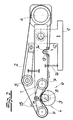
- the device has a Tool carrier 1, an endless sanding belt 2 for processing a his Rotation axis A rotating workpiece 3, one on the tool carrier. 1 arranged abrasive belt drive 4, which the abrasive belt 2 during a Workpiece machining drives continuously, and one on the tool carrier. 1 arranged clamping device 5 for the sanding belt 2.
- the tool carrier 1 has a machining head 6 with two spaced-apart Band deflections 7, a working area L of the machining head. 6 limit and are formed in the embodiment as deflection rollers.
- the Sanding belt 2 is guided over the deflection rollers 7 and runs in the working area L.
- Der Processing head 6 surrounds the peripheral surface to be machined Workpiece 3 bifurcated so that the freely stretched in the working area L.
- Sanding belt 2 the workpiece 3 partially wraps around and in a through the Wrap angle ⁇ given area flat against the workpiece 3.
- the tool carrier 1 is pivotally mounted about a rotation axis B, the is aligned parallel to the axis of rotation A of the workpiece 3 and in one between the machining head 6 and the sanding belt drive 4 lying Tool carrier area is arranged.
- the device according to the invention ensures a large contact surface with uniform surface pressure between the grinding belt 2 and the workpiece surface to be machined. As a result, very high surface finishes can be achieved.
- the as a swivel arm Trained tool carrier 1 follows by an oscillating pivoting movement the orbital movement of the embodiment as a crankshaft trained workpiece 3.
- a finish machining is such Workpieces with a comparatively simple construction possible.
- the device according to the invention is suitable as an additional device for lathes, on which the workpiece for finish machining between spindle and Tailstock is tensioned. It can be located on the lathe Tool slides are mounted.
- the grinding belt 2 Due to the arrangement of the tool carrier rotation axis B between the Processing head 6 and the sanding belt drive 4 is the grinding belt 2 with an adjustable force on the workpiece surface to be machined. in the Embodiment is the distance of the sanding belt drive 4 from the axis of rotation B of the tool carrier 1 set so that a broader Mass balance of the oscillating about the rotation axis B masses is given.
- To set a defined pressure between sanding belt 2 and Workpiece surface is one along the tool carrier 1 slidably arranged mass 8 arranged before the start of processing on a certain position can be locked.
- the tool carrier 1 is at a Positioning device 9 stored, the feed movements against the workpiece. 3 performs.
- the delivery device may also be a tool carriage a conventional universal lathe act.
- the tool carrier with a substantially horizontal extension shown can also be vertical or with a be arranged in any orientation.
- the abrasive belt 2 is associated with a support band 10, which in the Work area L is stretched parallel to the sanding belt 2 and the back of the Abrasive belt 2 is supported.
- the support band 10 is made in the embodiment Metal. Alternatively, however, elastic materials, for example Rubber, used as a support material.
- the support band 10 is in Embodiment on the tool carrier 1 as an endless belt on the Deflection rollers 7 and a separate clamping device 11 is guided and will also driven by the sanding belt drive 4.
- a separate support belt drive and a separate guide within the Work area be provided.
- the sanding belt 2 and the support belt 10 lead rectified revolutions with the same belt speed out. This ensures that in the contact area between abrasive belt 2 and support belt 10 virtually no relative movement between the two Bands 2, 10 is present. This leads to an optimal discharge of the Sanding belt 2.
- Fig. 2 is in the circulation path of the abrasive belt 2, a tape storage 12th arranged in which the sanding belt 2 forms a belt loop 13.
- the length the belt loop 13 is by means of a sliding guide role trained adjusting device 14 adjustable.
- the wrap angle ⁇ between the grinding belt 2 and the workpiece 3 via be varied variably over a large area.
- the tape storage 12 is arranged on the tool carrier 1.
- the work area limiting Pulleys 7 are also arranged relative to each other adjustable.
- the in Fig. 2 processing head 6 has pivotable fork arms 15 on where the pulleys 7 are arranged.
- an adjustable spring 16 is provided on the tool carrier 1, which is connected to the delivery device 9.
- the workpiece 3 rotates in each case counter to the direction of rotation of the grinding belt 2, so that a very high relative speed between sanding belt 2 and machined Workpiece surface is present, which for the achievement of very good Finishing results is important.
Landscapes
- Engineering & Computer Science (AREA)
- Mechanical Engineering (AREA)
- Finish Polishing, Edge Sharpening, And Grinding By Specific Grinding Devices (AREA)
- Grinding And Polishing Of Tertiary Curved Surfaces And Surfaces With Complex Shapes (AREA)
Abstract
Description
Werkzeugträger,
endlosem Schleifband zur Bearbeitung eines um seine Rotationsachse rotierenden Werkstückes,
einem am Werkzeugträger angeordneten Schleifbandantrieb, welcher das Schleifband während einer Werkstückbearbeitung kontinuierlich antreibt und
einer Spannvorrichtung für das Schleifband,
wobei der Werkzeugträger einen Bearbeitungskopf mit zwei zueinander beabstandeten Bandumlenkungen aufweist, die einen Arbeitsbereich des Bearbeitungskopfes begrenzen und wobei das Schleifband über die Bandumlenkungen geführt ist und im Arbeitsbereich über die zu bearbeitende Umfangfläche des Werkstückes läuft und wobei der Bearbeitungskopf die zu bearbeitende Umfangfläche des Werkstückes gabelförmig so umgreift, dass das im Arbeitsbereich freigespannte Schleifband das Werkstück teilweise umschlingt und in einem durch den Umschlingungswinkel vorgegebenen Bereich flächig am Werkstück anliegt.
- Fig. 1
- eine Seitenansicht einer erfindungsgemäßen Vorrichtung zur Finishbearbeitung von Wellen und
- Fig. 2
- eine weitere Ausgestaltung der erfindungsgemäßen Vorrichtung ebenfalls in einer Seitenansicht.
Claims (10)
- Vorrichtung zur Finishbearbeitung von Wellen, insbes. von Kurbel- und Nockenwellen mit
Werkzeugträger (1),
endlosem Schleifband (2) zur Bearbeitung eines um seine Rotationsachse (A) rotierenden Werkstückes (3),
einem am Werkzeugträger (1) angeordneten Schleifbandantrieb (4), welcher das Schleifband (2) während einer Werkstückbearbeitung kontinuierlich antreibt und
einer Spannvorrichtung (5) für das Schleifband (2),
wobei der Werkzeugträger (1) einen Bearbeitungskopf (6) mit zwei zueinander beabstandeten Bandumlenkungen (7) aufweist, die einen Arbeitsbereich (L) des Bearbeitungskopfes begrenzen (6), wobei das Schleifband (2) über die Bandumlenkungen (7) geführt ist und im Arbeitsbereich (L) über die zu bearbeitende Umfangsfläche des Werkstückes (3) läuft und wobei der Bearbeitungskopf (6) die zu bearbeitende Umfangsfläche des Werkstückes (3) gabelförmig so umgreift, dass das im Arbeitsbereich (L) frei gespannte Schleifband (2) das Werkstück (3) teilweise umschlingt und in einem durch den Umschlingungswinkel (α) vorgegebenen Bereich flächig am Werkstück (3) anliegt, dadurch gekennzeichnet, dass der Werkzeugträger (1) schwenkbar um eine Drehachse (B) gelagert ist, die parallel zur Rotationsachse (A) des Werkstückes (3) ausgerichtet ist und in einem zwischen dem Bearbeitungskopf (6) und dem Schleifbandantrieb (4) liegenden Werkzeugträgerbereich angeordnet ist. - Vorrichtung nach Anspruch 1, dadurch gekennzeichnet, dass der Abstand des Schleifbandantriebes (4) von der Drehachse (B) des Werkzeugträgers (1) so festgelegt ist, dass ein weitgehender Massenausgleich der um die Drehachse (B) schwingenden Massen gegeben ist.
- Vorrichtung nach Anspruch 1 oder 2, dadurch gekennzeichnet, dass der Werkzeugträger (1) an einer Zustelleinrichtung (9) gelagert ist, die Zustellbewegungen gegen das Werkstück ausführt.
- Vorrichtung nach einem der Ansprüche 1 bis 3, dadurch gekennzeichnet, dass die Spannvorrichtung (5) am Werkzeugträger (1) angeordnet ist.
- Vorrichtung nach einem der Ansprüche 1 bis 4, dadurch gekennzeichnet, dass im Umlaufweg des Schleifbandes (2) ein Bandspeicher (12) angeordnet ist, in dem das Schleifband (2) eine Bandschlaufe (13) bildet, und dass die Länge der Bandschlaufe (13) mittels einer Stelleinrichtung (14) einstellbar ist.
- Vorrichtung nach Anspruch 5, dadurch gekennzeichnet, dass der Bandspeicher (12) am Werkzeugträger (1) angeordnet ist.
- Vorrichtung nach einem der Ansprüche 1 bis 6, dadurch gekennzeichnet, dass die den Arbeitsbereich (L) begrenzenden Bandumlenkungen (7) relativ zueinander verstellbar angeordnet sind.
- Vorrichtung nach Anspruch 7, dadurch gekennzeichnet, dass der Bearbeitungskopf (6) verschwenkbare Gabelarme (15) aufweist, an denen die Bandumlenkungen (7) angeordnet sind.
- Vorrichtung nach einem der Ansprüche 1 bis 8, dadurch gekennzeichnet, dass dem Schleifband (2) ein Stützband (10) zugeordnet ist, das im Arbeitsbereich (L) parallel zum Schleifband (2) gespannt ist und die Rückseite des Schleifbandes (2) abstützt.
- Vorrichtung nach Anspruch 9, dadurch gekennzeichnet, dass das Stützband (10) am Werkzeugträger (1) als Endlosband über Bandumlenkungen (7) und eine separate Spanneinrichtung (11) geführt ist und von dem Schleifbandantrieb (4) oder einem separaten Antrieb angetrieben wird.
Applications Claiming Priority (2)
| Application Number | Priority Date | Filing Date | Title |
|---|---|---|---|
| DE10342135 | 2003-09-12 | ||
| DE2003142135 DE10342135A1 (de) | 2003-09-12 | 2003-09-12 | Vorrichtung zur Finishbearbeitung von Wellen, insbesondere Kurbel- und Nockenwellen |
Publications (1)
| Publication Number | Publication Date |
|---|---|
| EP1514641A1 true EP1514641A1 (de) | 2005-03-16 |
Family
ID=34129775
Family Applications (1)
| Application Number | Title | Priority Date | Filing Date |
|---|---|---|---|
| EP04020516A Withdrawn EP1514641A1 (de) | 2003-09-12 | 2004-08-28 | Vorrichtung zur Finishbearbeitung von Wellen, insbesondere Kurbel- und Nockenwellen |
Country Status (2)
| Country | Link |
|---|---|
| EP (1) | EP1514641A1 (de) |
| DE (1) | DE10342135A1 (de) |
Cited By (4)
| Publication number | Priority date | Publication date | Assignee | Title |
|---|---|---|---|---|
| CN107088813A (zh) * | 2017-07-13 | 2017-08-25 | 哈尔滨工业大学深圳研究生院 | 一种机器人用砂带磨削单元 |
| CN110539234A (zh) * | 2019-08-23 | 2019-12-06 | 沈阳工业大学 | 一种细长轴类抛光加工装置 |
| CN110561242A (zh) * | 2019-10-19 | 2019-12-13 | 贵州师范大学 | 一种基于光纤线缆表皮的再次加工磨光设备 |
| CN115229625A (zh) * | 2022-09-21 | 2022-10-25 | 山东辰榜数控装备有限公司 | 一种短轴加工用可调节式数控机床 |
Families Citing this family (3)
| Publication number | Priority date | Publication date | Assignee | Title |
|---|---|---|---|---|
| DE102005026296C5 (de) * | 2005-06-08 | 2012-02-02 | Supfina Grieshaber Gmbh & Co. Kg | Vorrichtung zum Superfinishen mit einem externen Antrieb |
| DE102006052829A1 (de) * | 2006-11-09 | 2008-05-15 | Thielenhaus Technologies Gmbh | Verfahren zur Bandfinishbearbeitung von Werkstückenumfangsflächen |
| DE102019125855A1 (de) * | 2019-09-25 | 2021-03-25 | Thielenhaus Technologies Gmbh | Werkzeughalter zum Andrücken eines Finishwerkzeuges an eine Umfangsfläche eines Nockens und Maschine zur Finishbearbeitung |
Citations (2)
| Publication number | Priority date | Publication date | Assignee | Title |
|---|---|---|---|---|
| US6220946B1 (en) * | 1998-02-13 | 2001-04-24 | Philip D. Arnold | Active polishing of rotatable article surfaces |
| FR2825652A1 (fr) * | 2001-06-06 | 2002-12-13 | Procedes Et Machines Speciales | Machine d'usinage par abrasif de portees d'une piece, notamment de superfinition de manetons de vilebrequins |
Family Cites Families (3)
| Publication number | Priority date | Publication date | Assignee | Title |
|---|---|---|---|---|
| FR1329559A (fr) * | 1956-12-28 | 1963-06-14 | Procédé et dispositifs pour la finition de pièces métalliques | |
| AT4931U1 (de) * | 2001-01-25 | 2002-01-25 | Hammerschmid Johann | Bandschleifmaschine |
| DE10200489A1 (de) * | 2002-01-07 | 2003-07-24 | Preuss Rolf | Kombinationsbandschleifgerät |
-
2003
- 2003-09-12 DE DE2003142135 patent/DE10342135A1/de not_active Withdrawn
-
2004
- 2004-08-28 EP EP04020516A patent/EP1514641A1/de not_active Withdrawn
Patent Citations (2)
| Publication number | Priority date | Publication date | Assignee | Title |
|---|---|---|---|---|
| US6220946B1 (en) * | 1998-02-13 | 2001-04-24 | Philip D. Arnold | Active polishing of rotatable article surfaces |
| FR2825652A1 (fr) * | 2001-06-06 | 2002-12-13 | Procedes Et Machines Speciales | Machine d'usinage par abrasif de portees d'une piece, notamment de superfinition de manetons de vilebrequins |
Cited By (6)
| Publication number | Priority date | Publication date | Assignee | Title |
|---|---|---|---|---|
| CN107088813A (zh) * | 2017-07-13 | 2017-08-25 | 哈尔滨工业大学深圳研究生院 | 一种机器人用砂带磨削单元 |
| CN107088813B (zh) * | 2017-07-13 | 2023-07-07 | 哈尔滨工业大学深圳研究生院 | 一种机器人用砂带磨削单元 |
| CN110539234A (zh) * | 2019-08-23 | 2019-12-06 | 沈阳工业大学 | 一种细长轴类抛光加工装置 |
| CN110561242A (zh) * | 2019-10-19 | 2019-12-13 | 贵州师范大学 | 一种基于光纤线缆表皮的再次加工磨光设备 |
| CN115229625A (zh) * | 2022-09-21 | 2022-10-25 | 山东辰榜数控装备有限公司 | 一种短轴加工用可调节式数控机床 |
| CN115229625B (zh) * | 2022-09-21 | 2022-12-06 | 山东辰榜数控装备有限公司 | 一种短轴加工用可调节式数控机床 |
Also Published As
| Publication number | Publication date |
|---|---|
| DE10342135A1 (de) | 2005-04-07 |
Similar Documents
| Publication | Publication Date | Title |
|---|---|---|
| DE4226708C2 (de) | Bandschleifmaschine | |
| EP1514640B1 (de) | Verfahren und Vorrichtung zur Finishbearbeitung von Wellen, insbesondere von Kurbel- und Nockenwellen | |
| DE60000670T2 (de) | Bandschleifmaschine mit um eine Umlaufbahn bewegtem Schleifband | |
| EP2769806B1 (de) | Vorrichtung und System zur Finishbearbeitung eines Werkstücks in Form einer Kurbelwelle oder einer Nockenwelle | |
| DE19825698A1 (de) | Bandschleifmaschine | |
| EP1990133B1 (de) | Schleifaggregat als Werkzeug für eine Bearbeitungsvorrichtung | |
| EP3135433A2 (de) | Umfangsflächenbearbeitungseinheit, werkzeugmaschine und verfahren zum betrieb | |
| DE19723306C2 (de) | Verfahren und Vorrichtung zum Schleifen oder Polieren von Stirnflächen plattenförmiger Körper | |
| EP2636482B1 (de) | Werkstückbearbeitungssystem und Verfahren zur Feinstbearbeitung eines Werkstücks | |
| EP0276439B1 (de) | Verfahren zum Innenschleifen von langen Bohrungen mit extrem geringem Durchmesser in Werkstücken und Vorrichtung zur Durchführung des Verfahrens | |
| DE4227315C2 (de) | Maschine zum Schleifen, Kurzhubhonen und Polieren der Außenoberfläche von Werkstücken | |
| DE10342135A1 (de) | Vorrichtung zur Finishbearbeitung von Wellen, insbesondere Kurbel- und Nockenwellen | |
| EP2210706B1 (de) | Einrichtung zur Bandführung einer Bandschleifmaschine | |
| DE102014211937C5 (de) | Verfahren und Vorrichtung zur Finish-Bearbeitung von Umfangsflächen rotationssymmetrischer Werkstückabschnitte | |
| DE3312133A1 (de) | Schaumstoff-formschneidemaschine, insbesondere fuer numerische werkzeugsteuerung | |
| DE10342139B4 (de) | Verfahren zur Finishbearbeitung von Umfangsflächen an wellenförmigen Werkstücken | |
| EP2596907A1 (de) | Vorrichtung zur Finishbearbeitung einer gekrümmten Werkstückoberfläche | |
| DE202009004809U1 (de) | Rohrausschleifmaschine mit einstellbarer Seitenführung des Schleifbandes | |
| DE19821982A1 (de) | Profil-Bandschleifmaschine | |
| DE102009025784A1 (de) | Rohrausschleifmaschine mit einstellbarer Seitenführung des Schleifbandes | |
| DE10342137B4 (de) | Vorrichtung und Verfahren zur Finishbearbeitung von Wellen, insbesondere von Kurbel- und Nockenwellen | |
| DE3918847C2 (de) | ||
| EP2617523A1 (de) | Finishvorrichtung zur finishenden Bearbeitung eines Werkstücks | |
| EP2095906A1 (de) | Vorrichtung zur mechanischen Finishbearbeitung von Laufflächen an Wälzlagerringen | |
| DE102018101339B4 (de) | Bandfinishvorrichtung |
Legal Events
| Date | Code | Title | Description |
|---|---|---|---|
| PUAI | Public reference made under article 153(3) epc to a published international application that has entered the european phase |
Free format text: ORIGINAL CODE: 0009012 |
|
| AK | Designated contracting states |
Kind code of ref document: A1 Designated state(s): AT BE BG CH CY CZ DE DK EE ES FI FR GB GR HU IE IT LI LU MC NL PL PT RO SE SI SK TR |
|
| AX | Request for extension of the european patent |
Extension state: AL HR LT LV MK |
|
| 17P | Request for examination filed |
Effective date: 20050204 |
|
| AKX | Designation fees paid |
Designated state(s): DE FR GB IT |
|
| GRAP | Despatch of communication of intention to grant a patent |
Free format text: ORIGINAL CODE: EPIDOSNIGR1 |
|
| STAA | Information on the status of an ep patent application or granted ep patent |
Free format text: STATUS: THE APPLICATION IS DEEMED TO BE WITHDRAWN |
|
| 18D | Application deemed to be withdrawn |
Effective date: 20060628 |