EP1513421B1 - Walzenpaar zum spannen von strängen aus filtermaterial - Google Patents
Walzenpaar zum spannen von strängen aus filtermaterial Download PDFInfo
- Publication number
- EP1513421B1 EP1513421B1 EP03732427A EP03732427A EP1513421B1 EP 1513421 B1 EP1513421 B1 EP 1513421B1 EP 03732427 A EP03732427 A EP 03732427A EP 03732427 A EP03732427 A EP 03732427A EP 1513421 B1 EP1513421 B1 EP 1513421B1
- Authority
- EP
- European Patent Office
- Prior art keywords
- roller
- drive
- pair according
- roller pair
- shaft
- Prior art date
- Legal status (The legal status is an assumption and is not a legal conclusion. Google has not performed a legal analysis and makes no representation as to the accuracy of the status listed.)
- Expired - Lifetime
Links
Images

Classifications
-
- A—HUMAN NECESSITIES
- A24—TOBACCO; CIGARS; CIGARETTES; SIMULATED SMOKING DEVICES; SMOKERS' REQUISITES
- A24D—CIGARS; CIGARETTES; TOBACCO SMOKE FILTERS; MOUTHPIECES OF CIGARS OR CIGARETTES; MANUFACTURE OF TOBACCO SMOKE FILTERS OR MOUTHPIECES
- A24D3/00—Tobacco smoke filters, e.g. filter tips or filtering inserts; Filters specially adapted for simulated smoking devices; Mouthpieces of cigars or cigarettes
- A24D3/02—Manufacture of tobacco smoke filters
- A24D3/0204—Preliminary operations before the filter rod forming process, e.g. crimping, blooming
Definitions
- the invention relates to a roller pair for tensioning strands of filter material in the manufacture of cigarette filters according to the preamble of patent claim 1.
- the filter of filter cigarettes are usually made of a so-called filter tow of cellulose acetate. It is stripped from a bale of cellulose acetate and formed into a web or strand prior to being fed to the machine in which the filter plugs are made. The "cable" removed from the bale is heavily curled and is therefore subjected to tensile stress for expansion.
- two spaced-apart pairs of rollers are provided, of which the one which is driven in the transport direction from the lying at a greater speed than the rear, so as to generate a voltage.
- roller pairs used for this purpose are mounted on one end of the frame of the machine, one roller being made of metal and the other being a surface layer of elastic material, e.g. Having rubber or the like.
- Such arrangements are i.a. in DE 1 532 142 or DE 2 008 033.
- the overhead metal roller is driven, while the lower roller is mounted to run.
- the lower roller is pivotally mounted about a horizontal axis near its bearing.
- a linear pneumatic drive is provided to operate the pivoting.
- the invention has for its object to change roller pair of the specified type to the effect that the wear is reduced.
- the second roller of a drive via a second drive shaft and a propeller shaft is driven.
- the second drive shaft is coupled via a gear transmission with the first drive shaft. Therefore, an additional drive is not required.
- the second roller is also mounted so that the size of the gap between the rollers in adaptation to the thickness of the material over its length is variable.
- the contact pressure must be only so large that the acetate fibers between the spaced pairs of rollers can be held in order to stretch them in a certain ratio. In this way, the wear of the lining of the second roller is significantly reduced.
- the second roller is not only pivoted away from the first roller, but can also make a pivoting during operation within limits or undergo an adjustment parallel to itself, if this is expedient due to the thickness of the material.
- the resistance that must be overcome in such a movement of the second roller is that of the pivot drive, which therefore expediently acts on the second roller via a spring medium.
- the actuator in turn includes a pneumatic cylinder that automatically allows a limited pivoting of the roller.
- another actuator can act on the pivoting of the second roller via a spring medium.
- the second roller is coupled via a universal joint shaft to the second drive shaft.
- the second drive shaft may, as already mentioned, be the output shaft of a toothed wheel drive, whose input shaft represents the motor shaft.
- the second roller is hollow. Inside, a drive flange is fixed, which cooperates with a roller bearing, whose inner ring is mounted pivotably about a horizontal axis on a sleeve-shaped bearing component.
- the propeller shaft is passed through the sleeve-shaped component.
- the sleeve-shaped component is in turn pivotally mounted about a horizontal axis on the frame.
- the bearing component is pivotally mounted and can transmit this movement to the roller.
- the roller is in turn pivotally mounted on the bearing component, so that it is also adjustable parallel to itself in order to adapt to the thickness of the filter tow.
- the arrangement of the roller pair including the gear parts may be designed so that it can be attached to a conventional roller drive.
- the frame has a vertical support plate on which Flanged on one side of the drive motor, as it is known.
- a gear box for the gear transmission is mounted, which in turn allows the storage of the second roller.
- the rollers can be mounted together with the gear box and the gear housed therein as a unit to the conventional support plate.
- a second drive can be provided for the second roller, which preferably runs with a torque which compensates for the bearing friction. The speed of the second drive is adjusted so that the peripheral speed of both rollers is equal, so that friction in the nip does not occur.
- the z. B. may be an air motor or a hydraulic motor, the contact pressure between the rollers can be reduced because the frictional forces of the bearings no longer need to be overcome.
- an overrunning clutch is provided according to an embodiment of the invention for the fast startup phase of the machine up to production speed. This allows the second roller to follow the first one. Under certain circumstances, it may be necessary to briefly increase the contact pressure during this startup time.
- the system described last provides a relatively resilient drive which can easily compensate for variations in speed and ensures that the upper and lower rollers move in lockstep.
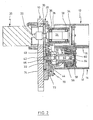
- a support plate 10 can be seen, which is part of a machine frame of a machine, which serves for the preparation of a so-called filter tow.
- a so-called filter tow To this plant belong two pairs of rolls, one of which is shown in FIGS. 1 to 3.
- the second pair may have the same structure or be conventional.
- FIGS. 1 to 3 an upper roller 12 and a lower roller 14 can be seen.
- the upper hollow roll is made of metal, while the lower roll 14 has a hollow metal shell 16 and a rubber coating 18.
- an electric motor 20 is flanged on the left side of the vertical support plate 10. Its drive shaft 22 is coupled via a coupling with a further shaft 24 which extends into a sleeve-shaped bearing body 26.
- the bearing body 26 is flanged to a transmission housing 28 which receives two spur gears 30, 32.
- the spur gear 30 is seated on the shaft 24 and meshes with the second spur gear 32.
- the gear ratio is 1: 1.
- the transmission housing 28 is fixedly connected to the support plate 10.
- the shaft 24 is rotatably connected to a flange 34, which in turn is clamped within the roller 32. A rotation of the shaft 24 thus leads to a corresponding rotation of the roller 12.
- the roller 12 is held centrally only at one point. The load is absorbed by the shaft 24, which is mounted by means of rolling bearings 36, 38 within the bearing body 26.
- a bearing flange 40 is connected by screw mounting, which rotatably supports a pin 46 by means of two roller bearings 42, 44, which is rotatably connected to the lower spur gear 32.
- a sleeve-shaped bearing component 50 is pivotally supported by the bearing flange 32. In FIGS. 1 to 3, this bearing takes place about a horizontal axis.
- the sleeve-shaped bearing member 50 by means of two diametrically opposed bearing journals 52, 54, the inner rings of two bearings 56, 58.
- the outer ring of the bearings 56, 58 is rotatably connected to the inside of the roller 14 ,
- a flange 60 is connected, with which the right end of a propeller shaft 62 is coupled torsionally rigid.
- the propeller shaft has a first universal joint 64 and a second universal joint 66, by means of which the latter an articulation takes place on the journal 46.
- the propeller shaft 62 extends through the interior of the sleeve-shaped bearing member 50. The interior of which is protected by a protective membrane 68 against ingress of dirt.
- an angular component 70 is screwed to the underside, which rests in Fig. 1 on a stop 72 which is connected to the transmission housing 28.
- a pneumatic Verstellzylinderan extract 74 is articulated on the lower leg of the component 70. With the help of Verstellzylinderan effet 74 can thus be pivoted upwardly the lower roller, as shown in Fig. 2.
- the pressure with which the two rollers 12, 14 are pressed against one another is predetermined by the pressure in the cylinder arrangement 74.
Landscapes
- Preliminary Treatment Of Fibers (AREA)
- Filtering Materials (AREA)
- Press Drives And Press Lines (AREA)
- Rollers For Roller Conveyors For Transfer (AREA)
- Details Of Cutting Devices (AREA)
- Metal Rolling (AREA)
- Manufacturing Of Cigar And Cigarette Tobacco (AREA)
- Shaping By String And By Release Of Stress In Plastics And The Like (AREA)
- Paper (AREA)
Description
- Die Erfindung bezieht sich auf ein Walzenpaar zum Spannen von Strängen aus Filtermaterial bei der Herstellung von Zigarettenfiltem nach dem Oberbegriff des Patentanspruchs 1.
- Die Filter von Filterzigaretten werden üblicherweise aus einem sogenannten Filtertow aus Zelluloseacetat hergestellt. Es wird von einem Ballen aus Zelluloseacetat abgezogen und zu einer Bahn oder einem Strang geformt, bevor es der Maschine zugeleitet wird, in welcher die Filterpfropfen hergestellt werden. Das vom Ballen abgezogene "Kabel" ist stark gekräuselt und wird daher zur Ausbreitung unter Zugspannung gesetzt. Zu diesem Zwecke sind zwei beabstandete Walzenpaare vorgesehen, von denen das in Transportrichtung vom liegende mit größerer Geschwindigkeit angetrieben wird als das hintere, um auf diese Weise eine Spannung zu erzeugen.
- Die hierzu verwendeten Walzenpaare sind am Rahmen der Maschine einendig gelagert, wobei eine Walze aus Metall besteht und die andere eine Oberflächenschicht aus elastischem Material, z.B. Gummi oder dergleichen aufweist. Derartige Vorkehrungen sind u.a. in DE 1 532 142 oder DE 2 008 033 beschrieben.
- Bei den bekannten Walzenpaaren ist die oben liegende aus Metall bestehende Walze angetrieben, während die untere Walze mitlaufend gelagert ist. Zum Einfädeln des Filtertows ist die untere Walze um eine horizontale Achse nahe ihrer Lagerung schwenkbar gelagert. Zur Betätigung der Verschwenkung ist ein linearer pneumatischer Antrieb vorgesehen.
- Damit eine gewisse Reckung des Tows schlupffrei erfolgen kann, muß die untere Walze mit relativ hoher Preßkraft angedrückt werden. Hierdurch erfährt die Gummibeschichtung der unteren Walze jedoch einen nicht unbeträchtlichen Verschleiß.
- Der Erfindung liegt die Aufgabe zugrunde, Walzenpaar der angegebenen Art dahingehend abzuändern, daß der Verschleiß verringert wird.
- Diese Aufgabe wird durch die Merkmale des Patentanspruchs 1 gelöst.
- Bei der Erfindung ist auch die zweite Walze von einem Antrieb über eine zweite Antriebswelle und eine Gelenkwelle antreibbar. Nach einer Ausgestaltung der Erfindung ist die zweite Antriebswelle über ein Zahnradgetriebe mit der ersten Antriebswelle gekoppelt. Daher ist ein zusätzlicher Antrieb nicht erforderlich.
- Erfindungsgemäß ist ferner die zweite Walze so gelagert, daß die Größe des Spaltes zwischen den Walzen in Anpassung an die Dicke des Materials über seine Länge veränderbar ist.
- Bei der Erfindung muß der Anpreßdruck nur noch so groß sein, daß die Acetatfasem zwischen den beabstandeten Walzenpaaren festgehalten werden können, um sie in einem bestimmten Verhältnis zu recken. Auf diese Weise wird der Verschleiß des Belags der zweiten Walze deutlich verringert.
- Bei der Erfindung ist die zweite Walze nicht nur wegschwenkbar von der ersten Walze gelagert, sondern kann auch während des Betriebes in Grenzen eine Verschwenkung vornehmen bzw. eine Verstellung parallel zu sich selbst erleiden, wenn dies aufgrund der Dicke des Materials zweckmäßig ist. Der Widerstand, der bei einer derartigen Bewegung der zweiten Walze überwunden werden muß, ist der des Schwenkantriebs, der daher zweckmäßigerweise über ein Federmedium auf die zweite Walze einwirkt. Dies kann z.B. dadurch geschehen, daß die Betätigungsvorrichtung ihrerseits einen Pneumatikzylinder enthält, der automatisch eine begrenzte Verschwenkung der Walze erlaubt. Alternativ kann auch eine andere Betätigungsvorrichtung über ein Federmedium auf die Verschwenkung der zweiten Walze einwirken.
- Nach einer anderen Ausgestaltung der Erfindung ist die zweite Walze über eine Kreuzgelenkwelle an die zweite Antriebswelle gekoppelt. Die zweite Antriebswelle kann, wie bereits erwähnt, die Abtriebswelle eines Zahnradgetriebes sein, dessen Eingangswelle die Motorwelle darstellt.
- Nach einer anderen Ausgestaltung der Erfindung ist die zweite Walze hohl. Im Inneren ist ein Antriebsflansch befestigt, der mit einem Rollenlager zusammenwirkt, dessen Innenring um eine horizontale Achse schwenkbar auf einem hülsenförmigen Lagerbauteil gelagert ist. Die Gelenkwelle ist durch das hülsenförmige Bauteil hindurchgeführt. Das hülsenförmige Bauteil ist seinerseits noch einmal um eine horizontale Achse am Rahmen schwenkbar gelagert. Somit ist zum einen das Lagerbauteil schwenkbar gelagert und kann diese Bewegung auf die Walze übertragen. Zum anderen ist die Walze ihrerseits schwenkbar auf dem Lagerbauteil gelagert, so daß sie auch parallel zu sich selbst verstellbar ist zwecks Anpassung an die Dicke des Filtertows.
- Die Anordnung des Walzenpaares einschließlich der Getriebeteile kann so ausgeführt sein, daß sie an einen herkömmlichen Walzenantrieb anbringbar ist. Nach einer Ausgestaltung der Erfindung weist der Rahmen eine vertikale Tragplatte auf, an der auf einer Seite der Antriebsmotor angeflanscht ist, wie es an sich bekannt ist. Auf der gegenüberliegenden Seite der Platte ist ein Getriebekasten für das Zahnradgetriebe angebracht, der seinerseits die Lagerung der zweiten Walze ermöglicht. Bei einem Austausch der Walzenpaare in einer Filterherstellungsmaschine durch solche nach der Erfindung ist daher nur ein geringer Aufwand erforderlich. Die Walzen können zusammen mit dem Getriebekasten und dem darin aufgenommenen Getriebe als Einheit an die herkömmliche Tragplatte angebracht werden.
- Bei Verwendung eines einzigen Antriebs für beiden Walzen sind hohe Fertigungstoleranzen erforderlich, damit beide Walzen mit gleicher Geschwindigkeit laufen. Ist dies nicht der Fall, kommt es wegen Reibung zu Verschleiß. Alternativ kann daher ein zweiter Antrieb vorgesehen werden für die zweite Walze, der vorzugsweise mit einem Drehmoment läuft, der die Lagerreibungen kompensiert. Die Drehzahl des zweiten Antriebs wird derart eingestellt, daß die Umfangsgeschwindigkeit beider Walzen gleich ist, so daß Reibungen im Walzenspalt nicht auftreten.
- Durch den zweiten Antrieb, der z. B. ein Luftmotor oder ein Hydraulikmotor sein kann, kann die Anpreßkraft zwischen den Walzen reduziert werden, weil die Reibungskräfte der Lager nicht mehr überwunden werden müssen.
- Bei Verwendung eines Druckluftmotors muß berücksichtigt werden, daß dieser relativ träge reagiert. Daher ist nach einer Ausgestaltung der Erfindung für die schnelle Hochlaufphase der Maschine bis zur Produktionsgeschwindigkeit eine Freilaufkupplung vorgesehen. Dadurch kann die zweite Walze der ersten folgen. Es kann unter Umständen erforderlich sein, während dieser Hochfahrzeit den Anpreßdruck kurzzeitig zu erhöhen.
- Das zuletzt beschriebene System stellt einen relativ elastischen Antrieb dar, der Geschwindigkeitsschwankungen sehr einfach ausgleichen kann und gewährleistet, daß obere und untere Walze im Gleichschritt fahren.
- Die Erfindung wird nachfolgend anhand von Zeichnungen näher erläutert.
- Fig. 1
- zeigt einen Schnitt durch ein Walzenpaar nach der Erfindung mit geöffneter unterer Walze.
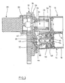
- Fig. 2
- zeigt die Anordnung von Fig. 1 mit geschlossener unterer Walze.
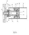
- Fig. 3
- zeigt die Anordnung nach Fig. 1 in einer ähnlichen Darstellung.
- Fig. 4
- zeigt einen Schnitt durch die untere Walze gemäß der Darstellung nach Fig. 1, jedoch mit einem Schnitt senkrecht zum Schnitt nach Fig. 1.
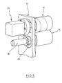
- Fig. 5
- zeigt perspektivisch eine zweite Ausführungsform eines Walzenpaars nach der Erfindung.
- In den Figuren 1 bis 4 ist eine Tragplatte 10 zu erkennen, die Bestandteil eines Maschinenrahmens einer Maschine ist, welche zur Aufbereitung eines sogenannten Filtertows dient. Zu dieser Anlage gehören zwei Paare von Walzen, von denen eines in den Figuren 1 bis 3 dargestellt ist. Das zweite Paar kann einen gleichen Aufbau haben oder herkömmlich ausgeführt sein.
- In den Figuren 1 bis 3 ist eine obere Walze 12 und eine untere Walze 14 zu erkennen. Die obere hohle Walze besteht aus Metall, während die untere Walze 14 einen hohlen Metallmantel 16 und einen Gummibelag 18 aufweist.
- Auf der linken Seite der vertikalen Tragplatte 10 ist ein Elektromotor 20 angeflanscht. Seine Antriebswelle 22 ist über eine Kupplung mit einer weiteren Welle 24 gekuppelt, die sich in einen hülsenförmigen Lagerkörper 26 hineinerstreckt. Der Lagerkörper 26 ist an ein Getriebegehäuse 28 angeflanscht, das zwei Stirnzahnräder 30, 32 aufnimmt. Das Stirnrad 30 sitzt auf der Welle 24 und kämmt mit dem zweiten Stirnrad 32. Das Übersetzungsverhältnis ist 1:1. Das Getriebegehäuse 28 ist fest mit der Tragplatte 10 verbunden.
- Die Welle 24 ist drehfest mit einem Flansch 34 verbunden, der seinerseits innerhalb der Walze 32 eingespannt ist. Eine Drehung der Welle 24 führt damit zu einer entsprechenden Drehung der Walze 12. Die Walze 12 ist nur an einer Stelle mittig gehalten. Die Lastaufnahme erfolgt über die Welle 24, die mit Hilfe von Wälzlagern 36, 38 innerhalb des Lagerkörpers 26 gelagert ist.
- Mit der Außenseite des Getriebegehäuses 30 ist ein Lagerflansch 40 durch Schraubbefestigung verbunden, der mittels zweier Wälzlager 42, 44 einen Zapfen 46 drehbar lagert, der drehfest mit dem unteren Stirnrad 32 verbunden ist.
- Mit Hilfe von zwei diametral gegenüberliegenden Lagerzapfen 48, 50 ist vom Lagerflansch 32 ein hülsenförmiges Lagerbauteil 50 schwenkbar gelagert. In den Figuren 1 bis 3 erfolgt diese Lagerung um eine horizontale Achse. Wie ferner aus Fig. 4 hervorgeht, lagert das hülsenförmige Lagerbauteil 50 mit Hilfe von zwei diametral gegenüberliegenden Lagerzapfen 52, 54 die inneren Ringe von zwei Wälzlagern 56, 58. Der äußere Ring der Lager 56, 58 ist drehfest mit der Innenseite der Walze 14 verbunden.
- Mit dem äußeren Ring der Wälzlager 56, 58 ist ein Flansch 60 verbunden, mit dem das rechte Ende einer Gelenkwelle 62 drehstarr gekoppelt ist. Die Gelenkwelle weist ein erstes Kreuzgelenk 64 und ein zweites Kreuzgelenk 66 auf, durch welch letzteres eine Anlenkung an den Zapfen 46 erfolgt. Wie erkennbar, erstreckt sich die Gelenkwelle 62 durch das Innere des hülsenförmigen Lagerbauteils 50. Deren Inneres ist durch eine Schutzmembran 68 gegenüber Eindringen von Schmutz geschützt.
- An das hülsenförmige Lagerbauteil 50 ist an der Unterseite ein winkelförmiges Bauteil 70 angeschraubt, das in Fig. 1 an einem Anschlag 72 anliegt, der mit dem Getriebegehäuse 28 verbunden ist. An dem unteren Schenkel des Bauteils 70 ist eine pneumatische Verstellzylinderanordnung 74 angelenkt. Mit Hilfe der Verstellzylinderanordnung 74 kann mithin die untere Walze nach oben geschwenkt werden, wie dies in Fig. 2 dargestellt ist. Der Druck, mit dem die beiden Walzen 12, 14 gegeneinander gepreßt werden, wird durch den Druck in der Zylinderanordnung 74 vorgegeben.
- Während des Betriebes, wie er in Fig. 2 dargestellt ist, wird nicht nur die obere Walze 12 angetrieben, sondern auch die untere Walze 14, und zwar synchron. Die beschriebene Lagerung der unteren Walze 14 ermöglicht jedoch im Betrieb ein Kippen der unteren Walze 14, wie dies in Fig. 3 dargestellt ist oder auch ein Kippen in die entgegengesetzte Richtung, wie dies in Fig. 3 dargestellt ist. Schließlich ist auch möglich, die Walze 14 über einen mehr oder weniger großen Spalt von der oberen Walze 12 zu entfernen. Dabei erstrecken sich die Längsachsen der Walzen 12, 14 parallel zueinander, während die Gelenkwelle 62 und auch das Lagerbauteil 50 nach unten geneigt sind. Der Antrieb der unteren Walze 14 erfolgt jedoch unverändert.
- Es sei noch erwähnt, daß statt der gezeigten Gelenkwelle auch andere gelenkige Wellen zum Einsatz kommen können oder eine einteilige in sich elastische Welle.
- Bei der Ausführungsform nach Fig. 5 werden wiederum zwei Walzen 12 und 14 verwendet vergleichbar den Walzen 12 und 14 nach den Fign. 1 bis 4. Die obere Walze 12 wird vom Elektromotor 20 angetrieben. Auch insoweit besteht Übereinstimmung mit der voran beschriebenen Ausführungsform. Die untere Walze 14 wird durch einen getrennten Druckluftmotor 80 angetrieben, der über eine Freilaufkupplung 82 an die untere Walze 14 gekoppelt ist. Der Druckluftmotor 80 wird mit einer Drehzahl angetrieben, die gewährleistet, daß beide Walzen 12, 14 die gleich Umfangsgeschwindigkeit haben. Das eingestellte Drehmoment des Druckluftmotors 80 kompensiert die Reibungsverluste der Lager. Die Schwenkbetätigung der unteren Walzen 14 kann auf gleiche Weise erfolgen wie zum obigen Ausführungsbeispiel beschrieben.
Claims (10)
- Walzenpaar zum Spannen von Strängen aus Filtermaterial bei der Herstellung von Zigarettenfiltern, mit einer ersten Walze aus Metall, die von einem Antrieb drehend angetrieben ist und einer zweiten Walze, deren Oberfläche aus elastischem Material besteht, wobei beide Walzen an einem Rahmen oder dergleichen einseitig gelagert sind und die zweite Walze um eine horizontale Achse senkrecht zu ihrer Längsachse von der ersten Walze fort und auf diese zu schwenkbar gelagert ist und einer Betätigungsvorrichtung zur Verschwenkung der zweiten Walze, dadurch gekennzeichnet, daß die zweite Walze (14) von einem Antrieb (20) über eine zweite Antriebswelle (46) und eine Gelenkwelle (62) antreibbar und so gelagert ist, daß die Größe des Spalts zwischen den Walzen (12, 14) in Anpassung an die Dicke des Materials über seine Länge veränderbar ist.
- Walzenpaar nach Anspruch 1, dadurch gekennzeichnet, daß die zweite Walze (14) über eine Kreuzgelenkwelle (62) an die zweite Antriebswelle (46) angekoppelt ist.
- Walzenpaar nach Anspruch 1 oder 2, dadurch gekennzeichnet, daß die zweite Antriebswelle (42) über ein Zahnradgetriebe (30, 32) an die erste Antriebswelle (22) gekoppelt ist.
- Walzenpaar nach einem der Ansprüche 1 bis 3, dadurch gekennzeichnet, daß die zweite Walze (14) hohl ist und innen einen Antriebsflansch (60) aufweist, der mittels eines Rollenlagers (56, 58) um eine horizontale Achse schwenkbar an einem hülsenförmigen Lagerbauteil (50) gelagert ist, durch den die Gelenkwelle (62) geführt ist und das seinerseits über eine horizontale Achse schwenkbar am Rahmen gelagert ist.
- Walzenpaar nach Anspruch 3 oder 4, dadurch gekennzeichnet, daß der Rahmen eine vertikale Tragplatte (10) aufweist, an der auf einer Seite ein Antriebsmotor (20) angeflanscht ist, auf der anderen Seite der Tragplatte (10) ein Getriebegehäuse (28) für das Zahnradgetriebe angebracht ist und die zweite Walze (14) an der Außenseite des Getriebegehäuses (28) schwenkbar gelagert ist.
- Walzenpaar nach einem der Ansprüche 3 bis 5, dadurch gekennzeichnet, daß das Zahnradgetriebe zwei Stirnräder (30, 32) aufweist.
- Walzenpaar nach Anspruch 1, dadurch gekennzeichnet, daß die zweite Walze (14) über einen getrennten zweiten Antrieb (80) angetrieben ist.
- Walzenpaar nach Anspruch 7, dadurch gekennzeichnet, daß ein Hydro- oder Pneumomotor (80) als zweiter Antrieb vorgesehen ist.
- Walzenpaar nach Anspruch 7 oder 8, dadurch gekennzeichnet, daß der zweite Antrieb (80) über eine Freilaufkupplung (82) an die zweite Walze (14) gekoppelt ist.
- Walzenpaar nach einem der Ansprüche 7 bis 9, dadurch gekennzeichnet, daß der zweite Antrieb (80) mit einem Drehmoment angetrieben ist, der die Reibungsverluste der Lager kompensiert.
Applications Claiming Priority (3)
| Application Number | Priority Date | Filing Date | Title |
|---|---|---|---|
| DE10227378A DE10227378B4 (de) | 2002-06-20 | 2002-06-20 | Walzenpaar zum Spannen von Strängen aus Filtermaterial |
| DE10227378 | 2002-06-20 | ||
| PCT/EP2003/005287 WO2004000046A1 (de) | 2002-06-20 | 2003-05-20 | Walzenpaar zum spannen von strängen aus filtermaterial |
Publications (2)
| Publication Number | Publication Date |
|---|---|
| EP1513421A1 EP1513421A1 (de) | 2005-03-16 |
| EP1513421B1 true EP1513421B1 (de) | 2006-08-09 |
Family
ID=29719259
Family Applications (1)
| Application Number | Title | Priority Date | Filing Date |
|---|---|---|---|
| EP03732427A Expired - Lifetime EP1513421B1 (de) | 2002-06-20 | 2003-05-20 | Walzenpaar zum spannen von strängen aus filtermaterial |
Country Status (7)
| Country | Link |
|---|---|
| US (1) | US7308735B2 (de) |
| EP (1) | EP1513421B1 (de) |
| AT (1) | ATE335413T1 (de) |
| AU (1) | AU2003238363A1 (de) |
| DE (2) | DE10227378B4 (de) |
| ES (1) | ES2266824T3 (de) |
| WO (1) | WO2004000046A1 (de) |
Families Citing this family (7)
| Publication number | Priority date | Publication date | Assignee | Title |
|---|---|---|---|---|
| DE10354924B4 (de) * | 2003-11-25 | 2024-01-18 | Körber Technologies Gmbh | Vorrichtung zum Aufbereiten von Filtertowmaterial sowie Vorrichtung zur Herstellung von Filtern |
| ITBO20050603A1 (it) * | 2005-10-07 | 2007-04-08 | Cnh Italia Spa | Frizione a bagno d'olio |
| ITBO20060165A1 (it) * | 2006-03-08 | 2007-09-09 | Gd Spa | Macchina per la produzione di filtri di sigarette. |
| DE102006049823A1 (de) * | 2006-10-19 | 2008-04-24 | Hauni Maschinenbau Ag | Vorrichtung und Verfahren zur Aufbereitung von Filtermaterial für Zigarettenfilter oder dergleichen |
| CN103453118A (zh) * | 2013-08-30 | 2013-12-18 | 湖北中烟工业有限责任公司 | 一种双轴承过定位装置 |
| CN105852205A (zh) * | 2016-04-28 | 2016-08-17 | 宜兴市新建烟机配件有限公司 | 一种用于香烟过滤嘴开松机上聚氨酯橡胶辊 |
| CH712427A1 (de) * | 2016-05-02 | 2017-11-15 | Rieter Ag Maschf | Streckwerk einer Textilmaschine. |
Family Cites Families (14)
| Publication number | Priority date | Publication date | Assignee | Title |
|---|---|---|---|---|
| US2790208A (en) | 1954-03-15 | 1957-04-30 | Eastman Kodak Co | Method and means for opening crimped continuous filament tow |
| GB974512A (en) * | 1960-06-17 | 1964-11-04 | Eastman Kodak Co | An improved process and apparatus for the manufacture of uniformly crimped filamentary tow |
| DE1280114B (de) | 1963-04-19 | 1968-10-10 | Kurashiki Rayon Co | Vorrichtung zum Auflockern eines gekraeuselten, durchgehenden Faserstranges fuer Zigarettenfilter |
| GB1132984A (en) * | 1965-04-01 | 1968-11-06 | Courtaulds Ltd | Process and apparatus for opening tow |
| NL7002258A (de) * | 1969-02-21 | 1970-08-25 | ||
| DE7016570U (de) * | 1970-05-02 | 1971-02-25 | Glanzstoff Ag | Verstellbares galettenabzugswerk. |
| CH557194A (de) * | 1972-10-28 | 1974-12-31 | Bellmer Geb Kg Maschf | Filterpresse. |
| US4759247A (en) * | 1987-10-22 | 1988-07-26 | Bernal Rotary Systems, Inc. | Rotary dies with adjustable cutter force |
| US5678774A (en) * | 1995-12-18 | 1997-10-21 | Etc. Industries Inc. | Fiberglass cutting apparatus and method |
| DE19712417A1 (de) * | 1997-03-25 | 1998-10-01 | Schaeffler Waelzlager Ohg | Andruckrolle für Textilmaschinen |
| DE10210357B4 (de) * | 2002-03-08 | 2005-12-22 | Voith Paper Patent Gmbh | Walzenanordnung |
| DE20309301U1 (de) * | 2003-06-13 | 2003-08-28 | Stowe Woodward AG, 33758 Schloß Holte-Stukenbrock | Breitstreckwalze |
| US7305739B2 (en) * | 2004-09-15 | 2007-12-11 | Celanese Acetate, Llc | Apparatus for tow opening |
| DE102005023992A1 (de) * | 2005-05-20 | 2006-11-23 | TRüTZSCHLER GMBH & CO. KG | Vorrichtung an einer Spinnereivorbereitungsmaschine, z.B. Karde, Krempel, Strecke, Kämmmaschine o.dgl., zum Ermitteln der Masse und/oder Masseschwankungen eines Fasermaterials, z.B. mindestens ein Faserband, Faservlies o.dgl., aus Baumwolle, Chemiefasern o. dgl. |
-
2002
- 2002-06-20 DE DE10227378A patent/DE10227378B4/de not_active Expired - Fee Related
-
2003
- 2003-05-20 AU AU2003238363A patent/AU2003238363A1/en not_active Abandoned
- 2003-05-20 US US10/518,130 patent/US7308735B2/en not_active Expired - Fee Related
- 2003-05-20 ES ES03732427T patent/ES2266824T3/es not_active Expired - Lifetime
- 2003-05-20 DE DE50304585T patent/DE50304585D1/de not_active Expired - Lifetime
- 2003-05-20 EP EP03732427A patent/EP1513421B1/de not_active Expired - Lifetime
- 2003-05-20 AT AT03732427T patent/ATE335413T1/de active
- 2003-05-20 WO PCT/EP2003/005287 patent/WO2004000046A1/de not_active Ceased
Also Published As
| Publication number | Publication date |
|---|---|
| ES2266824T3 (es) | 2007-03-01 |
| DE50304585D1 (de) | 2006-09-21 |
| WO2004000046A1 (de) | 2003-12-31 |
| AU2003238363A1 (en) | 2004-01-06 |
| DE10227378B4 (de) | 2008-07-17 |
| DE10227378A1 (de) | 2004-01-08 |
| US20060179615A1 (en) | 2006-08-17 |
| EP1513421A1 (de) | 2005-03-16 |
| US7308735B2 (en) | 2007-12-18 |
| ATE335413T1 (de) | 2006-09-15 |
Similar Documents
| Publication | Publication Date | Title |
|---|---|---|
| DE102006044610B4 (de) | Vorrichtung zum Schneiden und/oder Prägen eines Zuschnittes oder einer Materialbahn | |
| DE4440660A1 (de) | Trenneinrichtung zum Abtrennen perforierter Schlauchabschnitte | |
| DE4140876C2 (de) | Walzenpresse | |
| DE69214933T3 (de) | Rollenpresse | |
| EP2464256A1 (de) | Vorrichtung zum reinigen einer funktionsoberfläche zur führung oder behandlung einer materialbahn | |
| DD140655A5 (de) | Antrieb einer schaelmaschine fuer koernerfruechte | |
| EP1513421B1 (de) | Walzenpaar zum spannen von strängen aus filtermaterial | |
| EP0324070A2 (de) | Presse zum kontinuierlichen Herstellen von Span- und Faserplatten oder dergleichen | |
| DE2643017C3 (de) | Durchbiegungseinstellwalze für Papiermaschinen | |
| DE4019363C1 (en) | Roller drive for press - has torque supports connected directly on defined load lines | |
| DE19710530B4 (de) | Vorrichtung zur Erzeugung oder Weiterverarbeitung von Faserband | |
| CH687302A5 (de) | Längsschneideinrichtung für Bahnen. | |
| EP0232553A1 (de) | Einrichtung zum Aufwickeln eines kontinuierlich anfallenden Schuppenstromes von biegsamen Flächengebilden zu einem Wickel | |
| DE202011107220U1 (de) | Drahtfördervorrichtung | |
| EP0775525A1 (de) | Drehmomentabstützung | |
| DE2643018C3 (de) | Walzenpresse mit einer Durchbiegungseinstellwalze z.B. für Papiermaschinen | |
| DE1527643A1 (de) | Walzwerksvorrichtung | |
| DE3318944C2 (de) | Faserbandablegeeinrichtung für eine Karde, Strecke o. dgl. | |
| DE69409556T2 (de) | Rotierende Schneidvorrichtung | |
| CH639145A5 (de) | Einrichtung an einer zettelmaschine, zum ein- und ausheben des zettelbaumes und zum zustellen und gleichfoermigen anpressen der presswalze. | |
| EP1151819B1 (de) | Antriebskupplung für Trommelscheren | |
| EP1740309A1 (de) | Walzenstuhl | |
| DE4019919C2 (de) | Warenabzugvorrichtung für Webmaschinen | |
| DE2845030C2 (de) | Rollgang zum Fördern von Walzgut | |
| DE69430821T2 (de) | Breitenveränderbare walze |
Legal Events
| Date | Code | Title | Description |
|---|---|---|---|
| PUAI | Public reference made under article 153(3) epc to a published international application that has entered the european phase |
Free format text: ORIGINAL CODE: 0009012 |
|
| 17P | Request for examination filed |
Effective date: 20041230 |
|
| AK | Designated contracting states |
Kind code of ref document: A1 Designated state(s): AT BE BG CH CY CZ DE DK EE ES FI FR GB GR HU IE IT LI LU MC NL PT RO SE SI SK TR |
|
| AX | Request for extension of the european patent |
Extension state: AL LT LV MK |
|
| DAX | Request for extension of the european patent (deleted) | ||
| GRAP | Despatch of communication of intention to grant a patent |
Free format text: ORIGINAL CODE: EPIDOSNIGR1 |
|
| GRAS | Grant fee paid |
Free format text: ORIGINAL CODE: EPIDOSNIGR3 |
|
| GRAA | (expected) grant |
Free format text: ORIGINAL CODE: 0009210 |
|
| AK | Designated contracting states |
Kind code of ref document: B1 Designated state(s): AT BE BG CH CY CZ DE DK EE ES FI FR GB GR HU IE IT LI LU MC NL PT RO SE SI SK TR |
|
| PG25 | Lapsed in a contracting state [announced via postgrant information from national office to epo] |
Ref country code: IT Free format text: LAPSE BECAUSE OF FAILURE TO SUBMIT A TRANSLATION OF THE DESCRIPTION OR TO PAY THE FEE WITHIN THE PRESCRIBED TIME-LIMIT;WARNING: LAPSES OF ITALIAN PATENTS WITH EFFECTIVE DATE BEFORE 2007 MAY HAVE OCCURRED AT ANY TIME BEFORE 2007. THE CORRECT EFFECTIVE DATE MAY BE DIFFERENT FROM THE ONE RECORDED. Effective date: 20060809 Ref country code: CZ Free format text: LAPSE BECAUSE OF FAILURE TO SUBMIT A TRANSLATION OF THE DESCRIPTION OR TO PAY THE FEE WITHIN THE PRESCRIBED TIME-LIMIT Effective date: 20060809 Ref country code: SK Free format text: LAPSE BECAUSE OF FAILURE TO SUBMIT A TRANSLATION OF THE DESCRIPTION OR TO PAY THE FEE WITHIN THE PRESCRIBED TIME-LIMIT Effective date: 20060809 Ref country code: IE Free format text: LAPSE BECAUSE OF FAILURE TO SUBMIT A TRANSLATION OF THE DESCRIPTION OR TO PAY THE FEE WITHIN THE PRESCRIBED TIME-LIMIT Effective date: 20060809 Ref country code: FI Free format text: LAPSE BECAUSE OF FAILURE TO SUBMIT A TRANSLATION OF THE DESCRIPTION OR TO PAY THE FEE WITHIN THE PRESCRIBED TIME-LIMIT Effective date: 20060809 Ref country code: SI Free format text: LAPSE BECAUSE OF FAILURE TO SUBMIT A TRANSLATION OF THE DESCRIPTION OR TO PAY THE FEE WITHIN THE PRESCRIBED TIME-LIMIT Effective date: 20060809 Ref country code: RO Free format text: LAPSE BECAUSE OF FAILURE TO SUBMIT A TRANSLATION OF THE DESCRIPTION OR TO PAY THE FEE WITHIN THE PRESCRIBED TIME-LIMIT Effective date: 20060809 |
|
| REG | Reference to a national code |
Ref country code: GB Ref legal event code: FG4D Free format text: NOT ENGLISH |
|
| REG | Reference to a national code |
Ref country code: CH Ref legal event code: EP |
|
| REG | Reference to a national code |
Ref country code: IE Ref legal event code: FG4D Free format text: LANGUAGE OF EP DOCUMENT: GERMAN |
|
| REF | Corresponds to: |
Ref document number: 50304585 Country of ref document: DE Date of ref document: 20060921 Kind code of ref document: P |
|
| GBT | Gb: translation of ep patent filed (gb section 77(6)(a)/1977) |
Effective date: 20060913 |
|
| PG25 | Lapsed in a contracting state [announced via postgrant information from national office to epo] |
Ref country code: DK Free format text: LAPSE BECAUSE OF FAILURE TO SUBMIT A TRANSLATION OF THE DESCRIPTION OR TO PAY THE FEE WITHIN THE PRESCRIBED TIME-LIMIT Effective date: 20061109 Ref country code: BG Free format text: LAPSE BECAUSE OF FAILURE TO SUBMIT A TRANSLATION OF THE DESCRIPTION OR TO PAY THE FEE WITHIN THE PRESCRIBED TIME-LIMIT Effective date: 20061109 Ref country code: SE Free format text: LAPSE BECAUSE OF FAILURE TO SUBMIT A TRANSLATION OF THE DESCRIPTION OR TO PAY THE FEE WITHIN THE PRESCRIBED TIME-LIMIT Effective date: 20061109 |
|
| PG25 | Lapsed in a contracting state [announced via postgrant information from national office to epo] |
Ref country code: PT Free format text: LAPSE BECAUSE OF FAILURE TO SUBMIT A TRANSLATION OF THE DESCRIPTION OR TO PAY THE FEE WITHIN THE PRESCRIBED TIME-LIMIT Effective date: 20070109 |
|
| REG | Reference to a national code |
Ref country code: ES Ref legal event code: FG2A Ref document number: 2266824 Country of ref document: ES Kind code of ref document: T3 |
|
| ET | Fr: translation filed | ||
| REG | Reference to a national code |
Ref country code: IE Ref legal event code: FD4D |
|
| PLBE | No opposition filed within time limit |
Free format text: ORIGINAL CODE: 0009261 |
|
| STAA | Information on the status of an ep patent application or granted ep patent |
Free format text: STATUS: NO OPPOSITION FILED WITHIN TIME LIMIT |
|
| 26N | No opposition filed |
Effective date: 20070510 |
|
| REG | Reference to a national code |
Ref country code: CH Ref legal event code: PL |
|
| PG25 | Lapsed in a contracting state [announced via postgrant information from national office to epo] |
Ref country code: MC Free format text: LAPSE BECAUSE OF NON-PAYMENT OF DUE FEES Effective date: 20070531 |
|
| PG25 | Lapsed in a contracting state [announced via postgrant information from national office to epo] |
Ref country code: CH Free format text: LAPSE BECAUSE OF NON-PAYMENT OF DUE FEES Effective date: 20070531 Ref country code: LI Free format text: LAPSE BECAUSE OF NON-PAYMENT OF DUE FEES Effective date: 20070531 |
|
| PG25 | Lapsed in a contracting state [announced via postgrant information from national office to epo] |
Ref country code: GR Free format text: LAPSE BECAUSE OF FAILURE TO SUBMIT A TRANSLATION OF THE DESCRIPTION OR TO PAY THE FEE WITHIN THE PRESCRIBED TIME-LIMIT Effective date: 20061110 |
|
| PG25 | Lapsed in a contracting state [announced via postgrant information from national office to epo] |
Ref country code: EE Free format text: LAPSE BECAUSE OF FAILURE TO SUBMIT A TRANSLATION OF THE DESCRIPTION OR TO PAY THE FEE WITHIN THE PRESCRIBED TIME-LIMIT Effective date: 20060809 |
|
| PGFP | Annual fee paid to national office [announced via postgrant information from national office to epo] |
Ref country code: BE Payment date: 20090310 Year of fee payment: 7 |
|
| PG25 | Lapsed in a contracting state [announced via postgrant information from national office to epo] |
Ref country code: LU Free format text: LAPSE BECAUSE OF NON-PAYMENT OF DUE FEES Effective date: 20070520 Ref country code: CY Free format text: LAPSE BECAUSE OF FAILURE TO SUBMIT A TRANSLATION OF THE DESCRIPTION OR TO PAY THE FEE WITHIN THE PRESCRIBED TIME-LIMIT Effective date: 20060809 |
|
| PG25 | Lapsed in a contracting state [announced via postgrant information from national office to epo] |
Ref country code: TR Free format text: LAPSE BECAUSE OF FAILURE TO SUBMIT A TRANSLATION OF THE DESCRIPTION OR TO PAY THE FEE WITHIN THE PRESCRIBED TIME-LIMIT Effective date: 20060809 Ref country code: HU Free format text: LAPSE BECAUSE OF FAILURE TO SUBMIT A TRANSLATION OF THE DESCRIPTION OR TO PAY THE FEE WITHIN THE PRESCRIBED TIME-LIMIT Effective date: 20070210 |
|
| BERE | Be: lapsed |
Owner name: *INTERNATIONAL TOBACCO MACHINERY B.V. Effective date: 20100531 |
|
| PG25 | Lapsed in a contracting state [announced via postgrant information from national office to epo] |
Ref country code: BE Free format text: LAPSE BECAUSE OF NON-PAYMENT OF DUE FEES Effective date: 20100531 |
|
| PGFP | Annual fee paid to national office [announced via postgrant information from national office to epo] |
Ref country code: GB Payment date: 20140520 Year of fee payment: 12 |
|
| PGFP | Annual fee paid to national office [announced via postgrant information from national office to epo] |
Ref country code: ES Payment date: 20140521 Year of fee payment: 12 Ref country code: NL Payment date: 20140520 Year of fee payment: 12 Ref country code: AT Payment date: 20140519 Year of fee payment: 12 Ref country code: FR Payment date: 20140516 Year of fee payment: 12 Ref country code: IT Payment date: 20140528 Year of fee payment: 12 |
|
| PGFP | Annual fee paid to national office [announced via postgrant information from national office to epo] |
Ref country code: DE Payment date: 20140708 Year of fee payment: 12 |
|
| REG | Reference to a national code |
Ref country code: DE Ref legal event code: R119 Ref document number: 50304585 Country of ref document: DE |
|
| REG | Reference to a national code |
Ref country code: AT Ref legal event code: MM01 Ref document number: 335413 Country of ref document: AT Kind code of ref document: T Effective date: 20150520 |
|
| GBPC | Gb: european patent ceased through non-payment of renewal fee |
Effective date: 20150520 |
|
| PG25 | Lapsed in a contracting state [announced via postgrant information from national office to epo] |
Ref country code: IT Free format text: LAPSE BECAUSE OF NON-PAYMENT OF DUE FEES Effective date: 20150520 |
|
| REG | Reference to a national code |
Ref country code: NL Ref legal event code: MM Effective date: 20150601 |
|
| REG | Reference to a national code |
Ref country code: FR Ref legal event code: ST Effective date: 20160129 |
|
| PG25 | Lapsed in a contracting state [announced via postgrant information from national office to epo] |
Ref country code: AT Free format text: LAPSE BECAUSE OF NON-PAYMENT OF DUE FEES Effective date: 20150520 |
|
| PG25 | Lapsed in a contracting state [announced via postgrant information from national office to epo] |
Ref country code: NL Free format text: LAPSE BECAUSE OF NON-PAYMENT OF DUE FEES Effective date: 20150601 Ref country code: GB Free format text: LAPSE BECAUSE OF NON-PAYMENT OF DUE FEES Effective date: 20150520 Ref country code: DE Free format text: LAPSE BECAUSE OF NON-PAYMENT OF DUE FEES Effective date: 20151201 |
|
| PG25 | Lapsed in a contracting state [announced via postgrant information from national office to epo] |
Ref country code: FR Free format text: LAPSE BECAUSE OF NON-PAYMENT OF DUE FEES Effective date: 20150601 |
|
| REG | Reference to a national code |
Ref country code: ES Ref legal event code: FD2A Effective date: 20160629 |
|
| PG25 | Lapsed in a contracting state [announced via postgrant information from national office to epo] |
Ref country code: ES Free format text: LAPSE BECAUSE OF NON-PAYMENT OF DUE FEES Effective date: 20150521 |