EP1513242B1 - Klauenpol-Schrittmotor - Google Patents
Klauenpol-Schrittmotor Download PDFInfo
- Publication number
- EP1513242B1 EP1513242B1 EP04255288A EP04255288A EP1513242B1 EP 1513242 B1 EP1513242 B1 EP 1513242B1 EP 04255288 A EP04255288 A EP 04255288A EP 04255288 A EP04255288 A EP 04255288A EP 1513242 B1 EP1513242 B1 EP 1513242B1
- Authority
- EP
- European Patent Office
- Prior art keywords
- bobbin
- stator
- magnet wire
- cover ring
- magnet
- Prior art date
- Legal status (The legal status is an assumption and is not a legal conclusion. Google has not performed a legal analysis and makes no representation as to the accuracy of the status listed.)
- Expired - Lifetime
Links
- 239000011347 resin Substances 0.000 claims description 16
- 229920005989 resin Polymers 0.000 claims description 16
- 238000003491 array Methods 0.000 claims description 4
- 239000007787 solid Substances 0.000 claims description 3
- 238000000465 moulding Methods 0.000 description 14
- 239000000470 constituent Substances 0.000 description 5
- 238000000034 method Methods 0.000 description 5
- 230000008569 process Effects 0.000 description 5
- 230000007246 mechanism Effects 0.000 description 3
- 229920000106 Liquid crystal polymer Polymers 0.000 description 2
- 239000004977 Liquid-crystal polymers (LCPs) Substances 0.000 description 2
- 229910000831 Steel Inorganic materials 0.000 description 2
- 230000002542 deteriorative effect Effects 0.000 description 2
- 238000004519 manufacturing process Methods 0.000 description 2
- 239000003550 marker Substances 0.000 description 2
- 239000000463 material Substances 0.000 description 2
- 230000009467 reduction Effects 0.000 description 2
- 239000000243 solution Substances 0.000 description 2
- 239000010935 stainless steel Substances 0.000 description 2
- 229910001220 stainless steel Inorganic materials 0.000 description 2
- 239000010959 steel Substances 0.000 description 2
- 238000004804 winding Methods 0.000 description 2
- 229910000976 Electrical steel Inorganic materials 0.000 description 1
- 229910001335 Galvanized steel Inorganic materials 0.000 description 1
- XUIMIQQOPSSXEZ-UHFFFAOYSA-N Silicon Chemical compound [Si] XUIMIQQOPSSXEZ-UHFFFAOYSA-N 0.000 description 1
- 239000011248 coating agent Substances 0.000 description 1
- 238000000576 coating method Methods 0.000 description 1
- 230000003247 decreasing effect Effects 0.000 description 1
- 230000006866 deterioration Effects 0.000 description 1
- 230000002708 enhancing effect Effects 0.000 description 1
- 239000008397 galvanized steel Substances 0.000 description 1
- 238000001746 injection moulding Methods 0.000 description 1
- 230000010354 integration Effects 0.000 description 1
- 230000004048 modification Effects 0.000 description 1
- 238000012986 modification Methods 0.000 description 1
- 229910052761 rare earth metal Inorganic materials 0.000 description 1
- 150000002910 rare earth metals Chemical class 0.000 description 1
- 229910052710 silicon Inorganic materials 0.000 description 1
- 239000010703 silicon Substances 0.000 description 1
- 238000007711 solidification Methods 0.000 description 1
- 230000008023 solidification Effects 0.000 description 1
- 230000001360 synchronised effect Effects 0.000 description 1
Images


Classifications
-
- H—ELECTRICITY
- H02—GENERATION; CONVERSION OR DISTRIBUTION OF ELECTRIC POWER
- H02K—DYNAMO-ELECTRIC MACHINES
- H02K1/00—Details of the magnetic circuit
- H02K1/06—Details of the magnetic circuit characterised by the shape, form or construction
- H02K1/12—Stationary parts of the magnetic circuit
- H02K1/14—Stator cores with salient poles
- H02K1/145—Stator cores with salient poles having an annular coil, e.g. of the claw-pole type
-
- H—ELECTRICITY
- H02—GENERATION; CONVERSION OR DISTRIBUTION OF ELECTRIC POWER
- H02K—DYNAMO-ELECTRIC MACHINES
- H02K3/00—Details of windings
- H02K3/46—Fastening of windings on the stator or rotor structure
- H02K3/52—Fastening salient pole windings or connections thereto
- H02K3/521—Fastening salient pole windings or connections thereto applicable to stators only
- H02K3/525—Annular coils, e.g. for cores of the claw-pole type
-
- H—ELECTRICITY
- H02—GENERATION; CONVERSION OR DISTRIBUTION OF ELECTRIC POWER
- H02K—DYNAMO-ELECTRIC MACHINES
- H02K37/00—Motors with rotor rotating step by step and without interrupter or commutator driven by the rotor, e.g. stepping motors
- H02K37/10—Motors with rotor rotating step by step and without interrupter or commutator driven by the rotor, e.g. stepping motors of permanent magnet type
- H02K37/12—Motors with rotor rotating step by step and without interrupter or commutator driven by the rotor, e.g. stepping motors of permanent magnet type with stationary armatures and rotating magnets
- H02K37/125—Magnet axially facing armature
-
- H—ELECTRICITY
- H02—GENERATION; CONVERSION OR DISTRIBUTION OF ELECTRIC POWER
- H02K—DYNAMO-ELECTRIC MACHINES
- H02K37/00—Motors with rotor rotating step by step and without interrupter or commutator driven by the rotor, e.g. stepping motors
- H02K37/10—Motors with rotor rotating step by step and without interrupter or commutator driven by the rotor, e.g. stepping motors of permanent magnet type
- H02K37/12—Motors with rotor rotating step by step and without interrupter or commutator driven by the rotor, e.g. stepping motors of permanent magnet type with stationary armatures and rotating magnets
- H02K37/14—Motors with rotor rotating step by step and without interrupter or commutator driven by the rotor, e.g. stepping motors of permanent magnet type with stationary armatures and rotating magnets with magnets rotating within the armatures
-
- H—ELECTRICITY
- H02—GENERATION; CONVERSION OR DISTRIBUTION OF ELECTRIC POWER
- H02K—DYNAMO-ELECTRIC MACHINES
- H02K5/00—Casings; Enclosures; Supports
-
- H—ELECTRICITY
- H02—GENERATION; CONVERSION OR DISTRIBUTION OF ELECTRIC POWER
- H02K—DYNAMO-ELECTRIC MACHINES
- H02K5/00—Casings; Enclosures; Supports
- H02K5/04—Casings or enclosures characterised by the shape, form or construction thereof
- H02K5/15—Mounting arrangements for bearing-shields or end plates
-
- H—ELECTRICITY
- H02—GENERATION; CONVERSION OR DISTRIBUTION OF ELECTRIC POWER
- H02K—DYNAMO-ELECTRIC MACHINES
- H02K5/00—Casings; Enclosures; Supports
- H02K5/04—Casings or enclosures characterised by the shape, form or construction thereof
- H02K5/22—Auxiliary parts of casings not covered by groups H02K5/06-H02K5/20, e.g. shaped to form connection boxes or terminal boxes
- H02K5/225—Terminal boxes or connection arrangements
Definitions
- the present invention relates to a structure of a claw-pole type stepping motor, and particularly to a structure thereof for achieving reduction in dimension and offering technical advantages.
- A-phase and B-phase driving coils are typically disposed so as to surround the outer circumference of a rotor.
- the diameter of a rotor magnet is restricted by the inner diameter of a stator, so a motor with a smaller dimension is forced to have a rotor magnet with a smaller diameter thus resulting in significant deterioration in motor characteristic.
- a brushless DC motor equipped with an encoder as a position detector must be used in place of a claw-pole type stepping motor, which inevitably pushes up production cost.
- Japanese Patent Application Laid-Open No. 2003-009497 discloses a motor structured such that driving coils are disposed so as to axially sandwich a rotor magnet.
- This motor structure helps reduction of its radial dimension, but since the motor is entirely covered by a case, the motor size has to be increased for the thickness of the case in all directional dimensions including the radial dimension. In order to reduce the radial dimension of this motor, the thickness of the case must be decreased. A case with a small thickness is technically difficult to fabricate, and also is inferior in mechanical strength, thus effort in reducing the thickness of the case has its limit.
- JP-A-10 327570 on which the preamble of the independent claim is based discloses a claw-pole stepping motor with a cylindrical rotor assembly and cup-shaped stator units which are co-axially coupled and include a bobbin.
- US-A-2 922 932 discloses a bobbin for a synchronous electric motor having a ring-shaped cover for the winding and the bobbin terminal block.
- EP-A-1 394 922 discloses a claw-pole stepping motor with a rotor and pair of units having a wound bobbin and a cover ring which protects the coil during moulding.
- the present invention has been made in light of the above circumstances, and it is an object of the present invention to overcome the difficulty in resin-molding a stator to thereby eliminate a motor case for a claw-pole type stepping motor in order to downsize its radial dimension while maintaining its mechanical strength.
- the present invention provides a claw-pole type stepping motor comprising a rotor assembly and two cup-shaped stator units.
- the rotor assembly is shaped substantially cylindrical and has a rotor magnet and a rotary shaft at its center.
- the two cup-shaped stator units each comprise a bobbin having two flanges, a coil with a magnet wire wound around the bobbin between the two flanges of the bobbin and two stator yokes positioned on opposite sides of the bobbin and magnetically connected to each other, the stator yokes having respective pole tooth arrays which are shifted in phase from each other by an electrical angle of 180 degrees, which extend from the respective yoke in the same direction and which project axially beyond the same side of the bobbin.
- the stator units are coupled to each other coaxially so as to axially sandwich the rotor magnet with their coils located respectively toward both axial end faces of the rotor magnet and their pole tooth arrays surrounding the rotor magnet.
- Each of the stator units further includes a cover ring which is in contact with the two flanges of the bobbin so as to protect the magnet wire wound around the bobbin against resin injected when the stator unit is resin molded for an integrated solid structure.
- the bobbin includes a terminal block provided with terminals to conduct supply current to the magnet wire, and the cover ring includes a guide block which is at least partly in touch with the terminal block so as to protect end portions of the magnet wire leading out to the terminals against the resin injected.
- the cover ring is in contact with the two flanges such that the cover ring touches an outer circumference of each of the two flanges so as to protect the magnet wire wound between the two flanges against the resin injected. Consequently, the resin injected is prevented from getting to the magnet wire wound around the bobbin, and also the bobbin and the cover ring are held coaxial to each other when positioned.
- the bobbin includes a terminal block provided with terminals to conduct supply current to the magnet wire, and the cover ring includes a guide block which is at least partly in touch with the terminal block so as to protect the end portions of the magnet wire leading out to the terminals against the resin injected. Consequently, the bobbin is stopped from moving in the axial direction due to molding pressure at the time of resin-molding the stator unit for an integrated structure.
- the guide block of the cover ring may have a groove which allows the magnet wire to lead out to the terminals. Consequently, the stator unit is resin-molded with a guide passage ensured for leading out the magnet wire to the terminals.
- stator units structured as described above are coupled to each other, pins may be inserted though respective holes formed on the stator units when resin-molded and riveted for fixation, a sufficient strength is provided for the motor assembled.
- a stepping motor according to the present invention comprises two stator units, specifically an A-phase stator unit and a B-phase stator unit arranged coaxially to each other.
- the B-phase stator unit is shown in Fig. 1 in an exploded manner so as to explain its constituent parts.
- the A-phase stator unit uses common constituent parts to the B-phase stator unit and an explanation thereof will be omitted. Since the A-phase and B-phase stator units use common constituent parts, the production cost of the parts can be reduced.
- the B-phase stator includes a bearing 11, a first stator yoke 12, a cover ring 13, a bobbin 14, a core 15, and a second stator yoke 16.
- the bearing 11 is, for example, a sintered sleeve bearing to rotatably support a rotary shaft of a rotor assembly to be described later.
- the first and second stator yokes 12 and 16 are punched out of a soft magnetic plate, such as a galvanized steel plate (SECC), a silicon steel plate, and an electromagnetic soft steel (SUY), have respective pole teeth 12a and 16a, are magnetically connected to each other via the core 15, and are coupled to each other with the respective pole teeth 12a and 16a shifted in phase from each other by an electrical angle of 180 degrees.
- the second stator yoke 16 has a pit 16b which engages with a boss 14b provided on the bobbin 14, whereby the second stator yoke 16 and the bobbin 14 are duly positioned with respect to each other in a circumferential direction for resin-molding process.
- the core 15 is formed of a soft magnetic plate, such as an SECC, a silicon plate steel, and an SUY, and has a center hole for allowing the rotary shaft of the rotor assembly to pass through.
- a soft magnetic plate such as an SECC, a silicon plate steel, and an SUY
- the bobbin 14 is formed of, for example, liquid crystal polymer, and made up of a body section 14a, flanges 14a' and 14a" sandwiching the body section 14a, and a terminal block 14c.
- a magnet wire 14d is wound around the body section 14a between the flanges 14a' and 14a", and terminal pins 14e for supplying current to the magnet wire 14d are attached to the terminal block 14c.
- the bobbin 14 is provided with the aforementioned boss 14b which fits engagingly into the aforementioned pit 16b of the second stator yoke 16 for positioning function as mentioned above.
- the mechanism for positioning the bobbin 14 with respect to the second stator yoke 16 may alternatively be structured such that the second stator yoke 16 is provided with a boss while the bobbin 14 is provided with a pit, or may be constituted by means of a positioning marker, such as a notch, provided appropriately.
- the terminal block 14c has a groove 14f which functions mainly as a mechanism for hooking the magnet wire 14d when the magnet wire 14d is wound around the bobbin 14.
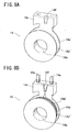
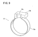
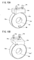
- the cover ring 13 is formed of, for example, liquid crystal polymer, made up of a body section 13a and a guide block 13b, and protects the magnet wire 14d wound around the bobbin 14 against resin injected for molding the B-phase stator unit for integrated structure.
- the guide block 13b has a groove 13c which allows the terminal ends of the magnet wire 14d wound around the bobbin 14 to lead out to the terminal pins 14e when the cover ring 13 is attached onto the bobbin 14 thereby bringing the guide block 13b in contact with the terminal block 14c.
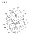
- the B-phase stator unit is framed as shown in Fig. 2 .
- the guide block 13b of the cover ring 13 and the terminal block 14c of the bobbin 14 are engagingly sandwiched between two adjacent pole teeth out of the pole teeth 12a of the first stator yoke 12, whereby the cover ring 13 and the bobbin 14 can be duly positioned with respect to the first stator yoke 12 in the circumferential direction.
- the bobbin 14 can be duly positioned with respect to the second stator yoke 16 in the circumferential direction by means of the boss 14b of the bobbin 14 engagingly fitting into the pit 16b of the second stator yoke 16 as described above.
- the B-phase stator units framed as shown in Fig. 2 is resin-molded by, for example, injection molding to be integrated for solidification.
- a claw-pole type stepping motor 1 according to a preferred embodiment of the present invention comprises the above-described B-phase stator unit 10 resin-molded, the aforementioned A-phase stator unit 20 resin-molded, a rotor assembly 30, a front plate 36, a rear plate 37, and pins 34 and 35 for securely holding together the parts in place.
- the B-phase stator unit 10 is resin-molded as described above so as to have a resin portion 17, and holes 17a for passing the pins 34 and 35 are formed in the resin portion 17 at the time of resin-molding.
- the A-phase stator unit 20 is structured in the same way as the B-phase stator unit 10 with only difference found in the location of the holes for passing the pins 34 and 35, and therefore a detailed explanation thereof is omitted.
- the rotor assembly 30 includes a rotor magnet 31 constituted by, for example, a rare-earth cylindrical magnet and having a outer diameter of some 5 mm, and a rotary shaft 33 formed of, for example, stainless steel, and washers 32 formed of, for example, stainless steel are put on the rotary shaft 33.
- the front plate 36 which may be formed of a magnetic or nonmagnetic material, has holes 36a for passing the pins 34 and 35, and the pins 34 and 35 are, for example, riveted to be fixed at the holes 36a.
- the rear plate 37 which may also be formed of a magnetic or nonmagnetic material, has holes 37a for passing the pins 34 and 35, and the pins 34 and 35 are, for example, riveted to be fixed at the holes 37a.
- the motor 1 is assembled such that the constituent parts described above are put together in an axial direction in reference-numerical order.
- the pins 34 and 35 are inserted through respective holes 36a of the front plate 36, the A-phase stator unit 20, the B-phase stator unit 10, and the rear plate 37, and have their respective both ends, for example, riveted for fixation, whereby the parts are duly and fixedly positioned with respect to one another in the circumferential direction.
- the motor 1 has the rotary shaft 33 disposed at the center, and the rotor magnet 31 is mounted on the rotary shaft 33.
- the body section 13a of the cover ring 13 is disposed so as to be in contact with the flanges 14a' and 14a" of the bobbin 14 which sandwich the magnet wire 14d wound around the bobbin 14, and prevents injected resin from getting to the magnet wire 14d. This way, the magnet wire 14d is protected against the injected resin and therefore prevented from deteriorating or breaking when the stator units are resin-molded for integration.
- the cover ring 13 is put on the bobbin 14 preferably with the body section 13a set in touch with the outer circumference of at least one of the flanges 14a' and 14a", so that the cover ring 13 is held coaxial to the bobbin 14.
- the guide block 13b of the cover ring 13 is at least partly in touch with the terminal block 14c of the bobbin 14, whereby the injected resin is prevented from getting to the end portions of the magnet wire 14d leading out to the terminal pins 14e, and whereby the terminal block 14c is stopped from moving in the axial direction due to molding pressure at the process of resin-molding.
- the groove 13c provided at the guide block 13b allows the magnet wire 14d wound around the bobbin 14 to lead out to the terminal pins 14e.
- the motor 1 shown in Fig. 4 is perspectively viewed from its rear side, omitting the rear plate 37, the B-phase stator unit 10, the rotor assembly 30, and the washers 32.
- the boss 14b of the bobbin 14 fits engagingly into the pit 16b of the second stator yoke 16 so as to fixedly position the bobbin 14 with respect to the second stator yoke 16 in the circumferential direction.
- the positioning may alternatively be implemented, for example, such that a notch provided on the second stator yoke 16 in place of the pit 16b is set to a predetermined marker at the process of resin-molding.
- the groove 14f which is formed on the terminal block 14c of the bobbin 14, and which is intended to serve as a hooking mechanism for the magnet wire 14d at the process of winding, works, together with the groove 13c of the guide block 13b of the cover ring 13, also as a guide passage for the end portions of the magnet wire 14d leading to the terminal pins 14e, thus the magnet wire 14d is surely and reliably allowed to lead out to the terminal pins 14e.
- Fig. 7 shows that the motor 1 structured according to a preferred embodiment of the present invention is downsized so as to measure as small as 6 mm in height.
- the bridging portion between the flange 14a' and the terminal block 14c on the bobbin 14 has a width adapted to fit engagingly between two adjacent pole teeth of the pole teeth 12a of the first stator yoke 12 thereby fixedly positioning the bobbin 14 with respect to the first stator yoke 12 in the circumferential direction.
- the bridging portion between the body section 13a and the guide block 13b on the ring cover 13 has a width adapted to fit engagingly between the two adjacent pole teeth of the pole teeth 12a of the first stator yoke 12 thereby fixedly positioning the cover ring 13 with respect to the first stator yoke 12 in the circumferential direction.
- the cover ring 13 is put on the bobbin 14 such that the body section 13a covers the outer circumferences of the flanges 14a' and 14a", whereby the magnet wire 14d wound around the body section 14a between the flanges 14a' and 14a" is protected.
- the motor according to the present invention may have a round, rectangular or otherwise configured radial cross section according to a housing space configuration.
Landscapes
- Engineering & Computer Science (AREA)
- Power Engineering (AREA)
- Insulation, Fastening Of Motor, Generator Windings (AREA)
- Motor Or Generator Frames (AREA)
- Iron Core Of Rotating Electric Machines (AREA)
Claims (2)
- Klauenpol-Schrittmotor, umfassend:eine Rotoranordnung (30), die eine im Wesentlichen zylindrische Form hat, und die einen Rotormagneten (31) und eine drehbare Welle (33) in ihrer Mitte aufweist; undzwei becherförmige Statoreinheiten (10, 20), wobei jede umfasst:eine Trommel (14) mit zwei Flanschen (14a', 14a");eine Wicklung mit einem Kupferlackdraht (14d), der zwischen den zwei Flanschen der Trommel (14) um die Trommel (14) gewickelt ist; undzwei Statorbügel (12, 16), die auf gegenüberliegenden Seiten der Trommel positioniert sind und magnetisch miteinander verbunden sind, wobei die Statorbügel (12, 16) jeweilige Polzahnanordnungen (12a, 26a) haben, die mit einem elektrischen Winkel von 180 Grad voneinander phasenverschoben sind, die sich vom jeweiligen Bügel aus in dieselbe Richtung erstrecken und die axial über dieselbe Seite der Trommel (14) hinausragen;wobei die Statoreinheiten (10, 20) koaxial miteinander gekoppelt sind, so dass sie den Rotormagneten (31) axial einkeilen, wobei deren Trommeln jeweils in Richtung der beiden Axialendflächen des Rotormagneten (31) liegen und ihre Polzahnanordnungen (12a, 16a) den Rotormagneten (31) umgeben;dadurch gekennzeichnet, dass:die Trommel (14) einen Anschlussblock (14c) einschliesst, der mit Anschlüssen (14e) versehen ist, um Stromversorgung an den Kupferlackdraht zu leiten;jede der Statoreinheiten (10, 20) ferner einen Abdeckring (13) einschliesst, der mit den zwei Flanschen der Trommel (14) in Kontakt steht, um den um die Trommel (14) gewundenen Kupferlackdraht (14d) gegen Harz zu schützen, das injiziert wird, wenn die Statoreinheit (10, 20) für eine integrierte solide Struktur harzgeformt ist; etder Abdeckring (13) einen Führungsschlitten (13b) umfasst, der so angeordnet ist, dass er mindestens teilweise mit dem Anschlussblock (14c) in Verbindung steht, um so Endteile des Kupferlackdrahts, die zu den Anschlüssen (14e) hinausführen, gegen das injizierte Harz zu schützen;wobei der Abdeckring (13) mit einem äusseren Umfang von jedem der zwei Flanschen in Kontakt steht.
- Klauenpol-Schrittmotor nach Anspruch 1, wobei der Führungsschlitten (13b) des Abdeckrings (13) eine Rille hat, die es dem Kupferlackdraht ermöglicht zu den Anschlüssen hinauszuführen.
Applications Claiming Priority (2)
| Application Number | Priority Date | Filing Date | Title |
|---|---|---|---|
| JP2003310329 | 2003-09-02 | ||
| JP2003310329A JP3825024B2 (ja) | 2003-09-02 | 2003-09-02 | クローポール型ステッピングモータ |
Publications (2)
| Publication Number | Publication Date |
|---|---|
| EP1513242A1 EP1513242A1 (de) | 2005-03-09 |
| EP1513242B1 true EP1513242B1 (de) | 2008-11-26 |
Family
ID=34131818
Family Applications (1)
| Application Number | Title | Priority Date | Filing Date |
|---|---|---|---|
| EP04255288A Expired - Lifetime EP1513242B1 (de) | 2003-09-02 | 2004-09-01 | Klauenpol-Schrittmotor |
Country Status (4)
| Country | Link |
|---|---|
| US (1) | US7071593B2 (de) |
| EP (1) | EP1513242B1 (de) |
| JP (1) | JP3825024B2 (de) |
| DE (1) | DE602004017944D1 (de) |
Families Citing this family (39)
| Publication number | Priority date | Publication date | Assignee | Title |
|---|---|---|---|---|
| JP3515511B2 (ja) * | 2000-10-30 | 2004-04-05 | 三菱電機株式会社 | 電磁機器 |
| US7446442B2 (en) * | 2004-04-21 | 2008-11-04 | Canon Kabushiki Kaisha | Stepping motor and drive device |
| JP4297037B2 (ja) * | 2004-11-11 | 2009-07-15 | 株式会社デンソー | ステッピングモータ |
| JP4684689B2 (ja) * | 2005-03-14 | 2011-05-18 | 日本電産サンキョー株式会社 | ステッピングモータ |
| JP2006296086A (ja) * | 2005-04-11 | 2006-10-26 | Minebea-Matsushita Motor Corp | リードスクリュウ付きステッピングモータ |
| KR100811956B1 (ko) * | 2005-07-05 | 2008-03-10 | 엘지이노텍 주식회사 | 스텝핑 모터의 보빈 구조 |
| CN1945944A (zh) * | 2005-10-09 | 2007-04-11 | 精工电子有限公司 | 步进电机及电子器械 |
| CN1945943B (zh) * | 2005-10-09 | 2011-02-09 | 精工电子有限公司 | 步进电机及电子器械 |
| DE102006021247B4 (de) * | 2006-04-28 | 2012-02-02 | Bühler Motor GmbH | Elektromotor |
| DE102006026719B4 (de) * | 2006-06-08 | 2012-04-26 | Minebea Co., Ltd. | Klauenpolstator für einen Schrittmotor und Klauenpol-Schrittmotor |
| US20080024022A1 (en) * | 2006-07-26 | 2008-01-31 | Chun-Pin Wu | Motor wiring seat for a motor |
| JP4815299B2 (ja) * | 2006-07-31 | 2011-11-16 | 日本電産サンキョー株式会社 | モータ及びその製造方法 |
| JP2008263691A (ja) * | 2007-04-11 | 2008-10-30 | Minebea Co Ltd | 小径ステッピングモータ、そのボビン、及びそのモータの組立方法 |
| WO2008141214A1 (en) * | 2007-05-09 | 2008-11-20 | Motor Excellence, Llc. | Electrical output generating devices and driven electrical devices with reduced flux leakage using permanent magnet components, and methods of making and using the same |
| US7973446B2 (en) * | 2007-05-09 | 2011-07-05 | Motor Excellence, Llc | Electrical devices having tape wound core laminate rotor or stator elements |
| JP2010530729A (ja) * | 2007-06-19 | 2010-09-09 | エルジー イノテック カンパニー リミテッド | ステッピングモータ |
| JP5172225B2 (ja) * | 2007-06-21 | 2013-03-27 | ミネベア株式会社 | Pm型ステッピングモータ |
| CN201153222Y (zh) * | 2007-12-17 | 2008-11-19 | 上海鸣志电器有限公司 | 步进马达极爪 |
| EP2342803A2 (de) | 2008-11-03 | 2011-07-13 | Motor Excellence, LLC | Rotorentwürfe für ein quer- oder mischflusssystem |
| WO2010110575A2 (ko) * | 2009-03-23 | 2010-09-30 | 엘지이노텍 주식회사 | 스테핑 모터 |
| CN101901661B (zh) * | 2009-05-26 | 2011-12-21 | 浙江三花股份有限公司 | 一种电磁线圈装置 |
| US8278803B2 (en) * | 2009-08-14 | 2012-10-02 | Lin Engineering | Motor end cap positioning element for maintaining rotor-stator concentricity |
| JP5566071B2 (ja) * | 2009-09-24 | 2014-08-06 | 日本電産サンキョー株式会社 | コイル巻回体およびモータ |
| KR101658348B1 (ko) * | 2010-03-03 | 2016-10-04 | 주식회사 모아텍 | 스텝 모터 |
| WO2011115633A1 (en) | 2010-03-15 | 2011-09-22 | Motor Excellence Llc | Transverse and/or commutated flux system for electric bicycles |
| WO2011115632A1 (en) | 2010-03-15 | 2011-09-22 | Motor Excellence Llc | Transverse and/or commutated flux systems configured to provide reduced flux leakage, hysteresis loss reduction, and phase matching |
| WO2011115634A1 (en) | 2010-03-15 | 2011-09-22 | Motor Excellence Llc | Transverse and/or commutated flux systems having phase offset |
| DE202010015364U1 (de) * | 2010-11-11 | 2012-02-17 | Hans-Peter Wyremba | Bürstenloser Elektromotor oder Generator in Schalenbauweise |
| CN103477538A (zh) | 2010-11-17 | 2013-12-25 | 电动转矩机器公司 | 具有分段定子层压件的横向和/或换向磁通系统 |
| US8952590B2 (en) | 2010-11-17 | 2015-02-10 | Electric Torque Machines Inc | Transverse and/or commutated flux systems having laminated and powdered metal portions |
| US8854171B2 (en) | 2010-11-17 | 2014-10-07 | Electric Torque Machines Inc. | Transverse and/or commutated flux system coil concepts |
| JP5496154B2 (ja) * | 2011-06-29 | 2014-05-21 | シナノケンシ株式会社 | アウターロータ型モータの固定子構造 |
| JP2013093939A (ja) * | 2011-10-25 | 2013-05-16 | Nidec Sankyo Corp | 端子付きボビンおよびモータ |
| US9742250B2 (en) * | 2012-11-30 | 2017-08-22 | Applied Materials, Inc. | Motor modules, multi-axis motor drive assemblies, multi-axis robot apparatus, and electronic device manufacturing systems and methods |
| CN103780039A (zh) * | 2014-01-16 | 2014-05-07 | 南京航空航天大学 | 一种转子回路双端励磁型混合励磁电机 |
| EP3136553B1 (de) * | 2015-08-26 | 2017-10-11 | Lakeview Innovation Ltd. | Mit kunststoff umspritztes statorsystem mit verbesserter wärmeabfuhr und verfahren zu dessen herstellung |
| CN109314453B (zh) * | 2016-06-30 | 2020-07-24 | 株式会社安川电机 | 旋转电机和旋转电机的驱动系统 |
| CN108448757B (zh) * | 2018-05-08 | 2019-08-13 | 大连碧蓝节能环保科技有限公司 | 爪极式变极发电机转子 |
| CN118646236A (zh) * | 2024-05-28 | 2024-09-13 | 宁波精华电子科技股份有限公司 | 一种步进调光电机结构 |
Family Cites Families (13)
| Publication number | Priority date | Publication date | Assignee | Title |
|---|---|---|---|---|
| US2922932A (en) * | 1956-06-25 | 1960-01-26 | Sessions Clock Co | Magnetic coils |
| US4047061A (en) * | 1973-03-16 | 1977-09-06 | P. R. Mallory & Co., Inc. | Coil protector for permanent magnet synchronous motor |
| DE2829945C2 (de) * | 1978-07-05 | 1983-10-27 | Schleicher Gmbh & Co Relais-Werke Kg, 1000 Berlin | Synchronmotor mit Statorgehäuse und permanentmagnetischem Rotor |
| DE3211716C2 (de) | 1982-03-30 | 1985-12-05 | Siemens AG, 1000 Berlin und 8000 München | Spulenkörper |
| JPS6277855A (ja) * | 1985-09-30 | 1987-04-10 | Shibaura Eng Works Co Ltd | ステツピングモ−タ |
| JPH0297883U (de) | 1989-01-21 | 1990-08-03 | ||
| AU660249B2 (en) * | 1993-07-08 | 1995-06-15 | Mitsubishi Materials Corporation | Stepping motor |
| JPH10327570A (ja) | 1997-05-23 | 1998-12-08 | Matsushita Electric Ind Co Ltd | ステッピングモータ |
| US5912518A (en) * | 1997-10-22 | 1999-06-15 | Misik; Michael F. | Motor coil assembly |
| JP3711252B2 (ja) | 2001-06-13 | 2005-11-02 | ミネベア株式会社 | クローポール型ステッピングモータ |
| JP3979037B2 (ja) | 2001-06-22 | 2007-09-19 | 松下電器産業株式会社 | ステッピングモータ |
| JP3979039B2 (ja) | 2001-06-22 | 2007-09-19 | 松下電器産業株式会社 | ステッピングモータ |
| JP4187573B2 (ja) | 2002-08-30 | 2008-11-26 | ミネベア株式会社 | モータのボビン |
-
2003
- 2003-09-02 JP JP2003310329A patent/JP3825024B2/ja not_active Expired - Fee Related
-
2004
- 2004-08-30 US US10/929,184 patent/US7071593B2/en not_active Expired - Fee Related
- 2004-09-01 DE DE602004017944T patent/DE602004017944D1/de not_active Expired - Fee Related
- 2004-09-01 EP EP04255288A patent/EP1513242B1/de not_active Expired - Lifetime
Also Published As
| Publication number | Publication date |
|---|---|
| US20050046305A1 (en) | 2005-03-03 |
| JP3825024B2 (ja) | 2006-09-20 |
| EP1513242A1 (de) | 2005-03-09 |
| DE602004017944D1 (de) | 2009-01-08 |
| US7071593B2 (en) | 2006-07-04 |
| JP2005080461A (ja) | 2005-03-24 |
Similar Documents
| Publication | Publication Date | Title |
|---|---|---|
| EP1513242B1 (de) | Klauenpol-Schrittmotor | |
| US20010017501A1 (en) | Electric rotary machine | |
| JP4038664B2 (ja) | ステッピングモータ | |
| JP2010178436A (ja) | バスバーユニット、モータ及びパワーステアリング装置 | |
| JP2007129847A (ja) | 電動機およびそれを用いた燃料ポンプ | |
| KR20160139824A (ko) | 스테이터 및 이를 포함하는 모터 | |
| JP4187573B2 (ja) | モータのボビン | |
| EP1496598B1 (de) | Klauenpolenschrittmotor mit reduzierten radialen Dimensionen ohne Schäden der Leistungseigenschaften | |
| JPH0588169U (ja) | 小型モータ | |
| KR20150040527A (ko) | 모터 | |
| CN113541342A (zh) | 外转子型电动机 | |
| EP1583202B1 (de) | Schrittmotor mit doppelschichtiger Abdeckelplatte für Garnspullen | |
| JP2004048851A (ja) | 回転電機 | |
| JP2007221977A (ja) | ブラシレスモータ | |
| JP2007209128A (ja) | モータおよびそれを用いた燃料ポンプ | |
| WO2009048181A1 (en) | Motor | |
| KR102321183B1 (ko) | 에어컴프레서용 고정자 인슐레이션 구조 | |
| US7183676B2 (en) | Stepping motor | |
| US20130002069A1 (en) | Motor | |
| JP3979039B2 (ja) | ステッピングモータ | |
| JP3979037B2 (ja) | ステッピングモータ | |
| JP5034072B2 (ja) | ラジアルギャップ型dcブラシレスモータ及びその製造方法 | |
| KR20210115781A (ko) | 에어컴프레서용 고정자의 공기 유로 | |
| JP3979038B2 (ja) | ステッピングモータ | |
| JP2006197706A (ja) | アキシャルギャップ型電動機 |
Legal Events
| Date | Code | Title | Description |
|---|---|---|---|
| PUAI | Public reference made under article 153(3) epc to a published international application that has entered the european phase |
Free format text: ORIGINAL CODE: 0009012 |
|
| AK | Designated contracting states |
Kind code of ref document: A1 Designated state(s): AT BE BG CH CY CZ DE DK EE ES FI FR GB GR HU IE IT LI LU MC NL PL PT RO SE SI SK TR |
|
| AX | Request for extension of the european patent |
Extension state: AL HR LT LV MK |
|
| 17P | Request for examination filed |
Effective date: 20050323 |
|
| AKX | Designation fees paid |
Designated state(s): DE FR GB IT |
|
| 17Q | First examination report despatched |
Effective date: 20060328 |
|
| GRAP | Despatch of communication of intention to grant a patent |
Free format text: ORIGINAL CODE: EPIDOSNIGR1 |
|
| RIN1 | Information on inventor provided before grant (corrected) |
Inventor name: NAGATA, TOSHIHIKO,MINEBEA CO., LTD. Inventor name: YAMAWAKI, TAKAYUKI,MINEBEA CO., LTD. Inventor name: MATSUSHITA, KUNITAKE,MINEBEA CO., LTD. |
|
| GRAS | Grant fee paid |
Free format text: ORIGINAL CODE: EPIDOSNIGR3 |
|
| GRAA | (expected) grant |
Free format text: ORIGINAL CODE: 0009210 |
|
| AK | Designated contracting states |
Kind code of ref document: B1 Designated state(s): DE FR GB IT |
|
| REG | Reference to a national code |
Ref country code: GB Ref legal event code: FG4D |
|
| REF | Corresponds to: |
Ref document number: 602004017944 Country of ref document: DE Date of ref document: 20090108 Kind code of ref document: P |
|
| PLBE | No opposition filed within time limit |
Free format text: ORIGINAL CODE: 0009261 |
|
| STAA | Information on the status of an ep patent application or granted ep patent |
Free format text: STATUS: NO OPPOSITION FILED WITHIN TIME LIMIT |
|
| 26N | No opposition filed |
Effective date: 20090827 |
|
| GBPC | Gb: european patent ceased through non-payment of renewal fee |
Effective date: 20090901 |
|
| REG | Reference to a national code |
Ref country code: FR Ref legal event code: ST Effective date: 20100531 |
|
| PG25 | Lapsed in a contracting state [announced via postgrant information from national office to epo] |
Ref country code: FR Free format text: LAPSE BECAUSE OF NON-PAYMENT OF DUE FEES Effective date: 20090930 Ref country code: DE Free format text: LAPSE BECAUSE OF NON-PAYMENT OF DUE FEES Effective date: 20100401 |
|
| PG25 | Lapsed in a contracting state [announced via postgrant information from national office to epo] |
Ref country code: GB Free format text: LAPSE BECAUSE OF NON-PAYMENT OF DUE FEES Effective date: 20090901 |
|
| PG25 | Lapsed in a contracting state [announced via postgrant information from national office to epo] |
Ref country code: IT Free format text: LAPSE BECAUSE OF FAILURE TO SUBMIT A TRANSLATION OF THE DESCRIPTION OR TO PAY THE FEE WITHIN THE PRESCRIBED TIME-LIMIT Effective date: 20081126 |