EP1513209A2 - Verfahren und System zum Starten eines Brennstoffzellenstapels bei Tieftemperatur, und Verfahren zum Entwurf Brennstoffzellenstapel - Google Patents
Verfahren und System zum Starten eines Brennstoffzellenstapels bei Tieftemperatur, und Verfahren zum Entwurf Brennstoffzellenstapel Download PDFInfo
- Publication number
- EP1513209A2 EP1513209A2 EP04021132A EP04021132A EP1513209A2 EP 1513209 A2 EP1513209 A2 EP 1513209A2 EP 04021132 A EP04021132 A EP 04021132A EP 04021132 A EP04021132 A EP 04021132A EP 1513209 A2 EP1513209 A2 EP 1513209A2
- Authority
- EP
- European Patent Office
- Prior art keywords
- fuel cell
- cell stack
- temperature
- separators
- membrane electrode
- Prior art date
- Legal status (The legal status is an assumption and is not a legal conclusion. Google has not performed a legal analysis and makes no representation as to the accuracy of the status listed.)
- Granted
Links
- 239000000446 fuel Substances 0.000 title claims abstract description 366
- 238000000034 method Methods 0.000 title claims abstract description 62
- 239000012528 membrane Substances 0.000 claims abstract description 152
- 239000002826 coolant Substances 0.000 claims abstract description 124
- 238000000429 assembly Methods 0.000 claims abstract description 78
- 230000000712 assembly Effects 0.000 claims abstract description 78
- 239000007787 solid Substances 0.000 claims abstract description 40
- 239000005518 polymer electrolyte Substances 0.000 claims abstract description 36
- 239000002184 metal Substances 0.000 claims abstract description 30
- 229910052751 metal Inorganic materials 0.000 claims abstract description 30
- 239000012495 reaction gas Substances 0.000 claims description 55
- 239000012530 fluid Substances 0.000 claims description 17
- 238000010248 power generation Methods 0.000 description 34
- XLYOFNOQVPJJNP-UHFFFAOYSA-N water Substances O XLYOFNOQVPJJNP-UHFFFAOYSA-N 0.000 description 27
- 230000000694 effects Effects 0.000 description 20
- 238000012545 processing Methods 0.000 description 19
- 238000007710 freezing Methods 0.000 description 16
- 230000008014 freezing Effects 0.000 description 16
- UFHFLCQGNIYNRP-UHFFFAOYSA-N Hydrogen Chemical compound [H][H] UFHFLCQGNIYNRP-UHFFFAOYSA-N 0.000 description 15
- 239000007789 gas Substances 0.000 description 14
- OKTJSMMVPCPJKN-UHFFFAOYSA-N Carbon Chemical compound [C] OKTJSMMVPCPJKN-UHFFFAOYSA-N 0.000 description 9
- 229910052799 carbon Inorganic materials 0.000 description 9
- 238000002474 experimental method Methods 0.000 description 8
- 230000003247 decreasing effect Effects 0.000 description 7
- 238000009792 diffusion process Methods 0.000 description 7
- 238000009826 distribution Methods 0.000 description 6
- 239000000463 material Substances 0.000 description 6
- QVGXLLKOCUKJST-UHFFFAOYSA-N atomic oxygen Chemical compound [O] QVGXLLKOCUKJST-UHFFFAOYSA-N 0.000 description 5
- 238000013461 design Methods 0.000 description 5
- 239000001301 oxygen Substances 0.000 description 5
- 229910052760 oxygen Inorganic materials 0.000 description 5
- 230000003197 catalytic effect Effects 0.000 description 4
- 239000002131 composite material Substances 0.000 description 4
- 239000001257 hydrogen Substances 0.000 description 4
- 229910052739 hydrogen Inorganic materials 0.000 description 4
- 238000006243 chemical reaction Methods 0.000 description 3
- 238000001816 cooling Methods 0.000 description 3
- 230000007423 decrease Effects 0.000 description 3
- 238000010586 diagram Methods 0.000 description 3
- 229920000642 polymer Polymers 0.000 description 3
- 238000012938 design process Methods 0.000 description 2
- -1 hydrogen ions Chemical class 0.000 description 2
- 238000003754 machining Methods 0.000 description 2
- 238000000465 moulding Methods 0.000 description 2
- 230000001590 oxidative effect Effects 0.000 description 2
- 230000000630 rising effect Effects 0.000 description 2
- 238000007792 addition Methods 0.000 description 1
- 239000003575 carbonaceous material Substances 0.000 description 1
- 238000006555 catalytic reaction Methods 0.000 description 1
- 230000000295 complement effect Effects 0.000 description 1
- 230000007797 corrosion Effects 0.000 description 1
- 238000005260 corrosion Methods 0.000 description 1
- 238000003487 electrochemical reaction Methods 0.000 description 1
- 239000002737 fuel gas Substances 0.000 description 1
- 230000020169 heat generation Effects 0.000 description 1
- 238000010438 heat treatment Methods 0.000 description 1
- 239000003014 ion exchange membrane Substances 0.000 description 1
- 150000002500 ions Chemical class 0.000 description 1
- 150000002739 metals Chemical class 0.000 description 1
- 238000012986 modification Methods 0.000 description 1
- 230000004048 modification Effects 0.000 description 1
- 238000012544 monitoring process Methods 0.000 description 1
- 239000007800 oxidant agent Substances 0.000 description 1
- 238000005192 partition Methods 0.000 description 1
- 238000010926 purge Methods 0.000 description 1
- 238000011084 recovery Methods 0.000 description 1
- 238000010008 shearing Methods 0.000 description 1
- 238000004904 shortening Methods 0.000 description 1
- 229910001220 stainless steel Inorganic materials 0.000 description 1
- 239000010935 stainless steel Substances 0.000 description 1
- 238000006467 substitution reaction Methods 0.000 description 1
- 238000013519 translation Methods 0.000 description 1
- 238000010792 warming Methods 0.000 description 1
Images


Classifications
-
- H—ELECTRICITY
- H01—ELECTRIC ELEMENTS
- H01M—PROCESSES OR MEANS, e.g. BATTERIES, FOR THE DIRECT CONVERSION OF CHEMICAL ENERGY INTO ELECTRICAL ENERGY
- H01M8/00—Fuel cells; Manufacture thereof
- H01M8/02—Details
- H01M8/0202—Collectors; Separators, e.g. bipolar separators; Interconnectors
- H01M8/0247—Collectors; Separators, e.g. bipolar separators; Interconnectors characterised by the form
-
- H—ELECTRICITY
- H01—ELECTRIC ELEMENTS
- H01M—PROCESSES OR MEANS, e.g. BATTERIES, FOR THE DIRECT CONVERSION OF CHEMICAL ENERGY INTO ELECTRICAL ENERGY
- H01M8/00—Fuel cells; Manufacture thereof
- H01M8/02—Details
- H01M8/0202—Collectors; Separators, e.g. bipolar separators; Interconnectors
- H01M8/0258—Collectors; Separators, e.g. bipolar separators; Interconnectors characterised by the configuration of channels, e.g. by the flow field of the reactant or coolant
- H01M8/0265—Collectors; Separators, e.g. bipolar separators; Interconnectors characterised by the configuration of channels, e.g. by the flow field of the reactant or coolant the reactant or coolant channels having varying cross sections
-
- H—ELECTRICITY
- H01—ELECTRIC ELEMENTS
- H01M—PROCESSES OR MEANS, e.g. BATTERIES, FOR THE DIRECT CONVERSION OF CHEMICAL ENERGY INTO ELECTRICAL ENERGY
- H01M8/00—Fuel cells; Manufacture thereof
- H01M8/02—Details
- H01M8/0202—Collectors; Separators, e.g. bipolar separators; Interconnectors
- H01M8/0267—Collectors; Separators, e.g. bipolar separators; Interconnectors having heating or cooling means, e.g. heaters or coolant flow channels
-
- H—ELECTRICITY
- H01—ELECTRIC ELEMENTS
- H01M—PROCESSES OR MEANS, e.g. BATTERIES, FOR THE DIRECT CONVERSION OF CHEMICAL ENERGY INTO ELECTRICAL ENERGY
- H01M8/00—Fuel cells; Manufacture thereof
- H01M8/04—Auxiliary arrangements, e.g. for control of pressure or for circulation of fluids
- H01M8/04007—Auxiliary arrangements, e.g. for control of pressure or for circulation of fluids related to heat exchange
- H01M8/04029—Heat exchange using liquids
-
- H—ELECTRICITY
- H01—ELECTRIC ELEMENTS
- H01M—PROCESSES OR MEANS, e.g. BATTERIES, FOR THE DIRECT CONVERSION OF CHEMICAL ENERGY INTO ELECTRICAL ENERGY
- H01M8/00—Fuel cells; Manufacture thereof
- H01M8/04—Auxiliary arrangements, e.g. for control of pressure or for circulation of fluids
- H01M8/04223—Auxiliary arrangements, e.g. for control of pressure or for circulation of fluids during start-up or shut-down; Depolarisation or activation, e.g. purging; Means for short-circuiting defective fuel cells
- H01M8/04225—Auxiliary arrangements, e.g. for control of pressure or for circulation of fluids during start-up or shut-down; Depolarisation or activation, e.g. purging; Means for short-circuiting defective fuel cells during start-up
-
- H—ELECTRICITY
- H01—ELECTRIC ELEMENTS
- H01M—PROCESSES OR MEANS, e.g. BATTERIES, FOR THE DIRECT CONVERSION OF CHEMICAL ENERGY INTO ELECTRICAL ENERGY
- H01M8/00—Fuel cells; Manufacture thereof
- H01M8/04—Auxiliary arrangements, e.g. for control of pressure or for circulation of fluids
- H01M8/04223—Auxiliary arrangements, e.g. for control of pressure or for circulation of fluids during start-up or shut-down; Depolarisation or activation, e.g. purging; Means for short-circuiting defective fuel cells
- H01M8/04253—Means for solving freezing problems
-
- H—ELECTRICITY
- H01—ELECTRIC ELEMENTS
- H01M—PROCESSES OR MEANS, e.g. BATTERIES, FOR THE DIRECT CONVERSION OF CHEMICAL ENERGY INTO ELECTRICAL ENERGY
- H01M8/00—Fuel cells; Manufacture thereof
- H01M8/04—Auxiliary arrangements, e.g. for control of pressure or for circulation of fluids
- H01M8/04223—Auxiliary arrangements, e.g. for control of pressure or for circulation of fluids during start-up or shut-down; Depolarisation or activation, e.g. purging; Means for short-circuiting defective fuel cells
- H01M8/04268—Heating of fuel cells during the start-up of the fuel cells
-
- H—ELECTRICITY
- H01—ELECTRIC ELEMENTS
- H01M—PROCESSES OR MEANS, e.g. BATTERIES, FOR THE DIRECT CONVERSION OF CHEMICAL ENERGY INTO ELECTRICAL ENERGY
- H01M8/00—Fuel cells; Manufacture thereof
- H01M8/04—Auxiliary arrangements, e.g. for control of pressure or for circulation of fluids
- H01M8/04298—Processes for controlling fuel cells or fuel cell systems
- H01M8/043—Processes for controlling fuel cells or fuel cell systems applied during specific periods
- H01M8/04302—Processes for controlling fuel cells or fuel cell systems applied during specific periods applied during start-up
-
- H—ELECTRICITY
- H01—ELECTRIC ELEMENTS
- H01M—PROCESSES OR MEANS, e.g. BATTERIES, FOR THE DIRECT CONVERSION OF CHEMICAL ENERGY INTO ELECTRICAL ENERGY
- H01M8/00—Fuel cells; Manufacture thereof
- H01M8/04—Auxiliary arrangements, e.g. for control of pressure or for circulation of fluids
- H01M8/04298—Processes for controlling fuel cells or fuel cell systems
- H01M8/04313—Processes for controlling fuel cells or fuel cell systems characterised by the detection or assessment of variables; characterised by the detection or assessment of failure or abnormal function
- H01M8/0432—Temperature; Ambient temperature
- H01M8/04365—Temperature; Ambient temperature of other components of a fuel cell or fuel cell stacks
-
- H—ELECTRICITY
- H01—ELECTRIC ELEMENTS
- H01M—PROCESSES OR MEANS, e.g. BATTERIES, FOR THE DIRECT CONVERSION OF CHEMICAL ENERGY INTO ELECTRICAL ENERGY
- H01M8/00—Fuel cells; Manufacture thereof
- H01M8/04—Auxiliary arrangements, e.g. for control of pressure or for circulation of fluids
- H01M8/04298—Processes for controlling fuel cells or fuel cell systems
- H01M8/04313—Processes for controlling fuel cells or fuel cell systems characterised by the detection or assessment of variables; characterised by the detection or assessment of failure or abnormal function
- H01M8/0438—Pressure; Ambient pressure; Flow
- H01M8/04395—Pressure; Ambient pressure; Flow of cathode reactants at the inlet or inside the fuel cell
-
- H—ELECTRICITY
- H01—ELECTRIC ELEMENTS
- H01M—PROCESSES OR MEANS, e.g. BATTERIES, FOR THE DIRECT CONVERSION OF CHEMICAL ENERGY INTO ELECTRICAL ENERGY
- H01M8/00—Fuel cells; Manufacture thereof
- H01M8/04—Auxiliary arrangements, e.g. for control of pressure or for circulation of fluids
- H01M8/04298—Processes for controlling fuel cells or fuel cell systems
- H01M8/04313—Processes for controlling fuel cells or fuel cell systems characterised by the detection or assessment of variables; characterised by the detection or assessment of failure or abnormal function
- H01M8/04537—Electric variables
- H01M8/04544—Voltage
- H01M8/04552—Voltage of the individual fuel cell
-
- H—ELECTRICITY
- H01—ELECTRIC ELEMENTS
- H01M—PROCESSES OR MEANS, e.g. BATTERIES, FOR THE DIRECT CONVERSION OF CHEMICAL ENERGY INTO ELECTRICAL ENERGY
- H01M8/00—Fuel cells; Manufacture thereof
- H01M8/04—Auxiliary arrangements, e.g. for control of pressure or for circulation of fluids
- H01M8/04298—Processes for controlling fuel cells or fuel cell systems
- H01M8/04313—Processes for controlling fuel cells or fuel cell systems characterised by the detection or assessment of variables; characterised by the detection or assessment of failure or abnormal function
- H01M8/04537—Electric variables
- H01M8/04544—Voltage
- H01M8/04559—Voltage of fuel cell stacks
-
- H—ELECTRICITY
- H01—ELECTRIC ELEMENTS
- H01M—PROCESSES OR MEANS, e.g. BATTERIES, FOR THE DIRECT CONVERSION OF CHEMICAL ENERGY INTO ELECTRICAL ENERGY
- H01M8/00—Fuel cells; Manufacture thereof
- H01M8/04—Auxiliary arrangements, e.g. for control of pressure or for circulation of fluids
- H01M8/04298—Processes for controlling fuel cells or fuel cell systems
- H01M8/04313—Processes for controlling fuel cells or fuel cell systems characterised by the detection or assessment of variables; characterised by the detection or assessment of failure or abnormal function
- H01M8/04537—Electric variables
- H01M8/04574—Current
- H01M8/04589—Current of fuel cell stacks
-
- H—ELECTRICITY
- H01—ELECTRIC ELEMENTS
- H01M—PROCESSES OR MEANS, e.g. BATTERIES, FOR THE DIRECT CONVERSION OF CHEMICAL ENERGY INTO ELECTRICAL ENERGY
- H01M8/00—Fuel cells; Manufacture thereof
- H01M8/04—Auxiliary arrangements, e.g. for control of pressure or for circulation of fluids
- H01M8/04298—Processes for controlling fuel cells or fuel cell systems
- H01M8/04694—Processes for controlling fuel cells or fuel cell systems characterised by variables to be controlled
- H01M8/04701—Temperature
- H01M8/04731—Temperature of other components of a fuel cell or fuel cell stacks
-
- H—ELECTRICITY
- H01—ELECTRIC ELEMENTS
- H01M—PROCESSES OR MEANS, e.g. BATTERIES, FOR THE DIRECT CONVERSION OF CHEMICAL ENERGY INTO ELECTRICAL ENERGY
- H01M8/00—Fuel cells; Manufacture thereof
- H01M8/04—Auxiliary arrangements, e.g. for control of pressure or for circulation of fluids
- H01M8/04298—Processes for controlling fuel cells or fuel cell systems
- H01M8/04694—Processes for controlling fuel cells or fuel cell systems characterised by variables to be controlled
- H01M8/04746—Pressure; Flow
- H01M8/04753—Pressure; Flow of fuel cell reactants
-
- H—ELECTRICITY
- H01—ELECTRIC ELEMENTS
- H01M—PROCESSES OR MEANS, e.g. BATTERIES, FOR THE DIRECT CONVERSION OF CHEMICAL ENERGY INTO ELECTRICAL ENERGY
- H01M8/00—Fuel cells; Manufacture thereof
- H01M8/04—Auxiliary arrangements, e.g. for control of pressure or for circulation of fluids
- H01M8/04298—Processes for controlling fuel cells or fuel cell systems
- H01M8/04694—Processes for controlling fuel cells or fuel cell systems characterised by variables to be controlled
- H01M8/04746—Pressure; Flow
- H01M8/04761—Pressure; Flow of fuel cell exhausts
-
- H—ELECTRICITY
- H01—ELECTRIC ELEMENTS
- H01M—PROCESSES OR MEANS, e.g. BATTERIES, FOR THE DIRECT CONVERSION OF CHEMICAL ENERGY INTO ELECTRICAL ENERGY
- H01M8/00—Fuel cells; Manufacture thereof
- H01M8/04—Auxiliary arrangements, e.g. for control of pressure or for circulation of fluids
- H01M8/04298—Processes for controlling fuel cells or fuel cell systems
- H01M8/04694—Processes for controlling fuel cells or fuel cell systems characterised by variables to be controlled
- H01M8/04746—Pressure; Flow
- H01M8/04768—Pressure; Flow of the coolant
-
- H—ELECTRICITY
- H01—ELECTRIC ELEMENTS
- H01M—PROCESSES OR MEANS, e.g. BATTERIES, FOR THE DIRECT CONVERSION OF CHEMICAL ENERGY INTO ELECTRICAL ENERGY
- H01M8/00—Fuel cells; Manufacture thereof
- H01M8/04—Auxiliary arrangements, e.g. for control of pressure or for circulation of fluids
- H01M8/04298—Processes for controlling fuel cells or fuel cell systems
- H01M8/04694—Processes for controlling fuel cells or fuel cell systems characterised by variables to be controlled
- H01M8/04746—Pressure; Flow
- H01M8/04776—Pressure; Flow at auxiliary devices, e.g. reformer, compressor, burner
-
- H—ELECTRICITY
- H01—ELECTRIC ELEMENTS
- H01M—PROCESSES OR MEANS, e.g. BATTERIES, FOR THE DIRECT CONVERSION OF CHEMICAL ENERGY INTO ELECTRICAL ENERGY
- H01M8/00—Fuel cells; Manufacture thereof
- H01M8/04—Auxiliary arrangements, e.g. for control of pressure or for circulation of fluids
- H01M8/04298—Processes for controlling fuel cells or fuel cell systems
- H01M8/04694—Processes for controlling fuel cells or fuel cell systems characterised by variables to be controlled
- H01M8/04858—Electric variables
- H01M8/04865—Voltage
- H01M8/0488—Voltage of fuel cell stacks
-
- H—ELECTRICITY
- H01—ELECTRIC ELEMENTS
- H01M—PROCESSES OR MEANS, e.g. BATTERIES, FOR THE DIRECT CONVERSION OF CHEMICAL ENERGY INTO ELECTRICAL ENERGY
- H01M8/00—Fuel cells; Manufacture thereof
- H01M8/04—Auxiliary arrangements, e.g. for control of pressure or for circulation of fluids
- H01M8/04298—Processes for controlling fuel cells or fuel cell systems
- H01M8/04694—Processes for controlling fuel cells or fuel cell systems characterised by variables to be controlled
- H01M8/04858—Electric variables
- H01M8/04895—Current
- H01M8/0491—Current of fuel cell stacks
-
- H—ELECTRICITY
- H01—ELECTRIC ELEMENTS
- H01M—PROCESSES OR MEANS, e.g. BATTERIES, FOR THE DIRECT CONVERSION OF CHEMICAL ENERGY INTO ELECTRICAL ENERGY
- H01M8/00—Fuel cells; Manufacture thereof
- H01M8/24—Grouping of fuel cells, e.g. stacking of fuel cells
- H01M8/241—Grouping of fuel cells, e.g. stacking of fuel cells with solid or matrix-supported electrolytes
-
- H—ELECTRICITY
- H01—ELECTRIC ELEMENTS
- H01M—PROCESSES OR MEANS, e.g. BATTERIES, FOR THE DIRECT CONVERSION OF CHEMICAL ENERGY INTO ELECTRICAL ENERGY
- H01M8/00—Fuel cells; Manufacture thereof
- H01M8/04—Auxiliary arrangements, e.g. for control of pressure or for circulation of fluids
- H01M8/04082—Arrangements for control of reactant parameters, e.g. pressure or concentration
- H01M8/04089—Arrangements for control of reactant parameters, e.g. pressure or concentration of gaseous reactants
- H01M8/04097—Arrangements for control of reactant parameters, e.g. pressure or concentration of gaseous reactants with recycling of the reactants
-
- Y—GENERAL TAGGING OF NEW TECHNOLOGICAL DEVELOPMENTS; GENERAL TAGGING OF CROSS-SECTIONAL TECHNOLOGIES SPANNING OVER SEVERAL SECTIONS OF THE IPC; TECHNICAL SUBJECTS COVERED BY FORMER USPC CROSS-REFERENCE ART COLLECTIONS [XRACs] AND DIGESTS
- Y02—TECHNOLOGIES OR APPLICATIONS FOR MITIGATION OR ADAPTATION AGAINST CLIMATE CHANGE
- Y02E—REDUCTION OF GREENHOUSE GAS [GHG] EMISSIONS, RELATED TO ENERGY GENERATION, TRANSMISSION OR DISTRIBUTION
- Y02E60/00—Enabling technologies; Technologies with a potential or indirect contribution to GHG emissions mitigation
- Y02E60/30—Hydrogen technology
- Y02E60/50—Fuel cells
Definitions
- the present invention relates to a method for starting up a fuel cell stack at subzero temperatures, relates to a system for starting up a fuel cell stack at subzero temperatures, and relates to a method of designing a fuel cell stack.
- a solid polymer electrolyte membrane is sandwiched between an anode electrode and a cathode electrode so as to form a membrane electrode assembly.
- This membrane electrode assembly is further sandwiched between a pair of separators so as to form a single cell (i.e., a fuel cell unit).
- a single cell i.e., a fuel cell unit.
- a plurality of single cells are stacked and used as a fuel cell stack.
- a chemical reaction is caused by supplying a fuel gas (e.g., hydrogen gas) to a power generating surface of the anode electrode and by supplying an oxidizing gas (e.g., air that contains oxygen) to a power generating surface of the cathode.
- a fuel gas e.g., hydrogen gas
- an oxidizing gas e.g., air that contains oxygen
- the electrons that are generated between these two are then removed to an external circuit and are used as DC electrical energy.
- oxidizing gas e.g., air containing oxygen
- the operating temperature of this type of fuel cell is approximately 70°C to 80°C, and temperature control is conducted by supplying coolant to coolant flow passages that are provided in the separators such that the fuel cell does not exceed this operating temperature due to the heat that is created when power is generated.
- the reaction is accelerated by supplying power to the external load of the fuel cell, so that the temperature is raised by self-generated heat and the startability is improved.
- the maximum current density that can be output in the membrane electrode assemblies that form the fuel cell is decided in accordance with the temperature, and more current than this cannot be supplied.
- the reaction gas cannot reach the solid polymer electrolyte membrane and power cannot be obtained from the fuel cell stack. If power cannot be obtained from the fuel cell stack, then it is not possible for the fuel cell stack to be warmed up by self-generated heat. Accordingly, when starting up a fuel cell stack at a subzero temperature, the initial startup operation is extremely important. If there is a failure in the warm-up in the initial startup operation, then, in some cases, the fuel cell stack enters a state in which is it is unable to be restarted.
- the present invention provides a method of starting up at a subzero temperature a solid polymer electrolyte fuel cell stack that is formed by stacking a plurality of layers of separators and membrane electrode assemblies having a solid polymer electrolyte membrane and electrodes, the method including: using a solid polymer electrolyte fuel cell stack in which the separators are made from metal and have a cross-sectional waveform structure, and a space that is formed between at least a portion of the separators and separators that are placed adjacent to this portion of the separators is used as a coolant flow passage.
- cross-sectional waveform structure refers to a structure in which concave portions and convex portions correspond to the front and rear of the separators, as in the case when a metal plate is formed by press working. If concave portions and convex portions correspond to the front and rear of the separators, then the cross-sectional configuration is not limited to the form of a curved line, and rectangles that are bent at substantially right angles may also be employed.
- the present invention provides is a method of starting up at a subzero temperature a solid polymer electrolyte fuel cell stack that is formed by stacking a plurality of layers of metal separators that have a cross-sectional waveform structure and membrane electrode assemblies having a solid polymer electrolyte membrane and electrodes, and in which a space that is formed between at least a portion of the separators and separators that are placed adjacent to this portion of the separators is used as a coolant flow passage, the method including: setting a heat capacity of the fuel cell stack to a predetermined value based on a preset start-up commencement temperature and on characteristics of the membrane electrode assemblies such that a temperature of the membrane electrode assemblies is raised to 0°C or more before the membrane electrode assemblies become unable to generate power when a temperature of the fuel cell stack is raised using self-generated heat that is created as a result of the fuel cell stack generating power; using the fuel cell stack whose heat capacity has been set to the predetermined value; and controlling an output from the fuel cell stack
- separators made from metal have a small heat capacity, they have excellent characteristics when warm-up is performed from a subzero temperature.
- the present inventors performed repeated experiments and found that a fixed relationship exists between a limited time for start-up prior to air holes in diffusion electrode layers and catalytic layers becoming blocked by the freezing of generated water, the quantity of heat generated by fuel cell power generation, the quantity of heat discharged to the outside from the fuel cell, and the heat capacity of the fuel cell stack. Based on these interrelationships, the present inventors completed the present invention.
- the present inventors Based on a preset start-up commencement temperature and on characteristics of the membrane electrode assemblies, the present inventors set a heat capacity that did not allow the fuel cell stack to degenerate into a state in which it was unable to start up again. If a stack having a heat capacity that was smaller than the maximum heat capacity required for a successful start-up was used, this was effective from the viewpoint of the rate of temperature increase, however, the heat capacity of the coolant was made excessively small, thereby restricting the degree of freedom when designing the reaction gas flow passages and, consequently, also affecting the performance in normal operation after warm-up was completed. In contrast, if the heat capacity of the stack exceeded the maximum heat capacity, the stack degenerated into a state in which it was unable to generate power, and was also unable to be restarted.
- the present invention provides a subzero temperature start-up method that avoids those states in which restarting is impossible into which a stack has tended to degenerate during a subzero temperature start-up, and that allows the degree of freedom when designing reaction gas flow passages to be kept at a maximum.
- the predetermined value is 0.04 to 0.33 J/K ⁇ cm 2 per unit area per single cell in a three-dimensional volume in which the electrode portions can be superposed in a stacking direction.
- the term "per single cell” refers to dividing the heat capacity of a three-dimensional volume obtained by stacking electrode portions in the stacking direction by the number of layers of the membrane electrode composite body. The heat capacity per single cell that is thereby obtained is then further divided by the surface area of the electrode portion so as to give the above numerical value.
- the present invention further provides a method of starting up at a subzero temperature a solid polymer electrolyte fuel cell stack that is formed by stacking a plurality of layers of metal separators that have a cross-sectional waveform structure and membrane electrode assemblies having a solid polymer electrolyte membrane and electrodes, and in which a space that is formed between at least a portion of the separators and separators that are placed adjacent to this portion of the separators is used as a coolant flow passage, the method including: starting up the fuel cell stack in a state in which there is no coolant in the coolant flow passages; and controlling an output from the fuel cell stack such that an output current from the fuel cell stack becomes equal to or greater than a minimum necessary current that is required to compensate for discharged heat.
- the coolant flow passages are formed by a machining process or by a molding process, the coolant flow passages are formed comparatively small.
- the heat capacity reduction effect in the fuel cell stack is small even if the coolant is removed.
- metal separators that have a cross-sectional waveform structure and are formed by press working are used, because the heat capacity of the separators themselves is naturally small, and because large size coolant flow passages can be provided due to the cross-sectional waveform structure so that the heat capacity of the coolant has a considerable effect, by removing the coolant, the heat capacity of the fuel cell stack can be rapidly decreased.
- the rate of temperature increase in the membrane electrode composite body during a subzero temperature start-up becomes remarkably fast. Moreover, it is possible to prevent the fuel cell stack from degenerating into a state in which it is unable to be restarted as a result of the freezing of generated water, and power generation by the fuel cell stack can be continuously maintained.
- control is performed such that an output voltage from the fuel cell stack is maintained at a predetermined value.
- the present invention provides a system of starting up a fuel cell stack at a subzero temperature including: a fuel cell stack that is formed by stacking a plurality of layers of metal separators that have a cross-sectional waveform structure and membrane electrode assemblies having a solid polymer electrolyte membrane and electrodes; and a low temperature start-up control device that raises a temperature of the fuel cell stack from a subzero start-up commencement temperature while controlling at least one of a flow rate and pressure of a reaction gas that is introduced into the fuel cell stack, and at least one of an output current and output voltage from the fuel cell stack, wherein the start-up control device including: a temperature measuring device that measures a temperature of the membrane electrode assemblies; a power generating mode determining device that determines whether start-up should be carried out in normal power generating mode or in low temperature start-up power generating mode based on the temperature that has been measured by the temperature measuring device; and a low temperature start-up output control device that, when it is determined by the power generating
- a cross-sectional area of coolant flow passages in the fuel cell stack is smaller than a cross-sectional area of reaction gas flow passages.
- the fuel cell stack has first fluid flow passage portions that are formed by stacking a plurality of separators between membrane electrode assemblies that are adjacent to each other, and second fluid flow passage portions that are formed by placing a single separator between membrane electrode assemblies that are adjacent to each other, and in the first fluid flow passage portions and the second fluid flow passage portions spaces that are formed between the membrane electrode assemblies and the separators form reaction gas flow passages, and in the first fluid flow passage portions spaces that are formed between stacked separators form coolant flow passages.
- the present invention further provides a method of designing a fuel cell stack that is formed by stacking a plurality of layers of membrane electrode assemblies having a solid polymer electrolyte membrane and electrodes, and separators that are placed between adjacent membrane electrode assemblies, the method including: setting a subzero temperature as a start-up commencement temperature; calculating a limited time for start-up in which the membrane electrode assemblies are unable to generate power from the start-up commencement temperature and obtained current; calculating a maximum heat capacity of the fuel cell stack from the start-up commencement temperature and the limited time for start-up; and designing a fuel cell stack such that metal separators are used therein and the fuel cell stack has a lower heat capacity than the maximum heat capacity.
- the excellent effect achieved that it is possible to prevent the fuel cell stack from degenerating into a state in which is unable to generate power as a result of the freezing of generated water, and power generation by the fuel cell stack can be continuously maintained.
- the excellent effect is achieved that it is possible to keep the degree of freedom when designing reaction gas flow passages at a maximum.
- the method for starting up a fuel cell stack at a subzero temperature of the present invention because the heat capacity of the fuel cell stack is remarkably small and the rate of temperature increase of the membrane electrode composites at a subzero temperature start-up is remarkably fast, it is possible to prevent the fuel cell stack from degenerating so that it is unable to restart as a result of the freezing of generated water, and power generation by the fuel cell stack can be continuously maintained.
- the effect is achieved that it is possible to speed up the rate of temperature increase of the fuel cell stack in a subzero temperature start-up and to shorten the warm-up time.
- the system for starting up a fuel stack at a subzero temperature of the present invention because the temperature of the membrane electrode assemblies is raised to 0°C or more before the membrane electrode assemblies become unable to generate power even when the fuel cell stack is start-up at a subzero temperature, the excellent effect achieved that it is possible to prevent the fuel cell stack from degenerating into a state in which is unable to generate power as a result of the freezing of generated water, and power generation by the fuel cell stack can be continuously maintained. In addition, the excellent effect is achieved that it is possible to keep the degree of freedom when designing reaction gas flow passages at a maximum.
- the system for starting up a fuel stack at a subzero temperature of the present invention it is possible to reduce the amount of coolant that is held inside the fuel cell stack at the time of a subzero start-up, and to reduce the heat capacity of the fuel cell stack.
- the excellent effect is achieved that it is possible to easily set the heat capacity of the power generating section of the fuel cell stack to a heat capacity such that, in a case in which the temperature of the fuel cell stack is raised by the self-generated heat that accompanies the generation of power by the fuel cell stack, the temperature of the membrane electrode assemblies reaches 0°C or more before the membrane electrode assemblies become unable to generate power.
- the subzero temperature fuel cell stack starting method, the subzero temperature fuel cell stack starting system, and the method of designing a fuel cell stack according to the present invention will now be described with reference to FIGS. 1 to 25.
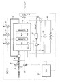
- FIG. 1 is a schematic structural view of a system for starting up a fuel cell stack at a subzero temperature
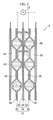
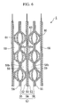
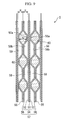
- FIG. 2 is a cross-sectional view for describing the laminated structure of a fuel cell stack 1. Note that the fuel cell stack of the present embodiment is designed to be mounted in a fuel cell vehicle.
- the fuel cell stack 1 is a solid polymer type of fuel cell.
- the fuel cell stack 1 is formed by sandwiching the two sides of a solid polymer electrolyte membrane 51, which is formed, for example, by a solid polymer ion exchange membrane or the like, between an anode electrode 52 and cathode electrode 53 so as to form a membrane electrode assembly 54.
- Separators 55 and 56 are then placed on both sides of the membrane electrode assembly 54 so as to form a single cell (i.e., a fuel cell unit) 57.
- a plurality of the single cells 57 are then stacked so as to form the fuel cell stack 1.
- the membrane electrode assembly is abbreviated to "MEA”
- the separators 55 and 56 are collectively referred to using the term "separator".
- the separators 55 and 56 are employed for the separators 55 and 56. More specifically, the separators 55 and 56 are manufactured by press forming metal plates, and are provided with a cross-sectional waveform in which first flattened portions 55a and 56a and second flattened portions 55b and 56b are placed alternatingly. The separators 55 and 56 are stacked such that the first flattened portion 55a of the separator 55 is placed against the anode electrode 52 of the membrane electrode assembly 54, and such that the second flattened portion 56a of the separator 56 is placed against the cathode electrode 53 of the membrane electrode assembly 54. The second flattened portions 55b and 56b of the separators 55 and 56 that have been placed adjacent to each other are placed against each other.
- Separators that are manufactured from metal can be made thinner than carbon separators, so that the size in the stacking direction of the fuel cell stack 1 can be shortened. In addition, they have the feature that they can be provided with a smaller heat capacity than carbon separators so that they can be warmed up more easily.
- a variety of metals that are suitable for press working can be used as the material for the metal separators.
- a stainless steel based material that has undergone a surface processing in order to improve the corrosion resistance and contact resistance thereof is used.
- a fuel cell stack 1 that has been formed by stacking a plurality of single cells 57 in this manner, spaces that are formed between the separators 55 and the anode electrodes 52 form fuel flow passages (i.e., reaction gas flow passages) 58 through which hydrogen gas (i.e., anode gas, reaction gas) is circulated. Spaces that are formed between the separators 56 and the cathode electrodes 53 form air flow passages (i.e., reaction gas flow passages) 59 through which air (i.e., cathode gas, reaction gas) is circulated. Spaces that are formed between two separators 55 and 56 placed adjacent to each other form coolant flow passages 60 through which coolant is circulated.
- the separators 55 and 56 have the function of separating anode gas from cathode gas, and also have the function of separating reaction gas flow passages from coolant flow passages.
- the fuel cell stack 1 can be said to be a solid polymer electrolyte fuel cell stack that is formed by stacking a plurality of layers of membrane electrode assemblies 54, which are provided with a solid polymer electrolyte membrane 51 and electrodes 52 and 53, with separators 55 and 56.
- the fuel cell stack 1 can be said to be a fuel cell stack that is formed by stacking a plurality of layers of membrane electrode assemblies 54, which are provided with a solid polymer electrolyte membrane 51 and electrodes 52 and 53, with metal separators 55 and 56 that have a cross-sectional waveform structure, and in which at least a portion of spaces that are enclosed by the separators and by separators that have been placed adjacent to these separators form coolant flow passages 60.
- the fuel cell stack 1 can be said to be a fuel cell stack that is formed by stacking a plurality of layers of membrane electrode assemblies 54, which are provided with a solid polymer electrolyte membrane 51 and electrodes 52 and 53, with separators 55 and 56 that are placed between adjacent membrane electrode assemblies 54.
- a voltage sensor 21 that measures output voltages from each of the single cells 57 is connected to the separators 55 and 56 of each single cell 57. Output signals from the voltage sensors 21 are input into an electronic control unit (referred to below as an ECU) 20. Note that, in FIG. 2, only one voltage sensor 21 is shown due to limitations of the drawings.
- a temperature sensor 22 that measures the temperature of the membrane electrode assembly 54 is provided in one single cell 57 that acts as a representative of the plurality of single cells 57 (see FIG. 1), and output signals from the temperature sensor 22 are input into the ECU 20.
- Air is compressed by a compressor 2 and is supplied to the air flow passages 59 (see FIG. 2) of the fuel cell stack 1. After oxygen in this air has served as an oxidizing agent for power generation, it is discharged as cathode off gas from the fuel cell stack 1, and is released to the atmosphere via a pressure control valve 4.
- the number of revolutions of the compressor 2 is controlled by the ECU 20 such that a mass of air that corresponds to the output required from the fuel cell stack 1 is supplied to the fuel cell stack 1.
- the aperture of the pressure control valve 4 is controlled by the ECU 20 such that the air supply pressure at which air is supplied to the fuel cell stack 1 is at a pressure value that corresponds to the operating state of the fuel cell stack 1.
- the air that is supplied to the fuel cell stack 1 is controlled such that the quantity of air that is supplied to the fuel cell stack 1 and also the air supply pressure are greater when the amount of power that the fuel cell stack 1 needs to generate is greater.
- the fuel supply control valve 5 may be formed, for example, by a pneumatic proportional pressure control valve.
- the pressure of air that is supplied from the compressor 2 is input via an air signal introduction passage 9 into the fuel supply control valve 5 as a signal pressure (i.e., a reference pressure), and the pressure of hydrogen gas at the outlet of the fuel supply control valve 5 is controlled so as to be within a predetermined pressure range that corresponds to this signal pressure.
- a signal pressure i.e., a reference pressure
- the pressure of the coolant that is used for cooling the fuel cell stack 1 is raised by a water pump 11 and the coolant is then supplied to a radiator 12.
- the coolant is cooled in the radiator 12 by the heat thereof being discharged to the outside, and the coolant is then supplied to be fuel cell stack 1 so as to cool the fuel cell stack 1 by capturing heat from the fuel cell stack 1 as it passes through the coolant flow passages 60 (see FIG. 2) inside the fuel cell stack 1. Coolant that has become heated as a result of this is then returned once more to the radiator 12 via the water pump 11 and is cooled.
- the ECU 20 controls the operation of the water pump 11 such that the amount of coolant that is circulated corresponds to the operating state of the fuel cell stack 1, and stops the water pump 11 when the coolant drops below a predetermined temperature.
- An electrical circuit 30 that is provided with an external load 31 is connected to the fuel cell stack 1.
- the external load 31 is variable.
- the electrical circuit 30 is provided with a current sensor 32 that is used to measure an output current (namely, the obtained current) from the fuel cell stack 1, and a voltage sensor 33 that is used to measure the terminal voltage (referred to below as stack voltage) of the fuel cell stack 1. Output signals from the current sensor 32 and voltage sensor 33 are input into the ECU 20.
- power that is obtained from the power generation of the fuel cell stack 1 can also be used to charge an auxiliary battery, and a structure is employed in which the various auxiliary devices that are required to operate the fuel cell stack 1, such as the compressor 2 and the water pump 11, are able to be supplied with power by the fuel cell stack 1 or by the auxiliary battery.
- the heat capacity in the power generating section of the fuel cell stack 1 is set to a predetermined capacity and, in addition, the power generating state of the fuel cell stack 1 is controlled so as to be a predetermined state. This will now be described in detail.
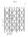
- the term "power generating section 50 of the fuel cell stack 1" refers essentially to a range in which power is generated, specifically, a three-dimensional volume in which the electrodes 52 and 53 can be superposed in a stacking direction. As is shown in FIG. 3, the fuel cell stack 1 is provided with a header section 70 surrounding the power generating section 50, which is the three-dimensional volume in which the electrodes 52 and 53 can be superposed in the stacking direction.
- a fuel distribution flow passage 71, an anode off gas collection flow passage 72, an air distribution flow passage 73, a cathode off gas collection flow passage 74, a coolant distribution flow passage 75, and a coolant collection flow passage 76 are each provided so as to penetrate each single cell 57 in the stacking direction, and the stacked state of the single cells 57 is maintained by stud bolts (not shown) that are mounted so as to penetrate the header section 70.
- the fuel distribution flow passage 71 and the anode off gas collection flow passage 72 are connected to the fuel flow passages 58 of each single cell 57
- the air distribution flow passage 73 and the cathode off gas collection flow passage 74 are connected to the air flow passages 59 of each single cell 57
- the coolant distribution flow passage 75 and the coolant collection flow passage 76 are connected to the coolant flow passages 60 of each single cell 57.
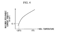
- the current density that can be generated stably (referred to below as the maximum obtainable current density) is determined in accordance with the cell internal temperature from the temperature characteristics of the electrolytic material that governs ion conduction, which is the material of the solid polymer electrolyte membrane 51.
- FIG 4 shows an example of the maximum obtainable current density characteristics. In the case of this example, under conditions, for example, in which the cell internal temperature is approximately -30°C, the maximum obtainable current density is approximately 0.1 A/cm 2 .
- the membrane electrode assembly 54 is provided with a porous diffusion layer used for diffusing reaction gas on outer sides of the electrodes 52 and 53.
- TABLE 1 is an example showing a relationship between the cell voltage and the size of the holes in the membrane electrode assembly when a cell internal temperature of 70°C and a maximum obtainable current density of approximately 0.5 A/cm 2 were set as normal operating conditions.
- single cells in which the size of the holes in the membrane electrode assembly 54 range from small to large are able to provide a sufficient cell voltage in practical use, however, single cells in which the size of the holes was extremely small were not practical as the cell voltage was too small.
- Cell voltage under normal operating conditions 70°C, 0.5 A/cm 2
- Size of holes in membrane electrode assembly Cell voltage (V) Small 0.71 Medium 0.71 Large 0.70 Extremely small 0.2
- TABLE 2 is an example showing a relationship in single cells that are provided with membrane electrode assemblies 54 having the same sized holes as those in TABLE 1 between the limited time for start-up and the size of the holes in the membrane electrode assembly 54, when the start-up commencement temperature was -30°C and a constant current was generated at the maximum obtainable current density at this start-up commencement temperature (0.1 A/cm2). Note that, because the cell voltage of the membrane electrode assembly 54 whose hole size was extremely small was too small under normal operating conditions to be of any practical use, it is omitted from TABLE 2.
- Single cell limited time for start-up Start-up commencement temperature: -30°C, Current density: 0.1 A/cm 2 ) Size of holes in membrane electrode assembly Limited time for start-up (sec) Small 180 Medium 340 Large 720
- a limited time for start-up that corresponds to the start-up commencement temperature is determined by the size of the holes in the membrane electrode assembly 54.
- the membrane electrode assembly 54 has a unique limited time for start-up that corresponds to the start-up commencement temperature.
- FIG. 5 shows the results in graph form when temperature characteristics of the membrane electrode assemblies 54 are determined by experiment when power is generated with the start-up commencement temperature at - 30°C, for a single cell 57 that is provided with membrane electrode assemblies 54 whose hole size is "Large” in TABLE 2 and whose heat capacity differs per unit area in the power generating section 50.
- CC mode in the drawing is an abbreviation of constant current generation mode
- CV mode is an abbreviation of constant voltage mode.
- the maximum heat capacity is specified by the start-up commencement temperature and the membrane electrode assembly that is used.
- TABLE 3 shows dimensional data of each section in each single cell 57 of the heat capacities A to E, and compares the thicknesses of the metal separators 55 and 56 (namely, the plate thicknesses), the thicknesses of the membrane electrode assemblies 54, and the depths of the coolant passages 60 (i.e., the "h” in FIG 2).
- the "none” that is recorded in the column for the depth of the coolant passage 60 in TABLE 3 shows that the coolant has been removed from the coolant passage 60 and has been replaced with air.
- Heat capacity J/k ⁇ cm 2
- Heat capacity A 0.092
- Heat capacity B 0.33
- Heat capacity C 0.55
- Heat capacity D 1.3
- Heat capacity E 1.94
- Separator thickness (mm) 0.1 0.15 0.45 1.3
- Membrane electrode assembly thickness (mm) 0.09 0.13 0.13 1.4 1.4
- a predetermined subzero temperature for example, -30°C
- the start-up commencement temperature becomes a design standard temperature and can be set as is appropriate.
- step S102 a maximum obtainable current density at the start-up commencement temperature is determined based on the maximum obtainable current density characteristics (see FIG 4) of the membrane electrode assembly 54 that is used, and the maximum obtainable current at this start-up commencement temperature is determined from the size of the power generating section 50 of the fuel cell stack 1.
- step S103 the limited time for start-up of the membrane electrode assembly 54 that is being used is calculated. Namely, for the single cell that is provided with the membrane electrode assembly 54 being used, the limited time for start-up at the time when a constant current is generated at the maximum obtainable current density at the start-up commencement temperature is calculated from the start-up commencement temperature set in step S101 by referring to experimental data that has been collected in advance.
- step S104 based on the start-up commencement temperature set in step S101 and on the limited time for start-up calculated in step S103, the maximum heat capacity per unit area per single cell in the power generating section 50 of the fuel cell stack 1 is calculated. From this, the maximum heat capacity in the power generating section 50 of the fuel cell stack 1 is calculated.
- the term "per single cell” means dividing the heat capacity of a three-dimensional portion obtained by stacking electrode portions in the stacking direction (namely, of the power generating section 50) by the number of layers of the membrane electrode composite body 54. The heat capacity per single cell that is thereby obtained is then further divided by the surface area of the electrode portion (i.e., the power generating section 50) so as to give the "heat capacity per unit area per single cell".
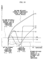
- an amount of heat that is obtained by subtracting the amount of discharge heat from the amount of generated heat is calculated as the amount of heat that is essentially used for the increase in temperature of the power generating section 50.
- the amount of heat generated in the power generating section 50 can be calculated as the amount of heat that is generated from the start-up commencement temperature until the temperature reaches 0°C when constant current is generated at the maximum obtainable current density that corresponds to this start-up commencement temperature, and the amount of discharge heat can be calculated by experiment (or by experience). Note that when a coolant is circulating during start-up, the amount of heat that is captured by coolant in the coolant flow passages is included in the amount of discharge heat.
- step S105 detailed portions of the single cells 57 that use the metal separators 55 and 56 are designed such that the maximum heat capacity per unit area per single cell is less than what was calculated in step S104.
- the quantity of coolant that is held in the single cells 57 has a considerable effect on the heat capacity of the power generating section 50, if it is assumed that the fuel cell stack 1 is started while coolant is being held in the coolant flow passages 60, it is extremely effective for reducing the heat capacity per unit area per single cell if the single cells 57 are designed such that the quantity of coolant that is held therein is reduced.
- the heat capacity of the fuel cell stack 1 can be set to a heat capacity such that, in a case in which the temperature of the fuel cell stack 1 is raised by self-generated heat when power is generated while the maximum obtainable current at a predetermined start-up commencement temperature is maintained, the temperature of the membrane electrode assembly 54 reaches 0°C or more before the membrane electrode assembly 54 becomes unable to generate power.
- the design conditions include completing warm-up inside three minutes even when the start-up commencement temperature is -30°C, then it is desirable that the heat capacity per unit area per single cell is between 0.04 and 0.33 J/K ⁇ cm 2 .
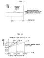
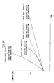
- FIG 10 shows temperature increase characteristics of a single cell 57 in which the limited time for start-up is, for example, three minutes when constant current power generation is conducted at the maximum obtainable current density using a membrane electrode assembly 54 in which the start-up commencement temperature is set to -30°C and the maximum obtainable current density is 0.1 A/cm 2 . If it is accepted that the maximum heat capacity per unit area in the power generating section 50 of the single cells 57 is 0.33 J/K ⁇ cm 2 , then in the case of a single cell 57 having a smaller heat capacity (i.e., 0.29 J/K ⁇ cm 2 ) than the maximum heat capacity, the rate of temperature increase is faster than that of the maximum heat capacity.
- the rate of temperature increase of the power generating section 50 is slower than when the constant current generation was conducted at the maximum obtainable current density (namely, at the time of the temperature characteristics shown in FIG. 10).
- the quantity of water that is generated by the power generation is less if the obtained current density is reduced, the limited time for start-up is extended beyond when the constant current generation was conducted at the maximum obtainable current density (namely, at the time of the temperature characteristics shown in FIG. 10).
- the rate of temperature increase of the power generating section 50 is faster than when the constant current generation was conducted at the maximum obtainable current density (namely, at the time of the temperature characteristics shown in FIG. 10).
- the quantity of water that is generated by the power generation is greater if the obtained current density is increased, the limited time for start-up becomes shorter than when the constant current generation was conducted at the maximum obtainable current density (namely, at the time of the temperature characteristics shown in FIG. 10).
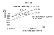
- the obtained current density is set as the maximum obtainable current density
- the limited time for start-up is the same as in the case of the temperature characteristics shown in FIG. 10.
- the rate of temperature increase of the power generating section 50 is also the same as in the case of the temperature characteristics shown in FIG 10.
- the temperature characteristics shown in FIG 15 move exactly in parallel on the high temperature side with the temperature characteristics shown in FIG. 10.
- the rate of temperature increase of the power generating section 50 is slower than when the constant current generation was conducted at the maximum obtainable current density (namely, at the time of the temperature characteristics shown in FIG. 15).
- the quantity of water that is generated by the power generation is less if the obtained current density is reduced, the limited time for start-up is extended beyond when the constant current generation was conducted at the maximum obtainable current density (namely, at the time of the temperature characteristics shown in FIG. 15).
- the rate of temperature increase of the power generating section 50 is faster than when the constant current generation was conducted at the maximum obtainable current density (namely, at the time of the temperature characteristics shown in FIG. 15).
- the quantity of water that is generated by the power generation is greater if the obtained current density is increased, the limited time for start-up becomes shorter than when the constant current generation was conducted at the maximum obtainable current density (namely, at the time of the temperature characteristics shown in FIG. 15).
- the heat capacity per unit area in the heat generating section 50 of the single cells 57 is set to the maximum heat capacity or less, then provided that the start-up commencement temperature does not go below the start-up commencement temperature that was set in advance when the heat capacity was determined, even if the obtained current density is increased or decreased relative to the maximum obtainable current density, it is still possible to raise the temperature of the power generating section 50 of a membrane electrode assembly 54 in the single cells 57 to 0°C or more within the limited time for start-up.
- the minimum current density necessary to compensate for the discharged heat should be set as the lower limit value for the obtained current density, and control must be performed such that the obtained current density is held at or above this lower limit value.
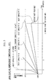
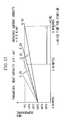
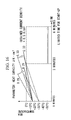
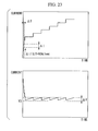
- FIG. 18 shows specific examples of obtained current control when the fuel cell stack 1 is started up at a subzero temperature.
- the obtained current from the fuel cell stack 1 is on the vertical axis, and the obtained current density is formed by a value obtained by dividing the obtained current by the surface area of the power generating section 50.
- the single dot chain line is a line connecting the maximum obtainable currents at each temperature in the temperature rising process, and the obtained current does not exceed this regardless of the mode of operation of the fuel cell stack 1.
- the double dot chain line in FIG. 18 shows the average of the minimum current value necessary (i.e., the minimum necessary current) to complement the discharged heat, while the broken line in FIG. 18 shows the maximum obtainable current that corresponds to the maximum obtainable current density at the start-up commencement temperature (for example, -30°C) that was standard when the maximum heat capacity of the single cells 57 was being set.
- reference symbols (a) to (f) show examples of the control of a suitable obtained current for subzero start-up of the fuel cell stack 1.
- the examples of obtained current control indicated by reference symbols (a) to (c) are all cases in which the start-up of the fuel cell stack 1 is commenced from the design standard start-up commencement temperature (i.e., -30°C), and show examples in which a control method is employed that maintains the obtained current at a predetermined current that is equal to or greater than the minimum necessary current. This control method will be referred to below as constant current generation.
- the example of obtained current control indicated by reference symbol (d) commences start-up of the fuel cell stack 1 with a temperature higher (for example, -15°C) than the design standard start-up temperature (i.e., - 30°C) set as the start-up commencement temperature, and shows an example in which a control method is employed that conducts constant current generation with the obtained current set to the minimum necessary current or greater.
- the example of obtained current control indicated by reference symbol (e) is an example in which control is performed such that when the obtained current temporarily drops for only a brief period below the minimum necessary current, it is immediately restored to the minimum necessary current or greater.
- the temperature of the membrane electrode assemblies 54 can be restored by rapidly increasing the quantity of heat that is generated after the obtained current has been restored to the minimum necessary current or greater, and it is possible to raise the temperature of the membrane electrode assemblies 54 to 0°C or greater within the limited time for start-up.
- the example of obtained current control indicated by reference symbol (f) is an example in which a control method is employed that maintains the output voltage of the fuel cell stack 1 at a predetermined voltage value. This control method is referred to below as constant voltage generation. Note that the example of obtained current control indicated by reference symbol (f) is an example in which control is conducted such that the obtained current has a value that is close to the maximum obtainable current at each temperature in the temperature rising process.
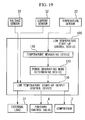
- the fuel cell stack 1 is provided with a low temperature start-up control device 100.
- the low temperature start-up control device 100 is provided with a temperature measuring device 110, a power generating mode determining device 120, and a low temperature start-up output control device 130.
- the temperature measuring device 110 measures the internal temperature inside the fuel cell stack 1 (i.e., the temperature of the membrane electrode assemblies 54) based on output signals from a temperature sensor 22.
- the power generating mode determining device 120 determines whether start-up should be carried out in normal power generating mode or in low temperature start-up power generating mode based on the internal temperature of the fuel cell stack 1 that has been measured.
- the low temperature start-up output control device 130 controls the output from the fuel cell stack 1 such that the output current of the fuel cell stack 1 is equal to or greater than the minimum necessary current required to compensate for the discharged heat using one of the control methods described below in detail, while monitoring output current of the fuel cell stack 1 that has been input from a current sensor 32 and stack voltage that has been input from a voltage sensor 33.
- the output control of the fuel cell stack 1 is controlled by controlling the supply of reaction gas (i.e., hydrogen gas and air) by controlling at least one of the aperture of a pressure control valve 4 and the operation of the compressor 2, and by controlling the load amount of an external load 31.
- the low temperature start-up control device 100 is a control device that raises the temperature of the fuel cell stack 1 from a subzero start-up commencement temperature, while controlling at least one of the flow quantity and pressure of reaction gas that is introduced into the fuel cell stack 1, and at least one of the output current and output voltage of the fuel cell stack 1.
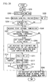
- the flowchart shown in FIG 20 shows a start-up control routine when the fuel cell stack 1 is started up by the aforementioned constant current power generation at a subzero temperature. This start-up control routine is executed by the ECU 20.
- reaction gas is supplied to the fuel cell stack 1 (step S202). Namely, the compressor 2 is operated and the pressure control valve 4 and the fuel supply control valve 5 are opened. In addition, air is supplied to the air flow passages 59 and hydrogen gas is supplied to the fuel flow passages 58 of each single cell 57 of the fuel cell stack 1.
- the cell voltage of each single cell 57 is measured by the respective voltage sensors 21 (step S203), and a determination is made as to whether or not the lowest cell voltage from among the measured cell voltages is larger than a first threshold voltage V1 that has been set in advance (step S204).
- the first threshold voltage V1 is set to the open circuit voltage value at which it is determined that the reaction gas has permeated to the electrodes 52 and 53 of the membrane electrode assemblies 54 in each single cell 57.
- step S204 If the result of the determination in step S204 is NO (i.e., the lowest cell voltage ⁇ V1), then because the reaction gas has not yet permeated to the electrodes 52 and 53 of the membrane electrode assemblies 54 in each single cell 57, after a predetermined time ⁇ T has been maintained (step S205), the routine returns to step S203. Namely, the processing of steps S203 to S205 is repeatedly executed until the lowest cell voltage exceeds the first threshold voltage V1.
- predetermined time ⁇ T in step S205 and the predetermined time ⁇ T in step S211 are both set to as short a time as possible within a controllable range.
- step S204 If the result of the determination in step S204 is YES (i.e., the lowest cell voltage > V1), the routine proceeds to step S206, and the internal temperature of the fuel cell stack 1 is measured.
- the internal temperature of the fuel cell stack 1 is the temperature of the membrane electrode assemblies 54 in the single cell 57 that is measured by the temperature sensor 22.
- This reference temperature is set to a temperature at which the fuel cell stack 1 is able to generate power consistently at a reaction gas flow rate and pressure that are set based on a normal mode map (namely, a warm-up completion temperature).
- step S207 If the result of the determination in step S207 is NO (i.e., the stack internal temperature ⁇ reference temperature), then because start-up is possible in normal power generating mode, the reaction gas flow rate and pressure are set in accordance with the required power based on normal mode map (step S208), and at least one of the number of revolutions of the compressor 2 and the aperture of the pressure control valve 4 are controlled such that the set reaction gas flow rate and pressure are achieved. The processing of the routine is then temporarily ended.
- NO i.e., the stack internal temperature ⁇ reference temperature
- step S207 If, however, the result of the determination in step S207 is YES, (i.e., the stack internal temperature ⁇ reference temperature), then because it is necessary to perform the start-up in low temperature start-up power generating mode, the output current of the fuel cell stack 1 is set to a fixed value (step S209), and thereafter the reaction gas flow rate and pressure are set based on a low temperature mode map (step S210), and at least one of the number of revolutions of the compressor 2 and the aperture of the pressure control valve 4 are controlled such that the set reaction gas flow rate and pressure are achieved.
- the fixed current value set in step S209 is equal to or more than the minimum required current, and may be set always to a fixed value regardless of the start-up commencement temperature.
- the fixed current value may be altered in accordance with the start-up commencement temperature. If the fixed current value is altered in accordance with the start-up commencement temperature, then control such as that shown by (d) in FIG. 18 becomes possible.
- control such as that shown by (d) in FIG. 18 becomes possible.
- the reaction gas flow rate and pressure are set greater than in the normal mode map when a comparison is made for the same power requirements.
- the cell voltage of each single cell 57 is measured by the respective voltage sensors 21 (step S212), and a determination is made as to whether or not the lowest cell voltage from among the measured cell voltages is less than a second threshold voltage V2 that has been set in advance (step S213).
- the second threshold voltage V2 is set to a voltage threshold below which damage will occur in the membrane electrode assemblies 54 (i.e., to a cell voltage lower limit value).
- step S213 If the result of the determination in step S213 is YES (i.e., the lowest cell voltage ⁇ V2), the output current I is reduced by the amount ⁇ I (step S214) and the routine returns to step S211.
- step S213 If the result of the determination in step S213 is NO (i.e., the lowest cell voltage ⁇ V2), then the routine returns to step S206 without either decreasing or increasing the output current I. Namely, the processing of step S206, step S207, and steps S209 to S214 is repeated until the internal temperature of the fuel cell stack 1 equals or exceeds the reference temperature.
- the fuel cell stack 1 can be operated with the output current I from the fuel cell stack 1 made substantially uniform with the current value set in step S209.
- the output current I is set equal to or more than the minimum required current, it is possible to compensate for the discharged heat from the fuel cell stack 1, it is also possible to reliably raise the temperature of the power generating section 50 to 0°C or greater within the limited time for start-up using only the self generated heat that is created by the power generation of the fuel cell stack 1, and it is also possible to reliably transit to normal power generating mode while maintaining power generation. Accordingly, it is possible to prevent the fuel cell stack 1 from degenerating midway through start-up into a state in which is unable to generate power due to freezing of generated water, and power generation by the fuel cell stack can be continuously maintained.
- the temperature measuring device 110 is formed by the temperature sensor 22 and the ECU 20 executing the processing of step S206
- the power generating mode determining device 120 is achieved by the ECU 20 executing the processing of step S207
- the low temperature start-up output control device 130 is achieved by the ECU 20 executing the processing of steps S209 to S211.
- the temperature measuring device 110, the power generating mode determining device 120, and the low temperature start-up output control device 130 constitute the low temperature start-up control device 100 that raises the temperature of the fuel cell stack 1 from a subzero start-up commencement temperature while controlling at least one of the flow rate and pressure of reaction gas that is introduced into the fuel cell stack 1 and controlling output current of the fuel cell stack 1.
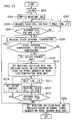
- the flowchart shown in FIG. 21 shows a start-up control routine when output current of the fuel cell stack 1 is controlled using suitable current values that are set between the minimum required current and the maximum obtainable current at a subzero start-up.
- This start-up control routine is executed by the ECU 20.
- the flowchart shown in FIG. 21 is basically the same as the flowchart shown in FIG. 20, and only varies in step S219 which corresponds to step S209 in the flowchart in FIG. 20.
- step S219 which corresponds to step S209 in the flowchart in FIG. 20.
- the same step numbers are given to processing in control example 2 that is the same as that in control example 1, and a description thereof is omitted, only step S219 is described.
- step S219 the output current of the fuel cell stack 1 is set while referring to an output current map (not shown) that uses, for example, the internal temperature of the fuel cell stack 1 as a parameter.
- the output current map is created in advance based on experiment data or the like.
- the output current map may be set such that the output current increases in steps. Alternatively, depending on how the map is made, the output current can be made to change at a value that is close to the maximum obtainable current at a temperature during temperature increase process.
- control example 2 in a subzero start-up, the fuel cell stack 1 can be operated while the output current is changed in accordance with an output current map that has been previously created, and if the output current map is set such that the output current increases by steps, it is possible to raise the temperature of the power generating section 50 more rapidly than by the constant current power generation of control example 1.
- the temperature measuring device 110 is formed as a result of the temperature sensor 22 and the ECU 20 executing the processing of step S206, the power generating mode determining device 120 is achieved by the ECU 20 executing the processing of step S207, and the low temperature start-up output control device 130 is achieved by the ECU 20 executing the processing of steps S219, S210 and S211.
- the temperature measuring device 110, the power generating mode determining device 120, and the low temperature start-up output control device 130 constitute the low temperature start-up control device 100 that raises the temperature of the fuel cell stack 1 from a subzero start-up commencement temperature while controlling at least one of the flow rate and pressure of reaction gas that is introduced into the fuel cell stack 1 and controlling output current of the fuel cell stack 1.
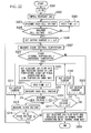
- the flowchart shown in FIG. 22 shows a start-up control routine when the fuel cell stack 1 is started up by the aforementioned constant voltage power generation at a subzero temperature. This start-up control routine is executed by the ECU 20.
- reaction gas is supplied to the fuel cell stack 1 (step S302). Namely, the compressor 2 is operated and the pressure control valve 4 and the fuel supply control valve 5 are opened. In addition, air is supplied to the air flow passages 59 and hydrogen gas is supplied to the fuel flow passages 58 of each single cell 57 of the fuel cell stack 1.
- the cell voltage of each single cell 57 is measured by the respective voltage sensors 21 (step S303), and a determination is made as to whether or not the lowest cell voltage from among the measured cell voltages is larger than a first threshold voltage V1 that has been set in advance (step S304).
- the first threshold voltage V1 is set to the open circuit voltage value at which it is determined that the reaction gas has permeated to the electrodes 52 and 53 of the membrane electrode assemblies 54 in each single cell 57.
- step S304 If the result of the determination in step S304 is NO (i.e., the lowest cell voltage ⁇ V1), then because the reaction gas has not yet permeated to the electrodes 52 and 53 of the membrane electrode assemblies 54 in each single cell 57, after a predetermined time ⁇ T has been maintained (step S305), the routine returns to step S303. Namely, the processing of steps S303 to S305 is repeatedly executed until the lowest cell voltage exceeds the first threshold voltage V1.
- predetermined time ⁇ T in step S305 and the predetermined time ⁇ T in step S311 are both set to as short a time as possible within a controllable range.
- step S304 If the result of the determination in step S304 is YES (i.e., the lowest cell voltage is > V1), ⁇ I is set for the output current I of the fuel cell stack 1 (step S306), and the internal temperature of the fuel cell stack 1 is measured (step S307).
- the internal temperature of the fuel cell stack 1 is the temperature of the membrane electrode assemblies 54 in the single cell 57 that is measured by the temperature sensor 22.
- This reference temperature is set to a temperature at which the fuel cell stack 1 is able to generate power consistently at a reaction gas flow rate and pressure that are set based on a normal mode map (namely, a warm-up completion temperature).
- step S308 If the result of the determination in step S308 is NO (i.e., the stack internal temperature ⁇ reference temperature), then because start-up is possible in normal power generating mode, the reaction gas flow rate and pressure are set in accordance with the required power based on normal mode map (step S309), and at least one of the number of revolutions of the compressor 2 and the aperture of the pressure control valve 4 are controlled such that the set reaction gas flow rate and pressure are achieved. The processing of the routine is then temporarily ended.
- NO i.e., the stack internal temperature ⁇ reference temperature
- step S308 If, however, the result of the determination in step S308 is YES, (i.e., the stack internal temperature ⁇ reference temperature), then because it is necessary to perform the start-up in low temperature start-up power generating mode, the reaction gas flow rate and pressure are set based on a low temperature mode map (step S310), and at least one of the number of revolutions of the compressor 2 and the aperture of the pressure control valve 4 are controlled such that the set reaction gas flow rate and pressure are achieved. In the low temperature mode map, the reaction gas flow rate and pressure are set greater than in the normal mode map when a comparison is made for the same power requirements.
- step S311 the cell voltage of each single cell 57 is measured by the respective voltage sensors 21 (step S312), and a determination is made as to whether or not the lowest cell voltage from among the measured cell voltages is less than a second threshold voltage V2 that has been set in advance (step S313).
- the second threshold voltage V2 is set to a voltage threshold below which damage will occur in the membrane electrode assemblies 54 (i.e., to a cell voltage lower limit value).
- step S313 If the result of the determination in step S313 is YES (i.e., the lowest cell voltage ⁇ V2), the output current I is reduced by the amount ⁇ I (step 314) and the routine returns to step S310.
- step S313 If the result of the determination in step S313 is NO (i.e., the lowest cell voltage ⁇ V2), then the current setting of the output current I is maintained and the stack voltage of the fuel cell stack 1 is measured by the voltage sensor 33 (step S315). A determination is then made as to whether or not the measured stack voltage is within a range that is greater than a predetermined voltage V3 and less than "V3+ ⁇ V".
- V3 is a predetermined voltage value that is set in advance, and, when the lower limit value is the minimum voltage necessary to operate the fuel cell system, is set to a value that is larger than this lower limit value.
- ⁇ V is set, based on the current and voltage characteristics of the fuel cell stack 1, as the amount of change in the voltage when the current changes by ⁇ I.
- step S316 the determination in step S316 is NO, and the routine proceeds to step S317.
- step S318 is repeatedly executed until the stack voltage drops below "V3+ ⁇ V", so that control of the increase of the output current I is continuously conducted.
- step S316 is YES.
- step S316 When the result of the determination in step S316 is YES (i.e., V3 ⁇ stack voltage ⁇ V3 + ⁇ V), the changes in the stack voltage are within a permissible range, and the stack voltage can be regarded as substantially a constant voltage. Therefore, the routine returns to step S307 without the output current being changed.
- step S316 When the stack voltage drops below the predetermined voltage V3, the determination in step S316 is NO, and, in addition, the determination in step S317 is NO.
- the fuel cell stack 1 can be operated with the output voltage from the fuel cell stack 1 made substantially uniform with the predetermined voltage V3.
- the temperature measuring device 110 is formed by the temperature sensor 22 and the ECU 20 executing the processing of step S307
- the power generating mode determining device 120 is achieved by the ECU 20 executing the processing of step S308
- the low temperature start-up output control device 130 is achieved by the ECU 20 executing the processing of steps S306, S310, S311, S315, S316, and S318.
- the temperature measuring device 110, the power generating mode determining device 120, and the low temperature start-up output control device 130 constitute the low temperature start-up control device 100 that raises the temperature of the fuel cell stack 1 from a subzero start-up commencement temperature while controlling at least one of the flow rate and pressure of reaction gas that is introduced into the fuel cell stack 1 and while controlling output voltage of the fuel cell stack 1.
- FIG. 24 gives the results of an experiment and shows a comparison between changes in the internal temperature of the fuel cell stack 1 in subzero temperature start-ups using the above described control example 1 (i.e., constant current power generation) and control example 3 (i.e., constant voltage power generation) when the start-up commencement temperatures were identical.
- the experiment was conducted using the respective control examples for a case in which the heat capacity of the power generating section of the fuel cell stack 1 was large and for a case in which it was small.
- the heat capacity of the power generating section 50 is made small and that the operation of the fuel cell stack 1 is controlled using constant voltage power generation.
- the heat capacity per unit area of the power generating section 50 of the single cells 57 during start-up is set to less than the maximum heat capacity, and, in this state, by performing the same controls as in each of the above described control examples 1 to 3, it becomes possible to control the output from the fuel cell stack 1 such that the output current of the fuel cell stack 1 becomes equal to or greater than the minimum necessary current that is required to compensate for the discharge heat quantity, and it becomes possible to start up the fuel cell stack 1.
- the heat capacity of the fuel cell stack 1 can be rapidly decreased.
- the fuel cell stack 1 is placed in a state in which there is no coolant in the coolant flow passages 60 during start-up, if the heat capacity per unit area of the power generating section 50 of the single cells 57, in a state in which no coolant is held in the coolant flow passages 60, is less than the maximum heat capacity, then because, in a state in which coolant is held in the coolant flow passages 60, the heat capacity per unit area of the power generating section 50 of the single cells 57 is able to exceed the maximum heat capacity, the degree of freedom when designing the single cells 57 is increased.
- the timing at which the coolant is removed from the coolant flow passages 60 is not restricted to when the fuel cell system is stopped, and it is also possible to form a fuel cell system in which the external temperature can be measured, and in which the coolant can be automatically removed at the point in time when the measured external temperature is on the verge of the coolant freezing temperature. Moreover, the timing at which the coolant is reintroduced into the coolant flow passages 60 can be determined in accordance with the internal temperature inside the fuel cell stack 1 and with the rate of temperature increase.
- the cross sectional waveform of the separators is not limited to the waveforms in the embodiments described above, and a curved waveform may be used or a rectangular cross-sectional configuration whose bends are substantially right angles may be used.
- the present invention can be used in fuel cells that are mounted in moving bodies such as motor vehicles, or in stationary fuel cells.
- a method of starting up at a subzero temperature a solid polymer electrolyte fuel cell stack that is formed by stacking a plurality of layers of separators and membrane electrode assemblies having a solid polymer electrolyte membrane and electrodes.
- the method includes a step of using a solid polymer electrolyte fuel cell stack in which the separators are made from metal and have a cross-sectional waveform structure, and a space that is formed between at least a portion of the separators and separators that are placed adjacent to this portion of the separators is used as a coolant flow passage.
Landscapes
- Life Sciences & Earth Sciences (AREA)
- Engineering & Computer Science (AREA)
- Manufacturing & Machinery (AREA)
- Sustainable Development (AREA)
- Sustainable Energy (AREA)
- Chemical & Material Sciences (AREA)
- Chemical Kinetics & Catalysis (AREA)
- Electrochemistry (AREA)
- General Chemical & Material Sciences (AREA)
- Fuel Cell (AREA)
Priority Applications (1)
| Application Number | Priority Date | Filing Date | Title |
|---|---|---|---|
| EP11186712.3A EP2413412B1 (de) | 2003-09-08 | 2004-09-06 | Verfahren und System zum Starten eines Brennstoffzellstapels bei Minustemperaturen und Verfahren zum Entwurf eines Brennstoffzellstapels |
Applications Claiming Priority (2)
| Application Number | Priority Date | Filing Date | Title |
|---|---|---|---|
| JP2003315725A JP5000073B2 (ja) | 2003-09-08 | 2003-09-08 | 燃料電池スタックの氷点下起動方法、燃料電池スタックの氷点下起動システム、および燃料電池スタックの設計方法 |
| JP2003315725 | 2003-09-08 |
Related Child Applications (1)
| Application Number | Title | Priority Date | Filing Date |
|---|---|---|---|
| EP11186712.3 Division-Into | 2011-10-26 |
Publications (3)
| Publication Number | Publication Date |
|---|---|
| EP1513209A2 true EP1513209A2 (de) | 2005-03-09 |
| EP1513209A3 EP1513209A3 (de) | 2009-12-09 |
| EP1513209B1 EP1513209B1 (de) | 2012-03-07 |
Family
ID=34131939
Family Applications (2)
| Application Number | Title | Priority Date | Filing Date |
|---|---|---|---|
| EP11186712.3A Expired - Lifetime EP2413412B1 (de) | 2003-09-08 | 2004-09-06 | Verfahren und System zum Starten eines Brennstoffzellstapels bei Minustemperaturen und Verfahren zum Entwurf eines Brennstoffzellstapels |
| EP04021132A Expired - Lifetime EP1513209B1 (de) | 2003-09-08 | 2004-09-06 | Verfahren Verfahren zum Entwurf eines Brennstoffzellenstapels |
Family Applications Before (1)
| Application Number | Title | Priority Date | Filing Date |
|---|---|---|---|
| EP11186712.3A Expired - Lifetime EP2413412B1 (de) | 2003-09-08 | 2004-09-06 | Verfahren und System zum Starten eines Brennstoffzellstapels bei Minustemperaturen und Verfahren zum Entwurf eines Brennstoffzellstapels |
Country Status (4)
| Country | Link |
|---|---|
| US (1) | US7572529B2 (de) |
| EP (2) | EP2413412B1 (de) |
| JP (1) | JP5000073B2 (de) |
| CA (2) | CA2664716C (de) |
Cited By (6)
| Publication number | Priority date | Publication date | Assignee | Title |
|---|---|---|---|---|
| US7749632B2 (en) | 2006-07-27 | 2010-07-06 | Gm Global Technology Operations, Inc. | Flow shifting coolant during freeze start-up to promote stack durability and fast start-up |
| US7867642B2 (en) | 2006-10-27 | 2011-01-11 | GM Global Technology Operations LLC | Fuel cell start optimization |
| US7883810B2 (en) | 2006-11-09 | 2011-02-08 | GM Global Technology Operations LLC | Slow purge for improved water removal, freeze durability, purge energy efficiency and voltage degradation due to shutdown/startup cycling |
| EP2357700A1 (de) * | 2010-01-14 | 2011-08-17 | Honda Motor Co., Ltd. | Brennstoffzellenvorrichtung |
| US8415061B2 (en) | 2009-11-26 | 2013-04-09 | Toyota Jidosha Kabushiki Kaisha | Fuel cell system and control method of same |
| EP2355219A4 (de) * | 2008-11-04 | 2015-04-08 | Nissan Motor | Steuervorrichtung und steuerverfahren für die erzeugung einer brennstoffzelle |
Families Citing this family (67)
| Publication number | Priority date | Publication date | Assignee | Title |
|---|---|---|---|---|
| US20050271908A1 (en) * | 2004-06-02 | 2005-12-08 | Bruce Lin | Cooling subsystem for an electrochemical fuel cell system |
| JP4855743B2 (ja) * | 2004-09-30 | 2012-01-18 | 株式会社日立製作所 | 燃料電池を用いた電源装置およびその制御方法 |
| JP4752342B2 (ja) * | 2005-06-15 | 2011-08-17 | 株式会社デンソー | 燃料電池システム |
| JP4772391B2 (ja) * | 2005-06-17 | 2011-09-14 | 本田技研工業株式会社 | 燃料電池システムおよび燃料電池システムの制御方法 |
| JP4945938B2 (ja) * | 2005-07-04 | 2012-06-06 | 日産自動車株式会社 | 燃料電池システム |
| JP4328324B2 (ja) | 2005-10-17 | 2009-09-09 | 本田技研工業株式会社 | 燃料電池システム |
| KR101023618B1 (ko) * | 2005-12-27 | 2011-03-21 | 닛산 지도우샤 가부시키가이샤 | 연료 전지 시스템 |
| JP5103739B2 (ja) * | 2006-01-16 | 2012-12-19 | 日産自動車株式会社 | 燃料電池システム及び燃料電池車両 |
| JP4976695B2 (ja) * | 2006-01-16 | 2012-07-18 | 本田技研工業株式会社 | 燃料電池システム |
| JP5151057B2 (ja) * | 2006-04-07 | 2013-02-27 | トヨタ自動車株式会社 | 燃料電池運転システム及び燃料電池運転システムにおける弁の協調制御方法 |
| US20080050629A1 (en) * | 2006-08-25 | 2008-02-28 | Bruce Lin | Apparatus and method for managing a flow of cooling media in a fuel cell stack |
| US8835065B2 (en) * | 2006-09-29 | 2014-09-16 | GM Global Technology Operations LLC | Fuel cell startup method for fast freeze startup |
| JP5065655B2 (ja) * | 2006-11-15 | 2012-11-07 | 本田技研工業株式会社 | 燃料電池システム |
| JP2008147139A (ja) * | 2006-12-13 | 2008-06-26 | Toyota Motor Corp | 燃料電池システム |
| JP5060118B2 (ja) * | 2006-12-18 | 2012-10-31 | 本田技研工業株式会社 | 燃料電池システム |
| JP5200414B2 (ja) | 2007-04-26 | 2013-06-05 | トヨタ自動車株式会社 | 燃料電池システム |
| JP5261987B2 (ja) * | 2007-05-31 | 2013-08-14 | 日産自動車株式会社 | 燃料電池システム |
| JP5318382B2 (ja) * | 2007-08-07 | 2013-10-16 | 本田技研工業株式会社 | 燃料電池スタック |
| JP2007317680A (ja) * | 2007-09-03 | 2007-12-06 | Honda Motor Co Ltd | 燃料電池スタックの氷点下起動方法 |
| JP5235450B2 (ja) * | 2008-02-27 | 2013-07-10 | キヤノン株式会社 | 燃料電池の凍結検知方法 |
| US7897692B2 (en) * | 2008-05-09 | 2011-03-01 | Gm Global Technology Operations, Inc. | Sulfonated perfluorocyclobutane block copolymers and proton conductive polymer membranes |
| US8008404B2 (en) * | 2008-05-09 | 2011-08-30 | GM Global Technology Operations LLC | Composite membrane |
| US7897693B2 (en) * | 2008-05-09 | 2011-03-01 | Gm Global Technology Operations, Inc. | Proton conductive polymer electrolytes and fuel cells |
| US7897691B2 (en) * | 2008-05-09 | 2011-03-01 | Gm Global Technology Operations, Inc. | Proton exchange membranes for fuel cell applications |
| US8030405B2 (en) * | 2008-05-09 | 2011-10-04 | GM Global Technology Operations LLC | Blended PEM's with elastomers for improved mechanical durability |
| US7985805B2 (en) * | 2008-05-09 | 2011-07-26 | GM Global Technology Operations LLC | Polyelectrolyte membranes comprised of blends of PFSA and sulfonated PFCB polymers |
| US7888433B2 (en) * | 2008-05-09 | 2011-02-15 | Gm Global Technology Operations, Inc. | Sulfonated-polyperfluoro-cyclobutane-polyphenylene polymers for PEM fuel cell applications |
| JP5239577B2 (ja) * | 2008-07-22 | 2013-07-17 | トヨタ自動車株式会社 | 燃料電池システムおよび燃料電池の起動方法 |
| US8003732B2 (en) * | 2008-08-25 | 2011-08-23 | GM Global Technology Operations LLC | Gradient reinforced proton exchange membrane |
| US7976730B2 (en) * | 2008-08-25 | 2011-07-12 | GM Global Technology Operations LLC | Blends of low equivalent molecular weight PFSA ionomers with Kynar 2751 |
| JP5314364B2 (ja) * | 2008-09-04 | 2013-10-16 | 三菱重工業株式会社 | 燃料電池発電システムおよび燃料電池の出力制御方法 |
| JP5312907B2 (ja) * | 2008-10-31 | 2013-10-09 | 本田技研工業株式会社 | 燃料電池システム |
| US20110045381A1 (en) * | 2009-08-18 | 2011-02-24 | Gm Global Technology Operations, Inc. | Hydrocarbon PEM Membranes with Perfluorosulfonic Acid Groups for Automotive Fuel Cells |
| US8852823B2 (en) * | 2009-08-26 | 2014-10-07 | GM Global Technology Operations LLC | Sodium stannate additive to improve the durability of PEMS for H2/air fuel cells |
| US8053530B2 (en) * | 2009-08-26 | 2011-11-08 | GM Global Technology Operations LLC | Polyelectrolyte membranes made of poly(perfluorocyclobutanes) with pendant perfluorosulfonic acid groups and blends with poly(vinylidene fluoride) |
| US8354201B2 (en) * | 2009-08-28 | 2013-01-15 | GM Global Technology Operations LLC | Fuel cell with spatially non-homogeneous ionic membrane |
| US7972732B2 (en) * | 2009-08-28 | 2011-07-05 | GM Global Technology Operations LLC | Perfluorocyclobutane based water vapor transfer membranes with side chain perfluorosulfonic acid moieties |
| US20110053009A1 (en) * | 2009-08-28 | 2011-03-03 | Gm Global Technology Operations, Inc. | Customized water vapor transfer membrane layered structure |
| US20110053008A1 (en) * | 2009-08-28 | 2011-03-03 | Gm Global Technology Operations, Inc. | Water vapor transfer membrane and paper integrated assembly |
| US8058352B2 (en) * | 2009-08-28 | 2011-11-15 | GM Global Technology Operations LLC | Perfluorocyclobutane based water vapor transfer membranes |
| US8048963B2 (en) * | 2009-08-31 | 2011-11-01 | GM Global Technology Operations LLC | Ion exchange membrane having lamellar morphology and process of making the same |
| US8409765B2 (en) * | 2009-08-31 | 2013-04-02 | GM Global Technology Operations LLC | Co(II)tetramethoxyphenylporphyrin additive to PFSA PEMS for improved fuel cell durability |
| US20110087389A1 (en) * | 2009-10-09 | 2011-04-14 | Gm Global Technology Operations, Inc. | Standby mode for optimization of efficiency and durability of a fuel cell vehicle application |
| US8252712B2 (en) * | 2009-11-13 | 2012-08-28 | GM Global Technology Operations LLC | Polymer dispersant addition to fuel cell electrode inks for improved manufacturability |
| US20110159404A1 (en) * | 2009-12-29 | 2011-06-30 | Gm Global Technology Operations, Inc. | Polyolefin Support to Prevent Dielectric Breakdown in PEMS |
| US20110159405A1 (en) * | 2009-12-30 | 2011-06-30 | Gm Global Technology Operations, Inc. | Hydrophilic Polyelectrolyte Membranes Containing Poly(Vinyl Acetate) and Poly(Vinyl Alcohol) |
| US20110165497A1 (en) * | 2010-01-06 | 2011-07-07 | Gm Global Technology Operations, Inc. | Method for Mitigating Fuel Cell Chemical Degradation |
| US8389182B2 (en) * | 2010-01-28 | 2013-03-05 | GM Global Technology Operations LLC | Bipolar plate with reduced coolant volume and asymmetric heat removal |
| US7989512B1 (en) | 2010-03-17 | 2011-08-02 | GM Global Technology Operations LLC | Polyelectrolyte membranes derived from soluble perfluorocyclobutane polymers with sulfonyl chloride groups |
| US8044146B1 (en) | 2010-04-16 | 2011-10-25 | GM Global Technology Operations LLC | Combination of main-chain and side-chain sulfonation of PFCB-6F high-temperature fuel cell membranes |
| US8735021B2 (en) | 2010-04-16 | 2014-05-27 | GM Global Technology Operations LLC | Cobalt(II) tetramethoxyphenylporphyrin (CoTMPP) ionomer stabilization to prevent electrode degradation |
| US8609739B2 (en) | 2011-02-17 | 2013-12-17 | GM Global Technology Operations LLC | Poly(perfluorocyclobutane) ionomer with phosphonic acid groups for high temperature fuel cells |
| KR101287105B1 (ko) * | 2011-06-30 | 2013-07-17 | 삼성에스디아이 주식회사 | 연료 전지 시스템 및 그 구동 방법 |
| JP5835331B2 (ja) * | 2011-08-23 | 2015-12-24 | 日産自動車株式会社 | 燃料電池の発電特性推定装置 |
| KR101491372B1 (ko) * | 2013-12-17 | 2015-02-06 | 현대자동차주식회사 | 연료 전지 분리판 및 이를 포함하는 연료 전지 스택 |
| FR3016242B1 (fr) | 2014-01-07 | 2016-02-05 | Commissariat Energie Atomique | Plaque de guidage d'ecoulement pour pile a combustible |
| DE102014205543A1 (de) * | 2014-03-25 | 2015-10-01 | Volkswagen Ag | Bipolarplatte sowie Brennstoffzelle mit einer solchen |
| JP6787970B2 (ja) | 2018-10-22 | 2020-11-18 | 本田技研工業株式会社 | 燃料電池システム及びその制御方法 |
| JP7347315B2 (ja) * | 2020-04-20 | 2023-09-20 | トヨタ自動車株式会社 | 燃料電池システム |
| JP7238848B2 (ja) | 2020-04-20 | 2023-03-14 | トヨタ自動車株式会社 | 燃料電池システム |
| JP7310710B2 (ja) * | 2020-05-22 | 2023-07-19 | トヨタ自動車株式会社 | 燃料電池システム |
| CN111709149B (zh) * | 2020-06-22 | 2024-12-27 | 中国第一汽车股份有限公司 | 一种质子交换膜燃料电池电堆冷启动能力评估方法 |
| CN114695921B (zh) * | 2022-04-18 | 2024-03-15 | 中国第一汽车股份有限公司 | 用于燃料电池系统低温启动的控制方法和控制装置 |
| CN115172814B (zh) * | 2022-07-23 | 2026-01-13 | 北京亿华通科技股份有限公司 | 燃料电池电堆系统及控制方法 |
| CN116231003A (zh) * | 2023-03-08 | 2023-06-06 | 国家电投集团氢能科技发展有限公司 | 一种新型质子交换膜燃料电池冷启动过程测量方法 |
| DE102023211411A1 (de) * | 2023-11-16 | 2025-05-22 | Robert Bosch Gesellschaft mit beschränkter Haftung | Verfahren zum Betreiben eines Brennstoffzellensystems, Steuergerät |
| CN120809875A (zh) * | 2025-06-23 | 2025-10-17 | 中铁二十二局集团有限公司 | 燃料电池及热管理系统 |
Citations (2)
| Publication number | Priority date | Publication date | Assignee | Title |
|---|---|---|---|---|
| JP2000512068A (ja) | 1996-06-07 | 2000-09-12 | バラード パワー システムズ インコーポレイティド | 水の凝固温度より低い温度での燃料電池電力発生装置の作動開始方法及び装置 |
| US20030162006A1 (en) | 2002-02-21 | 2003-08-28 | Nobuyuki Ikeguchi | Heat-resistant film base-material-inserted B-stage resin composition sheet for lamination and use thereof |
Family Cites Families (19)
| Publication number | Priority date | Publication date | Assignee | Title |
|---|---|---|---|---|
| JPS58165271A (ja) * | 1982-03-26 | 1983-09-30 | Fuji Electric Corp Res & Dev Ltd | 燃料電池の起動方法 |
| US4664988A (en) * | 1984-04-06 | 1987-05-12 | Kureha Kagaku Kogyo Kabushiki Kaisha | Fuel cell electrode substrate incorporating separator as an intercooler and process for preparation thereof |
| US6479177B1 (en) * | 1996-06-07 | 2002-11-12 | Ballard Power Systems Inc. | Method for improving the cold starting capability of an electrochemical fuel cell |
| JP3769882B2 (ja) * | 1997-06-06 | 2006-04-26 | トヨタ自動車株式会社 | 燃料電池装置および燃料電池装置の温度調整方法 |
| JPH11273704A (ja) * | 1998-03-20 | 1999-10-08 | Sanyo Electric Co Ltd | 燃料電池装置 |
| DE69925291T2 (de) * | 1998-09-22 | 2005-10-06 | Ballard Power Systems Ag | Kühlsubsystem mit frostschutzmittel |
| JP2000208153A (ja) * | 1999-01-18 | 2000-07-28 | Fuji Electric Co Ltd | 固体高分子電解質型燃料電池 |
| JP2000324617A (ja) * | 1999-05-06 | 2000-11-24 | Nissan Motor Co Ltd | 移動体用燃料電池システム |
| DE19922923C2 (de) * | 1999-05-19 | 2002-02-21 | Siemens Ag | Flüssigkeitsgekühlte Brennstoffzellenbatterie und Verfahren zum Betreiben einer flüssigkeitsgekühlten Brennstoffzellenbatterie |
| DE19953614A1 (de) * | 1999-11-08 | 2001-05-17 | Siemens Ag | Brennstoffzellenanlage |
| JP3876608B2 (ja) | 2000-10-26 | 2007-02-07 | 日産自動車株式会社 | 燃料電池システム |
| JP2002246052A (ja) * | 2001-02-20 | 2002-08-30 | Equos Research Co Ltd | 燃料電池装置及びその起動方法 |
| US6503653B2 (en) * | 2001-02-23 | 2003-01-07 | General Motors Corporation | Stamped bipolar plate for PEM fuel cell stack |
| JP4344484B2 (ja) * | 2001-03-06 | 2009-10-14 | 本田技研工業株式会社 | 固体高分子型セルアセンブリ |
| JP4867094B2 (ja) * | 2001-07-19 | 2012-02-01 | トヨタ自動車株式会社 | 燃料電池システム |
| JP4131110B2 (ja) * | 2002-02-28 | 2008-08-13 | 株式会社エクォス・リサーチ | 燃料電池スタック |
| JP2003315725A (ja) | 2002-04-24 | 2003-11-06 | Mitsubishi Electric Corp | 画像表示装置 |
| US6777115B2 (en) * | 2002-05-01 | 2004-08-17 | Utc Fuel Cells, Llc | Battery-boosted, rapid startup of frozen fuel cell |
| US6974648B2 (en) * | 2003-09-12 | 2005-12-13 | General Motors Corporation | Nested bipolar plate for fuel cell and method |
-
2003
- 2003-09-08 JP JP2003315725A patent/JP5000073B2/ja not_active Expired - Fee Related
-
2004
- 2004-09-03 CA CA2664716A patent/CA2664716C/en not_active Expired - Fee Related
- 2004-09-03 CA CA2480375A patent/CA2480375C/en not_active Expired - Fee Related
- 2004-09-06 EP EP11186712.3A patent/EP2413412B1/de not_active Expired - Lifetime
- 2004-09-06 EP EP04021132A patent/EP1513209B1/de not_active Expired - Lifetime
- 2004-09-07 US US10/935,809 patent/US7572529B2/en not_active Expired - Fee Related
Patent Citations (2)
| Publication number | Priority date | Publication date | Assignee | Title |
|---|---|---|---|---|
| JP2000512068A (ja) | 1996-06-07 | 2000-09-12 | バラード パワー システムズ インコーポレイティド | 水の凝固温度より低い温度での燃料電池電力発生装置の作動開始方法及び装置 |
| US20030162006A1 (en) | 2002-02-21 | 2003-08-28 | Nobuyuki Ikeguchi | Heat-resistant film base-material-inserted B-stage resin composition sheet for lamination and use thereof |
Cited By (9)
| Publication number | Priority date | Publication date | Assignee | Title |
|---|---|---|---|---|
| US7749632B2 (en) | 2006-07-27 | 2010-07-06 | Gm Global Technology Operations, Inc. | Flow shifting coolant during freeze start-up to promote stack durability and fast start-up |
| US7867642B2 (en) | 2006-10-27 | 2011-01-11 | GM Global Technology Operations LLC | Fuel cell start optimization |
| US7883810B2 (en) | 2006-11-09 | 2011-02-08 | GM Global Technology Operations LLC | Slow purge for improved water removal, freeze durability, purge energy efficiency and voltage degradation due to shutdown/startup cycling |
| EP2355219A4 (de) * | 2008-11-04 | 2015-04-08 | Nissan Motor | Steuervorrichtung und steuerverfahren für die erzeugung einer brennstoffzelle |
| US9246182B2 (en) | 2008-11-04 | 2016-01-26 | Nissan Motor Co., Ltd. | Power generation control device and power generation control method for fuel cell |
| EP3240076A1 (de) * | 2008-11-04 | 2017-11-01 | Nissan Motor Co., Ltd. | Stromerzeugungssteuerungsvorrichtung und stromerzeugungssteuerungsverfahren für eine brennstoffzelle |
| US8415061B2 (en) | 2009-11-26 | 2013-04-09 | Toyota Jidosha Kabushiki Kaisha | Fuel cell system and control method of same |
| EP2357700A1 (de) * | 2010-01-14 | 2011-08-17 | Honda Motor Co., Ltd. | Brennstoffzellenvorrichtung |
| US9166239B2 (en) | 2010-01-14 | 2015-10-20 | Honda Motor Co., Ltd. | Fuel cell device |
Also Published As
| Publication number | Publication date |
|---|---|
| JP5000073B2 (ja) | 2012-08-15 |
| EP2413412B1 (de) | 2013-12-18 |
| EP2413412A1 (de) | 2012-02-01 |
| EP1513209B1 (de) | 2012-03-07 |
| CA2664716C (en) | 2011-07-26 |
| EP1513209A3 (de) | 2009-12-09 |
| CA2480375A1 (en) | 2005-03-08 |
| CA2664716A1 (en) | 2005-03-08 |
| JP2005085578A (ja) | 2005-03-31 |
| US7572529B2 (en) | 2009-08-11 |
| US20050053810A1 (en) | 2005-03-10 |
| CA2480375C (en) | 2010-12-14 |
Similar Documents
| Publication | Publication Date | Title |
|---|---|---|
| EP1513209B1 (de) | Verfahren Verfahren zum Entwurf eines Brennstoffzellenstapels | |
| US9653744B2 (en) | Method of starting fuel cell system for vehicle and fuel cell system | |
| JP4548478B2 (ja) | 燃料電池スタック | |
| JP4996814B2 (ja) | 燃料電池の低温起動方法 | |
| JP5437446B2 (ja) | 車両用燃料電池システムの氷点下起動方法と、車両用燃料電池システムの氷点下起動システム | |
| CA2473213C (en) | Method of starting up operation of fuel cell at low temperature | |
| JP4505489B2 (ja) | 燃料電池システム及びその起動方法 | |
| CN101946352B (zh) | 燃料电池系统及燃料电池系统的控制方法 | |
| JP2019197690A (ja) | 燃料電池の活性化方法 | |
| JP4803996B2 (ja) | 燃料電池の低温起動方法及び燃料電池システム | |
| EP1162681B1 (de) | Kühlen eines Brenstoffzellensystems | |
| JP2006164680A (ja) | 燃料電池システム | |
| JP2007317680A (ja) | 燃料電池スタックの氷点下起動方法 | |
| CN115084582B (zh) | 燃料电池系统 | |
| JP7035982B2 (ja) | 燃料電池システム | |
| JP7367613B2 (ja) | 燃料電池システム | |
| JP4214045B2 (ja) | 燃料電池システム及び燃料電池スタック | |
| US7381489B2 (en) | PEM fuel cell with high porosity hydrophilic water transport plates and temperature increase before shutdown in environment which may reach subfreezing temperatures | |
| JP2012129081A (ja) | 燃料電池システムの運転方法 | |
| JP2006147414A (ja) | 燃料電池システム | |
| JP2006032147A (ja) | 燃料電池システム | |
| JP2010118172A (ja) | セパレータ、燃料電池及び燃料電池システム並びに燃料電池システムの制御方法 | |
| JP2005183198A (ja) | 燃料電池スタックの起動方法 | |
| JP2010027370A (ja) | 固体高分子型燃料電池のエージング方法及び装置 |
Legal Events
| Date | Code | Title | Description |
|---|---|---|---|
| PUAI | Public reference made under article 153(3) epc to a published international application that has entered the european phase |
Free format text: ORIGINAL CODE: 0009012 |
|
| AK | Designated contracting states |
Kind code of ref document: A2 Designated state(s): AT BE BG CH CY CZ DE DK EE ES FI FR GB GR HU IE IT LI LU MC NL PL PT RO SE SI SK TR |
|
| AX | Request for extension of the european patent |
Extension state: AL HR LT LV MK |
|
| PUAL | Search report despatched |
Free format text: ORIGINAL CODE: 0009013 |
|
| AK | Designated contracting states |
Kind code of ref document: A3 Designated state(s): AT BE BG CH CY CZ DE DK EE ES FI FR GB GR HU IE IT LI LU MC NL PL PT RO SE SI SK TR |
|
| AX | Request for extension of the european patent |
Extension state: AL HR LT LV MK |
|
| 17P | Request for examination filed |
Effective date: 20100609 |
|
| AKX | Designation fees paid |
Designated state(s): DE FR GB |
|
| 17Q | First examination report despatched |
Effective date: 20101117 |
|
| GRAP | Despatch of communication of intention to grant a patent |
Free format text: ORIGINAL CODE: EPIDOSNIGR1 |
|
| RIC1 | Information provided on ipc code assigned before grant |
Ipc: H01M 8/04 20060101AFI20111013BHEP Ipc: H01M 8/24 20060101ALI20111013BHEP Ipc: H01M 8/02 20060101ALI20111013BHEP |
|
| RIN1 | Information on inventor provided before grant (corrected) |
Inventor name: KATO, HIDEO Inventor name: JINBA, RYO Inventor name: INAI, SHIGERU Inventor name: HAYASHI, KATSUMI |
|
| GRAS | Grant fee paid |
Free format text: ORIGINAL CODE: EPIDOSNIGR3 |
|
| GRAA | (expected) grant |
Free format text: ORIGINAL CODE: 0009210 |
|
| AK | Designated contracting states |
Kind code of ref document: B1 Designated state(s): DE FR GB |
|
| REG | Reference to a national code |
Ref country code: GB Ref legal event code: FG4D |
|
| RAP2 | Party data changed (patent owner data changed or rights of a patent transferred) |
Owner name: HONDA MOTOR CO., LTD. |
|
| REG | Reference to a national code |
Ref country code: DE Ref legal event code: R096 Ref document number: 602004036766 Country of ref document: DE Effective date: 20120503 |
|
| PLBE | No opposition filed within time limit |
Free format text: ORIGINAL CODE: 0009261 |
|
| STAA | Information on the status of an ep patent application or granted ep patent |
Free format text: STATUS: NO OPPOSITION FILED WITHIN TIME LIMIT |
|
| 26N | No opposition filed |
Effective date: 20121210 |
|
| REG | Reference to a national code |
Ref country code: DE Ref legal event code: R097 Ref document number: 602004036766 Country of ref document: DE Effective date: 20121210 |
|
| REG | Reference to a national code |
Ref country code: GB Ref legal event code: 746 Effective date: 20130520 |
|
| REG | Reference to a national code |
Ref country code: FR Ref legal event code: ST Effective date: 20130531 |
|
| REG | Reference to a national code |
Ref country code: DE Ref legal event code: R084 Ref document number: 602004036766 Country of ref document: DE Effective date: 20130513 |
|
| PG25 | Lapsed in a contracting state [announced via postgrant information from national office to epo] |
Ref country code: FR Free format text: LAPSE BECAUSE OF NON-PAYMENT OF DUE FEES Effective date: 20121001 |
|
| PGFP | Annual fee paid to national office [announced via postgrant information from national office to epo] |
Ref country code: GB Payment date: 20180905 Year of fee payment: 15 |
|
| PGFP | Annual fee paid to national office [announced via postgrant information from national office to epo] |
Ref country code: DE Payment date: 20190827 Year of fee payment: 16 |
|
| GBPC | Gb: european patent ceased through non-payment of renewal fee |
Effective date: 20190906 |
|
| PG25 | Lapsed in a contracting state [announced via postgrant information from national office to epo] |
Ref country code: GB Free format text: LAPSE BECAUSE OF NON-PAYMENT OF DUE FEES Effective date: 20190906 |
|
| REG | Reference to a national code |
Ref country code: DE Ref legal event code: R119 Ref document number: 602004036766 Country of ref document: DE |
|
| PG25 | Lapsed in a contracting state [announced via postgrant information from national office to epo] |
Ref country code: DE Free format text: LAPSE BECAUSE OF NON-PAYMENT OF DUE FEES Effective date: 20210401 |