EP1513038B1 - Setting device of a force feedback type - Google Patents
Setting device of a force feedback type Download PDFInfo
- Publication number
- EP1513038B1 EP1513038B1 EP04020883A EP04020883A EP1513038B1 EP 1513038 B1 EP1513038 B1 EP 1513038B1 EP 04020883 A EP04020883 A EP 04020883A EP 04020883 A EP04020883 A EP 04020883A EP 1513038 B1 EP1513038 B1 EP 1513038B1
- Authority
- EP
- European Patent Office
- Prior art keywords
- force feedback
- setting
- rotary knob
- setting unit
- unit
- Prior art date
- Legal status (The legal status is an assumption and is not a legal conclusion. Google has not performed a legal analysis and makes no representation as to the accuracy of the status listed.)
- Expired - Lifetime
Links
- 230000035807 sensation Effects 0.000 description 39
- 230000007423 decrease Effects 0.000 description 8
- 238000001514 detection method Methods 0.000 description 8
- 238000010586 diagram Methods 0.000 description 8
- 230000008859 change Effects 0.000 description 5
- 238000001816 cooling Methods 0.000 description 5
- 238000010438 heat treatment Methods 0.000 description 5
- 230000003247 decreasing effect Effects 0.000 description 3
- 230000004044 response Effects 0.000 description 3
- 235000015842 Hesperis Nutrition 0.000 description 1
- 235000012633 Iberis amara Nutrition 0.000 description 1
- 239000012141 concentrate Substances 0.000 description 1
- 230000006870 function Effects 0.000 description 1
- 239000004973 liquid crystal related substance Substances 0.000 description 1
- 230000007246 mechanism Effects 0.000 description 1
- 230000002093 peripheral effect Effects 0.000 description 1
Images


Classifications
-
- B—PERFORMING OPERATIONS; TRANSPORTING
- B60—VEHICLES IN GENERAL
- B60H—ARRANGEMENTS OF HEATING, COOLING, VENTILATING OR OTHER AIR-TREATING DEVICES SPECIALLY ADAPTED FOR PASSENGER OR GOODS SPACES OF VEHICLES
- B60H1/00—Heating, cooling or ventilating [HVAC] devices
- B60H1/00642—Control systems or circuits; Control members or indication devices for heating, cooling or ventilating devices
- B60H1/0065—Control members, e.g. levers or knobs
-
- B—PERFORMING OPERATIONS; TRANSPORTING
- B60—VEHICLES IN GENERAL
- B60H—ARRANGEMENTS OF HEATING, COOLING, VENTILATING OR OTHER AIR-TREATING DEVICES SPECIALLY ADAPTED FOR PASSENGER OR GOODS SPACES OF VEHICLES
- B60H1/00—Heating, cooling or ventilating [HVAC] devices
- B60H1/00642—Control systems or circuits; Control members or indication devices for heating, cooling or ventilating devices
- B60H1/00985—Control systems or circuits characterised by display or indicating devices, e.g. voice simulators
-
- G—PHYSICS
- G05—CONTROLLING; REGULATING
- G05G—CONTROL DEVICES OR SYSTEMS INSOFAR AS CHARACTERISED BY MECHANICAL FEATURES ONLY
- G05G5/00—Means for preventing, limiting or returning the movements of parts of a control mechanism, e.g. locking controlling member
- G05G5/03—Means for enhancing the operator's awareness of arrival of the controlling member at a command or datum position; Providing feel, e.g. means for creating a counterforce
Definitions
- the present invention relates to a setting device of a force feedback type in which a plurality of control items of an electronic device are set through a single common operating unit. When one of the control items is set, a force feedback pattern which is inherent in the control item is provided to the operating unit so that an operator is made aware of the set control item by the sensation of operation of the operating unit.
- the present invention relates to a setting device of a force feedback type providing improved force feedback to an operating unit.
- in-car setting devices such as automotive air conditioner setting devices
- setting devices of a force feedback type are known.
- a plurality of control items such as an airflow rate, temperature, and an air outlet
- a rotary knob operating unit
- a different force-feedback predetermined pattern is provided to each control item setting.
- a click sensation is provided as force feedback for every predetermined angle rotation of the rotary knob.
- a different pattern is created for each control item by changing the click sensation and time interval between the click sensations (refer to, for example, Japanese Unexamined Patent Application Publication No. 2002-189560 , in particular, paragraph 0033 and Fig. 6 ).
- EP 0 961 305 A2 discloses a setting device having a mechanical alleging mechanism comprising a wheel with rockets which cooperate with locking members in dependency of an operation modus, wherein the operation modus can be determined by a user via an interface unit. There is not provided a force feedback providing means in this prior art structure.
- DE 200 14 425 U1 discloses a setting device which can be rotated and can also be moved in a plane perpendicular to the rotational axis. This devices can be equipped with a forced feedback providing means.
- DE 196 09 390 A1 discloses an operating unit having plural setting elements which can be coupled with an associated device within a car. This prior art apparatus is equipped with a force feedback means.
- a setting device of a force feedback type includes the features of either claim 1 or claim 2.
- a sensation provided by the setting unit when the operation of the setting unit is restricted is obviously different from a sensation when the operation of the setting unit is not restricted. Accordingly, the operator can easily recognize which control item the operator is setting.
- the electronic device is an automotive air conditioner capable of changing data of an airflow rate (or temperature) and an air outlet as the control items, a force feedback pattern for setting the airflow rate (or the temperature) is determined so that a rotational operation of a rotary knob has a range corresponding to a setting range of the airflow rate and an operation to rotate the rotary knob beyond an upper limit or a lower limit of the range is restricted, and a force feedback pattern for setting the air outlet is determined so that a rotational operation of the rotary knob is not restricted.
- a sensation provided by the setting unit during an airflow rate (or temperature) setting is reliably distinguished from a sensation provided by the setting unit during an air outlet setting.
- the operator can reliably recognize which one of airflow rate (or temperature) and air outlet the operator is attempting to set.
- Fig. 1 is a front view of an operating device according to an embodiment of the present invention.
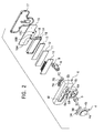
- Fig. 2 is an exploded perspective view of the operating device shown in Fig. 1 .
- Fig. 3 is a block diagram of an electronic system according to the embodiment.
- Fig. 4 is a schematic diagram illustrating a force feedback pattern for an airflow rate setting of an automotive air conditioner according to the embodiment.
- Fig. 5 is a schematic diagram illustrating a force feedback pattern for a temperature setting of the automotive air conditioner according to the embodiment.
- Fig. 6 is a schematic diagram illustrating a force feedback pattern for an air outlet setting of the automotive air conditioner according to the embodiment.
- the device includes an operating unit 1.
- the operating unit 1 includes a display unit 2, which has a plurality of closely arranged display sections, for example, first to third display sections 2A to 2C.
- the first to third display sections 2A to 2C display conditions of a plurality of control items, for example, a set value of an airflow rate, a set value of temperature, and a set mode of an air outlet, respectively.
- the first display section 2A displays an indicator, "AUTO", which indicates an automatic operation of airflow rates, or, for example, numbers “0" to “6” and bars between the numbers, which indicate six levels of the airflow rate. That is, when the automatic operation is selected, only the indicator "AUTO” is illuminated.
- all the numbers “0” to “6” and all the bars up to the number of the set value are illuminated. For example, if a set value "3" is selected for the airflow rate, all the numbers “0” to “6", a bar between the numbers “0” and “1”, a bar between the numbers "1” and “2”, and a bar between the numbers "2" and "3" are illuminated.
- the second display section 2B displays a digital number indicating the set temperature, which ranges from a minimum of 16°C to a maximum of 30° C in steps of 1°C.
- the third display section 2C displays a set mode of the air outlet by lighting arrows, each of which indicates the airflow direction to a face, a body, or feet.
- the set mode includes an airflow to the feet, an airflow to the feet and body, an airflow to the body, an airflow to the body and face, and an airflow to the face.
- a selection unit for selecting a control item displayed in the display section is disposed. That is, first to third push selection buttons 3A to 3C are respectively disposed in these neighboring areas. Specifically, in the neighboring area under the first display section 2A, the first selection button 3A is disposed so as to select an airflow rate as the control item. Similarly, in the neighboring area under the second display section 2B, the second selection button 3B is disposed so as to select temperature as the control item. Furthermore, in the neighboring area under the third display section 2C, the third selection button 3C is disposed so as to select an air outlet as the control item.
- a setting unit common to all the control items is disposed so as to change a setting for the selected control item.
- a rotary knob 4 is disposed in this area.
- the primary shape of the rotary knob 4 is circular in cross-section in the direction orthogonal to its rotational axis.
- the rotary knob 4 is rotationally operated about the axis of the circle.
- a protrusion 4a extending outwardly (from the back to front side of the page) is formed, and a plurality of ridges 4b are formed on the external peripheral surface of the protrusion 4a so as to serve as a slip stopper when operator's fingers hold the protrusion 4a.
- the operating unit 1 also includes a front cover 6 and a back cover 17, both of which form a casing.
- the front cover 6 includes sliding holes 6a to 6c into which the respective first to third selection buttons 3A to 3C are slidably fitted; a recess 6e into which the rotary knob 4 is slidably fitted; a shaft hole 6d formed at the center of the recess 6e, to which a holder 5 that secures the rotary knob 4 with a motor 8 is rotatably inserted; and a frame 6f, which defines the shape of a display unit 2.
- the casing composed of the front cover 6 and the back cover 17 accommodates a printed circuit board 15, on which first to third push button switches 16A to 16C are mounted.
- the printed circuit board 15 is secured with the back cover 17.
- the first to third selection buttons 3A to 3C are supported by first to third button holders 7A to 7C, respectively.
- the first to third selection buttons 3A to 3C push the first to third push button switches 16A to 16C via the first to third button holders 7A to 7C, respectively.
- the casing accommodates force feedback means that provides force feedback to the rotary knob 4, that is, the motor 8 that provides a rotational force to the rotary knob 4.
- a rotary encoder 9 is attached to the motor 8 to detect a rotational angle of the output shaft of the motor 8, that is, a rotational angle of the rotary knob 4.
- a liquid crystal display (LCD) 10 that forms the display unit 2 whose shape is defined by the frame 6f, a light guide plate 13 which leads light emitted from a chip LED 18 to the LCD 10, light diffusing sheets 11 and 12 disposed between the LCD 10 and the light guide plate 13, and an LCD holder 14 which supports the light guide plate 13 and the light diffusing sheets 11 and 12 and mounts the chip LED 18 on its side surface.
- LCD liquid crystal display
- a control unit 20 includes a CPU 20a, a ROM 20b, and an EEPROM 20c, all of which are powered by a power supply 25.
- the CPU 20a controls the motor 8, the LCD 10, and the automotive air conditioner in response to ON signals from the first to third push button switches 16A to 16C and a detection signal from the rotary encoder 9.
- the CPU 20a also controls the entire control unit 20.
- the ROM 20b pre-stores-control programs and control functions for controlling the motor 8, the LCD 10, the automotive air conditioner, and the entire control unit 20.
- the ROM 20b is pre-installed in the air conditioner, and the unused area of the memory is used to store the control programs for the motor 8 and the LCD 10.
- the EEPROM 20c stores calculated values from the CPU 20a, control modes of a fan motor 23, servo motors 24 (a single servo motor is depicted in the drawing), a cooling unit 26, and a heating unit 27 in the automotive air conditioner, control modes of the LCD 10 and the motor 8 in the operating unit 1, detection values from the rotary encoder 9, and detection values from various sensors used to control the automotive air conditioner.
- the fan motor 23 rotates a fan in the automotive air conditioner.
- the servo motors 24 drive dampers to control an airflow rate through an air outlet.
- patterns of force feedback provided to the rotary knob 4 by the motor 8 are, in particular, determined as shown in Figs. 4 to 6 , which correspond to patterns for an airflow rate setting, a temperature setting, and an air outlet setting, respectively.
- the rotary knob 4 in a force feedback pattern 30 for the airflow rate setting, is used to set an airflow rate, and both operations required to rotate the rotary knob 4 beyond an upper rotational limit 31 and below a lower rotational limit 32 are restricted.
- a rotational force that is reverse to the moving direction is increased so that an operator recognizes that an additional rotation cannot be allowed. If the operator forces the rotary knob 4 to rotate beyond the upper rotational limit 31 or the lower rotational limit 32, the rotary knob 4, when the operator's fingers release it, returns to the position corresponding to the upper rotational limit 3L or the lower rotational limit 32.
- the click sensation 33 is generated such that, when a rotational angle of the rotary knob 4 reaches each angle corresponding to "AUTO", or one of "1" to "6", a click sensation 33, the motor 8 temporarily provides the rotary knob 4 with a rotational force of a predetermined strength in the moving direction of the rotary knob 4, or the motor 8 temporarily provides the rotary knob 4 with a rotational force of a predetermined strength in the moving direction of the rotary knob 4 followed by a temporary rotational force of a predetermined strength in the opposite moving direction.
- Click sensations 43 and 51 which will be described below, are also generated in the same manner.
- the motor 8 provides the rotary knob 4 with a rotational force in the opposite moving direction of the rotary knob 4. As the rotational angle in the direction to increase the airflow rate increases, the rotational force in the opposite direction increases. Additionally, as the rotary knob 4 rotates in the direction to decrease the airflow rate, a resistance force applied to the rotary knob 4 by the motor 8 decreases.
- the rotary knob 4 is used to set a temperature, and both operations to rotate the rotary knob 4 beyond an upper rotational limit 41 and a lower rotational limit 42 are restricted.
- a rotation of the rotary knob 4 is not restricted, that is, unlike the above-described airflow rate setting and temperature setting, a rotational angle range is not set. Every time the rotary knob 4 reaches angles corresponding to setting points of the air outlet, a click sensation 51 is generated in the rotary knob 4.
- the setting device having the above-described structure operates as follows:
- the control unit 20 of the operating unit 1 displays the last set airflow rate, temperature, and air outlet in the first to third display sections 2A to 2C of the display unit 2, respectively.
- the operating unit 1 is in a mode in which neither the setting of the airflow rate, temperature, nor air outlet is changed even though the rotary knob 4 rotates. This mode is referred to as "a display mode".
- a number "3" is displayed as a set value of the airflow rate in the first display section 2A. That is, numbers "0" to "6", a bar between the numbers "0” and “1”, a bar between the numbers "1” and “2”, and a bar between the numbers "2" and "3" are illuminated.
- the first push button switch 16A is pushed via the first button holder 7A.
- the first push button switch 16A delivers an ON signal to the control unit 20.
- control unit 20 controls the operating unit 1 to enter a mode that permits a change in an airflow rate setting, that is, an airflow rate setting mode.
- an airflow rate setting mode that is, an airflow rate setting mode.
- the display unit 2 only a set value of the airflow rate is illuminated in the first display section 2A, whereas a set value of the temperature and a set indicator of the air outlet are not illuminated in the first and second display sections 2B and 2C.
- the control unit 20 controls the LCD 10.
- the set value of the airflow rate displayed in the first display section 2A increases or decreases from the previously set value.
- the indicator of an airflow rate in the first display section 2A is changed in such a way, while the motor 8 is controlled.
- the rotary encoder 9 detects rotational angles corresponding to the indicators "AUTO”, “1", “2”, ..., “6”
- the rotary knob 4 provides the click sensation 33 to the operator.
- the rotary knob 4 reaches the rotational angle corresponding to the number "0”
- the operator receives a click sensation 34 that is stronger than the click sensation 33.
- the operator rotates the rotary knob 4 in the direction that increases the airflow rate, the operator receives a stronger resistance force from the rotary knob 4.
- the operator As the operator rotates the rotary knob 4 in the direction that decreases the airflow rate, the operator receives a weaker resistance force from the rotary knob 4. If the operator attempts to rotate the rotary knob 4 beyond the rotational angle corresponding to the maximum airflow rate "6", the operator receives a strong resistance force from the rotary knob 4, and therefore, the rotational operation is restricted. Also, if the operator attempts to rotate the rotary knob 4 beyond the rotational angle corresponding to the indicator "AUTO" representing the automatic airflow rate operation, the operator receives a strong resistance force from the rotary knob 4, and therefore, the operation is restricted.
- the control unit 20 controls the operating unit 1 to illuminate all indicators of the airflow rate, the temperature, and the air outlet and to return to the display mode in which every setting is unchanged even though the rotary knob 4 rotates.
- control unit 20 controls the fan motor 23 and the servo motors 24 so that the fan is driven so as to rotate at a speed corresponding to the set airflow rate and the damper is also adjusted at a gate opening rate corresponding to the set airflow rate.
- the operating unit 1 is in the display mode.
- the second display section 2B of the display unit 2 displays a set value of temperature, for example, a number "24" which indicates 24°C.
- the second push button switch 16B delivers an ON signal to the control unit 20.
- control unit 20 controls the operating unit 1 to enter a mode that permits a change in the temperature setting, that is, the temperature setting mode.
- the control unit 20 controls the operating unit 1 to enter a mode that permits a change in the temperature setting, that is, the temperature setting mode.
- the display unit 2 only a set value of the temperature is illuminated in the second display section 2B, whereas a set value of the airflow rate and a set indicator of the air outlet disappear in the first and third display sections 2A and 2C.
- the rotary encoder 9 inputs a detection signal to the control unit 20 to control the LCD 10.
- the set value of the temperature displayed in the second display section 2B increases or decreases from the previously set value.
- the number set for temperature in the second display section 2B is increased or decreased in such a way, while the motor 8 is controlled.
- the rotary encoder 9 detects a rotational angle change corresponding to 1°C, the rotary knob 4 provides the click sensation 44 to the operator.
- control unit 20 controls the operating unit 1 to illuminate all indicators of the airflow rate, the temperature, and the air outlet and to return to the display mode in which every setting is unchanged even though the rotary knob 4 rotates.
- control unit 20 controls the automotive air conditioner in accordance with the set value. That is, the heating unit 27, when a heating is selected, is controlled, while the cooling unit 26, when a cooling mode is selected, is controlled.
- the operating unit 1 is in the display mode.
- the third display section 2C of the display unit 2 displays a set mode of the air outlet, for example, an indicator of airflow to a body.
- the third push button switch 16C delivers an ON signal to the control unit 20.
- control unit 20 controls the operating unit 1 to enter a mode that permits a change in the air outlet setting, that is, the air outlet setting mode.
- the control unit 20 controls the operating unit 1 to enter a mode that permits a change in the air outlet setting, that is, the air outlet setting mode.
- the display unit 2 only an indicator of the air outlet is illuminated in the third display section 2C, whereas a set value of the temperature in the second display section 2B and a set value of the airflow rate in the first display section 2A disappear.
- the rotary encoder 9 inputs a detection signal to the control unit 20 to control the LCD 10.
- the previously set indicator, airflow to the body, displayed in the third display section 2C is changed to another indicator of the air outlet setting.
- the indicator of airflow to the body is switched to an indicator of airflow to the body and face, an indicator of airflow to the face, and an indicator of airflow to the feet.
- the indicator of airflow to the body is switched to an indicator of airflow to the feet and body, an indicator of airflow to the feet, and an indicator of airflow to the face.
- the air outlet setting indicator in the third display section 2C is changed in such a way, while the motor 8 is controlled.
- the rotary encoder 9 detects a rotational angle corresponding to airflow to the feet, airflow to the feet and body, airflow to the body, airflow to the body and face, or airflow to the face, the rotary knob 4 provides the click sensation 51 to the operator.
- control unit 20 controls the operating unit 1 so as to illuminate all indicators of the airflow rate, the temperature, and the air outlet and to return to the display mode in which every setting is unchanged even though the rotary knob 4 rotates.
- control unit 20 controls the servo motors 24 so as to open dampers corresponding to the current air outlet setting and close the other dampers.
- This embodiment provides the following advantages.
- the rotation of the rotary knob 4 is restricted.
- the rotation of the rotary knob 4 is not restricted. Accordingly, the sensation provided by the rotary knob 4 during a temperature setting is reliably distinguished from the sensation provided by the rotary knob 4 during an air outlet setting. As a result, the operator can easily recognize which control item the operator is attempting to set.
- a sensation of resistance received from the rotation of the rotary knob 4 is increased or decreased in accordance with an increase or decrease in the rotational angle of the rotary knob 4.
- a sensation of resistance received from the rotation of the rotary knob 4 is not increased or decreased in accordance with an increase or decrease in the rotational angle of the rotary knob 4. Accordingly, the sensation provided by the rotary knob 4 during a temperature setting is reliably distinguished from the sensation provided by the rotary knob 4 during an airflow rate setting. As a result, the operator can easily recognize which control item the operator is attempting to set.
- the present invention is not intended to be limited to such an application.
- the present invention may be applied to in-car setting devices to set the tone and volume of sound from electronic devices, such as car radios, compact disc (CD) players, and mini disc (MD) players.
- electronic devices that may be suitably applied to the present invention include, but are not limited to, in-car electronic devices which require a driver to manipulate the electronic devices without looking at operating units of the electronic devices.
Landscapes
- Physics & Mathematics (AREA)
- Engineering & Computer Science (AREA)
- Thermal Sciences (AREA)
- Mechanical Engineering (AREA)
- General Physics & Mathematics (AREA)
- Automation & Control Theory (AREA)
- Air-Conditioning For Vehicles (AREA)
- Mechanical Control Devices (AREA)
- Feedback Control In General (AREA)
Applications Claiming Priority (2)
| Application Number | Priority Date | Filing Date | Title |
|---|---|---|---|
| JP2003314117 | 2003-09-05 | ||
| JP2003314117A JP4249576B2 (ja) | 2003-09-05 | 2003-09-05 | 力覚付与型設定装置 |
Publications (3)
| Publication Number | Publication Date |
|---|---|
| EP1513038A2 EP1513038A2 (en) | 2005-03-09 |
| EP1513038A3 EP1513038A3 (en) | 2010-09-22 |
| EP1513038B1 true EP1513038B1 (en) | 2012-09-12 |
Family
ID=34131903
Family Applications (1)
| Application Number | Title | Priority Date | Filing Date |
|---|---|---|---|
| EP04020883A Expired - Lifetime EP1513038B1 (en) | 2003-09-05 | 2004-09-02 | Setting device of a force feedback type |
Country Status (5)
| Country | Link |
|---|---|
| US (1) | US7086243B2 (ja) |
| EP (1) | EP1513038B1 (ja) |
| JP (1) | JP4249576B2 (ja) |
| KR (1) | KR100579612B1 (ja) |
| CN (1) | CN1282064C (ja) |
Families Citing this family (15)
| Publication number | Priority date | Publication date | Assignee | Title |
|---|---|---|---|---|
| JP2005332157A (ja) * | 2004-05-19 | 2005-12-02 | Alps Electric Co Ltd | 力覚付与型入力装置 |
| JP2006199199A (ja) * | 2005-01-21 | 2006-08-03 | Kojima Press Co Ltd | 車両用空調コントローラ |
| KR100692728B1 (ko) * | 2005-10-18 | 2007-03-09 | 현대자동차주식회사 | 자동차용 오디오시스템의 볼륨조절노브 장치 |
| US8528878B2 (en) | 2006-05-23 | 2013-09-10 | Behr-Hella Thermocontrol Gmbh | Rotary control unit, in particular nominal value rotary control unit, for a vehicle heating system and in particular vehicle air conditioning system |
| JP4830672B2 (ja) * | 2006-06-29 | 2011-12-07 | トヨタ自動車株式会社 | 車載機器制御装置および該装置を用いた車載機器設定方法 |
| CN100424620C (zh) * | 2006-12-22 | 2008-10-08 | 上海威乐汽车空调器有限公司 | 一种用汽车空调器旋钮调节温度或风量的方法 |
| WO2008113410A1 (en) * | 2007-03-19 | 2008-09-25 | Maquet Critical Care Ab | Method and device for manual input and haptic output of patient critical operating parameters in a breathing apparatus |
| JP5662652B2 (ja) * | 2009-05-11 | 2015-02-04 | 株式会社プロテックデザイン | 触感付与装置及び電子機器 |
| FR2950166B1 (fr) * | 2009-09-16 | 2015-07-17 | Dav | Dispositif de commande rotatif a retour haptique |
| KR101920227B1 (ko) | 2011-08-22 | 2018-11-20 | 가이트라인 에이에스 | 신발 및 신발 제조 방법 |
| EP2604742B1 (de) | 2011-12-13 | 2017-01-25 | Miele & Cie. KG | Bedienelement für ein Haushaltsgerät, Bedieneinheit für ein solches Haushaltsgerät mit einem solchen Bedienelement und Haushaltsgerät mit einer solchen Bedieneinheit und/ oder einem solchen Bedienelement |
| US20140116181A1 (en) * | 2012-10-04 | 2014-05-01 | Honda Motor Co., Ltd. | Climate control system and method |
| US11254012B2 (en) | 2016-09-14 | 2022-02-22 | Keba Ag | Control device and control method for industrial machines having controlled movement drives |
| KR102639079B1 (ko) * | 2018-08-22 | 2024-02-22 | 현대자동차주식회사 | 차량용 조작 제어 장치 및 그의 동작 방법 |
| JP7590636B2 (ja) * | 2020-08-21 | 2024-11-27 | 株式会社デンソーウェーブ | 回転型操作装置 |
Family Cites Families (13)
| Publication number | Priority date | Publication date | Assignee | Title |
|---|---|---|---|---|
| DE19609390C2 (de) * | 1996-02-29 | 2002-05-23 | Siemens Ag | Bedienvorrichtung mit mehreren Stellgliedern |
| US6636197B1 (en) * | 1996-11-26 | 2003-10-21 | Immersion Corporation | Haptic feedback effects for control, knobs and other interface devices |
| US6154201A (en) * | 1996-11-26 | 2000-11-28 | Immersion Corporation | Control knob with multiple degrees of freedom and force feedback |
| US6686911B1 (en) * | 1996-11-26 | 2004-02-03 | Immersion Corporation | Control knob with control modes and force feedback |
| DE19824149A1 (de) * | 1998-05-29 | 1999-12-02 | Nokia Mobile Phones Ltd | Drehsteller für elektrische oder elektronische Geräte |
| US7038667B1 (en) * | 1998-10-26 | 2006-05-02 | Immersion Corporation | Mechanisms for control knobs and other interface devices |
| JP2001109558A (ja) * | 1999-08-18 | 2001-04-20 | Immersion Corp | 制御ノブ及び他のインターフェース装置に対する機構 |
| JP2001166804A (ja) * | 1999-12-10 | 2001-06-22 | Sony Corp | 学習式動作制御装置およびその方法、並びに提供媒体 |
| JP2002189560A (ja) | 2000-12-22 | 2002-07-05 | Alps Electric Co Ltd | 手動入力装置及びこれを用いた車載機器制御装置 |
| JP4061105B2 (ja) * | 2002-03-29 | 2008-03-12 | アルプス電気株式会社 | 力覚付与装置 |
| JP4310127B2 (ja) * | 2003-04-14 | 2009-08-05 | アルプス電気株式会社 | 力覚付与型入力装置 |
| JP2004342018A (ja) * | 2003-05-19 | 2004-12-02 | Alps Electric Co Ltd | 力覚付与型入力装置 |
| JP2004359103A (ja) * | 2003-06-04 | 2004-12-24 | Alps Electric Co Ltd | 車載電気機器制御装置 |
-
2003
- 2003-09-05 JP JP2003314117A patent/JP4249576B2/ja not_active Expired - Fee Related
-
2004
- 2004-07-26 KR KR1020040058240A patent/KR100579612B1/ko not_active Expired - Fee Related
- 2004-09-02 EP EP04020883A patent/EP1513038B1/en not_active Expired - Lifetime
- 2004-09-02 US US10/932,673 patent/US7086243B2/en not_active Expired - Fee Related
- 2004-09-03 CN CNB2004100751420A patent/CN1282064C/zh not_active Expired - Fee Related
Also Published As
| Publication number | Publication date |
|---|---|
| CN1282064C (zh) | 2006-10-25 |
| KR20050025242A (ko) | 2005-03-14 |
| EP1513038A3 (en) | 2010-09-22 |
| KR100579612B1 (ko) | 2006-05-12 |
| EP1513038A2 (en) | 2005-03-09 |
| JP4249576B2 (ja) | 2009-04-02 |
| JP2005081908A (ja) | 2005-03-31 |
| US7086243B2 (en) | 2006-08-08 |
| CN1591306A (zh) | 2005-03-09 |
| US20050052151A1 (en) | 2005-03-10 |
Similar Documents
| Publication | Publication Date | Title |
|---|---|---|
| EP1513038B1 (en) | Setting device of a force feedback type | |
| JP3920559B2 (ja) | 手動入力装置 | |
| US5821935A (en) | Graphical user interface with electronic feature access | |
| EP1569073B1 (en) | Single knob multifunction controller and display unit | |
| US5916288A (en) | Multi-functional control switch arrangement | |
| US10649556B2 (en) | Control knob for controlling operation of a machine | |
| US10838525B2 (en) | Control knob for controlling operation of a machine | |
| KR101286916B1 (ko) | 차량용 입력 조작 장치 | |
| JP2012053801A (ja) | 車両用操作装置 | |
| JP3839191B2 (ja) | 車載用入力装置 | |
| JP2002539010A (ja) | 操作装置 | |
| EP2033821B9 (en) | Vehicle-mounted device controlling device and vehicle-mounted device setting method using the same | |
| US7086292B2 (en) | Force-feedback input device | |
| JP2004359102A (ja) | 車載電気機器制御装置 | |
| JP2005096515A (ja) | 車載用入力装置 | |
| JP2005081906A (ja) | 車載用設定装置 | |
| JP3790372B2 (ja) | 入力装置 | |
| JPH10172390A (ja) | 車両用エアコンディショナーの操作装置 | |
| JP4238098B2 (ja) | 操作感覚付与型入力装置 | |
| KR20030008060A (ko) | 휴대용 컴퓨터 및 휴대용 컴퓨터의 냉각팬 제어방법 | |
| JP4285393B2 (ja) | 車両用パワーウインドウ制御装置 | |
| JP2005081909A (ja) | 車載用設定装置 | |
| KR20090112781A (ko) | 차량의 히터 컨트롤 패널 | |
| JPH0848134A (ja) | 空調装置の作動表示方法 | |
| JPH1132942A (ja) | 手乾燥機の制御装置 |
Legal Events
| Date | Code | Title | Description |
|---|---|---|---|
| PUAI | Public reference made under article 153(3) epc to a published international application that has entered the european phase |
Free format text: ORIGINAL CODE: 0009012 |
|
| AK | Designated contracting states |
Kind code of ref document: A2 Designated state(s): AT BE BG CH CY CZ DE DK EE ES FI FR GB GR HU IE IT LI LU MC NL PL PT RO SE SI SK TR |
|
| AX | Request for extension of the european patent |
Extension state: AL HR LT LV MK |
|
| PUAL | Search report despatched |
Free format text: ORIGINAL CODE: 0009013 |
|
| AK | Designated contracting states |
Kind code of ref document: A3 Designated state(s): AT BE BG CH CY CZ DE DK EE ES FI FR GB GR HU IE IT LI LU MC NL PL PT RO SE SI SK TR |
|
| AX | Request for extension of the european patent |
Extension state: AL HR LT LV MK |
|
| 17P | Request for examination filed |
Effective date: 20110322 |
|
| AKX | Designation fees paid |
Designated state(s): DE FR GB IT |
|
| 17Q | First examination report despatched |
Effective date: 20110517 |
|
| GRAP | Despatch of communication of intention to grant a patent |
Free format text: ORIGINAL CODE: EPIDOSNIGR1 |
|
| GRAS | Grant fee paid |
Free format text: ORIGINAL CODE: EPIDOSNIGR3 |
|
| GRAA | (expected) grant |
Free format text: ORIGINAL CODE: 0009210 |
|
| AK | Designated contracting states |
Kind code of ref document: B1 Designated state(s): DE FR GB IT |
|
| REG | Reference to a national code |
Ref country code: GB Ref legal event code: FG4D |
|
| REG | Reference to a national code |
Ref country code: DE Ref legal event code: R096 Ref document number: 602004039266 Country of ref document: DE Effective date: 20121108 |
|
| PLBE | No opposition filed within time limit |
Free format text: ORIGINAL CODE: 0009261 |
|
| STAA | Information on the status of an ep patent application or granted ep patent |
Free format text: STATUS: NO OPPOSITION FILED WITHIN TIME LIMIT |
|
| 26N | No opposition filed |
Effective date: 20130613 |
|
| PG25 | Lapsed in a contracting state [announced via postgrant information from national office to epo] |
Ref country code: IT Free format text: LAPSE BECAUSE OF FAILURE TO SUBMIT A TRANSLATION OF THE DESCRIPTION OR TO PAY THE FEE WITHIN THE PRESCRIBED TIME-LIMIT Effective date: 20120912 |
|
| REG | Reference to a national code |
Ref country code: DE Ref legal event code: R097 Ref document number: 602004039266 Country of ref document: DE Effective date: 20130613 |
|
| PGFP | Annual fee paid to national office [announced via postgrant information from national office to epo] |
Ref country code: DE Payment date: 20130930 Year of fee payment: 10 |
|
| GBPC | Gb: european patent ceased through non-payment of renewal fee |
Effective date: 20130902 |
|
| REG | Reference to a national code |
Ref country code: FR Ref legal event code: ST Effective date: 20140530 |
|
| PG25 | Lapsed in a contracting state [announced via postgrant information from national office to epo] |
Ref country code: GB Free format text: LAPSE BECAUSE OF NON-PAYMENT OF DUE FEES Effective date: 20130902 |
|
| PG25 | Lapsed in a contracting state [announced via postgrant information from national office to epo] |
Ref country code: FR Free format text: LAPSE BECAUSE OF NON-PAYMENT OF DUE FEES Effective date: 20130930 |
|
| REG | Reference to a national code |
Ref country code: DE Ref legal event code: R119 Ref document number: 602004039266 Country of ref document: DE |
|
| PG25 | Lapsed in a contracting state [announced via postgrant information from national office to epo] |
Ref country code: DE Free format text: LAPSE BECAUSE OF NON-PAYMENT OF DUE FEES Effective date: 20150401 |