EP1512860A2 - Système de purification de gaz d'échappement - Google Patents
Système de purification de gaz d'échappement Download PDFInfo
- Publication number
- EP1512860A2 EP1512860A2 EP04103973A EP04103973A EP1512860A2 EP 1512860 A2 EP1512860 A2 EP 1512860A2 EP 04103973 A EP04103973 A EP 04103973A EP 04103973 A EP04103973 A EP 04103973A EP 1512860 A2 EP1512860 A2 EP 1512860A2
- Authority
- EP
- European Patent Office
- Prior art keywords
- exhaust gas
- exhaust
- temperature
- gas temperature
- throttling
- Prior art date
- Legal status (The legal status is an assumption and is not a legal conclusion. Google has not performed a legal analysis and makes no representation as to the accuracy of the status listed.)
- Granted
Links
Images


Classifications
-
- F—MECHANICAL ENGINEERING; LIGHTING; HEATING; WEAPONS; BLASTING
- F01—MACHINES OR ENGINES IN GENERAL; ENGINE PLANTS IN GENERAL; STEAM ENGINES
- F01N—GAS-FLOW SILENCERS OR EXHAUST APPARATUS FOR MACHINES OR ENGINES IN GENERAL; GAS-FLOW SILENCERS OR EXHAUST APPARATUS FOR INTERNAL-COMBUSTION ENGINES
- F01N3/00—Exhaust or silencing apparatus having means for purifying, rendering innocuous, or otherwise treating exhaust
- F01N3/02—Exhaust or silencing apparatus having means for purifying, rendering innocuous, or otherwise treating exhaust for cooling, or for removing solid constituents of, exhaust
- F01N3/021—Exhaust or silencing apparatus having means for purifying, rendering innocuous, or otherwise treating exhaust for cooling, or for removing solid constituents of, exhaust by means of filters
- F01N3/023—Exhaust or silencing apparatus having means for purifying, rendering innocuous, or otherwise treating exhaust for cooling, or for removing solid constituents of, exhaust by means of filters using means for regenerating the filters, e.g. by burning trapped particles
- F01N3/0235—Exhaust or silencing apparatus having means for purifying, rendering innocuous, or otherwise treating exhaust for cooling, or for removing solid constituents of, exhaust by means of filters using means for regenerating the filters, e.g. by burning trapped particles using exhaust gas throttling means
-
- F—MECHANICAL ENGINEERING; LIGHTING; HEATING; WEAPONS; BLASTING
- F01—MACHINES OR ENGINES IN GENERAL; ENGINE PLANTS IN GENERAL; STEAM ENGINES
- F01N—GAS-FLOW SILENCERS OR EXHAUST APPARATUS FOR MACHINES OR ENGINES IN GENERAL; GAS-FLOW SILENCERS OR EXHAUST APPARATUS FOR INTERNAL-COMBUSTION ENGINES
- F01N13/00—Exhaust or silencing apparatus characterised by constructional features
- F01N13/009—Exhaust or silencing apparatus characterised by constructional features having two or more separate purifying devices arranged in series
- F01N13/0097—Exhaust or silencing apparatus characterised by constructional features having two or more separate purifying devices arranged in series the purifying devices are arranged in a single housing
-
- F—MECHANICAL ENGINEERING; LIGHTING; HEATING; WEAPONS; BLASTING
- F01—MACHINES OR ENGINES IN GENERAL; ENGINE PLANTS IN GENERAL; STEAM ENGINES
- F01N—GAS-FLOW SILENCERS OR EXHAUST APPARATUS FOR MACHINES OR ENGINES IN GENERAL; GAS-FLOW SILENCERS OR EXHAUST APPARATUS FOR INTERNAL-COMBUSTION ENGINES
- F01N3/00—Exhaust or silencing apparatus having means for purifying, rendering innocuous, or otherwise treating exhaust
- F01N3/02—Exhaust or silencing apparatus having means for purifying, rendering innocuous, or otherwise treating exhaust for cooling, or for removing solid constituents of, exhaust
- F01N3/021—Exhaust or silencing apparatus having means for purifying, rendering innocuous, or otherwise treating exhaust for cooling, or for removing solid constituents of, exhaust by means of filters
- F01N3/023—Exhaust or silencing apparatus having means for purifying, rendering innocuous, or otherwise treating exhaust for cooling, or for removing solid constituents of, exhaust by means of filters using means for regenerating the filters, e.g. by burning trapped particles
- F01N3/0231—Exhaust or silencing apparatus having means for purifying, rendering innocuous, or otherwise treating exhaust for cooling, or for removing solid constituents of, exhaust by means of filters using means for regenerating the filters, e.g. by burning trapped particles using special exhaust apparatus upstream of the filter for producing nitrogen dioxide, e.g. for continuous filter regeneration systems [CRT]
-
- F—MECHANICAL ENGINEERING; LIGHTING; HEATING; WEAPONS; BLASTING
- F01—MACHINES OR ENGINES IN GENERAL; ENGINE PLANTS IN GENERAL; STEAM ENGINES
- F01N—GAS-FLOW SILENCERS OR EXHAUST APPARATUS FOR MACHINES OR ENGINES IN GENERAL; GAS-FLOW SILENCERS OR EXHAUST APPARATUS FOR INTERNAL-COMBUSTION ENGINES
- F01N3/00—Exhaust or silencing apparatus having means for purifying, rendering innocuous, or otherwise treating exhaust
- F01N3/02—Exhaust or silencing apparatus having means for purifying, rendering innocuous, or otherwise treating exhaust for cooling, or for removing solid constituents of, exhaust
- F01N3/021—Exhaust or silencing apparatus having means for purifying, rendering innocuous, or otherwise treating exhaust for cooling, or for removing solid constituents of, exhaust by means of filters
- F01N3/033—Exhaust or silencing apparatus having means for purifying, rendering innocuous, or otherwise treating exhaust for cooling, or for removing solid constituents of, exhaust by means of filters in combination with other devices
- F01N3/035—Exhaust or silencing apparatus having means for purifying, rendering innocuous, or otherwise treating exhaust for cooling, or for removing solid constituents of, exhaust by means of filters in combination with other devices with catalytic reactors
-
- F—MECHANICAL ENGINEERING; LIGHTING; HEATING; WEAPONS; BLASTING
- F01—MACHINES OR ENGINES IN GENERAL; ENGINE PLANTS IN GENERAL; STEAM ENGINES
- F01N—GAS-FLOW SILENCERS OR EXHAUST APPARATUS FOR MACHINES OR ENGINES IN GENERAL; GAS-FLOW SILENCERS OR EXHAUST APPARATUS FOR INTERNAL-COMBUSTION ENGINES
- F01N9/00—Electrical control of exhaust gas treating apparatus
- F01N9/002—Electrical control of exhaust gas treating apparatus of filter regeneration
-
- F—MECHANICAL ENGINEERING; LIGHTING; HEATING; WEAPONS; BLASTING
- F02—COMBUSTION ENGINES; HOT-GAS OR COMBUSTION-PRODUCT ENGINE PLANTS
- F02D—CONTROLLING COMBUSTION ENGINES
- F02D41/00—Electrical control of supply of combustible mixture or its constituents
- F02D41/02—Circuit arrangements for generating control signals
- F02D41/021—Introducing corrections for particular conditions exterior to the engine
- F02D41/0235—Introducing corrections for particular conditions exterior to the engine in relation with the state of the exhaust gas treating apparatus
- F02D41/027—Introducing corrections for particular conditions exterior to the engine in relation with the state of the exhaust gas treating apparatus to purge or regenerate the exhaust gas treating apparatus
- F02D41/029—Introducing corrections for particular conditions exterior to the engine in relation with the state of the exhaust gas treating apparatus to purge or regenerate the exhaust gas treating apparatus the exhaust gas treating apparatus being a particulate filter
-
- F—MECHANICAL ENGINEERING; LIGHTING; HEATING; WEAPONS; BLASTING
- F02—COMBUSTION ENGINES; HOT-GAS OR COMBUSTION-PRODUCT ENGINE PLANTS
- F02D—CONTROLLING COMBUSTION ENGINES
- F02D41/00—Electrical control of supply of combustible mixture or its constituents
- F02D41/30—Controlling fuel injection
- F02D41/38—Controlling fuel injection of the high pressure type
- F02D41/40—Controlling fuel injection of the high pressure type with means for controlling injection timing or duration
- F02D41/401—Controlling injection timing
-
- F—MECHANICAL ENGINEERING; LIGHTING; HEATING; WEAPONS; BLASTING
- F02—COMBUSTION ENGINES; HOT-GAS OR COMBUSTION-PRODUCT ENGINE PLANTS
- F02D—CONTROLLING COMBUSTION ENGINES
- F02D41/00—Electrical control of supply of combustible mixture or its constituents
- F02D41/30—Controlling fuel injection
- F02D41/38—Controlling fuel injection of the high pressure type
- F02D41/40—Controlling fuel injection of the high pressure type with means for controlling injection timing or duration
- F02D41/402—Multiple injections
- F02D41/403—Multiple injections with pilot injections
-
- F—MECHANICAL ENGINEERING; LIGHTING; HEATING; WEAPONS; BLASTING
- F02—COMBUSTION ENGINES; HOT-GAS OR COMBUSTION-PRODUCT ENGINE PLANTS
- F02D—CONTROLLING COMBUSTION ENGINES
- F02D9/00—Controlling engines by throttling air or fuel-and-air induction conduits or exhaust conduits
- F02D9/04—Controlling engines by throttling air or fuel-and-air induction conduits or exhaust conduits concerning exhaust conduits
- F02D9/06—Exhaust brakes
-
- F—MECHANICAL ENGINEERING; LIGHTING; HEATING; WEAPONS; BLASTING
- F01—MACHINES OR ENGINES IN GENERAL; ENGINE PLANTS IN GENERAL; STEAM ENGINES
- F01N—GAS-FLOW SILENCERS OR EXHAUST APPARATUS FOR MACHINES OR ENGINES IN GENERAL; GAS-FLOW SILENCERS OR EXHAUST APPARATUS FOR INTERNAL-COMBUSTION ENGINES
- F01N2260/00—Exhaust treating devices having provisions not otherwise provided for
- F01N2260/14—Exhaust treating devices having provisions not otherwise provided for for modifying or adapting flow area or back-pressure
-
- F—MECHANICAL ENGINEERING; LIGHTING; HEATING; WEAPONS; BLASTING
- F01—MACHINES OR ENGINES IN GENERAL; ENGINE PLANTS IN GENERAL; STEAM ENGINES
- F01N—GAS-FLOW SILENCERS OR EXHAUST APPARATUS FOR MACHINES OR ENGINES IN GENERAL; GAS-FLOW SILENCERS OR EXHAUST APPARATUS FOR INTERNAL-COMBUSTION ENGINES
- F01N2430/00—Influencing exhaust purification, e.g. starting of catalytic reaction, filter regeneration, or the like, by controlling engine operating characteristics
- F01N2430/08—Influencing exhaust purification, e.g. starting of catalytic reaction, filter regeneration, or the like, by controlling engine operating characteristics by modifying ignition or injection timing
-
- F—MECHANICAL ENGINEERING; LIGHTING; HEATING; WEAPONS; BLASTING
- F01—MACHINES OR ENGINES IN GENERAL; ENGINE PLANTS IN GENERAL; STEAM ENGINES
- F01N—GAS-FLOW SILENCERS OR EXHAUST APPARATUS FOR MACHINES OR ENGINES IN GENERAL; GAS-FLOW SILENCERS OR EXHAUST APPARATUS FOR INTERNAL-COMBUSTION ENGINES
- F01N2560/00—Exhaust systems with means for detecting or measuring exhaust gas components or characteristics
- F01N2560/06—Exhaust systems with means for detecting or measuring exhaust gas components or characteristics the means being a temperature sensor
-
- F—MECHANICAL ENGINEERING; LIGHTING; HEATING; WEAPONS; BLASTING
- F01—MACHINES OR ENGINES IN GENERAL; ENGINE PLANTS IN GENERAL; STEAM ENGINES
- F01N—GAS-FLOW SILENCERS OR EXHAUST APPARATUS FOR MACHINES OR ENGINES IN GENERAL; GAS-FLOW SILENCERS OR EXHAUST APPARATUS FOR INTERNAL-COMBUSTION ENGINES
- F01N2560/00—Exhaust systems with means for detecting or measuring exhaust gas components or characteristics
- F01N2560/08—Exhaust systems with means for detecting or measuring exhaust gas components or characteristics the means being a pressure sensor
-
- F—MECHANICAL ENGINEERING; LIGHTING; HEATING; WEAPONS; BLASTING
- F02—COMBUSTION ENGINES; HOT-GAS OR COMBUSTION-PRODUCT ENGINE PLANTS
- F02B—INTERNAL-COMBUSTION PISTON ENGINES; COMBUSTION ENGINES IN GENERAL
- F02B29/00—Engines characterised by provision for charging or scavenging not provided for in groups F02B25/00, F02B27/00 or F02B33/00 - F02B39/00; Details thereof
- F02B29/04—Cooling of air intake supply
- F02B29/0406—Layout of the intake air cooling or coolant circuit
-
- F—MECHANICAL ENGINEERING; LIGHTING; HEATING; WEAPONS; BLASTING
- F02—COMBUSTION ENGINES; HOT-GAS OR COMBUSTION-PRODUCT ENGINE PLANTS
- F02B—INTERNAL-COMBUSTION PISTON ENGINES; COMBUSTION ENGINES IN GENERAL
- F02B37/00—Engines characterised by provision of pumps driven at least for part of the time by exhaust
-
- F—MECHANICAL ENGINEERING; LIGHTING; HEATING; WEAPONS; BLASTING
- F02—COMBUSTION ENGINES; HOT-GAS OR COMBUSTION-PRODUCT ENGINE PLANTS
- F02D—CONTROLLING COMBUSTION ENGINES
- F02D41/00—Electrical control of supply of combustible mixture or its constituents
- F02D41/02—Circuit arrangements for generating control signals
- F02D41/021—Introducing corrections for particular conditions exterior to the engine
- F02D41/0235—Introducing corrections for particular conditions exterior to the engine in relation with the state of the exhaust gas treating apparatus
- F02D41/024—Introducing corrections for particular conditions exterior to the engine in relation with the state of the exhaust gas treating apparatus to increase temperature of the exhaust gas treating apparatus
- F02D41/0245—Introducing corrections for particular conditions exterior to the engine in relation with the state of the exhaust gas treating apparatus to increase temperature of the exhaust gas treating apparatus by increasing temperature of the exhaust gas leaving the engine
-
- F—MECHANICAL ENGINEERING; LIGHTING; HEATING; WEAPONS; BLASTING
- F02—COMBUSTION ENGINES; HOT-GAS OR COMBUSTION-PRODUCT ENGINE PLANTS
- F02D—CONTROLLING COMBUSTION ENGINES
- F02D41/00—Electrical control of supply of combustible mixture or its constituents
- F02D41/30—Controlling fuel injection
- F02D41/38—Controlling fuel injection of the high pressure type
- F02D41/40—Controlling fuel injection of the high pressure type with means for controlling injection timing or duration
- F02D41/402—Multiple injections
-
- Y—GENERAL TAGGING OF NEW TECHNOLOGICAL DEVELOPMENTS; GENERAL TAGGING OF CROSS-SECTIONAL TECHNOLOGIES SPANNING OVER SEVERAL SECTIONS OF THE IPC; TECHNICAL SUBJECTS COVERED BY FORMER USPC CROSS-REFERENCE ART COLLECTIONS [XRACs] AND DIGESTS
- Y02—TECHNOLOGIES OR APPLICATIONS FOR MITIGATION OR ADAPTATION AGAINST CLIMATE CHANGE
- Y02T—CLIMATE CHANGE MITIGATION TECHNOLOGIES RELATED TO TRANSPORTATION
- Y02T10/00—Road transport of goods or passengers
- Y02T10/10—Internal combustion engine [ICE] based vehicles
- Y02T10/40—Engine management systems
Definitions
- the present invention relates to an exhaust gas purifying system for purifying the exhaust gas of an engine by providing a diesel particulate filter.
- the restriction of the discharge quantity of particulate matter (hereafter referred to as PM) to be discharged from a diesel engine has been enhanced year by year together with NOx, CO, and HC. Only an improvement of an engine cannot; respond to the enhancement of the legal restriction. Therefore, a technique is developed, which reduces the quantity of the PM to be discharged to the open air by collecting the quantity of the PM using a filter referred to as diesel particulate filter (hereafter referred to as DPF).
- DPF diesel particulate filter
- the DPF for directly collecting the PM includes a monolith honeycomb wall flow type filter made of ceramic and a fiber-type filter obtained by processing ceramic or metal into fiber.
- the exhaust gas purifying system provided with the above PDF is set in the middle of the exhaust passage of an engine to purify the exhaust gas generated by the engine, similar to other exhaust gas purifying systems.
- the DPF has problems, that is, fuel consumption deteriorates because the exhaust pressure is raised proportionally to the collected quantity of the PM and that a melting loss occurs due to sudden combustion after excessive collection of the PM. Therefore, it is necessary to remove the collected the PM by burning it and regenerate a DPF.
- DPF regenerating methods an electric heater heating type, a burner heating type, and a back washing type are proposed.
- This technique oxidizes the PM with the exhaust heat from the engine to regenerate the DPF by using lower oxidation temperature of the PM using an oxidation catalyst.
- This DPF system is called a continuously regenerating type DPF system because the regeneration of the DPF is basically continuous.
- theses systems are further-simplified into a single DPF system, which has the advantage of simplifying the regeneration control.
- the NO 2 generation type DPF system 1X is shown in Fig. 7 as an example of a system for oxidizing the PM by NO 2 (nitrogen dioxide) to regenerate a DPF.
- an oxidation catalyst 3Aa is set to the upstream side of the common wall flow filter 3Ab.
- This oxidation catalyst 3Aa oxidizes NO (nitrogen monoxide) in the exhaust gas. Therefore, most NOx in the exhaust gas becomes NO 2 in the downstream side of the oxidation catalyst 3Aa.
- the PM collected in the filter 3Ab in the downstream side is removed by oxidizing it into CO 2 (carbon dioxide).
- the NO 2 lowers the PM oxidizing temperature (DPF regenerating temperature) because it has a smaller energy barrier than that of Oz. Therefore, the PM combustion continuously occurs through the heat energy in the exhaust gas without using the energy supplied from the outside.
- E denotes a diesel engine
- 2 denotes an exhaust passage
- 4 denotes a fuel pump system
- 5 denotes an electronic control box
- 7 denotes a battery
- 8 denotes a muffler
- 9 denotes a fuel tank, by reference symbols and reference numbers.
- Fig. 8 shows a system 1Y obtained by improving the NO 2 regenerating type DPF system in Fig. 7.
- a porous catalyst coat layer 31 of an oxidation catalyst 32A is applied to a porous wall surface 30 of a wall flow filter 3B.
- the system 1Y is set up so as to perform oxidation of NO and oxidation of the PM by NO 2 generated by the oxidation of NO on the wall surface of the wall flow filter 3B. This configuration simplifies the system.
- Fig. 9 shows a continuous regeneration system 1Z.
- a porous catalyst coat layer 31 that comprises the oxidation catalyst 32A and a PM oxidation catalyst 32B such as oxide is applied to the porous wall surface 30 of a wall flow filter 3C.
- the porous catalyst coat layer 31 burns the PM accumulated in the filter 3C at a low temperature.
- the DPF system with these catalysts realizes the continuous regeneration of the PM by using the oxidation reaction of the PM by catalysts and NO 2 , and thereby lowering the oxidation initiation exhaust gas temperature of the PM, compared to that of a common filter.
- the temperature of the DPF is equal to the combustion temperature of the PM or higher when the exhaust gas temperature is approx. 350°C or higher, thereby burning and removing the PM collected in the DPF and realizing the self-regeneration of the DPF.
- the DPF is constituted by the continuously regenerating type DPF system to lower the oxidation initiation exhaust gas temperature of the PM, the exhaust gas temperature of approx. 350°C is still needed. Therefore, the oxidation pf the PM and the self-regeneration of the DPF do not occur when the exhaust gas temperature is lower than approx. 350C, due to a low load operation, an idling operation, and the like.
- a necessary condition for the DPF regeneration is set by calculating the accumulated quantity of the PM in a filter in accordance with an engine operation condition and/or estimating the accumulated quantity of the PM in accordance with the pressure loss of the filter that corresponds to the accumulated quantity of the PM. Then, the DPF regeneration control, which forcibly raises the exhaust gas temperature and burns the accumulated PM for removal, is performed when the necessary condition for the DPF regeneration is satisfied.
- Japanese Patent Laid-Open No. 1988-201309 discloses one of the methods for raising an exhaust gas temperature by throttling exhaust gas together with the use of an EGR valve.
- Japanese Patent Laid-Open No. 1993-81513 discloses a method for controlling the valve opening of an exhaust throttling valve that is set to the downstream side of a trap filter (DPF) so as to keep an exhaust gas temperature in a predetermined regeneration temperature range while regenerating the filter.
- DPF trap filter
- the low exhaust gas temperature means the condition with the exhaust gas temperature of approx. 200°C or lower, such as when an engine is operated at low load and low engine speed for idling and the like.
- An NO 2 regeneration type DPF system with an oxidation catalyst set to the upstream side has the following problems.
- an exhaust gas temperature rises after a state in which the DPF cannot forcibly be regenerated is continued, the fuel accumulated in an oxidation catalyst is suddenly burned. Therefore, the temperature of the oxidation catalyst becomes high, causing deterioration of the catalyst and a melting loss.
- the exhaust gas, the temperature of which is high due to this sudden combustion flows into the DPF at the downstream side. Thereby, the PM accumulated in the DPF is suddenly burned, and the melting loss of the DPF occurs.
- a region for performing the exhaust throttling that is, a region in which a valve is closed, is very wide, and a period for raising an exhaust pressure becomes longer, just like in the case of the former method, when performing an exhaust throttling control to realize a predetermined temperature range, thereby causing the deterioration of the fuel consumption.
- the present invention is offered to solve the above problems, and its object is to provide an exhaust gas purifying system capable of efficiently raising the temperature of the exhaust gas and performing forcible regeneration of the PM even in a temperature region in which the exhaust gas temperature is extremely low at a low load and a low engine speed for idling operation and the like in the DPF. Moreover, another object of the present invention is to provide the exhaust gas purifying system capable of lowering a tail-pipe outlet temperature by reducing the quantity of the exhaust gas and reducing thermal effects.
- the exhaust pressure of an engine is raised to increase the quantity of the residual exhaust gas in an intake stroke and raise the temperature thereof, by performing the exhaust throttling together with the multistage delay injection.
- the temperature of the exhaust gas is raised while improving the ignitability and combustion performance of an injection fuel.
- An exhaust gas purifying system for achieving the above object has an exhaust throttling valve and a diesel particulate filter (DPF) that are set in an exhaust passage as well as regeneration control means for regenerating the DPF: wherein the regeneration control means is provided with an exhaust gas temperature detection means, a fuel injection control means, and an exhaust throttling control means, and the regeneration control is included, which performs the exhaust gas temperature raising control through the multistage delay injection by using the fuel injection control means and through the exhaust throttling of the exhaust throttling valve by using the exhaust throttling control means, when regenerating the DPF.
- DPF diesel particulate filter
- the exhaust throttling valve is allowed to be set either in the upstream side or downstream side of the DPF.
- the multistage delay injection is a fuel injection capable of delaying an excessive main injection period, by delaying an injection period and performing a multistage pilot-injection, in which an injection quantity is small, before the main injection, in an electronic control type fuel injection system such as common-rail.
- the exhaust throttling is performed in parallel when raising the temperature of the exhaust gas through the multistage delay injection that comprises the delay injection and the post injection, in the forcible burning of the PM accumulated in the DPF and the regeneration of the DPF.
- This exhaust throttling makes it possible to excessively delay the misfire limit of the injection period that is initially performed and increase the injection quantity. Then, a large flame in the early development is formed, the subsequent flame propagation force is improved, and even lean mixture is completely burned. Thereby, occurrence of white smoke and misfire are prevented, and an exhaust gas temperature is efficiently and greatly raised.
- the forcible combustion of the PM can be performed without occurrence of extreme white smoke and with a small quantity of fuel needed for temperature rise, even under the engine operation condition in a low exhaust gas temperature region of a low load or low engine speed such as idling operation and the like, in which the forcible combustion of the PM could not be performed in the past, due to the low exhaust gas temperature. Therefore, a DPF can be regenerated at any time.
- the exhaust gas temperature is raised by performing the exhaust throttling and thereby stabilizing delay injection and applying a load to an engine.
- the exhaust gas temperature is raised by circulating the exhaust gas with the high exhaust gas temperature in the engine and improving combustion, it is possible to raise the exhaust gas temperature and forcibly regenerate the DPF. This enables the PM accumulated in the DPF to be efficiently burned and removed at a small fuel consumption, under every engine operation state including an operation region of a low load and a low engine speed such as an idling operation.
- the above exhaust gas purifying system is constituted so as to perform the exhaust gas temperature raising control through the multistage delay injection by using the fuel injection control means and through the exhaust throttling of the exhaust throttling valve by using the exhaust throttling control means in the DPF regeneration when it is detected by the exhaust gas temperature detection means that an exhaust gas temperature is in a predetermined first temperature region. It is also constituted to perform the exhaust gas temperature raising control through the multistage delay injection by using the fuel injection control means, without performing the exhaust throttling when it is detected by the exhaust gas temperature detection means that the exhaust gas temperature is in a predetermined second temperature region, the temperature of which is higher than that of the first temperature region.
- the multistage delay injection is performed together with the exhaust throttling only when the forcible regeneration of the DPF is needed and the exhaust gas temperature under the engine operation states, such as idling operation and low load operation, is in the extremely low predetermined first temperature region. Therefore, fuel consumption is significantly reduced, compared to the system that performs the exhaust throttling in every forcible regeneration of the DPF, because the exhaust gas temperature is raised by the multistage delay injection without performing the exhaust throttling in the second temperature region.
- the exhaust gas purifying system is constituted so that the exhaust gas temperature detection means detects whether or not the exhaust gas temperature is in a predetermined temperature region by referring to the preset map data thereof, which is divided in advance by relative to the engine speed and the load based on an engine speed and a load.
- the above exhaust gas purifying system is constituted so as to fix the throttling value of the exhaust throttling valve when the operation region of the engine is in an idling state, and to perform the exhaust gas temperature raising control by making the throttling value of the exhaust throttling valve variable when the operation region of the engine is not in the idling state, in the regeneration control for performing the exhaust gas temperature raising control through the multistage delay injection by using the fuel injection control means and through the exhaust throttling of the exhaust throttling valve by using the exhaust throttling control means.
- the DPF includes a DPF that only comprises a filter but that is not the continuously regenerating type, a continuously regenerating type DPF that comprises a filter with an oxidation catalyst, a continuously regenerating type DPF having an oxidation catalyst at the upstream side of a filter, and a continuously regenerating type DPF that comprises a filter with a catalyst and has a oxidation catalyst at the upstream side of the filter.
- the temperature of exhaust gas is raised by the multistage delay injection without performing the exhaust throttling. Only when the exhaust gas temperature is equal to or the predetermined first temperature or lower, the multistage delay injection is performed together with the exhaust throttling.
- This configuration results in the significant decrease of fuel consumption, compared to the system for performing the exhaust throttling in every forcible regeneration of a DPF. Moreover, it is possible to efficiently burn and remove the PM deposited in the DPF at a small fuel consumption.
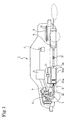
- Figs. 1 and 2 show a configuration of an exhaust gas purifying system 1 of this embodiment.
- a continuously regenerating type DPF 3 is set in an exhaust passage (exhaust pipe) 2 connected to an exhaust manifold of a diesel engine E.
- the continuously regenerating type DPF 3 is constituted of the oxidation catalyst 3Aa at the upstream side and the catalyst-provided filter 3Ab at the downstream side.
- a honeycomb structure of porous ceramic and the like supports an oxidation catalyst such as platinum (Pt), which forms the oxidation catalyst 3Aa.
- This catalyst-provided filter 3Ab is formed by a monolith honeycomb wall flow type filter constituted by alternately sealing the inlet and outlet of a porous ceramic honeycomb channel. Catalysts such as platinum and cerium oxide are supported in this filter portion.
- the PM (particulate matter) in the exhaust gas G is collected (trapped) by a porous ceramic wall.
- An exhaust throttling valve (exhaust brake) 31 for performing the exhaust throttling is set to the exhaust passage 2 at the upstream side of the continuously regenerating type DPF 3.
- a differential pressure sensor 21 is set in a conduction pipe connected to the front and the rear of the continuously regenerating type DPF 3, to estimate the quantity of the PM accumulated on the catalyst-provided filter 3Ab.
- a DPF inlet exhaust gas temperature sensor 22 is set to the upstream side of the continuously regenerating type DPF 3, for regeneration control of the catalyst-provided filter 3Ab.
- Output values of these sensors are input to the controller (electronic control box: ECU: Engine Control Unit) 5.
- the controller 5 performs general control of operations of an engine E and the control of the catalyst-provided filter 3Ab.
- a fuel injection valve 15, an exhaust throttling valve 31, and an intake valve 11, which is set to an intake passage 6 to adjust an air intake to an air-intake manifold, of the engine E are controlled by a control signal output from the controller 5.
- the following information is input to the controller 5 to operate the engine: on/off of a PTO switch, on/off of a neutral switch, vehicle speed, cooling-water temperature, engine speed, and designated injection quantity (Q).
- the fuel injection valve 15 is connected to a common rail (not illustrated) for temporarily storing high-pressure fuel boosted by a fuel pump (not illustrated).
- the intake air A flows into a combustion chamber 14 of a cylinder 13 after adjusting the quantity thereof is adjusted in the intake valve 11 via the compressor 17a of a turbocharger 17 and an intercooler 12 in an intake passage 6.
- the fuel injection valve 15 is set to the combustion chamber 14.
- the fuel injection from the fuel injection valve 15 causes the fuel and the intake air A to be mixed.
- the mixed gas is spontaneously ignited and burned, due to the compression by a piston 18, and the exhaust gas G is generated.
- the exhaust gas G passes through the exhaust throttling valve 31 via the turbine 17b of the turbocharger 17 of the exhaust passage and enters the continuously regenerating type DPF 3.
- the exhaust gas G becomes purified exhaust gas Gc in the continuously regenerating type DPF 3. This exhaust gas Gc is discharged to the atmospheric air via a muffler 8.
- the controller 5 provided with a regeneration control means P1 comprises of a fuel injection control means P11 and an exhaust throttling control means 12, as shown in Fig. 3, to regenerate the continuously regenerating type DPF 3.
- the regeneration control means P1 further comprises a regeneration start judgment means P21, an exhaust gas temperature detection means P22, a first regeneration control means P23, a second regeneration control P24, a third regeneration control P25, and regeneration end judgment means P26.
- the exhaust gas temperature detection means P22 judges a region in which an exhaust gas temperature Tg exists, which is detected by the DPF inlet exhaust gas temperature sensor 22. In other words, the means P22 judges whether the exhaust gas temperature Tg is equal to a predetermined first temperature region or lower, that is, a predetermined first temperature Tg1, whether the exhaust gas temperature Tg is within a predetermined second temperature region, that is, higher than the predetermined first temperature Tg1 and equal to a predetermined second temperature Tg2 or lower, whether the exhaust gas temperature Tg is within a predetermined third temperature region, that is, higher than the predetermined second temperature Tg2 and equal to or lower than a predetermined third temperature Tg3, or whether the exhaust gas temperature Tg is within a fourth temperature region, that is, higher than the predetermined third temperature Tg3.
- the predetermined first temperature Tg1 slightly differs, depending on an engine, this temperature is extremely low at approx. 150°C with an oxidation catalyst at an active temperature or lower.
- the predetermined second temperature Tg2 slightly differs depending on an engine, and is the low temperature of approx. 200°C at which an oxidation catalyst becomes an active temperature or lower.
- the predetermined third temperature Tg3 slightly differs depending on an engine, and is the comparatively high temperature of approx. 350°C at which an oxidation catalyst becomes an active temperature or higher.
- the first temperature region Z1 is a temperature region with an extremely low exhaust gas temperature, in which it is difficult to raise the temperature of exhaust gas up to an active temperature or higher unless the oxidation catalyst 3Aa has a temperature equal to or lower than an active temperature and first regeneration control is performed.
- the second temperature region Z2 is a temperature region in which an exhaust gas temperature is low, the oxidation catalyst 3Aa has an active temperature or lower and it is possible to raise the temperature of exhaust gas up to the active temperature or higher through second regeneration control.
- the third temperature region Z3 is a temperature region, in which an exhaust gas temperature is set so that the oxidation catalyst 3a has an active temperature or lower. However, it is a temperature region, in which a DPF can be regenerated through third regeneration control by easily raising an exhaust gas temperature up to the active temperature or higher.
- the fourth temperature region Z4 is a temperature region, in which an exhaust gas temperature is set so that the oxidation catalyst 3Aa has an active temperature or higher, and the PM is burned and removed with no regeneration control.
- the exhaust gas temperature detection means P22 As described below. That is, instead of detecting the exhaust gas temperature Tg by the DPF inlet exhaust gas temperature sensor 22, a relation between engine speed Ne, load Q, and exhaust gas temperature Tg is previously examined as shown in Fig. 6. Based on the engine speed Ne and the load Q, a relation between first temperature region (very low temperature region) Z1, second temperature region (low temperature region) Z2, third temperature region (middle temperature region) Z3, and fourth temperature region (high temperature region) Z4 of the exhaust gas temperature Tg is input to the controller 5 as map data.
- the exhaust gas temperature detection means P22 is included by referring to the map data for these temperature regions, based on the engine speed Ne detected by an engine speed sensor and the load Q detected by a load sensor.
- the regeneration control means P1 is constituted so that it is controlled by the exhaust gas temperature detection means P22 in the regeneration of the continuously regenerating type DPF 3 as follows.
- the first regeneration control means P23 performs first exhaust gas temperature raising control, by the multistage delay injection using the fuel injection control means P11 and by the exhaust throttling using the exhaust throttling control means P12.
- the second regeneration control means P24 performs second exhaust gas temperature raising control by the multistage delay injection using the fuel injection control means P11.
- the third regeneration control means P24 performs third exhaust gas temperature raising control by post injection using the fuel injection control means P11.
- the regeneration control means P1 performs regeneration control along the control flow shown in Fig. 4. First, when the regeneration control and an engine start together simultaneously, it is judged in the step S11 whether or not the regeneration is started. This judgment is performed based on whether or not the differential pressure ⁇ P of the differential pressure sensor 21 exceeds a predetermined judgment value ⁇ P0. It is also allowed to perform the judgment of regeneration start by comparing the accumulated quantity of the PM obtained by accumulating the accumulated quantity of the PM, which is calculated on the basis of an operation state of an engine, with a predetermined judgment value.
- step S11 When the differential pressure ⁇ P does not exceed the predetermined judgment value ⁇ P0 as a result of the judgment of the regeneration start in the step S11, that is, in the case of not regeneration start, the step S12 is started. Then, the normal operation control is performed for a predetermined time (time relating to time interval for judgment of the regeneration start) and then, step S11 is restarted.
- the forcible fuel injection and the like for regeneration is not performed but an engine is controlled by the fuel injection depended on the required engine speed and the load, the EGR control, the intake throttling, and the exhaust throttling and the like.
- the step S13 is started. In the step S13, an exhaust gas temperature is judged.
- the step S14 is started to perform the first regeneration control.
- the first regeneration control performs the first exhaust gas temperature raising control for performing the intake throttling for closing the exhaust throttling valve 31 by the exhaust throttling control means P12 together with excessively delay and the multistage injection by the fuel injection control means P11. This control raises the temperature of exhaust gas so that a temperature and an environment suitable for oxidation and removal of the PM are obtained. Moreover, the control oxidizes and removes the PM collected in the continuously regenerating type DPF 3.
- the excessively delay multistage injection is the fuel injection when excessively delaying (retarding) the timing of the main injection of the fuel injection of the engine E. As shown in Fig. 5, this fuel injection is performed by the multistage injection of the pilot-injection and the main injection.
- the multistage pilot-injection having a small injection quantity or injection period delay at the front stage of the main injection for example, excessively delay of the main injection is realized and the multistage delay injection of twice of pilot-injection and once of main injection shown in Fig. 5 is performed.
- the multistage injection having more number stages is more preferable.
- the pressure of the exhaust manifold at the outlet of an engine is raised.
- the exhaust pressure is set to 70 kPa or more by using the exhaust throttling.
- the temperature of the exhaust gas is raised and HC is supplied to the exhaust passage 2 at one stage or several stages.
- the PM collected in the continuously regenerating type DPF 3 is burned and removed.
- This control is performed by the regeneration end judgment means 26 until the end of regeneration is judged.
- the end of regeneration is judged depending on whether or not a predetermined time elapses or whether or not the differential pressure ⁇ P becomes equal to a predetermined judgment value ⁇ P1 or less.
- the step S11 is restarted.
- the exhaust gas temperature judgment is performed in the step S14.
- the exhaust gas temperature Tg is equal to the predetermined second temperature Tg2 or lower and is included in the second temperature region (low temperature region) Z2 as a result of the judgment of the exhaust gas temperature region in this step S14, the step S15 is started to perform the second regeneration control.
- the second regeneration control does not perform intake throttling by the exhaust throttling control means P12 but it performs the second exhaust gas temperature raising control by the fuel injection control means P11.
- This control performs the excessively delay multistage injection obtained by excessively delaying (retarding) the timing of the main injection of the fuel injection of the engine E.
- the retard value becomes smaller than the case of the first exhaust gas temperature raising control.
- the exhaust gas temperature judgment in the step S15 is performed.
- the exhaust gas temperature Tg is equal to the predetermined third temperature Tg3 or lower and is included in the third temperature region (middle temperature region) Z3 as a result of the judgment of the exhaust gas temperature region in this step S15, the step S15 is started to perform the third regeneration control.
- the third regeneration control does not perform the exhaust throttling by using the exhaust throttling control means P12 but it performs the third exhaust gas temperature raising control by the fuel injection control means P11.
- This control performs the post-injection in the fuel injection of the engine E.
- the exhaust gas temperature at the inlet of the catalyst-provided filter 3Ab is raised so that a temperature and an environment suitable for the oxidation and removal of the PM are realized. Thereby, the PM collected in the continuously regenerating type DPF 3 is oxidized and removed.
- the PM is burned and removed without performing the control for raising an exhaust gas temperature. Therefore, the normal operation control same as the case of the step S12 is performed in the step S16. In this case, the PM is burned and removed. Therefore, not regeneration start is judged as a result of the judgment of regeneration start in the step S11 and the step S16 is not started.
- these first to third regeneration controls raise the temperature of the exhaust gas and supply HC to the exhaust passage 2 by using the first to third exhaust gas temperature raising controls at one stage or several stages to burn and remove the PM collected in the continuously regenerating type DPF 3. These controls are performed until the end of regeneration is judged by the regeneration end judgment means 26. The end of regeneration is judged depending on whether or not a predetermined time elapses or whether or not the differential pressure ⁇ P becomes equal to the predetermined judgment value ⁇ P1 or lower. Then, when the end of regeneration is judged, the step S11 is restarted.
- the step S11 is restarted by passing through any route of steps S11 to S12 and steps S11 to S19 and these operations are repeated until an interruption of the step S20 by an engine key off occurs. Moreover, the end operation such as storage of the state when the interruption occurs is performed in the step S21 due to occurrence of the interruption to complete the control flow.
- the throttling quantity of the exhaust throttling valve 31 is fixed when the operation region of an engine is in an idling state Zi and the throttling quantity of the exhaust throttling valve 31 is made variable to perform the exhaust gas temperature raising control when the operation region of the engine is not in the idling state Zi.
- the throttling quantity of the exhaust throttling valve 31 is fixed to the maximum throttling quantity to realize the minimum quantity of the exhaust gas. Thereby, it is possible to extremely raise the exhaust gas temperature and lower a tail pipe outlet temperature due to reduction of the exhaust gas quantity.
- the temperature inside the cylinder becomes higher in the next compression stroke and combustion stroke.
- a high temperature is realized even through the delay injection remarkably delayed. Therefore, it is possible to obtain the secure ignition and shift to the securer combustion.
- the second-stage pilot-injection in which an injection quantity is further increased is performed when the combustion of the fuel injected at the first stage is activated.
- the fuel at the second-stage injection is a period in which a piston at the later stage of the expansion stroke is further lowered, ignition occurs and heat is generated by the first-stage stable flame even in a low pressure state. Therefore, it is possible to make the flame larger inside the cylinder and the temperature inside the cylinder further rises. However, this combustion does not contribute to occurrence of the torque but it contributes to a rise of the temperature of the exhaust gas.
- the third-stage main injection is performed when the combustion of the fuel of the second-stage injection is activated.
- the third-stage injection generates a secure main combustion flame by increasing the injection quantity further and performing the large main injection of a combustion flame. Thereby, a flame can be propagated up to a lean mixture, it is possible to prevent white smoke and misfire from generating. Therefore, it is possible to efficiently greatly raise an exhaust gas temperature.
- the main injection fuel burned nearby the period in which the exhaust valve opens extremely contributes to a rise of the exhaust gas temperature but it does not contribute to occurrence of a torque.
- the inlet temperature of the oxidation catalyst 3Aa of the continuously regenerating type DPF 3 stepwise rises as the fuel injection is stepwise performed.
- the exhaust gas temperature is raised in accordance with the increase of the load and the injected fuel quantity by using the exhaust throttling together. Moreover, because the tail pipe exit temperature is lowered due to reduction of the exhaust gas quantity, it is possible to cope with to a thermal harm.
- the exhaust gas purifying system 1 having the above configuration, it is possible to perform the following control when the differential pressure of the differential pressure sensor 21 rises and exceeds a set value and the quantity of PM accumulated in the catalyst-provided filter 3Ab of the continuously regenerating type DPF 3 must be regenerated.
- the exhaust gas temperature Tg is equal to or lower than the predetermined first temperature Tg1, that is, when the exhaust gas temperature Tg is very low like the case of the first temperature region Z1 in which an engine is operated at a low load and low engine speed such as the case of idling, it is possible to perform the first regeneration control in accordance with multistage delay injection using exhaust throttling together.
- the second temperature region Z2 in which the engine operation condition does not easily reach the exhaust gas temperature necessary for the oxidation of PM and the regeneration of the DPF, it is possible to perform the second regeneration control in accordance with the multistage delay injection not using the exhaust throttling control together.
- the exhaust gas remaining in the intake stroke can be increased in the quantity and raised in the temperature in accordance with the raise of the engine exhaust pressure by performing the exhaust throttling together with the multistage delay injection.
- the exhaust gas remaining in the intake stroke can be increased in the quantity and raised in the temperature in accordance with the raise of the engine exhaust pressure by performing the exhaust throttling together with the multistage delay injection.
- the first regeneration control using the exhaust throttling together and the second regeneration control not using the exhaust throttling together are separately used depending on whether or not the exhaust gas temperature Tg exceeds the predetermined first temperature Tg1, it is possible to reduce an exhaust pressure rise period and prevent fuel consumption from deteriorating.
- the multistage delay injection control and the post injection control are separately used depending on whether or not the exhaust gas temperature Tg exceeds the predetermined second temperature Tg2, it is possible to prevent fuel consumption from deteriorating.
- the continuously regenerating type DPF 3 having the filter 3Ab made to support a catalyst and the oxidation catalyst 3Aa on the catalyst-provided filter 3Ab is described above as the example.
- the present invention can be also applied to a DPF which is not the continuously regenerating type using only a filter, a continuously regenerating type DPF making a filter support a catalyst, and a continuously regenerating type DPF having an oxidation catalyst at the upstream side of a filter in addition to the continuously regenerating type DPF 3.
Landscapes
- Engineering & Computer Science (AREA)
- Chemical & Material Sciences (AREA)
- Combustion & Propulsion (AREA)
- Mechanical Engineering (AREA)
- General Engineering & Computer Science (AREA)
- Chemical Kinetics & Catalysis (AREA)
- Processes For Solid Components From Exhaust (AREA)
- Control Of Throttle Valves Provided In The Intake System Or In The Exhaust System (AREA)
- Electrical Control Of Air Or Fuel Supplied To Internal-Combustion Engine (AREA)
Applications Claiming Priority (2)
| Application Number | Priority Date | Filing Date | Title |
|---|---|---|---|
| JP2003311646A JP4333289B2 (ja) | 2003-09-03 | 2003-09-03 | 排気ガス浄化システム |
| JP2003311646 | 2003-09-03 |
Publications (3)
| Publication Number | Publication Date |
|---|---|
| EP1512860A2 true EP1512860A2 (fr) | 2005-03-09 |
| EP1512860A3 EP1512860A3 (fr) | 2006-03-29 |
| EP1512860B1 EP1512860B1 (fr) | 2012-06-06 |
Family
ID=34131845
Family Applications (1)
| Application Number | Title | Priority Date | Filing Date |
|---|---|---|---|
| EP04103973A Expired - Lifetime EP1512860B1 (fr) | 2003-09-03 | 2004-08-19 | Système de purification de gaz d'échappement |
Country Status (4)
| Country | Link |
|---|---|
| US (1) | US6966179B2 (fr) |
| EP (1) | EP1512860B1 (fr) |
| JP (1) | JP4333289B2 (fr) |
| CN (1) | CN100572768C (fr) |
Cited By (16)
| Publication number | Priority date | Publication date | Assignee | Title |
|---|---|---|---|---|
| US7027845B2 (en) | 2001-10-19 | 2006-04-11 | Ohashi Technica, Inc. | Hinge device and cell phone using the hinge device |
| WO2006109820A1 (fr) * | 2005-04-08 | 2006-10-19 | Toyota Jidosha Kabushiki Kaisha | Purificateur de gaz d'echappement pour moteur a combustion interne |
| WO2006123761A1 (fr) * | 2005-05-18 | 2006-11-23 | Toyota Jidosha Kabushiki Kaisha | Systeme de purification des gaz d'echappement destine a un moteur a combustion interne |
| WO2006136431A1 (fr) * | 2005-06-24 | 2006-12-28 | Emitec Gesellschaft Für Emissionstechnologie Mbh | Procede permettant de faire fonctionner un piege a particules, et dispositif pour la mise en oeuvre de ce procede |
| EP1582721A3 (fr) * | 2004-03-31 | 2007-02-28 | Isuzu Motors Limited | Méthode de commande d'un système de purification des gaz d'échappement et système de purification des gaz d'échappement |
| WO2008036010A1 (fr) * | 2006-09-19 | 2008-03-27 | Industriell Plåtproduktion Ab | Système pour gaz d'échappement |
| WO2008142549A1 (fr) * | 2007-05-23 | 2008-11-27 | Toyota Jidosha Kabushiki Kaisha | Procédé et appareil de commande de moteur à combustion interne |
| DE102008036046A1 (de) | 2008-08-01 | 2010-02-18 | Bayerische Motoren Werke Aktiengesellschaft | Abgasanlage für eine Brennkraftmaschine |
| US7877985B2 (en) | 2005-05-18 | 2011-02-01 | Toyota Jidosha Kabushiki Kaisha | Exhaust gas purification system for internal combustion engine |
| WO2011078981A1 (fr) * | 2009-12-22 | 2011-06-30 | Perkins Engines Company Limited | Commande de la pression de la rampe commune pendant la régénération continue d'un filtre à particules diesel catalysé (fpd) |
| GB2501923A (en) * | 2012-05-10 | 2013-11-13 | Gm Global Tech Operations Inc | Method of controlling an internal combustion engine |
| EP2711514A4 (fr) * | 2011-05-19 | 2014-10-22 | Hino Motors Ltd | Procédé permettant de remplacer manuellement un filtre à particules |
| EP1998015A4 (fr) * | 2006-03-17 | 2015-04-22 | Isuzu Motors Ltd | Procede de commande du systeme de purification des gaz d'echappement et systeme de purification des gaz d'echappement |
| EP2107230A4 (fr) * | 2007-01-25 | 2015-05-06 | Isuzu Motors Ltd | Procédé de commande d'un système de purification d'émission de gaz d'échappement et système de purification d'émission de gaz d'échappement |
| EP2722514A4 (fr) * | 2011-06-16 | 2016-02-17 | Yanmar Co Ltd | Dispositif de moteur thermique |
| EP1905992B1 (fr) * | 2005-07-15 | 2018-08-08 | Isuzu Motors Limited | Procédé de commande du système de purification du gaz d échappement, et système de purification du gaz d échappement |
Families Citing this family (56)
| Publication number | Priority date | Publication date | Assignee | Title |
|---|---|---|---|---|
| JP4345359B2 (ja) * | 2003-05-28 | 2009-10-14 | いすゞ自動車株式会社 | 排気ガス浄化システム |
| FR2862096B1 (fr) * | 2003-11-07 | 2006-02-17 | Peugeot Citroen Automobiles Sa | Systeme d'aide a la regeneration de moyens de depollution integres dans une ligne d'echappement d'un moteur de vehicule |
| FR2862100B1 (fr) * | 2003-11-07 | 2008-04-04 | Peugeot Citroen Automobiles Sa | Systeme d'aide a la regeneration de moyens de depollution integres dans une ligne d'echappement d'un vehicule |
| FR2862103B1 (fr) * | 2003-11-07 | 2006-02-17 | Peugeot Citroen Automobiles Sa | Systeme d'aide a la regeneration de moyens de depollution integres dans une ligne d'echapement d'un moteur diesel de vehicule automobile |
| JP2005282533A (ja) * | 2004-03-30 | 2005-10-13 | Isuzu Motors Ltd | ディーゼルエンジンの排気ガス後処理装置 |
| JP4161931B2 (ja) * | 2004-04-07 | 2008-10-08 | いすゞ自動車株式会社 | 排気ガス浄化システムの制御方法及び排気ガス浄化システム |
| JP2005299457A (ja) * | 2004-04-09 | 2005-10-27 | Isuzu Motors Ltd | エンジンの排気ガス絞り弁 |
| WO2005116410A1 (fr) * | 2004-05-28 | 2005-12-08 | Hino Motors, Ltd. | Épurateur de gaz d'échappement |
| JP4193801B2 (ja) * | 2005-01-13 | 2008-12-10 | トヨタ自動車株式会社 | 内燃機関の排気浄化システム |
| US7340888B2 (en) * | 2005-04-26 | 2008-03-11 | Donaldson Company, Inc. | Diesel particulate matter reduction system |
| US7343735B2 (en) * | 2005-05-02 | 2008-03-18 | Cummins, Inc. | Apparatus and method for regenerating an exhaust gas aftertreatment component of an internal combustion engine |
| JP3938188B2 (ja) * | 2005-05-17 | 2007-06-27 | いすゞ自動車株式会社 | 排気ガス浄化システムの制御方法及び排気ガス浄化システム |
| JP2007113395A (ja) * | 2005-10-17 | 2007-05-10 | Aisan Ind Co Ltd | 排気バルブ |
| JP3992057B2 (ja) | 2005-10-25 | 2007-10-17 | いすゞ自動車株式会社 | 排気ガス浄化システムの制御方法及び排気ガス浄化システム |
| US8119075B2 (en) | 2005-11-10 | 2012-02-21 | Basf Corporation | Diesel particulate filters having ultra-thin catalyzed oxidation coatings |
| JP4017010B2 (ja) * | 2006-02-01 | 2007-12-05 | いすゞ自動車株式会社 | 排気ガス浄化システムの制御方法及び排気ガス浄化システム |
| GB0603898D0 (en) * | 2006-02-28 | 2006-04-05 | Johnson Matthey Plc | Exhaust system comprising catalysed soot filter |
| US7862640B2 (en) | 2006-03-21 | 2011-01-04 | Donaldson Company, Inc. | Low temperature diesel particulate matter reduction system |
| US8091344B2 (en) * | 2006-06-13 | 2012-01-10 | Cummins Inc. | System for modifying exhaust gas flow through an aftertreatment device |
| JP4055808B2 (ja) * | 2006-06-13 | 2008-03-05 | いすゞ自動車株式会社 | 排気ガス浄化システムの制御方法及び排気ガス浄化システム |
| JP4049193B2 (ja) * | 2006-06-13 | 2008-02-20 | いすゞ自動車株式会社 | 排気ガス浄化システムの制御方法及び排気ガス浄化システム |
| JP4304527B2 (ja) | 2006-07-03 | 2009-07-29 | トヨタ自動車株式会社 | 内燃機関の排気浄化装置 |
| US7685814B2 (en) * | 2006-07-12 | 2010-03-30 | Cummins Filtration, Inc. | Systems, apparatuses, and methods of determining plugging or deplugging of a diesel oxidation catalyst device |
| ES2552011T3 (es) * | 2007-02-21 | 2015-11-25 | Volvo Lastvagnar Ab | Sistema y procedimiento de post-tratamiento de los gases del escape |
| US7684924B2 (en) * | 2007-07-02 | 2010-03-23 | Gm Global Technology Operations, Inc. | Thermal detection and protection of vehicle hardware |
| US7861515B2 (en) * | 2007-07-13 | 2011-01-04 | Ford Global Technologies, Llc | Monitoring of exhaust gas oxygen sensor performance |
| US20090183499A1 (en) * | 2008-01-17 | 2009-07-23 | Basf Catalysts Llc | Apparatus and control method for avoiding shock in diesel filters |
| US8375705B2 (en) * | 2008-05-30 | 2013-02-19 | Caterpillar Inc. | Exhaust system implementing low-temperature regeneration strategy |
| DE102008041874A1 (de) * | 2008-09-08 | 2010-03-11 | Robert Bosch Gmbh | Vorrichtung und Verfahren zum Betreiben einer Brennkraftmaschine, Computerprogramm, Computerprogrammprodukt |
| JP5332575B2 (ja) * | 2008-12-10 | 2013-11-06 | 日産自動車株式会社 | 内燃機関の排気浄化装置 |
| US9371754B2 (en) * | 2009-03-12 | 2016-06-21 | Caterpillar Inc. | Diesel particulate filter regeneration control and method |
| KR101076156B1 (ko) * | 2009-07-20 | 2011-10-21 | 기아자동차주식회사 | 디젤 매연여과장치의 제어방법 |
| US20110036331A1 (en) * | 2009-08-12 | 2011-02-17 | Milton Russell Pocha | Supercharger system for two-stroke engines |
| US8875494B2 (en) * | 2009-09-29 | 2014-11-04 | Ford Global Technologies, Llc | Fuel control for spark ignited engine having a particulate filter system |
| US8341951B2 (en) * | 2009-11-04 | 2013-01-01 | GM Global Technology Operations LLC | Vehicle exhaust heat recovery with multiple coolant heating modes and method of managing exhaust heat recovery |
| GB0922194D0 (en) | 2009-12-21 | 2010-02-03 | Johnson Matthey Plc | Improvements in emission control |
| US8806857B2 (en) * | 2010-01-20 | 2014-08-19 | Mark D. Shaw | Device and method for removing carbon dioxide from motor vehicle exhaust |
| JP5404460B2 (ja) * | 2010-02-09 | 2014-01-29 | 三菱重工業株式会社 | エンジンの排気浄化装置及び方法、並びにエンジンの排気浄化装置に係るフィルタの再生システム |
| JP5440384B2 (ja) * | 2010-05-25 | 2014-03-12 | いすゞ自動車株式会社 | 排ガス浄化システム |
| JP5533260B2 (ja) * | 2010-05-25 | 2014-06-25 | いすゞ自動車株式会社 | Dpfシステム |
| SE535930C2 (sv) * | 2010-06-21 | 2013-02-26 | Scania Cv Ab | Förfarande och anordning för undvikande av överhettning hos en doseringsenhet vid ett SCR-system |
| SE535931C2 (sv) * | 2010-06-21 | 2013-02-26 | Scania Cv Ab | Förfarande och anordning för undvikande av överhettning hos en doseringsenhet vid ett HC-doseringssystem |
| KR20120011563A (ko) * | 2010-07-29 | 2012-02-08 | 현대자동차주식회사 | 배기가스 후처리 시스템 및 이 제어방법 |
| SE536026C2 (sv) * | 2010-08-31 | 2013-04-09 | Scania Cv Ab | Förfarande och system för avgasrening |
| US8857152B2 (en) * | 2010-12-21 | 2014-10-14 | GM Global Technology Operations LLC | System and method for unloading hydrocarbon emissions from an exhaust after-treatment device |
| US8756912B2 (en) * | 2012-03-16 | 2014-06-24 | GM Global Technology Operations LLC | Method of setting a particulate filter regeneration setpoint based on exhaust flow mass |
| JP6011224B2 (ja) * | 2012-10-09 | 2016-10-19 | いすゞ自動車株式会社 | 排気ガス浄化システム及び排気ガス浄化方法 |
| JP6094736B2 (ja) * | 2012-12-28 | 2017-03-15 | 三菱自動車工業株式会社 | 車両の内燃機関 |
| US9739223B2 (en) * | 2015-11-18 | 2017-08-22 | Ford Global Technologies, Llc | System and method for bypassing a particulate filter |
| CN107429615A (zh) * | 2017-02-06 | 2017-12-01 | 株式会社小松制作所 | 排气净化装置及作业车辆 |
| TWI647405B (zh) * | 2017-08-30 | 2019-01-11 | 國家中山科學研究院 | Wisdom gas filter device control system judgment method |
| JP7132798B2 (ja) * | 2018-08-31 | 2022-09-07 | 三菱重工エンジン&ターボチャージャ株式会社 | Dpf再生制御装置及びdpf再生制御方法 |
| JP7178219B2 (ja) * | 2018-09-10 | 2022-11-25 | 三菱重工エンジン&ターボチャージャ株式会社 | 制御装置、排ガス浄化システムおよびエンジンの制御方法 |
| CN112377313A (zh) * | 2020-11-09 | 2021-02-19 | 一汽解放汽车有限公司 | 一种电控排气管理阀及车辆 |
| CN113339150B (zh) * | 2021-07-22 | 2023-03-17 | 中国第一汽车股份有限公司 | 一种汽油机颗粒捕集器再生控制方法 |
| CN114033532B (zh) * | 2021-11-08 | 2022-12-30 | 凯龙高科技股份有限公司 | Dpf主动再生周期确定方法、装置、电子设备及存储介质 |
Family Cites Families (14)
| Publication number | Priority date | Publication date | Assignee | Title |
|---|---|---|---|---|
| JPS58158348A (ja) * | 1982-03-15 | 1983-09-20 | Toyota Motor Corp | ディーゼルエンジンの排気微粒子浄化制御装置 |
| JPH0621543B2 (ja) | 1987-02-16 | 1994-03-23 | 日野自動車工業株式会社 | 排気ガス用フイルタの再生装置 |
| JP3024780B2 (ja) * | 1990-07-25 | 2000-03-21 | 日産ディーゼル工業株式会社 | ディーゼルエンジンの排気浄化装置 |
| JPH0949422A (ja) * | 1995-08-09 | 1997-02-18 | Denso Corp | 内燃機関の排出ガス浄化装置 |
| CN1077212C (zh) * | 1996-07-02 | 2002-01-02 | 三菱自动车工业株式会社 | 缸内喷射内燃机用废气加热系统 |
| DE19715921A1 (de) * | 1997-04-16 | 1998-10-22 | Schatz Thermo Gastech Gmbh | Verfahren und Vorrichtung zur Schadstoffminderung |
| DE19957715C2 (de) * | 1998-12-01 | 2002-01-17 | Toyota Motor Co Ltd | Abgasausstoß-Steuerungsvorrichtung für eine Brennkraftmaschine |
| DE19923299A1 (de) * | 1999-05-21 | 2000-11-23 | Bosch Gmbh Robert | Verfahren und Vorrichtung zur Steuerung einer Brennkraftmaschine |
| JP3633401B2 (ja) * | 1999-10-26 | 2005-03-30 | トヨタ自動車株式会社 | 内燃機関の排気昇温装置 |
| WO2002066813A1 (fr) * | 2001-02-20 | 2002-08-29 | Isuzu Motors Limited | Procede de commande d'injection de carburant pour moteur diesel et procede de commande de regeneration de gaz d'echappement apres un dispositif de traitement |
| EP1365137B9 (fr) * | 2001-02-26 | 2006-07-12 | Mitsubishi Jidosha Kogyo Kabushiki Kaisha | Purificateur de gaz d'echappement pour moteurs thermiques |
| JP4161546B2 (ja) * | 2001-06-26 | 2008-10-08 | いすゞ自動車株式会社 | 連続再生型ディーゼルパティキュレートフィルタ装置の再生制御方法 |
| DE60238235D1 (de) * | 2001-09-07 | 2010-12-23 | Mitsubishi Motors Corp | Vorrichtung zur Abgasemissionssteuerung eines Motors |
| JP4345359B2 (ja) * | 2003-05-28 | 2009-10-14 | いすゞ自動車株式会社 | 排気ガス浄化システム |
-
2003
- 2003-09-03 JP JP2003311646A patent/JP4333289B2/ja not_active Expired - Fee Related
-
2004
- 2004-08-19 EP EP04103973A patent/EP1512860B1/fr not_active Expired - Lifetime
- 2004-08-30 US US10/928,699 patent/US6966179B2/en not_active Expired - Lifetime
- 2004-08-31 CN CNB2004100683936A patent/CN100572768C/zh not_active Expired - Lifetime
Cited By (26)
| Publication number | Priority date | Publication date | Assignee | Title |
|---|---|---|---|---|
| US7027845B2 (en) | 2001-10-19 | 2006-04-11 | Ohashi Technica, Inc. | Hinge device and cell phone using the hinge device |
| EP1582721A3 (fr) * | 2004-03-31 | 2007-02-28 | Isuzu Motors Limited | Méthode de commande d'un système de purification des gaz d'échappement et système de purification des gaz d'échappement |
| US7721534B2 (en) | 2004-03-31 | 2010-05-25 | Isuzu Motors Limited | Control method for an exhaust gas purification system and an exhaust gas purification system |
| WO2006109820A1 (fr) * | 2005-04-08 | 2006-10-19 | Toyota Jidosha Kabushiki Kaisha | Purificateur de gaz d'echappement pour moteur a combustion interne |
| US7320214B2 (en) | 2005-04-08 | 2008-01-22 | Toyota Jidosha Kabushiki Kaisha | Exhaust gas purifier for internal combustion engine |
| WO2006123761A1 (fr) * | 2005-05-18 | 2006-11-23 | Toyota Jidosha Kabushiki Kaisha | Systeme de purification des gaz d'echappement destine a un moteur a combustion interne |
| US7877985B2 (en) | 2005-05-18 | 2011-02-01 | Toyota Jidosha Kabushiki Kaisha | Exhaust gas purification system for internal combustion engine |
| CN101248258B (zh) * | 2005-06-24 | 2010-12-22 | 排放技术有限公司 | 用于操作颗粒陷阱的方法 |
| WO2006136431A1 (fr) * | 2005-06-24 | 2006-12-28 | Emitec Gesellschaft Für Emissionstechnologie Mbh | Procede permettant de faire fonctionner un piege a particules, et dispositif pour la mise en oeuvre de ce procede |
| KR100918604B1 (ko) * | 2005-06-24 | 2009-09-25 | 에미텍 게젤샤프트 퓌어 에미시온스테크놀로기 엠베하 | 미립자 포획부를 작동시키는 방법 및 이 방법을 실행시키는장치 |
| EP1905992B1 (fr) * | 2005-07-15 | 2018-08-08 | Isuzu Motors Limited | Procédé de commande du système de purification du gaz d échappement, et système de purification du gaz d échappement |
| EP1998015A4 (fr) * | 2006-03-17 | 2015-04-22 | Isuzu Motors Ltd | Procede de commande du systeme de purification des gaz d'echappement et systeme de purification des gaz d'echappement |
| WO2008036010A1 (fr) * | 2006-09-19 | 2008-03-27 | Industriell Plåtproduktion Ab | Système pour gaz d'échappement |
| EP2107230A4 (fr) * | 2007-01-25 | 2015-05-06 | Isuzu Motors Ltd | Procédé de commande d'un système de purification d'émission de gaz d'échappement et système de purification d'émission de gaz d'échappement |
| WO2008142549A1 (fr) * | 2007-05-23 | 2008-11-27 | Toyota Jidosha Kabushiki Kaisha | Procédé et appareil de commande de moteur à combustion interne |
| US7853399B2 (en) | 2007-05-23 | 2010-12-14 | Toyota Jidosha Kabushiki Kaisha | Internal combustion engine control apparatus and method |
| DE102008036046A1 (de) | 2008-08-01 | 2010-02-18 | Bayerische Motoren Werke Aktiengesellschaft | Abgasanlage für eine Brennkraftmaschine |
| US8631642B2 (en) | 2009-12-22 | 2014-01-21 | Perkins Engines Company Limited | Regeneration assist calibration |
| EP2628925A3 (fr) * | 2009-12-22 | 2014-08-27 | Perkins Engines Company Limited | Calibrage d'assistance de régénération |
| EP2628928A3 (fr) * | 2009-12-22 | 2014-08-27 | Perkins Engines Company Limited | Calibrage d'assistance de régénération |
| US8776501B2 (en) | 2009-12-22 | 2014-07-15 | Perkins Engines Company Limited | Regeneration assist calibration |
| WO2011078981A1 (fr) * | 2009-12-22 | 2011-06-30 | Perkins Engines Company Limited | Commande de la pression de la rampe commune pendant la régénération continue d'un filtre à particules diesel catalysé (fpd) |
| EP2711514A4 (fr) * | 2011-05-19 | 2014-10-22 | Hino Motors Ltd | Procédé permettant de remplacer manuellement un filtre à particules |
| EP2722514A4 (fr) * | 2011-06-16 | 2016-02-17 | Yanmar Co Ltd | Dispositif de moteur thermique |
| US9376996B2 (en) | 2011-06-16 | 2016-06-28 | Yanmar Co., Ltd. | Engine device |
| GB2501923A (en) * | 2012-05-10 | 2013-11-13 | Gm Global Tech Operations Inc | Method of controlling an internal combustion engine |
Also Published As
| Publication number | Publication date |
|---|---|
| JP4333289B2 (ja) | 2009-09-16 |
| JP2005076604A (ja) | 2005-03-24 |
| CN1590726A (zh) | 2005-03-09 |
| US20050044845A1 (en) | 2005-03-03 |
| EP1512860B1 (fr) | 2012-06-06 |
| EP1512860A3 (fr) | 2006-03-29 |
| CN100572768C (zh) | 2009-12-23 |
| US6966179B2 (en) | 2005-11-22 |
Similar Documents
| Publication | Publication Date | Title |
|---|---|---|
| EP1512860B1 (fr) | Système de purification de gaz d'échappement | |
| JP4345359B2 (ja) | 排気ガス浄化システム | |
| EP1445438A1 (fr) | Système de purification de gaz d'échappement | |
| JP3870815B2 (ja) | 内燃機関の排気浄化装置 | |
| CN101379274B (zh) | 废气净化系统的控制方法及废气净化系统 | |
| US7115237B2 (en) | Exhaust gas purifying method and exhaust gas purifying system | |
| JPWO2002066813A1 (ja) | ディーゼルエンジンの燃料噴射制御方法と排気ガス後処理装置の再生制御方法 | |
| JP2004162613A (ja) | 内燃機関の排気浄化装置 | |
| JP2010031833A (ja) | ディーゼルエンジンの排気浄化装置 | |
| US8549843B2 (en) | Method of controlling exhaust gas purification system and exhaust gas purification system | |
| JP3992057B2 (ja) | 排気ガス浄化システムの制御方法及び排気ガス浄化システム | |
| JP2003206722A (ja) | 内燃機関の排気浄化装置 | |
| JP4333230B2 (ja) | 内燃機関の排気浄化システム | |
| JP2003027919A (ja) | 過給機付ディーゼルエンジンの排気浄化装置 | |
| JP4107017B2 (ja) | エンジン制御装置 | |
| JP4292923B2 (ja) | 内燃機関の排気ガス浄化方法と排気ガス浄化システム | |
| EP1512849A2 (fr) | Dispositif et procédé d'épuration de gaz d'échappement | |
| JP2005163652A (ja) | 排気浄化装置 | |
| JP2004162612A (ja) | 内燃機関の排気浄化装置 | |
| JP4285162B2 (ja) | 排気ガス浄化システム | |
| JP4292861B2 (ja) | 排気ガス浄化方法及びそのシステム | |
| JP2004360480A (ja) | 排気ガス浄化方法及びそのシステム | |
| JP2007023876A (ja) | 排気ガス浄化システムの制御方法及び排気ガス浄化システム | |
| JP2022090198A (ja) | ディーゼルエンジン |
Legal Events
| Date | Code | Title | Description |
|---|---|---|---|
| PUAI | Public reference made under article 153(3) epc to a published international application that has entered the european phase |
Free format text: ORIGINAL CODE: 0009012 |
|
| AK | Designated contracting states |
Kind code of ref document: A2 Designated state(s): AT BE BG CH CY CZ DE DK EE ES FI FR GB GR HU IE IT LI LU MC NL PL PT RO SE SI SK TR |
|
| AX | Request for extension of the european patent |
Extension state: AL HR LT LV MK |
|
| PUAL | Search report despatched |
Free format text: ORIGINAL CODE: 0009013 |
|
| AK | Designated contracting states |
Kind code of ref document: A3 Designated state(s): AT BE BG CH CY CZ DE DK EE ES FI FR GB GR HU IE IT LI LU MC NL PL PT RO SE SI SK TR |
|
| AX | Request for extension of the european patent |
Extension state: AL HR LT LV MK |
|
| 17P | Request for examination filed |
Effective date: 20060624 |
|
| 17Q | First examination report despatched |
Effective date: 20061005 |
|
| AKX | Designation fees paid |
Designated state(s): DE FR GB IT |
|
| GRAP | Despatch of communication of intention to grant a patent |
Free format text: ORIGINAL CODE: EPIDOSNIGR1 |
|
| RIC1 | Information provided on ipc code assigned before grant |
Ipc: F02D 9/06 20060101ALI20111125BHEP Ipc: F02D 41/02 20060101AFI20111125BHEP Ipc: F01N 9/00 20060101ALI20111125BHEP Ipc: F01N 3/023 20060101ALI20111125BHEP Ipc: F01N 3/035 20060101ALI20111125BHEP Ipc: F02D 41/40 20060101ALI20111125BHEP |
|
| GRAS | Grant fee paid |
Free format text: ORIGINAL CODE: EPIDOSNIGR3 |
|
| GRAA | (expected) grant |
Free format text: ORIGINAL CODE: 0009210 |
|
| RIN1 | Information on inventor provided before grant (corrected) |
Inventor name: ONODERA, TAKAO Inventor name: TASHIRO, YOSHIHISA Inventor name: GABE, MASASHI Inventor name: HASEYAMA, TAKASHI Inventor name: SHIBATA, HIDETAKA Inventor name: IWASHITA, TAKURO Inventor name: IGARASHI, TAKESHI |
|
| AK | Designated contracting states |
Kind code of ref document: B1 Designated state(s): DE FR GB IT |
|
| REG | Reference to a national code |
Ref country code: GB Ref legal event code: FG4D |
|
| REG | Reference to a national code |
Ref country code: DE Ref legal event code: R096 Ref document number: 602004038042 Country of ref document: DE Effective date: 20120802 |
|
| PG25 | Lapsed in a contracting state [announced via postgrant information from national office to epo] |
Ref country code: IT Free format text: LAPSE BECAUSE OF FAILURE TO SUBMIT A TRANSLATION OF THE DESCRIPTION OR TO PAY THE FEE WITHIN THE PRESCRIBED TIME-LIMIT Effective date: 20120606 |
|
| PLBE | No opposition filed within time limit |
Free format text: ORIGINAL CODE: 0009261 |
|
| STAA | Information on the status of an ep patent application or granted ep patent |
Free format text: STATUS: NO OPPOSITION FILED WITHIN TIME LIMIT |
|
| 26N | No opposition filed |
Effective date: 20130307 |
|
| REG | Reference to a national code |
Ref country code: DE Ref legal event code: R097 Ref document number: 602004038042 Country of ref document: DE Effective date: 20130307 |
|
| REG | Reference to a national code |
Ref country code: FR Ref legal event code: PLFP Year of fee payment: 13 |
|
| PGFP | Annual fee paid to national office [announced via postgrant information from national office to epo] |
Ref country code: FR Payment date: 20160712 Year of fee payment: 13 |
|
| REG | Reference to a national code |
Ref country code: FR Ref legal event code: ST Effective date: 20180430 |
|
| PG25 | Lapsed in a contracting state [announced via postgrant information from national office to epo] |
Ref country code: FR Free format text: LAPSE BECAUSE OF NON-PAYMENT OF DUE FEES Effective date: 20170831 |
|
| PGFP | Annual fee paid to national office [announced via postgrant information from national office to epo] |
Ref country code: GB Payment date: 20210714 Year of fee payment: 18 |
|
| GBPC | Gb: european patent ceased through non-payment of renewal fee |
Effective date: 20220819 |
|
| PG25 | Lapsed in a contracting state [announced via postgrant information from national office to epo] |
Ref country code: GB Free format text: LAPSE BECAUSE OF NON-PAYMENT OF DUE FEES Effective date: 20220819 |
|
| PGFP | Annual fee paid to national office [announced via postgrant information from national office to epo] |
Ref country code: DE Payment date: 20230627 Year of fee payment: 20 |
|
| REG | Reference to a national code |
Ref country code: DE Ref legal event code: R071 Ref document number: 602004038042 Country of ref document: DE |