EP1511022A1 - Mecanisme de support de lentille, dispositif a tete optique et unite de traitement d'informations optiques - Google Patents
Mecanisme de support de lentille, dispositif a tete optique et unite de traitement d'informations optiques Download PDFInfo
- Publication number
- EP1511022A1 EP1511022A1 EP03730561A EP03730561A EP1511022A1 EP 1511022 A1 EP1511022 A1 EP 1511022A1 EP 03730561 A EP03730561 A EP 03730561A EP 03730561 A EP03730561 A EP 03730561A EP 1511022 A1 EP1511022 A1 EP 1511022A1
- Authority
- EP
- European Patent Office
- Prior art keywords
- lens
- semiconductor laser
- support mechanism
- cylindrical member
- expansion coefficient
- Prior art date
- Legal status (The legal status is an assumption and is not a legal conclusion. Google has not performed a legal analysis and makes no representation as to the accuracy of the status listed.)
- Withdrawn
Links
Images


Classifications
-
- G—PHYSICS
- G11—INFORMATION STORAGE
- G11B—INFORMATION STORAGE BASED ON RELATIVE MOVEMENT BETWEEN RECORD CARRIER AND TRANSDUCER
- G11B7/00—Recording or reproducing by optical means, e.g. recording using a thermal beam of optical radiation by modifying optical properties or the physical structure, reproducing using an optical beam at lower power by sensing optical properties; Record carriers therefor
- G11B7/12—Heads, e.g. forming of the optical beam spot or modulation of the optical beam
- G11B7/123—Integrated head arrangements, e.g. with source and detectors mounted on the same substrate
-
- G—PHYSICS
- G11—INFORMATION STORAGE
- G11B—INFORMATION STORAGE BASED ON RELATIVE MOVEMENT BETWEEN RECORD CARRIER AND TRANSDUCER
- G11B7/00—Recording or reproducing by optical means, e.g. recording using a thermal beam of optical radiation by modifying optical properties or the physical structure, reproducing using an optical beam at lower power by sensing optical properties; Record carriers therefor
- G11B7/08—Disposition or mounting of heads or light sources relatively to record carriers
-
- G—PHYSICS
- G11—INFORMATION STORAGE
- G11B—INFORMATION STORAGE BASED ON RELATIVE MOVEMENT BETWEEN RECORD CARRIER AND TRANSDUCER
- G11B7/00—Recording or reproducing by optical means, e.g. recording using a thermal beam of optical radiation by modifying optical properties or the physical structure, reproducing using an optical beam at lower power by sensing optical properties; Record carriers therefor
- G11B7/12—Heads, e.g. forming of the optical beam spot or modulation of the optical beam
- G11B7/135—Means for guiding the beam from the source to the record carrier or from the record carrier to the detector
- G11B7/1372—Lenses
- G11B7/1376—Collimator lenses
Definitions
- the present invention relates to a lens support mechanism for preventing focal length deviation or optical axis deviation due to expansion and contraction caused by a temperature change of a main part of optical members such as a lens or an optical enclosure.
- the present invention relates also to an optical head device and optical information processor using the same.
- optical memory techniques using optical disks having pit-like patterns have been applied further to digital audio disks, video disks, text file disks, and further to data files or the like.
- information is recorded and reproduced with a high accuracy and reliability into an optical disk via a finely-converged optical beam.
- An optical head device is configured by assembling optical members such as a light source, a photodetector, a half-mirror and a lens into a predetermined frame. The respective optical members must be positioned precisely for preventing deviation of the optical axis or deviation of the focal point position.
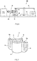
- FIG. 7 is a perspective view showing a configuration of a conventional lens support mechanism.
- a sensor lens 17 is formed by PC-integrally casting a concave lens 31 as a main part of the optical members, a lens barrel 32 formed to surround the concave lens 31, and three support arms 33, 34 and 35 extending outward from the lens barrel 32.
- vertical slits 33a and 33b are formed respectively to extend from the tops to the bottoms so that the distal end portions will be deformed resiliently with respect to the proximal end portions.
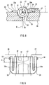
- FIG. 8 is a cross-sectional view showing a conventional lens support mechanism in an attached state.
- the center of the concave lens 31 is determined as an origin point where X-, Y- and Z-axes cross each other at right angles and the Z-axis conforms with the optical axis of the concave lens 31.
- a plane defined by the X- and Y-axes will be referred to as a first reference plane I, and a plane defined by the Y- and Z-axes will be referred to as a second reference plane II.
- a frame 18 for supporting the sensor lens 17 is formed with a first support surface 26 and a second support surface 27 both extending along the first reference plane I, and also a third support surface 28 extending along the second reference plane II.
- This frame 18 has a groove 29 in which almost a half of the cross section of a lens barrel 32 is received in a non-contact fashion.
- One side face of each of the support arm 33 and the support arm 34 is in contact with the first support surface 26 and the second support surface 27 of the frame 18.
- One side face of the support arm 35 is in contact with the third support surface 28 of the frame 18. In this manner, the sensor lens 17 is attached to the frame 18.
- the sensor lens 17 is urged, via a leaf spring 36 fixed to the frame 18 as a resilient securing means, in a composite direction between the X-axis and the Y-axis as shown with a dotted arrow in FIG. 8.
- the distal ends of the support arms 33 and 34 are firmly fixed onto the respective support surfaces 26 and 27 of the frame 18 via adhesives 37 and 38 so as not to fall off the frame 18.
- the support arms 33 and 34 are pressed resiliently via the leaf spring 36 against the support surfaces 26 and 27, and the support arm 35 is pressed resiliently against the support surface 28. In this manner, the center of the sensor lens 17 is fixed at the optical axis position.
- FIG. 9 is a schematic view for explaining operations of a conventional lens support mechanism.
- the proximal end portions of the support arms 33 and 34 are shifted along the support surfaces 26 and 27, and the support arm 35 is shifted along the support surface 28. Since the distal end portions of the support arms 33 and 34 are fixed respectively at the support surfaces 26 and 27 by means of the adhesives 37 and 38, the displacement of the proximal end portions of the support arms 33 and 34 can be accommodated by the vertical slits 33a and 33b. In this case, the optical axis of the concave lens 31 does not change in position because the thermal expansion occurs only in a radial direction from the center of the lens 31.
- the distal end portions of the support arms 33 and 34 are fixed with the adhesives 37 and 38, and the center of the concave lens 31 is separated along the optical axis direction by a distance d from the position fixed by means of the adhesives 37 and 38. Therefore, the position of the concave lens 31 will be displaced along the optical axis direction by 'a distance (d)' ⁇ 'coefficient of thermal expansion' ⁇ ' ⁇ Tm (temperature difference)' due to expansion and contraction caused by heat.
- the temperature characteristics of the entire optical pickup device can be improved further by intentionally creating a deviation in advance that can accommodate a deviation in the optical axis direction caused by expansion and contraction by heat of the other components such as a half mirror, a collimator lens and an objective lens.
- an optical head device it is required to assure an operation environment in a wide temperature range from a low temperature to a high temperature.
- temperature characteristics must be improved in order to prevent the collimator lens from defocusing with respect to the semiconductor laser.
- the optical head enclosure supporting the collimator lens expands due to temperature changes and since the stem expands in an area ranging from a laser attachment reference surface to an emission point, a displacement occurs between the emission point and the collimator lens.
- a back focus amount of the collimator lens will vary due to a change in oscillation wavelength of a laser diode and also changes in the refractive index and shape of the collimator lens.
- the lens integrated with a lens barrel has a complicated structure, and thus the production cost is increased and a further precise adjustment is required.
- an optical head device including the lens support mechanism of this lens integrated with a lens barrel and also an optical information device have problems of degradation of the temperature characteristics and high cost.
- An object of the present invention is to provide a lens support mechanism that can accommodate displacement between an emission point and a collimator lens, which is caused by thermal expansion and thermal contraction, and provides also an optical head device and an optical information processor.
- a lens support mechanism includes: a semiconductor laser for emitting a laser beam; an enclosure to which the semiconductor laser is fixed and located; a lens disposed coaxially with the laser beam emitted from the semiconductor laser; a first cylindrical member formed in a cylindrical shape so as to fix and locate the lens to the inner surface thereof; and a second cylindrical member fitted to the first cylindrical member on the side of the lens opposite to the semiconductor laser and formed so as to be fixed to the enclosure; wherein the second cylindrical member has a linear expansion coefficient substantially the same as the linear expansion coefficient of the enclosure.
- Another lens support mechanism includes: a semiconductor laser for emitting a laser beam; a support base to which the semiconductor laser is fixed and located; a lens disposed coaxially with the laser beam emitted from the semiconductor laser; and a frame member formed so as to fix and locate the lens to the inner surface thereof; wherein the frame member is made of a material having a small linear expansion coefficient so that the distance between the semiconductor laser and the lens will not change substantially due to the temperature change.
- a still further lens support mechanism includes: a semiconductor laser for emitting a laser beam; a support base to which the semiconductor laser is fixed and located; a lens disposed coaxially with the laser beam emitted from the semiconductor laser; a cylindrical frame member formed so as to fix and locate the lens to the inner surface thereof; and a plate fixed to the support base so as to fit to the frame member; wherein the plate has a linear expansion coefficient substantially the same as the linear expansion coefficient of the support base.
- An optical head device is characterized in that it includes a lens support mechanism according to the present invention, and an objective lens for converging, onto an information recording medium, the laser beam that has passed through the lens provided to the lens support mechanism.
- An optical information processor is characterized in that it includes an optical head device according to the present invention, a motor for rotating the information recording medium, a servo mechanism for controlling the position of the objective lens provided to the optical head device, on the basis of a focus error signal and a tracking error signal obtained from the optical head device; and an electric circuit for controlling the servo mechanism.
- a second cylindrical member which fits to a first cylindrical member on a side of a lens opposite to a semiconductor laser and formed so as to be fixed to the enclosure, has a linear expansion coefficient substantially the same as a linear expansion coefficient of the enclosure. Therefore, the second cylindrical member thermally expands or thermally contracts so as to accommodate the thermal expansion or thermal contraction of the enclosure. As a result, an optical axis deviation or a focal length deviation of the lens can be prevented.
- the second cylindrical member and the enclosure are made of aluminum.
- the second cylindrical member and the enclosure are made of zinc.
- the second cylindrical member is made of zinc, and the enclosure is made of magnesium.
- the second cylindrical member is made of zinc, and the enclosure is made of polyphenylene sulfide.
- a frame member formed so as to fix and locate a lens to the inner surface thereof is made of a material having a small linear expansion coefficient so that the distance between the semiconductor laser and the lens will not change substantially. Therefore, the frame member for fixing and locating the lens will not thermally expand or contract substantially due to a temperature change. As a result, occurrence of optical axis deviation or focal length deviation of the lens can be prevented.
- the frame member is made of a ceramic material.
- a plate which is fixed to a support base so as to fit to the frame member formed so as to fix and locate a lens to the inner surface thereof, has a linear expansion coefficient substantially same as the linear expansion coefficient of the support base. Therefore, the plate will thermally expand or thermally contract so as to accommodate the thermal expansion or thermal contraction of the support base. As a result, the occurrence of optical axis deviation or focal length deviation of the lens can be prevented.
- the frame member is made of a ceramic material.
- a back focus variation ⁇ fb per unit temperature of the lens satisfies substantially Relation (3) below: ⁇ fb - ⁇ z + ⁇ L + ⁇ t ⁇ 0
- ⁇ z ⁇ z
- ⁇ t ⁇ t
- ⁇ L a shift per unit temperature of a distance from a reference surface for attachment of the semiconductor laser to a position at which the lens is fixed
- ⁇ a linear expansion coefficient of the support base and the plate (unit:/K)
- ⁇ a linear expansion coefficient of a stem provided to the semiconductor laser (unit: /K)
- z a distance from a reference surface for attachment of the semiconductor laser to an emission point of the semiconductor laser
- t a fitting thickness of the frame member and the plate.
- FIG. 1 is a cross-sectional view showing the configuration of a lens support mechanism 100 according to a first embodiment
- FIG. 2 is a front cross-sectional view showing the configuration of the lens support mechanism 100
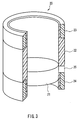
- FIG. 3 is a partially sectional view showing the configuration of a component 20 supported in the lens support mechanism 100.
- the lens support mechanism 100 includes the component 20.
- the component 20 includes a resin cylinder 22 having stepped portions at the both ends and a part formed with a fixing hole 25 penetrating into the inner periphery, and also cylindrical members 23 and 24 made of a material having a linear expansion coefficient the same as that of an optical head enclosure 3.
- the cylindrical members 23 and 24 are fitted respectively to the ends of the resin cylinder 22, and integrated with the resin cylinder 22.
- the collimator lens 21 is inserted into the component 20 and fixed to the component 20 by filling the fixing hole 25 with an adhesive.
- FIG. 1 illustrates the component 20 in an attached state.
- a V-shaped groove 4 for housing the component 20 is formed in order to set the center of the collimator lens 21 at a predetermined optical axis position.
- the center of the collimator lens 21 is defined at the optical axis position.
- the component 20 is configured as a structure satisfying Conditional expression 1 below.
- ⁇ y ⁇ ⁇ x - ⁇ z - ⁇ fb a back focus variation per unit temperature of the collimator lens 21, ⁇ : a linear expansion coefficient of the optical head enclosure 3 (unit: /K), ⁇ : a linear expansion coefficient of the resin cylinder 22 of the component 20 (unit: /K), ⁇ : a linear expansion coefficient of a stem 11 provided to the semiconductor laser 10 (unit: /K),
- x a distance from a reference surface 5 for attachment of the semiconductor laser 10 to a position at which the resin cylinder 22 and the cylindrical member 23 of the component 20 fit to each other
- y a distance from a position at which the resin cylinder 22 and the cylindrical member 23 of the component 20 fit to each other to a position at which the collimator lens 21 is fixed
- z a distance from a reference surface 5 for
- This Conditional expression 1 is for setting a distance (y) from a position at which the resin cylinder 22 and the cylindrical member 23 of the component 20 fit to each other to a position at which the collimator lens 21 is fixed, so that a shift variation ( ⁇ y) per unit temperature of a distance y from the position at which the resin cylinder 22 and the cylindrical member 23 of the component 20 fit to each other to the position at which the collimator lens 21 is fixed will be equal substantially to a value obtained by differentiating, from a shift variation ( ⁇ x) per unit temperature of a distance x from the reference surface 5 for attachment of the semiconductor laser 10 of the optical head enclosure 3 to a position at which the resin cylinder 22 and the cylindrical member 23 of the component 20 fit to each other, the sum of the shift variation per unit temperature of the emission point 12 and a back focus variation per unit temperature of the collimator lens 21.
- the defocus is not so much as to affect the entire optical system configuring the optical head device.
- the distance y from a position at which the resin cylinder 22 and the cylindrical member 23 fit to each other to a position at which the collimator lens 21 is fixed can be set constantly even when the temperature changes, regardless of the amount of the adhesive and variation of the fixing positions.
- the resin cylinder 22 expands and contract along the optical axis direction in order to reduce the deviation in the distance between the emission point 12 of the semiconductor laser 10 and the collimator lens 21, thereby accommodating the deviation caused by the expansion and contraction, and thus preventing the occurrence of deviation in focal length of the collimator lens 21 attached to the interior of the resin cylinder 22 of the component 20.
- the optical head enclosure 3 is made of aluminum
- the resin cylinder 22 of the component 20 is made of polycarbonate
- the cylindrical members 23 and 24 are made of aluminum
- the stem 11 provided to the semiconductor laser 10 is made of copper.
- ⁇ x - ⁇ z - ⁇ fb 0.1414 ⁇ m, satisfying the condition of ⁇ y ⁇ ⁇ x - ⁇ z - ⁇ fb.
- the defocus amount per unit temperature can be set to 0.0014 ⁇ m so as to obtain preferable temperature characteristics.
- the resin cylinder 22 of the component 20 is made of polycarbonate
- the cylindrical members 23 and 24 are made of zinc
- the stem 11 of the semiconductor laser 10 is made of copper
- ⁇ 33 ⁇ 10E -6
- ⁇ 70 ⁇ 10E -6
- ⁇ 17 ⁇ 10E -6
- x 12.6 mm
- y 5.1 mm
- z 1.3 mm
- ⁇ fb 0.036 ⁇ m.
- ⁇ x - ⁇ z - ⁇ fb 0.358 ⁇ m, satisfying the condition of ⁇ y ⁇ ⁇ x - ⁇ z - ⁇ fb.
- the defocus amount per unit temperature can be set to 0.001 ⁇ m so as to obtain preferable temperature characteristics.
- the optical head enclosure 3 is made of magnesium
- the resin cylinder 22 of the component 20 is made of polycarbonate
- the cylindrical members 23 and 24 are made of zinc
- the stem 11 of the semiconductor laser 10 is made of copper
- ⁇ 25.6 ⁇ 10E -6
- ⁇ 70 ⁇ 10E -6
- ⁇ 17 ⁇ 10E -6
- x 10.5 mm
- y 3.0 mm
- z 1.3 mm
- ⁇ fb 0.036 ⁇ m.
- ⁇ x - ⁇ z - ⁇ fb 0.2107 ⁇ m, satisfying the condition of ⁇ y ⁇ ⁇ x - ⁇ z - ⁇ fb.
- the defocus amount per unit temperature can be set to 0.0007 ⁇ m so as to obtain preferable temperature characteristics.
- the optical head enclosure 3 is made of polyphenylene sulfide
- the resin cylinder 22 of the component 20 is made of polycarbonate
- the cylindrical members 23 and 24 are made of zinc
- the stem 11 of the semiconductor laser 10 is made of copper
- ⁇ 19.9 ⁇ 10E -6
- ⁇ 70 ⁇ 10E -6
- ⁇ 17 ⁇ 10E -6
- x 9.3 mm
- y 1.8 mm
- z 1.3 mm
- ⁇ fb 0.036 ⁇ m.
- ⁇ x - ⁇ z - ⁇ fb 0.12697 ⁇ m, satisfying the condition of ⁇ y ⁇ ⁇ x - ⁇ z - ⁇ fb.
- the defocus amount per unit temperature can be set to 0.00097 ⁇ m so as to obtain preferable temperature characteristics.
- the optical head enclosure 3 is made of aluminum, zinc, magnesium or polyphenylene sulfide resin
- the collimator lens 21 faces the semiconductor laser 10
- the resin cylinder 22 of the component 20 is made of polycarbonate.
- the present invention is not limited to this example, but any combination of configurations satisfying the above-mentioned Conditional expression 1 can be used.
- the component in this embodiment is configured separately and assembled integrally with the collimator lens, the component and the collimator lens can be configured integrally.
- lens support mechanism according to the present invention can be applied to other optical systems.
- the optical head device has a plurality of semiconductor lasers whose wavelengths are different from each other, one lens support mechanism is provided for each of the semiconductor lasers.
- one lens support mechanism is provided for each of the semiconductor lasers.
- a cylindrical member 23 fitted to the resin cylinder 22 on the side of the collimator lens 21 opposite to the semiconductor laser 10 and formed so as to be fixed to the optical head enclosure 3 has substantially the same linear expansion coefficient as the linear expansion coefficient of the optical head enclosure 3.
- the cylindrical member 23 will thermally expand or thermally contract so as to accommodate the thermal expansion or thermal contraction of the optical had enclosure 3, thereby preventing the occurrence of optical axis deviation or focal length deviation of the collimator lens 21.
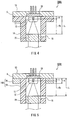
- FIG. 4 is a cross-sectional view showing a configuration of a lens support mechanism 100A according to a second embodiment.
- the lens support mechanism 100A has a semiconductor laser support base 13 with a semiconductor laser 10.
- the semiconductor laser support base 13 is equipped in a frame member 14 shaped like a substantial hollow cylinder.
- a collimator lens 21 is inserted into the frame member 14.
- the collimator lens 21 is fixed to the frame member 14 by filling a fixing hole 15 formed in the frame member 14 with an adhesive, and defined at a predetermined optical axis position.
- the frame member 14 is made of a ceramic material that does not change its shape substantially regarding temperature change, preferable temperature characteristics can be obtained.
- the frame member 14 is formed as a lens support structure satisfying Conditional expression 2 below.
- ⁇ z ⁇ z
- ⁇ fb a back focus variation per unit temperature of the collimator lens 21
- ⁇ L a shift per unit temperature of a distance from a reference surface 5 for attachment of the semiconductor laser 10 to a position at which the collimator lens 21 is fixed
- ⁇ a linear expansion coefficient of a stem 11 of the semiconductor laser 10 (unit: /K)
- z a distance from a reference surface 5 for attachment of the semiconductor laser to an emission point
- fb a focal length of the collimator lens
- L a distance from the reference surface 5 for attachment of the semiconductor laser to the position at which the collimator lens 21 is fixed.
- the ceramic material of the frame member 14 is a cordierite ceramic
- the stem 11 of the semiconductor laser 10 is made of copper
- the cordierite ceramic has a linear expansion coefficient of -5.0 ⁇ 10E -7 (unit: /K)
- ⁇ z 17 ⁇ 10E -6 ⁇ 1.3
- ⁇ 10E +3 0.0221 ⁇ m
- ⁇ fb 0.036 ⁇ m.
- a cordierite ceramic was used for the material of the component 20.
- the present invention is not limited to this example, but the component 20 can be made of any ceramics or the like that will not change substantially with respect to a temperature change.
- lens support mechanism of the present invention can be applied to other optical systems.
- the optical head device has a plurality of semiconductor lasers having wavelengths different from each other, one lens support mechanism is provided for each of the semiconductor lasers so that parallel light will be emitted stably from this collimator lens even when the temperature changes.
- a preferable temperature characteristic that the collimator lens will not be defocused with respect to the semiconductor laser can be obtained. In this manner, an operation environment in a wide temperature range from a low temperature to a high temperature can be assured.
- FIG. 5 is a cross-sectional view showing a configuration of a lens support mechanism 100B according to a third embodiment.
- a frame member 14A includes a ceramic cylinder 19 having a fixing hole 15 formed at a part thereof and penetrating to the inner periphery, and a plate 16 made of a material having a linear expansion coefficient the same as that of a laser support base 13.
- the plate 16 is fitted at one end of the ceramic cylinder 19, and configured integrally with the ceramic cylinder 19.
- the plate 16 will expand and contract similarly to the laser support base 13 since the ceramic cylinder 19 is fitted to the plate 16 made of a material having the same linear expansion coefficient as the laser support base 13, thereby preventing the occurrence of optical axis deviation of the collimator lens 21 attached to the ceramic cylinder 19.
- the collimator lens 21 is inserted into the ceramic cylinder 19 and fixed to the frame member 14A by filling the fixing hole 15 with an adhesive.
- This frame member 14A is configured as a lens support structure that satisfies Conditional expression 3 below.
- ⁇ z ⁇ z
- ⁇ t ⁇ t
- ⁇ fb a back focus variation per unit temperature of the collimator lens 21
- ⁇ L a shift per unit temperature of a distance from a reference surface 5 for attachment of the semiconductor laser 10 to a position at which the collimator lens 21 is fixed
- ⁇ a linear expansion coefficient of the laser support base 13 (unit:/K)
- ⁇ a linear expansion coefficient of the stem 11 of the semiconductor laser 10 (unit: /K)
- z a distance from the reference surface 5 for attachment of the semiconductor laser to an emission point 12
- fb a focal length of the collimator lens 21
- L a distance from the reference surface 5 for attachment of the semiconductor laser to a position at which the collimator lens 21 is fixed
- t a fitting thickness of the ceramic
- the ceramic material of the ceramic cylinder 19 is a cordierite ceramic
- the stem 11 of the semiconductor laser 10 is made of copper
- the cordierite ceramic has a linear expansion coefficient of -5.0 ⁇ 10E -7 (unit: /K)
- ⁇ z 17 ⁇ 10E -6 ⁇ 1.3
- ⁇ 10E +3 0.0221 ⁇ m
- ⁇ fb 0.036 ⁇ m.
- a cordierite ceramic was used for the material of the ceramic cylinder 19. Any ceramic materials or the like can be used as long as the materials experience substantially no change with respect to temperature change.
- lens support mechanism of the present invention can be applied to other optical systems.
- the optical head device has a plurality of semiconductor lasers having wavelengths different from each other, one lens support mechanism is provided for each of the semiconductor lasers so that parallel light will be emitted stably from this collimator lens even when the temperature changes.
- a preferable temperature characteristic that the collimator lens will not be defocused with respect to the semiconductor laser can be obtained. In this manner, an operation environment in a wide temperature range from a low temperature to a high temperature can be assured.
- FIG. 6 is a block diagram for schematically showing a configuration of an optical information processor 200 according to a fourth embodiment.
- the optical information processor 200 includes an optical head device 40 having the lens support mechanism 100 as described in the first embodiment.
- the optical head device 40 further has an objective lens 45.
- the objective lens 45 converges, onto an optical disk 41, a laser beam that has passed through a lens in the lens support mechanism 100.
- a motor 42 for supporting and rotating the optical disk 41 is provided to the optical information processor 200.
- the optical information processor 200 is provided with a servo mechanism 46.
- the servo mechanism 46 is provided in order to control a position of the objective lens 45 provided for the optical head device 40, on the basis of a focus error signal and a tracking error signal obtained from the optical head device 40.
- the optical information processor 200 includes an electric circuit 47 provided for controlling the servo mechanism 46, and a power source 44 for supplying power to the electric circuit 47, the servo mechanism 46 and to the motor 42. These electric circuit 47, servo mechanism 46, motor 42 and power source 44 are provided on a circuit board 43.
- the optical disk 41 is rotated by the motor 42.
- the optical head device 40 sends a signal corresponding to a positional relation with the optical disk 41 (focus error signal, tracking error signal) to the servo mechanism 46.
- the servo mechanism 46 calculates this signal and supplies the optical head device 40 with a signal for subtly shifting the position of either the optical head device 40 or the objective lens 45 within the optical head device 40 for the purpose of controlling the positions of the optical head 40 or the objective lens 45.
- the optical head device 40 performs focus servo and tracking servo with respect to the optical disk 41, and conducts reading, writing or erasing of information with respect to the optical disk 41.
- the power source can be provided outside the optical information processor 200.
- the present invention can provide a lens support mechanism an optical head device and an optical information processor that can accommodate positional deviation between an emission point and a collimator lens caused by thermal expansion and thermal contraction.
Landscapes
- Physics & Mathematics (AREA)
- Optics & Photonics (AREA)
- Optical Head (AREA)
- Lens Barrels (AREA)
- Optical Recording Or Reproduction (AREA)
Applications Claiming Priority (3)
| Application Number | Priority Date | Filing Date | Title |
|---|---|---|---|
| JP2002159083 | 2002-05-31 | ||
| JP2002159083 | 2002-05-31 | ||
| PCT/JP2003/006371 WO2003102940A1 (fr) | 2002-05-31 | 2003-05-22 | Mecanisme de support de lentille, dispositif a tete optique et unite de traitement d'informations optiques |
Publications (2)
| Publication Number | Publication Date |
|---|---|
| EP1511022A1 true EP1511022A1 (fr) | 2005-03-02 |
| EP1511022A4 EP1511022A4 (fr) | 2008-12-24 |
Family
ID=29706510
Family Applications (1)
| Application Number | Title | Priority Date | Filing Date |
|---|---|---|---|
| EP03730561A Withdrawn EP1511022A4 (fr) | 2002-05-31 | 2003-05-22 | Mecanisme de support de lentille, dispositif a tete optique et unite de traitement d'informations optiques |
Country Status (7)
| Country | Link |
|---|---|
| US (1) | US7123553B2 (fr) |
| EP (1) | EP1511022A4 (fr) |
| JP (1) | JP4299778B2 (fr) |
| KR (1) | KR100648447B1 (fr) |
| CN (1) | CN100351929C (fr) |
| AU (1) | AU2003242379A1 (fr) |
| WO (1) | WO2003102940A1 (fr) |
Families Citing this family (9)
| Publication number | Priority date | Publication date | Assignee | Title |
|---|---|---|---|---|
| DE10344504A1 (de) * | 2003-09-24 | 2005-05-25 | Deutsche Thomson-Brandt Gmbh | Abtasteinrichtung für ein Gerät zum Lesen oder Beschreiben optischer Aufzeichnungsträger |
| US7612951B2 (en) * | 2006-03-24 | 2009-11-03 | Konica Minolta Opto, Inc. | Projection lens unit |
| JP4589909B2 (ja) * | 2006-10-27 | 2010-12-01 | 株式会社日立メディアエレクトロニクス | 対物レンズ駆動装置 |
| AR070418A1 (es) * | 2009-02-12 | 2010-04-07 | Consejo Nac Invest Cient Tec | Metodo y aparato para determinar la dilatacion de un material mediante un dispositivo sensor de error de foco |
| EP3432524B1 (fr) | 2009-09-24 | 2024-05-01 | Zoom Video Communications, Inc. | Système et procédé d'identification de communication entre des serveurs virtuels |
| JP6398913B2 (ja) * | 2015-08-28 | 2018-10-03 | 京セラドキュメントソリューションズ株式会社 | 光源ユニット、光走査装置、画像形成装置 |
| JP6897004B2 (ja) * | 2016-04-15 | 2021-06-30 | オムロン株式会社 | 光学式センサ取付用アダプタおよび光学式センサの取付位置の調整方法 |
| JP6967480B2 (ja) * | 2018-03-30 | 2021-11-17 | パナソニック デバイスSunx株式会社 | レーザ発振器ユニット、レーザ加工装置 |
| CN115685569A (zh) * | 2021-07-21 | 2023-02-03 | 维林光电(苏州)有限公司 | 实现束腰位置稳定的半导体激光准直器 |
Family Cites Families (12)
| Publication number | Priority date | Publication date | Assignee | Title |
|---|---|---|---|---|
| US4918702A (en) * | 1987-12-02 | 1990-04-17 | Canon Kabushiki Kaisha | Laser unit |
| JPH03113842A (ja) | 1989-09-27 | 1991-05-15 | Canon Inc | レーザー光源装置 |
| JPH0643386A (ja) * | 1992-07-24 | 1994-02-18 | Nikon Corp | 光源部又は受光部の温度補償構造 |
| JPH09198697A (ja) | 1996-01-18 | 1997-07-31 | Matsushita Electric Ind Co Ltd | 光情報処理装置 |
| JPH10193680A (ja) * | 1997-01-10 | 1998-07-28 | Fujitsu Ltd | 光源装置とそれを用いた画像形成装置 |
| JP2000123392A (ja) | 1998-10-14 | 2000-04-28 | Asahi Optical Co Ltd | レーザーダイオードユニット |
| JP2000242961A (ja) | 1999-02-22 | 2000-09-08 | Yamaha Corp | 光ヘッドのレンズ支持構造および光ヘッド |
| JP4147670B2 (ja) | 1999-02-22 | 2008-09-10 | ヤマハ株式会社 | 光ヘッドのレンズ支持構造 |
| JP2000266977A (ja) | 1999-03-12 | 2000-09-29 | Yamaha Corp | 光学装置 |
| JP2002074734A (ja) * | 2000-09-01 | 2002-03-15 | Sony Corp | 光ヘッドおよび光ピックアップ |
| JP4413417B2 (ja) * | 2000-12-18 | 2010-02-10 | 古河電気工業株式会社 | レーザダイオードモジュール |
| US6710932B2 (en) * | 2001-12-17 | 2004-03-23 | Matsushita Electric Industrial Co., Ltd. | Zoom lens system with temperature compensation function and video camera using the same |
-
2003
- 2003-05-22 JP JP2004509940A patent/JP4299778B2/ja not_active Expired - Lifetime
- 2003-05-22 EP EP03730561A patent/EP1511022A4/fr not_active Withdrawn
- 2003-05-22 AU AU2003242379A patent/AU2003242379A1/en not_active Abandoned
- 2003-05-22 WO PCT/JP2003/006371 patent/WO2003102940A1/fr not_active Ceased
- 2003-05-22 KR KR1020047019106A patent/KR100648447B1/ko not_active Expired - Lifetime
- 2003-05-22 US US10/512,897 patent/US7123553B2/en not_active Expired - Lifetime
- 2003-05-22 CN CNB038126109A patent/CN100351929C/zh not_active Expired - Fee Related
Also Published As
| Publication number | Publication date |
|---|---|
| WO2003102940A1 (fr) | 2003-12-11 |
| AU2003242379A1 (en) | 2003-12-19 |
| US7123553B2 (en) | 2006-10-17 |
| JP4299778B2 (ja) | 2009-07-22 |
| EP1511022A4 (fr) | 2008-12-24 |
| US20050190665A1 (en) | 2005-09-01 |
| KR100648447B1 (ko) | 2006-11-24 |
| CN100351929C (zh) | 2007-11-28 |
| CN1659639A (zh) | 2005-08-24 |
| KR20040111704A (ko) | 2004-12-31 |
| JPWO2003102940A1 (ja) | 2005-09-29 |
Similar Documents
| Publication | Publication Date | Title |
|---|---|---|
| US7123553B2 (en) | Lens support mechanism, optical head device and optical information processor | |
| JP2003021770A (ja) | 対物レンズ、対物レンズの製造方法、光学ピックアップ装置及び記録再生装置 | |
| US6266315B1 (en) | Catadioptric optical system, optical pickup and optical disk drive employing the same, and optical disk | |
| US4641023A (en) | Optical head | |
| JP3792462B2 (ja) | 光ピックアップ装置およびその製造方法 | |
| US4856871A (en) | Replaceable laser and lens assembly | |
| JP3426081B2 (ja) | 光学素子の固定装置 | |
| US6272079B1 (en) | Optical head unit for optical disk apparatus having both focus control and track control function | |
| US20080298217A1 (en) | Optical pickup device, optical disc apparatus including optical pickup device, and method of manufacturing optical pickup device | |
| US7414926B2 (en) | Optical head device that prevents the displacement of the optical axis caused by expansion or contraction due to temperature change | |
| JP3980528B2 (ja) | 光ピックアップ | |
| EP0472084A2 (fr) | Tête optique | |
| JPH087313A (ja) | 光学ヘッド | |
| JP4253561B2 (ja) | 光ピックアップおよび光ディスクドライブ装置 | |
| JPH08111027A (ja) | 光ピックアップ装置 | |
| JP2003021773A (ja) | 対物レンズ、光学ピックアップ装置及び記録再生装置 | |
| JP2002197705A (ja) | 光ヘッド装置およびその製造方法 | |
| JPH0620297A (ja) | 光ピックアップ | |
| JP2009087495A (ja) | 光ピックアップ装置 | |
| JP2005108300A (ja) | 光ピックアップ装置 | |
| JP2004319064A (ja) | 光ヘッド装置および光記録媒体駆動装置 | |
| JPS6228936A (ja) | 光ピツクアツプ | |
| JP2004220665A (ja) | 光ピックアップ装置 | |
| JPH07225953A (ja) | 光源装置 | |
| JPH0443328B2 (fr) |
Legal Events
| Date | Code | Title | Description |
|---|---|---|---|
| PUAI | Public reference made under article 153(3) epc to a published international application that has entered the european phase |
Free format text: ORIGINAL CODE: 0009012 |
|
| 17P | Request for examination filed |
Effective date: 20041201 |
|
| AK | Designated contracting states |
Kind code of ref document: A1 Designated state(s): AT BE BG CH CY CZ DE DK EE ES FI FR GB GR HU IE IT LI LU MC NL PT RO SE SI SK TR |
|
| AX | Request for extension of the european patent |
Extension state: AL LT LV MK |
|
| DAX | Request for extension of the european patent (deleted) | ||
| RBV | Designated contracting states (corrected) |
Designated state(s): DE FR GB |
|
| RAP1 | Party data changed (applicant data changed or rights of an application transferred) |
Owner name: PANASONIC CORPORATION |
|
| A4 | Supplementary search report drawn up and despatched |
Effective date: 20081125 |
|
| STAA | Information on the status of an ep patent application or granted ep patent |
Free format text: STATUS: THE APPLICATION HAS BEEN WITHDRAWN |
|
| 18W | Application withdrawn |
Effective date: 20090216 |