EP1510436B1 - Fahrzeuglenksystem - Google Patents
Fahrzeuglenksystem Download PDFInfo
- Publication number
- EP1510436B1 EP1510436B1 EP04254331A EP04254331A EP1510436B1 EP 1510436 B1 EP1510436 B1 EP 1510436B1 EP 04254331 A EP04254331 A EP 04254331A EP 04254331 A EP04254331 A EP 04254331A EP 1510436 B1 EP1510436 B1 EP 1510436B1
- Authority
- EP
- European Patent Office
- Prior art keywords
- steering
- reaction force
- force actuator
- malfunction
- actuator
- Prior art date
- Legal status (The legal status is an assumption and is not a legal conclusion. Google has not performed a legal analysis and makes no representation as to the accuracy of the status listed.)
- Expired - Lifetime
Links
- 238000006243 chemical reaction Methods 0.000 claims description 97
- 230000007257 malfunction Effects 0.000 claims description 46
- 230000007246 mechanism Effects 0.000 claims description 23
- 238000001514 detection method Methods 0.000 claims description 17
- 230000003247 decreasing effect Effects 0.000 claims description 4
- 230000001419 dependent effect Effects 0.000 claims 1
- 230000007704 transition Effects 0.000 description 10
- 238000006073 displacement reaction Methods 0.000 description 9
- 230000002950 deficient Effects 0.000 description 7
- 230000006870 function Effects 0.000 description 7
- 238000000034 method Methods 0.000 description 7
- 230000007423 decrease Effects 0.000 description 4
- 230000007547 defect Effects 0.000 description 4
- 230000008859 change Effects 0.000 description 3
- 238000002474 experimental method Methods 0.000 description 1
- 238000012986 modification Methods 0.000 description 1
- 230000004048 modification Effects 0.000 description 1
- 230000003334 potential effect Effects 0.000 description 1
- 230000008569 process Effects 0.000 description 1
Images

Classifications
-
- B—PERFORMING OPERATIONS; TRANSPORTING
- B62—LAND VEHICLES FOR TRAVELLING OTHERWISE THAN ON RAILS
- B62D—MOTOR VEHICLES; TRAILERS
- B62D5/00—Power-assisted or power-driven steering
- B62D5/04—Power-assisted or power-driven steering electrical, e.g. using an electric servo-motor connected to, or forming part of, the steering gear
- B62D5/0409—Electric motor acting on the steering column
-
- B—PERFORMING OPERATIONS; TRANSPORTING
- B62—LAND VEHICLES FOR TRAVELLING OTHERWISE THAN ON RAILS
- B62D—MOTOR VEHICLES; TRAILERS
- B62D5/00—Power-assisted or power-driven steering
- B62D5/001—Mechanical components or aspects of steer-by-wire systems, not otherwise provided for in this maingroup
- B62D5/003—Backup systems, e.g. for manual steering
-
- B—PERFORMING OPERATIONS; TRANSPORTING
- B62—LAND VEHICLES FOR TRAVELLING OTHERWISE THAN ON RAILS
- B62D—MOTOR VEHICLES; TRAILERS
- B62D5/00—Power-assisted or power-driven steering
- B62D5/04—Power-assisted or power-driven steering electrical, e.g. using an electric servo-motor connected to, or forming part of, the steering gear
- B62D5/0457—Power-assisted or power-driven steering electrical, e.g. using an electric servo-motor connected to, or forming part of, the steering gear characterised by control features of the drive means as such
- B62D5/0481—Power-assisted or power-driven steering electrical, e.g. using an electric servo-motor connected to, or forming part of, the steering gear characterised by control features of the drive means as such monitoring the steering system, e.g. failures
- B62D5/0487—Power-assisted or power-driven steering electrical, e.g. using an electric servo-motor connected to, or forming part of, the steering gear characterised by control features of the drive means as such monitoring the steering system, e.g. failures detecting motor faults
Definitions
- the present invention generally relates to a vehicle steering system.
- the present invention more specifically relates a vehicle steering system having a mechanical steering system and a steer-by-wire steering system where the steer-by-wire steering system is connected in normal operating situations and selectively disconnected in defective situations.
- a vehicle steering system which is capable of varying a steering characteristic by varying the ratio between an amount of operation of an operating member (steering wheel) and an amount of turning of the vehicle steered wheels.
- movement of the operating member operates a steering actuator to transmit a steering force to the vehicle steered wheels in order to vary the turning angle.
- a so-called steer-by-wire system is known as a so-called steer-by-wire system.
- the operating member is not mechanically connected to the vehicle steered wheels (normal operating situations).
- the ratio between the amount of operation and the amount of steering is varied by controlling the steering actuator, without mechanically connecting the steering wheel to the vehicle steered wheels, when movement of a steering actuator is transmitted to the vehicle steered wheels in order to vary the steering angle through a steering gear unit actuator.
- a reaction force is applied to the steering wheel based on friction with the road surface such as steering resistance to provide the driver with a steering feeling similar to a mechanically connected steering system.
- the steering wheel and the vehicle steered wheels are disconnected in normal situations, and a steering reaction force actuator and a steering gear unit actuator are operated to provide a steering reaction force to the steering wheel and a turning force to the vehicle steered wheels.
- a clutch is brought into engagement to mechanically connect the steering wheel to the vehicle steered wheels and apply a steering assist force.
- one proposed object of the present invention is to provide a vehicle steering system that can make displacement of the vehicle steered wheels small and prevent the vehicle from tracking misaligned when the steering reaction force actuator is found to be malfunctioning and when the steering control is changing from a normal steering actuation mode to a backup steering actuation mode.
- DE 101 01 827 A1 discloses a vehicle steering system in accordance with the preamble of claim 1.
- DE 101 35 736 C1 discloses a vehicle steering system with a steering controller which includes multiple redundant components. When malfunction of a number of the components is detected, the steering wheel is mechanically connected to a steering mechanism by a clutch.
- DE 198 38 490 A1 discloses a vehicle steering system in which the steering wheel is mechanically connected to a steering mechanism if a malfunction occurs in the steering control system.
- the present invention provides a vehicle steering system as set forth in claim 1.
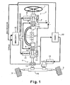
- Figure 1 is an overall view of a vehicle steering system in accordance with a first embodiment of the present invention
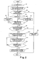
- Figure 2 is a flow chart of the steer-by-wire control processing conducted by the steer-by wire control of the first embodiment of the present invention.
- Figure 3 is four time charts comparing a steering controller operating in accordance with the present invention with a conventional steering controller regarding the current surge, the steering wheel angle, the turning (tire) angle, and the widthwise displacement of the vehicle, when the steering reaction force actuator is malfunctioning.
- a vehicle steering system is illustrated in accordance with a first embodiment of the present invention.
- the vehicle steering system illustrated in Figure 1 is a steer-by-wire (SBW) system with a backup steering actuation mode.
- SBW steer-by-wire
- the vehicle steering system is provided with a primary steer-by-wire steering system and a secondary backup mechanical steering system in which a control system switches from the primary steering system to the backup steering system when a defect or malfunction is determined in the primary steering system.
- the vehicle steering system of the present embodiment basically comprises a steering wheel 1 (operation input member), an operation part 2, a pair of steerable vehicle wheels 3, a steering mechanism or turning part 4, a first clutch 5, a second clutch 6, a steering wheel angle sensor 7, a steering reaction force actuator 8, a first steering column shaft 9, a second steering column shaft 10, a steering gear unit actuator 11, a turning angle sensor 12, a torque sensor 13, a first pinion shaft 14, a second pinion shaft 15, a steering gear mechanism 16, a cable mechanism 17, a first steer-by-wire controller 18, a steering gear assisting motor 19, and a second steering assisting controller 20.
- the steering wheel 1, the steering wheel angle sensor 7, the steering reaction force actuator 8 are situated at the first steering column shaft 9 of the operation part 2.
- the first clutch 5 is preferably an electronic magnetic clutch or the like that can be remotely connected and disconnected.
- the first clutch 5 is situated between the first steering column shaft 9 and the second steering column shaft 10 for selectively connecting and disconnecting the first steering column shaft 9 to and from the second steering column shaft 10.
- the steering gear unit actuator 11, the turning angle sensor 12, the torque sensor 13 are situated at the second pinion shaft 15 of the turning part 4.
- the second clutch 6 is preferably an electronic magnetic clutch or the like that can be remotely connected and disconnected.
- the second clutch 6 is situated between the first pinion shaft 14 of the turning part 4 and the second pinion shaft 15 of the turning part 4 for selectively connecting and disconnecting the first pinion shaft 14 to and from the second pinion shaft 15.
- the vehicle steering system of the present invention is configured to make the displacement of the steerable vehicle wheels 3 small and prevent the vehicle from tracking misaligned when a malfunction is found in the steering reaction force actuator 8 and when the control system shifts to the backup steering actuation mode in the period of transition.
- the control command to the steering gear unit actuator 8 is restricted from the point when the steering reaction force actuator 8 is determined to be malfunctioning to the point when the clutches 5 and 6 are fully engaged, i.e., the clutches 5 and 6 complete to mechanically connect the steering wheel 1 and the steerable vehicle wheels 3.
- the steering gear mechanism 16 is a rack-and-pinion type of steering mechanism that is operatively coupled to bottom of the second pinion shaft 15 in a conventional manner.
- the steerable vehicle wheels 3 are situated, so that they can be turned to change the turning angle of the vehicle by shifting a rack gear axis, in both sides of the steering gear mechanism 16.
- the cable mechanism 17 is situated between the operation part 2 and the turning part 4.
- the cable mechanism 17 forms a backup steering mechanism that mechanically couples the operation part 2 and the turning part 4 together when both the clutches 5 and 6 are connected.
- the cable mechanism 17 has a first cable reel 17a that is coupled to the end of the second steering column shaft 10, and a second cable reel 17b that is coupled to the end of the first pinion shaft 14.
- the cable mechanism 17 also has a first cable 17c and a second cable 17d operatively connected to the first and second cable reels 17a and 17b.
- the first and second cables 17c and 17d are each wound in different directions on the first and second cable reels 17a and 17b, in order to operatively connect the operation part 2 and the turning part 4.
- this cable mechanism 17 functions as a column shaft by transmitting a steering torque from the steering wheel 1 to the steerable vehicle wheels 3 through the cables 17c and 17c, and transmitting a reaction torque from the steerable vehicle wheels 3 the steering wheel 1.
- Both of the clutches 5 and 6 are situated in the middle of the steering system between the steering wheel 1 and the steerable vehicle wheels 3.
- the steering wheel 1 and the steerable vehicle wheels 3 are mechanically disconnected by releasing both of the clutches 5 and 6 in normal situations.
- the steering wheel 1 and the steerable vehicle wheels 3 are mechanically connected through the cable mechanism 17 by connecting the clutches 5 and 6.
- the first steer-by-wire controller 18 is configured and arranged to receive steering variation information or signals from the steering wheel angle sensor 7 and the turning angle sensor 13 including variation between the steering angle and the turning angle, and torque information or signal from the torque sensor 13. Based on these signals or information, the first steer-by-wire controller 18 is configured and arranged to output a reaction command to the steering reaction force actuator 8, a turning angle command to the steering gear unit actuator 11, and a control command of either connecting or disconnecting to the clutches 5 and 6.
- the second steering assisting controller 20 is configured and arranged to receive torque information or signal from the torque sensor 13 and a backup actuation mode information or signal from the first steer-by-wire controller 18. Based on these signals or information, the second steering assisting controller 20 is configured and arranged to outputs a drive assist command to assist steering torque that a driver needs based on the torque information or signal from the torque sensor 13, when the backup actuation mode information is received from the first steer-by-wire controller 18.
- the controllers 18 and 20 can be separate units or a single integrated unit that preferably includes a microcomputer with one or more steering control programs that control the vehicle steering system as discussed below.
- the controllers 18 and 20 can also include other conventional components such as an input interface circuit, an output interface circuit, and storage devices such as a ROM (Read Only Memory) device and a RAM (Random Access Memory) device.
- ROM Read Only Memory
- RAM Random Access Memory
- Figure 2 shows a flow chart for conducting the steer-by-wire control processing by the steer-by-wire controller 18 of the illustrated embodiment.
- This control logic is conducted repeatedly in control cycles at predetermined intervals.
- step S2 the first steer-by-wire controller 18 reads a detected value of the current occurring in the steering reaction force actuator 8.
- the first steer-by-wire controller 18 filters out the noise when obtaining the detected value of the current in the steering reaction force actuator 8.
- the current obtained from the steering reaction force actuator 8 contains noise, and therefore the detected current is filtered by, for example, using a moving average computation.
- the present invention is not limited to obtaining the detected value of the current by a moving average computation.
- a noise filter such as a low pass filter can be used instead.
- step S2 basically constitutes a steering reaction force actuator current detection method or section of the first steer-by-wire controller 18. Then, the processing proceeds to step S3.
- step S3 the steer-by-wire controller 18 determines whether or not the current in the steering reaction force actuator 8 is surge. If the current in the steering reaction force actuator 8 is surge, then the steer-by-wire controller 18 determines whether or not the current surge is greater than a preset surge threshold. Preferably, defective or malfunction situations of current (surge) in the steering reaction force actuator 8 are confirmed, when the absolute value of the difference between the target current value to the steering reaction force actuator 8 and the real current value obtained by the moving average computation is over the preset surge threshold. If the current surge is lower than the preset surge threshold (No), then the processing proceeds to step S4. However, if the current surge is greater than the preset surge threshold (Yes), then processing proceeds to step S5.
- a preset surge threshold Preferably, defective or malfunction situations of current (surge) in the steering reaction force actuator 8 are confirmed, when the absolute value of the difference between the target current value to the steering reaction force actuator 8 and the real current value obtained by the moving average computation is over the preset surge threshold. If the current surge is lower
- step S4 the steer-by-wire controller 18 continues conducting the normal control operation of the steering system, i.e., continues with steer-by-wire control, and then moves to the logic end.
- the normal control operation refers to a condition where the steer-by-wire controller 18 outputs turning angle commands to the steering gear unit actuator 11 for controlling the turning angle based on signals from the turning angle sensor 12, and outputs reaction force commands to the steering reaction force actuator 8 for providing the steering reaction force based on the reaction torque between the steerable vehicle wheels 3 and the road surface that is detected by the torque sensor 13 when the clutches 5 and 6 are released, e.g., the current being supplied to the clutches 5 and 6.
- step S7 the steer-by-wire controller 18 determines whether or not the surge is occurs for a period of time that is longer than a prescribed time ⁇ T. In other words, the steer-by-wire controller 18 determines whether or not there is a malfunction in the steering reaction force actuator 8 by detecting the surge current in the steering reaction force actuator 8. If the steer-by-wire controller 18 determines that the surge is occurring for a period of time that is longer than the prescribed time ⁇ T (Yes), then the processing continues to step S8. If the steer-by-wire controller 18 determines that the surge is occurring for a period of time that is shorter than the prescribed time T (No), then the processing proceeds to step S8.
- step S8 the steer-by-wire controller 18 continues conducting the normal control operation of the steering system, i.e., continues with steer-by-wire control, as discussed above with reference to step S4. Then, the processing by the steer-by-wire controller 18 proceeds back to step S2, where the current in the steering reaction force actuator 8 is again determined.
- the steer-by-wire controller 18 continues in this control loop until the surge level falls below the preset surge threshold as determined in step S3 (No), or until the surge level continues to exist above the preset surge threshold for a period of time that is longer than the prescribed time T as determined in step S7 (Yes).
- step S9 the steer-by-wire controller 18 counts how many times the preset surge threshold has been exceeded for the prescribed time ⁇ T. In other words, in step S9, the steer-by-wire controller 18 starts a counter for counting the number of consecutive times that the current in the steering reaction force actuator 8 has exceeded the preset threshold for the prescribed time ⁇ T. If a control cycle without detecting a surge occurs after a control cycle in which a surge is detected above the preset surge threshold for the prescribed time ⁇ T, then the counter in step S9 is reset. Basically, steps S3, S7, and S9 of the control loop constitute a steering malfunction detection method or section of the steer-by-wire controller 18.
- step S9 of the illustrated embodiment determines, in step S9 of the illustrated embodiment, a malfunction in the steering reaction force actuator 8 by counting two consecutively control cycles with surges above the preset surge threshold for the prescribed time T
- step S9 can be eliminated if desired or can be modified so that more than two consecutive surge above the preset surge threshold for the prescribed time T must be detected to proceed to step S 10.
- step S9 can be modified so as to determine whether more than a predetermined number of surges occur above the preset surge threshold for the prescribed time ⁇ T (whether consecutive or not) within a prescribed number of control cycles.
- step S9 if the steer-by-wire controller 18 counts two times consecutively that the current in the steering reaction force actuator 8 exceeding the preset threshold for the prescribed time ⁇ T in step S9, then the steering reaction force actuator 8 is determined to be defective or malfunctioning in step S9 and the processing by the steer-by-wire controller 18 proceeds to step S10 to start preparing for the back up actuation mode.
- step S9 If the steer-by-wire controller 18 does not count two times consecutively that the current in the steering reaction force actuator 8 exceeding the preset threshold for the prescribed time ⁇ T in step S9, then the steering reaction force actuator 8 proceeds to step S4 where the steer-by-wire controller 18 continues conducting the normal control operation of the steering system, i.e., continues with steer-by-wire control, as discussed above.
- step S10 the current to the steering reaction force actuator 8 is disconnected based on the determination of a malfunction in the steering reaction force actuator 8 in step S9.
- both the clutches 5 and 6 are connected.
- the steer-by-wire controller 18 proceeds to step S11.
- Both of the clutches 5 and 6 are connected when the current is turned off, e.g., current is not being supplied, to the clutches 5 and 6.
- both of the clutches 5 and 6 are disconnected when the current is turned on, e.g., current is being supplied to the clutches 5 and 6.
- both the clutches 5 and 6 are connected in step S10 by the steer-by-wire controller 18 outputting a command to supply current to the clutches 5 and 6.
- step S11 the first steer-by-wire controller 18 outputs a steering angle command to the steering gear unit actuator 11 such that the control gain decreases or becomes zero.
- step S12 the first steer-by-wire controller 18 determines whether or not the predetermined time has elapsed for connecting the first and second clutches 5 and 6. If the first steer-by-wire controller 18 determines the predetermined time has elapsed (Yes), then the processing continues to step S13. If in step S12, the first steer-by-wire controller 18 determines the predetermined time has not yet elapsed (No), then the processing proceeds back to step S 11.
- both of the clutches 5 and 6 are preferably of the types that are connected when current is cut off. For theses types of clutches, there is a mechanical dampening time constant to actually connect after the current is cut off.
- the predetermined time in step S12 is set to a length of time that is need for both of the clutches 5 and 6 to be connected.
- the predetermined time in step S12 can be calculated experimentally from data based on experiments that measure the reaction delay time from the current cut off to the completion of the connection.
- each actuator 8 and 11 moves to the back up actuation mode with the back up actuation, and then the processing proceeds to the logic end.
- the back up actuation mode is the situation in which both of the clutches 5 and 6 are connected by the current cut off and in which the steering reaction and the turning force are not given.
- the back up actuation mode is the situation in which a normal mechanical steering system is used to transmit the steering inputs from the steering wheel 1 to the steerable vehicle wheels 3.
- the motor power steering actuation that provides assist torque to decrease the steering torque that drivers provide is conducted by utilizing the torque sensor 13 and the steering gear assisting motor 19 during the operation at the second steering assisting controller 20.
- step S4 the normal control operation is conducted using the turning angle control and the steering reaction control such that the steerable vehicle wheels 3 are turned based on the driver's operation of the steering wheel 1.
- step S 1 When the steering reaction force actuator 8 is initially determined as possibly being defective or malfunctioning, then the processing proceeds from step S 1 to step S2, to step S3, to step S5, to step S6, to step S7, to step S8 and then back to step S2.
- This loop continues until the prescribed time ⁇ T has elapsed as determined by step S7. If the surge did not occur for longer than the prescribed time ⁇ T (No in step S7), then normal control operation continues. In other words, when the control process loops back from step S7 to step S3, if the surge has stopped before the prescribed time ⁇ T, the detected current will have fallen below the preset surge threshold and the processing will proceed to step S4 (normal control operation).
- step S10 the current to the steering reaction force actuator 8 is cut off, and both the clutches 5 and 6 are connected.
- the control gain of the steering gear unit actuator 11 decreases or becomes zero.
- step S12 the first steer-by-wire controller 18 determines whether or not the predetermined time for connecting the first and second clutches 5 and 6 has elapsed.
- step S12 as long as the predetermined time has not elapsed, the processing continues back to step S11.
- step S12 if the predetermined time has been determined to have elapsed, then the processing proceeds from step S12 to step S13 and moves to the back up actuation mode.
- both the clutches 5 and 6 are connected and the steering 1 and the steerable vehicle wheels 3 are connected in defective or malfunctioning situations.
- This defective or malfunctioning sequence is completed by occurrence of a malfunction in the steering reaction force actuator 8, the needed time to detect a malfunction in the steering reaction force actuator 8, and the connection of the clutches 5 and 6 in chronological order.
- the steering wheel 1 rotates freely until both of the clutches 5 and 6 are connected after the detection of a malfunction in the steering reaction force actuator 8.
- the steering wheel angle sensor 7 takes the angle data from the steering wheel 1 as a basis for controlling the steering gear unit actuator 11. If the steering gear unit actuator 11 is operated normally, based on the value from the steering wheel angle sensor 7 after the steering reaction force has stopped and the clutches 5 and 6 are not fully engaged, then the steering gear unit actuator 11 will over react.
- the first steer-by-wire controller 18 responds by decreasing the control gain K or making the control gain K equal to zero after detecting a malfunction in the steering reaction force actuator 8.
- the actuation displacement is limited or the value from the steering gear unit actuator 11 is kept the same for certain time until the clutches 5 and 6 are fully engaged right after the detection of a malfunction in the steering reaction force actuator 8.
- the displacements of the steerable vehicle wheels 3 are limited and an undesirable vehicle behavior can be small.
- Figure 3 illustrates time charts that show the defective or malfunctioning situation of the steering reaction force actuator 8, and that shows control executed by the steer-by-wire controller 18 in chronological order. From the top, Figure 3 shows the determination of surge, the steering angle (the steering wheel angle), the turning angle (tire angle), and the displacement of the vehicle in the widthwise direction.
- the point A represents when a surge starts occurring.
- the end point B represents when a malfunction in the steering reaction force actuator 8 is determined, while the end point C represents when both the clutches 5 and 6 are connected. If the detected surge exceeded a preset surge threshold at the point A, then the surge examination that was off during the period prior to point A as represented by line31, turns "on" during the period between the points A and B as represented by line 32, such that the steering wheel 1 is kept rotating in one direction by the steering reaction force actuator 8.
- the lines 32, 34, and 38 of the time charts represent the influences by the surge on the steering of the vehicle. In this case, because the steering wheel angle sensor 7 identifies the angle of the steering wheel 1, the steering gear unit actuator 11 that is operating normally moves during this time period between the points A and B.
- the steer-by-wire controller 18 keeps controlling the steering gear unit actuator 11 in time period between the points B and C, i.e., prior to both of the clutches 5 and 6 being fully connected, then the turning angle of the steerable vehicle wheels 3 will turn, in the same direction as the steering wheel 1 as shown by the line 39 in time period between the points B and C of Figure 3.
- the turning angle limits the actuation of the steering wheel 1 during the predetermined time.
- the time period after the point C is a situation where both the clutches 5 and 6 are connected and the steering wheel 1 and the steerable vehicle wheels 3 are fully mechanically connected.
- this time period after the point C there is large difference in change in the turning angle as seen by the arrow I.
- the turning angle is small with the transition limiting control and the turning angle is large without the transition limiting control.
- the transition limiting control as shown by the line 37 in time period after the point C of Figure 3, the driver need to steer the steering wheel 1 sharply backwards after the back up actuation mode because the turning angle was too large when the steering wheel 1 and the steerable vehicle wheels 3 are not mechanically connected.
- the transition limiting control as shown by the line 36 in time period after the point C of Figure 3, the operation can be easier after the mechanical back up actuation mode because the turning angle was small when the steering wheel 1 and the steerable vehicle wheels 3 were being connected, so that the driver can steer the steering wheel 1 gently backward with the limited amount of operation to make the vehicle behave in the desired manner.
- the present invention relates to a vehicle steering system comprising a primary steering system that applies a steering reaction force to a steering wheel (operation input member) and a steering gear unit controlling a steerable wheel in normal situations, and wherein at least one clutch is disposed in the steering system between the steering wheel and the steerable vehicle wheel, such that the control system engages the at least one clutch and switches to a secondary backup mechanical steering system when a defect or malfunction is determined in the primary steering system.
- the steering control method of the steering controller 18 conducts control of the drive of the steering reaction force actuator 8 and the steering gear unit actuator 11 in normal situations based on operation input information to the steering wheel 1.
- the malfunction detection method of the steering controller 18 is configured to detect malfunctions of the steering reaction force actuator 8.
- the steering control limiting method or section of the steering controller 18 is configured to make, when malfunctions are detected, the vehicle's tracking misalignment small at the transition period by changing from the actuation mode to the backup actuation mode because the steering control limiting method or section of the steering controller 18 limits the control commands from when malfunctions are detected at the steering reaction force actuator 8 to when both the clutches 5 and 6 are connected.
- step S 1 detects current on the steering reaction force actuator 8 and recognize the surge on the steering reaction force actuator 8 when absolute value of the difference between target current to the steering reaction force actuator 8 and the real current by moving average of the detected steering reaction force actuator current exceeds a predetermined threshold.
- the malfunction detection method counts the number of surges exceeding the predetermined threshold and recognizes a malfunction when it counts two consecutive surges.
- the illustrated embodiment shows the system where each one of the steering part and the turning part has an actuator, but the present invention also applies to a steering system where each one of the steering part and the turning part has at least one actuator.
- the illustrated embodiment shows the two clutch mechanisms (mechanically joining parts) and the cable mechanism (mechanical backup mechanism) in the steering system.
- the present invention includes a situation where only one clutch exists.
- the present invention can include any mechanical joint that connects and disconnects the steering wheel and the wheels as a backup mechanism so long as the steering wheel is rigidly connected to the steerable wheels to directly transmit the rotation of the steering wheel to the steerable wheels.
- the illustrated embodiment shows a system combining an SBW system and an electric power steering system, but a system without an electric power system is still acceptable.
- a system with a hydraulic power steering system can be used instead an electric power steering system.
Landscapes
- Engineering & Computer Science (AREA)
- Chemical & Material Sciences (AREA)
- Combustion & Propulsion (AREA)
- Transportation (AREA)
- Mechanical Engineering (AREA)
- Steering Control In Accordance With Driving Conditions (AREA)
- Power Steering Mechanism (AREA)
Claims (7)
- Fahrzeuglenksystem, das Folgendes umfasst:ein Bedieneingabeelement (1) zum Lenken eines Fahrzeugs;einen Lenkreaktionskraft-Aktuator (8), der so konfiguriert ist, dass er eine Reaktionskraft auf das Bedieneingabeelement (1) aufbringt;einen Lenkmechanismus (4) mit einem Lenkgetriebe-Aktuator (11) und wenigstens einem lenkbaren Fahrzeugrad (3), das betriebsmäßig mit dem Lenkgetriebe-Aktuator (11) gekoppelt ist;eine Kupplung (5, 6), die zwischen dem Bedieneingabeelement (1) und dem lenkbaren Fahrzeugrad (3) angeordnet ist und selektiv betätigt werden kann, um das Bedieneingabeelement (1) mechanisch von dem lenkbaren Fahrzeugrad (3) zu trennen und das Bedieneingabeelement (1) mechanisch mit dem lenkbaren Fahrzeugrad (3) zu verbinden; undeinen Lenkregler (18), der so konfiguriert ist, dass er den Lenkreaktionskraft-Aktuator (8) und den Lenkgetriebe-Aktuator (11) auf der Basis von Bedieneingabeinformationen in das Bedieneingabeelement (1) steuert, wobei der Lenkregler (18) einen Lenkfehlfunktionserfassungsteil aufweist, der so konfiguriert ist, dass er eine Fehlfunktion im Lenkreaktionskraft-Aktuator (8) erfasst;wobei der Lenkregler (18) und die Kupplung (5, 6) so konfiguriert sind, dass die Kupplung (5, 6) unter normalen Betriebsbedingungen, wenn keine Fehlfunktion des Lenkreaktionskraft-Aktuators (8) erfasst wird, das Bedieneingabeelement (1) mechanisch vom lenkbaren Fahrzeugrad (3) trennt, und die Kupplung (5, 6) das Bedieneingabeelement (1) nach der Erfassung einer Fehlfunktion des Lenkreaktionskraft-Aktuators (8) mechanisch mit einem lenkbaren Fahrzeugrad (3) verbindet;
wobei der Lenkregler (18) so konfiguriert ist, dass er an den Lenkgetriebe-Aktuator (11) einen Lenkwinkelbefehlswert (δ) anlegt, der unter normalen Betriebsbedingungen, wenn keine Fehlfunktion des Lenkreaktionskraft-Aktuators (8) erfasst wird, von den Bedieneingabeinformationen abhängig ist;
wobei der Lenkregler (18) so konfiguriert ist, dass er den Betrieb der Kupplung (5, 6) zum mechanischen Verbinden des Bedieneingabeelementes (1) mit dem lenkbaren Fahrzeugrad (3) nach dem Erfassen einer Fehlfunktion des Lenkreaktionskraft-Aktuators (8) einleitet;
wobei der Lenkregler (18) so konfiguriert ist, dass er die Steuerung des Lenkgetriebe-Aktuators (11) ab einem Erfassungspunkt, wenn eine Fehlfunktion im Lenkreaktionskraft-Aktuator (8) erfasst wird, bis zu einem Einrückpunkt fortsetzt, an dem ermittelt wird, dass die Kupplung (5, 6) die mechanische Verbindung zwischen dem Bedieneingabeelement (1) und dem lenkbaren Fahrzeugrad (3) vollzogen hat; und
wobei der Lenkregler (18) einen Lenkregelungsbegrenzungsteil aufweist, der so konfiguriert ist, dass er den Lenkwinkelbefehlswert (δ) nach dem Erfassungspunkt bis zu dem Einrückpunkt begrenzt;
dadurch gekennzeichnet, dassder Lenkregler (18) so konfiguriert ist, dass er den Lenkreaktionshaft-Aktuator (8) deaktiviert und den Betrieb der Kupplung (5,6) zum mechanischen Verbinden des Bedieneingabeelementes (1) mit dem lenkbaren Fahrzeugrad (3) einleitet, sobald eine Fehlfunktion des Lenkreaktionskraft-Aktuators (8) erfasst wird, undder Lenkregelungsbegrenzungsteil so konfiguriert ist, dass er den Lenkwinkelbefehlswert (δ) begrenzt, sobald eine Fehlfunktion des Lenkreaktionskraft-Aktuators (8) erfasst wird. - Fahrzeuglenksystem nach Anspruch 1, wobei der Lenkfehlfunktionserfassungsteil ferner so konfiguriert ist, dass er die Differenz zwischen einem erfassten Wert eines Stroms im Lenkreaktionskraft-Aktuator (8) und einem Sollstrom des Lenkreaktionskraft-Aktuators (8) erfasst und ermittelt, ob der Absolutwert der Differenz einen vorbestimmten Schwellenwert übersteigt.
- Fahrzeuglenksystem nach Anspruch 2, bei dem der erfasste Wert des Stroms ein gleitender Durchschnitt des Ist-Stroms im Lenkreaktionskraft-Aktuator (8) ist.
- Fahrzeuglenksystem nach Anspruch 2 oder 3, wobei der Lenkfehlfunktionserfassungsteil ferner so konfiguriert ist, dass er eine Fehlfunktion des Lenkreaktionskraft-Aktuators (8) erfasst, wenn der Absolutwert der Differenz den vorbestimmten Schwellenwert fiir eine vorbestimmte Zeitdauer weiter übersteigt.
- Fahrzeuglenksystem nach Anspruch 2 oder 3, wobei der Lenkfehlfunktionserfassungsteil ferner so konfiguriert ist, dass er zählt, wie oft der Absolutwert der Differenz den vorbestimmten Schwellenwert fiir eine vorbestimmte Zeitdauer übersteigt, und nach dem Erfassen von zwei aufeinander folgenden Auftretensfällen eine Fehlfunktion feststellt.
- Fahrzeuglenksystem nach einem der Ansprüche 1 bis 5, wobei der Lenkregler (18) ferner so konfiguriert ist, dass er den Strom zum Lenkreaktionskraft-Aktuator (8) nach dem Ermitteln einer Fehlfunktion im Lenkreaktionskraft-Aktuator (8) stoppt, und der Lenkregelungsbegrenzungsteil ferner so konfiguriert ist, dass er den Lenkwinkelbefehlswert durch Verringern einer Regelverstärkung zum Lenkgetriebe-Aktuator (11) oder durch Nullstellen der Regelverstärkung begrenzt.
- Fahrzeuglenksystem nach einem der Ansprüche 1 bis 6, wobei der Lenkmechanismus (4) ferner einen Servomotor (19) aufweist; undder Lenkregler (18) ferner so konfiguriert ist, dass er in einen Motorleistungslenkmodus umschaltet, nachdem das Bedieneingabeelement (1) und das lenkbare Fahrzeugrad (3) verbunden sind, auf der Basis der Erfassung einer Fehlfunktion im Lenkreaktionskraft-Aktuator (8).
Applications Claiming Priority (2)
| Application Number | Priority Date | Filing Date | Title |
|---|---|---|---|
| JP2003209393 | 2003-08-28 | ||
| JP2003209393 | 2003-08-28 |
Publications (3)
| Publication Number | Publication Date |
|---|---|
| EP1510436A2 EP1510436A2 (de) | 2005-03-02 |
| EP1510436A3 EP1510436A3 (de) | 2005-11-23 |
| EP1510436B1 true EP1510436B1 (de) | 2007-10-10 |
Family
ID=34100736
Family Applications (1)
| Application Number | Title | Priority Date | Filing Date |
|---|---|---|---|
| EP04254331A Expired - Lifetime EP1510436B1 (de) | 2003-08-28 | 2004-07-20 | Fahrzeuglenksystem |
Country Status (4)
| Country | Link |
|---|---|
| US (1) | US7004279B2 (de) |
| EP (1) | EP1510436B1 (de) |
| CN (1) | CN1330526C (de) |
| DE (1) | DE602004009375T2 (de) |
Cited By (1)
| Publication number | Priority date | Publication date | Assignee | Title |
|---|---|---|---|---|
| DE102019208200A1 (de) * | 2019-06-05 | 2020-12-10 | Volkswagen Aktiengesellschaft | Verfahren zum Betreiben eines Steer-by-Wire Lenksystems |
Families Citing this family (53)
| Publication number | Priority date | Publication date | Assignee | Title |
|---|---|---|---|---|
| JP4073856B2 (ja) * | 2003-10-08 | 2008-04-09 | 三菱電機株式会社 | 車両のロールオーバ判定装置 |
| JP4470565B2 (ja) * | 2004-04-09 | 2010-06-02 | 株式会社ジェイテクト | 車両用操舵装置 |
| JP4604566B2 (ja) * | 2004-06-17 | 2011-01-05 | 日産自動車株式会社 | 車両用操舵装置 |
| KR100535985B1 (ko) * | 2004-06-22 | 2005-12-09 | 현대모비스 주식회사 | 조작력 경감 기능을 갖춘 차량의 백업 조향장치 |
| US7500537B2 (en) * | 2004-08-25 | 2009-03-10 | Toyota Jidosha Kabushiki Kaisha | Steering apparatus for vehicle |
| JP4111191B2 (ja) * | 2004-12-28 | 2008-07-02 | 日産自動車株式会社 | 車両用操舵装置 |
| JP4682639B2 (ja) * | 2005-02-15 | 2011-05-11 | 日産自動車株式会社 | 操舵制御装置 |
| US7664584B2 (en) * | 2005-03-01 | 2010-02-16 | Nissan Motor Co., Ltd. | Steering control system |
| JP4725132B2 (ja) * | 2005-03-01 | 2011-07-13 | 日産自動車株式会社 | 操舵制御装置 |
| JP4792815B2 (ja) * | 2005-05-27 | 2011-10-12 | 日産自動車株式会社 | 車両用操舵装置 |
| US7604083B2 (en) * | 2005-06-07 | 2009-10-20 | Nissan Motor Co., Ltd. | Steering apparatus for a vehicle |
| JP4696702B2 (ja) * | 2005-06-07 | 2011-06-08 | 日産自動車株式会社 | 車両用操舵装置 |
| JP4839793B2 (ja) * | 2005-11-19 | 2011-12-21 | 日産自動車株式会社 | 車両用操舵制御装置 |
| JP2007153003A (ja) * | 2005-12-01 | 2007-06-21 | Nissan Motor Co Ltd | 車両用操舵装置 |
| JP5028795B2 (ja) * | 2005-12-09 | 2012-09-19 | 日産自動車株式会社 | 車両用操舵制御装置 |
| US10378896B2 (en) * | 2006-02-27 | 2019-08-13 | Trimble Inc. | Method and system for planning the path of an agricultural vehicle |
| JP4853053B2 (ja) * | 2006-03-03 | 2012-01-11 | 日産自動車株式会社 | 車両用操舵制御装置 |
| JP4525621B2 (ja) * | 2006-03-14 | 2010-08-18 | トヨタ自動車株式会社 | 車両の操舵装置 |
| JP4297149B2 (ja) * | 2006-09-29 | 2009-07-15 | トヨタ自動車株式会社 | 車両の操舵装置 |
| DE102006053294A1 (de) * | 2006-11-13 | 2008-05-15 | Bayerische Motoren Werke Ag | Betriebsverfahren für ein Lenksystem eines zweispurigen Kraftfahrzeugs |
| JP5019104B2 (ja) * | 2006-12-28 | 2012-09-05 | 株式会社ジェイテクト | 車両用操舵装置 |
| DE102007021499A1 (de) | 2007-05-04 | 2008-11-06 | Deere & Company, Moline | Bedienvorrichtung |
| DE102007032309A1 (de) * | 2007-07-11 | 2009-01-15 | Deere & Company, Moline | Bedienvorrichtung |
| JP2010143240A (ja) * | 2008-12-16 | 2010-07-01 | Hitachi Automotive Systems Ltd | 操舵制御装置 |
| CN101596915B (zh) * | 2009-07-10 | 2011-01-26 | 奇瑞汽车股份有限公司 | 一种基于线控的汽车转向系统 |
| DE102009046966B4 (de) * | 2009-11-23 | 2019-01-31 | Robert Bosch Gmbh | Verfahren zur Unterstützung des Fahrers eines Fahrzeugs |
| JP5880953B2 (ja) * | 2012-03-22 | 2016-03-09 | 株式会社ジェイテクト | 車両用操舵装置 |
| MX344866B (es) * | 2013-01-11 | 2017-01-11 | Nissan Motor | Dispositivo de control de dirección y método de control de dirección. |
| CN103072621B (zh) * | 2013-02-05 | 2016-01-13 | 奇瑞汽车股份有限公司 | 电动助力转向系统 |
| US8886412B2 (en) * | 2013-03-14 | 2014-11-11 | GM Global Technology Operations LLC | Steering system for an autonomously driven vehicle and methods of steering the same |
| JP5835275B2 (ja) * | 2013-06-19 | 2015-12-24 | トヨタ自動車株式会社 | 車両の操舵装置 |
| US9266552B2 (en) | 2013-08-05 | 2016-02-23 | Rene Guerster | Steering system for wheeled land vehicle |
| DE102013217136B4 (de) | 2013-08-28 | 2022-11-10 | Volkswagen Aktiengesellschaft | Verfahren zum Reduzieren einer Auswirkung einer Fehlfunktion einer Lenkunterstützung |
| DE102015007280A1 (de) * | 2015-06-10 | 2016-12-15 | Thyssenkrupp Ag | Fahrzeuglenkung mit Steer-by-Wire-System und mechanischer Rückfallebene |
| US10583859B2 (en) * | 2015-12-02 | 2020-03-10 | Mitsubishi Electric Corporation | Electric power steering apparatus |
| US9840279B2 (en) * | 2016-03-21 | 2017-12-12 | Ford Global Technologies, Llc | Removable steering-wheel assembly for an autonomous vehicle |
| US10358162B2 (en) | 2016-10-03 | 2019-07-23 | Jtekt Corporation | Steering control device |
| CN106515848B (zh) * | 2016-11-10 | 2019-10-25 | 江苏三能动力总成有限公司 | 车辆转向控制装置 |
| JP6686967B2 (ja) * | 2017-05-29 | 2020-04-22 | トヨタ自動車株式会社 | パワーステアリング装置 |
| US10442459B2 (en) * | 2017-07-07 | 2019-10-15 | GM Global Technology Operations LLC | Fail operational control of steer-by-wire system without mechanical backup connection |
| JP6926835B2 (ja) * | 2017-08-30 | 2021-08-25 | いすゞ自動車株式会社 | ステアリング装置 |
| JP6729838B2 (ja) * | 2018-03-06 | 2020-07-29 | 日産自動車株式会社 | 車両のステアリング制御方法および車両のステアリング制御装置 |
| CN110550100A (zh) * | 2018-05-31 | 2019-12-10 | 比亚迪股份有限公司 | 转向系统及车辆 |
| DE102018208726B4 (de) * | 2018-06-04 | 2021-02-11 | Ford Global Technologies, Llc | Steer-by-Wire-Lenksystem und Verfahren zum Betreiben eines solchen |
| CN109606459A (zh) * | 2018-11-06 | 2019-04-12 | 北京理工大学 | 一种无人车辆独立转向装置 |
| KR102111303B1 (ko) * | 2018-12-06 | 2020-06-04 | 주식회사 만도 | 조향 장치 및 조향 제어 방법 |
| CN110542555A (zh) * | 2019-07-18 | 2019-12-06 | 庆安集团有限公司 | 一种磁悬浮轴承工作异常的判别方法 |
| CN110667700B (zh) * | 2019-11-19 | 2020-11-13 | 清华大学 | 车辆转向模式切换方法、装置及电子设备 |
| US11975780B2 (en) * | 2020-03-20 | 2024-05-07 | Volvo Truck Corporation | Vehicle steering assembly |
| EP4139183B1 (de) * | 2020-04-20 | 2024-06-05 | thyssenkrupp Presta AG | Degradierungskonzept für ein steer-by-wire-lenksystem |
| JP7200210B2 (ja) * | 2020-12-25 | 2023-01-06 | 本田技研工業株式会社 | 移動体 |
| JP7614037B2 (ja) * | 2021-06-28 | 2025-01-15 | トヨタ自動車株式会社 | 車両制御システム及び車両制御方法 |
| DE102022201939A1 (de) | 2022-02-24 | 2023-08-24 | Volkswagen Aktiengesellschaft | Verfahren zum Betreiben eines Kraftfahrzeugs, Assistenzsystem zum Steuern eines aktiven Lenksystems und Kraftfahrzeug |
Family Cites Families (9)
| Publication number | Priority date | Publication date | Assignee | Title |
|---|---|---|---|---|
| US5442462A (en) * | 1992-06-10 | 1995-08-15 | D.V.P. Technologies Ltd. | Apparatus and method for smoothing images |
| DE19838490A1 (de) | 1998-06-25 | 1999-12-30 | Bosch Gmbh Robert | Lenksystem mit hydraulischer Rückfallebene |
| JP4419114B2 (ja) | 2000-11-14 | 2010-02-24 | 株式会社ジェイテクト | 車両用操舵装置 |
| DE10101827A1 (de) | 2001-01-17 | 2002-07-18 | Daimler Chrysler Ag | Lenkanordnung für Kraftfahrzeuge |
| DE10135736C1 (de) | 2001-07-21 | 2003-04-03 | Zf Lenksysteme Gmbh | Verfahren zum Ansteuern einer Kupplung einer Steer-by-Wire-Lenkanlage |
| US6547031B1 (en) * | 2001-10-16 | 2003-04-15 | Delphi Technologies, Inc. | Front wheel steering variable control actuator |
| US6842678B2 (en) * | 2002-08-20 | 2005-01-11 | Visteon Global Technologies, Inc. | Motor vehicle steering system |
| JP3867682B2 (ja) * | 2003-05-29 | 2007-01-10 | 日産自動車株式会社 | 車両用操舵装置 |
| US6929086B1 (en) * | 2004-02-18 | 2005-08-16 | Visteon Global Technologies, Inc. | Motor vehicle steering system |
-
2004
- 2004-07-09 US US10/886,702 patent/US7004279B2/en not_active Expired - Fee Related
- 2004-07-20 EP EP04254331A patent/EP1510436B1/de not_active Expired - Lifetime
- 2004-07-20 DE DE602004009375T patent/DE602004009375T2/de not_active Expired - Lifetime
- 2004-08-26 CN CNB2004100644306A patent/CN1330526C/zh not_active Expired - Fee Related
Cited By (1)
| Publication number | Priority date | Publication date | Assignee | Title |
|---|---|---|---|---|
| DE102019208200A1 (de) * | 2019-06-05 | 2020-12-10 | Volkswagen Aktiengesellschaft | Verfahren zum Betreiben eines Steer-by-Wire Lenksystems |
Also Published As
| Publication number | Publication date |
|---|---|
| EP1510436A2 (de) | 2005-03-02 |
| US7004279B2 (en) | 2006-02-28 |
| CN1590183A (zh) | 2005-03-09 |
| DE602004009375D1 (de) | 2007-11-22 |
| EP1510436A3 (de) | 2005-11-23 |
| CN1330526C (zh) | 2007-08-08 |
| US20050045413A1 (en) | 2005-03-03 |
| DE602004009375T2 (de) | 2008-07-31 |
Similar Documents
| Publication | Publication Date | Title |
|---|---|---|
| EP1510436B1 (de) | Fahrzeuglenksystem | |
| EP0872406B1 (de) | Verfahren und Vorrichtung zur Dämpfungskontrolle einer elektrischen Servolenkung mit Besonderheiten bei Verlust des Fahrzeuggeschwindigkeitssignals | |
| US7664584B2 (en) | Steering control system | |
| CN109963766B (zh) | 控制线控转向型转向系统 | |
| EP1481874B1 (de) | Lenkungsvorrichtung und Verfahren für ein Kraftfahrzeug | |
| US7698035B2 (en) | Steering control apparatus | |
| EP1939069B1 (de) | Fahrzeuglenkvorrichtung und Steuerungsverfahren für eine Fahrzeuglenkvorrichtung | |
| EP1829765B1 (de) | Fahrzeuglenkung | |
| EP1607303B1 (de) | Fahrzeuglenkung | |
| EP1829766B1 (de) | Fahrzeuglenkbetätigung | |
| US9751555B2 (en) | Steering system for vehicle | |
| US7007769B2 (en) | Fail-safe steering system for a vehicle | |
| EP1795429B1 (de) | Fahrzeuglenkung | |
| EP1574419B1 (de) | Elektronisches Fahrzeugsteuersystem mit kommunizierend verbundener Befehlseinheit und Antriebseinheit | |
| EP1787891B1 (de) | Fahrzeuglenkung | |
| JP2005096745A (ja) | 車両用操舵装置 | |
| CN100439177C (zh) | 转向控制系统 | |
| JP2009043227A (ja) | 車線内走行支援装置、自動車および車線内走行支援方法 | |
| JP4517902B2 (ja) | 操舵制御装置 | |
| JP4222282B2 (ja) | 車両の操舵装置 | |
| JP4243860B2 (ja) | 車両の操舵装置 | |
| KR102876212B1 (ko) | 조향 제어 장치 및 방법 | |
| JP4594129B2 (ja) | 車両の操舵装置 | |
| KR20250107596A (ko) | 조향 제어 장치 및 방법 | |
| JP2019130928A (ja) | 操舵装置 |
Legal Events
| Date | Code | Title | Description |
|---|---|---|---|
| PUAI | Public reference made under article 153(3) epc to a published international application that has entered the european phase |
Free format text: ORIGINAL CODE: 0009012 |
|
| 17P | Request for examination filed |
Effective date: 20040804 |
|
| AK | Designated contracting states |
Kind code of ref document: A2 Designated state(s): AT BE BG CH CY CZ DE DK EE ES FI FR GB GR HU IE IT LI LU MC NL PL PT RO SE SI SK TR |
|
| AX | Request for extension of the european patent |
Extension state: AL HR LT LV MK |
|
| PUAL | Search report despatched |
Free format text: ORIGINAL CODE: 0009013 |
|
| AK | Designated contracting states |
Kind code of ref document: A3 Designated state(s): AT BE BG CH CY CZ DE DK EE ES FI FR GB GR HU IE IT LI LU MC NL PL PT RO SE SI SK TR |
|
| AX | Request for extension of the european patent |
Extension state: AL HR LT LV MK |
|
| AKX | Designation fees paid |
Designated state(s): DE FR GB |
|
| GRAP | Despatch of communication of intention to grant a patent |
Free format text: ORIGINAL CODE: EPIDOSNIGR1 |
|
| GRAS | Grant fee paid |
Free format text: ORIGINAL CODE: EPIDOSNIGR3 |
|
| GRAA | (expected) grant |
Free format text: ORIGINAL CODE: 0009210 |
|
| AK | Designated contracting states |
Kind code of ref document: B1 Designated state(s): DE FR GB |
|
| REG | Reference to a national code |
Ref country code: GB Ref legal event code: FG4D |
|
| REF | Corresponds to: |
Ref document number: 602004009375 Country of ref document: DE Date of ref document: 20071122 Kind code of ref document: P |
|
| ET | Fr: translation filed | ||
| PLBE | No opposition filed within time limit |
Free format text: ORIGINAL CODE: 0009261 |
|
| STAA | Information on the status of an ep patent application or granted ep patent |
Free format text: STATUS: NO OPPOSITION FILED WITHIN TIME LIMIT |
|
| 26N | No opposition filed |
Effective date: 20080711 |
|
| PGFP | Annual fee paid to national office [announced via postgrant information from national office to epo] |
Ref country code: FR Payment date: 20110727 Year of fee payment: 8 |
|
| PGFP | Annual fee paid to national office [announced via postgrant information from national office to epo] |
Ref country code: GB Payment date: 20110720 Year of fee payment: 8 Ref country code: DE Payment date: 20110713 Year of fee payment: 8 |
|
| GBPC | Gb: european patent ceased through non-payment of renewal fee |
Effective date: 20120720 |
|
| REG | Reference to a national code |
Ref country code: FR Ref legal event code: ST Effective date: 20130329 |
|
| PG25 | Lapsed in a contracting state [announced via postgrant information from national office to epo] |
Ref country code: DE Free format text: LAPSE BECAUSE OF NON-PAYMENT OF DUE FEES Effective date: 20130201 Ref country code: GB Free format text: LAPSE BECAUSE OF NON-PAYMENT OF DUE FEES Effective date: 20120720 Ref country code: FR Free format text: LAPSE BECAUSE OF NON-PAYMENT OF DUE FEES Effective date: 20120731 |
|
| REG | Reference to a national code |
Ref country code: DE Ref legal event code: R119 Ref document number: 602004009375 Country of ref document: DE Effective date: 20130201 |